Vice President - Operations Entergy Operations, Inc. River ...
23
August 29, 2006 Paul D. Hinnenkamp Vice President - Operations Entergy Operations, Inc. River Bend Station 5485 US Highway 61N St. Francisville, LA 70775 SUBJECT: RIVER BEND STATION - NRC COMPONENT DESIGN BASES INSPECTION REPORT 05000458/2006010 Dear Mr. Hinnenkamp: On June 26, 2006, the US Nuclear Regulatory Commission (NRC) completed an inspection at your River Bend Station. The enclosed report documents the inspection findings, which were discussed on July 25, 2006, with Mr. D. Vinci and other members of your staff. This inspection examined activities conducted under your license as they relate to safety and compliance with the Commission’s rules and regulations and with the conditions of your license. The inspectors reviewed selected procedures and records, observed activities, and interviewed personnel. Based on the results of this inspection, no findings of significance were identified. In accordance with 10 CFR 2.390 of the NRC's "Rules of Practice," a copy of this letter and its enclosure will be available electronically for public inspection in the NRC Public Document Room or from the Publicly Available Records (PARS) component of NRC's document system (ADAMS). ADAMS is accessible from the NRC Web site at http://www.nrc.gov/reading-rm/adams.html (the Public Electronic Reading Room). Sincerely, /RA/ Jeff Clark, P.E., Chief Engineering Branch 1 Division of Reactor Safety Docket: 50-458 License: NPF-47
Transcript of Vice President - Operations Entergy Operations, Inc. River ...

August 29, 2006
Paul D. HinnenkampVice President - OperationsEntergy Operations, Inc.River Bend Station5485 US Highway 61NSt. Francisville, LA 70775
SUBJECT: RIVER BEND STATION - NRC COMPONENT DESIGN BASES INSPECTIONREPORT 05000458/2006010
Dear Mr. Hinnenkamp:
On June 26, 2006, the US Nuclear Regulatory Commission (NRC) completed an inspection atyour River Bend Station. The enclosed report documents the inspection findings, which werediscussed on July 25, 2006, with Mr. D. Vinci and other members of your staff.
This inspection examined activities conducted under your license as they relate to safety andcompliance with the Commission’s rules and regulations and with the conditions of your license. The inspectors reviewed selected procedures and records, observed activities, and interviewedpersonnel.
Based on the results of this inspection, no findings of significance were identified.
In accordance with 10 CFR 2.390 of the NRC's "Rules of Practice," a copy of this letterand its enclosure will be available electronically for public inspection in the NRC PublicDocument Room or from the Publicly Available Records (PARS) component of NRC'sdocument system (ADAMS). ADAMS is accessible from the NRC Web site athttp://www.nrc.gov/reading-rm/adams.html (the Public Electronic Reading Room).
Sincerely,
/RA/
Jeff Clark, P.E., ChiefEngineering Branch 1Division of Reactor Safety
Docket: 50-458License: NPF-47

Entergy Operations, Inc. -2-
Enclosures: Inspection Report 05000458/2006010; 05000Doc2/2006010 w/Attachment - Supplemental Information
cc w/enclosures:Senior Vice President and Chief Operating OfficerEntergy Operations, Inc.P.O. Box 31995Jackson, MS 39286-1995
Vice President Operations SupportEntergy Operations, Inc.P.O. Box 31995Jackson, MS 39286-1995
General ManagerPlant OperationsEntergy Operations, Inc.River Bend Station5485 US Highway 61NSt. Francisville, LA 70775
Director - Nuclear SafetyEntergy Operations, Inc.River Bend Station5485 US Highway 61NSt. Francisville, LA 70775
Wise, Carter, Child & CarawayP.O. Box 651Jackson, MS 39205
Winston & Strawn LLP1700 K Street, N.W.Washington, DC 20006-3817
Manager - LicensingEntergy Operations, Inc.River Bend Station5485 US Highway 61NSt. Francisville, LA 70775

Entergy Operations, Inc. -3-
The Honorable Charles C. Foti, Jr.Attorney GeneralDepartment of JusticeState of LouisianaP.O. Box 94005Baton Rouge, LA 70804-9005
H. Anne Plettinger3456 Villa Rose DriveBaton Rouge, LA 70806
Bert Babers, PresidentWest Feliciana Parish Police JuryP.O. Box 1921St. Francisville, LA 70775
Richard Penrod, Senior Environmental ScientistOffice of Environmental ServicesNorthwestern State University Russell Hall, Room 201Natchitoches, LA 71497
Brian AlmonPublic Utility CommissionWilliam B. Travis BuildingP.O. Box 133261701 North Congress AvenueAustin, TX 78711-3326

Entergy Operations, Inc. -4-
Electronic distribution by RIV:Regional Administrator (BSM1)DRP Director (ATH)DRS Director (DDC)DRS Deputy Director (RJC1)Senior Resident Inspector (PJA)Branch Chief, DRP/C (KMK)Senior Project Engineer, DRP/C (WCW)Team Leader, DRP/TSS (RLN1)RITS Coordinator (KEG)DRS STA (DAP)J. Lamb, OEDO RIV Coordinator (JGL1)ROPreportsRBS Site Secretary (LGD)
SUNSI Review Completed: ___Y__ ADAMS: /Yes G No Initials: _WCS_____ / Publicly Available G Non-Publicly Available G Sensitive / Non-Sensitive
REPLACE THIS LINE WITH FINAL LOCATION AND NAME OF FILESRI:EB1 SOE:OB RI:EB1 RI:EB1 C:EB1 C:PBC C:EB1WCSifre/lmb MEMurphy JPAdams BWHenderson JAClark KMKennedy JAClark/RA/ /RA/ /RA/ /RA/ /RA/ /RA/ /RA/8/21/06 8/18/06 8/23/06 8/23/06 8/24/06 8/24/06 8/29/06
OFFICIAL RECORD COPY T=Telephone E=E-mail F=Fax

Enclosure-1-
ENCLOSURE
U.S. NUCLEAR REGULATORY COMMISSION REGION IV
Docket: 50-458
License: NPF-47
Report No.: 05000458/2006010
Licensee: Entergy Operations, Inc.
Facility: River Bend Station
Location: 5485 U.S. Highway 61 St. Francisville, Louisiana
Dates: June 5 through July 25, 2006
Team Leader: W. C. Sifre, Senior Reactor Inspector, Engineering Branch 1
Inspectors: M. E. Murphy, Senior Operations Engineer, Operations BranchJ. P. Adams, Reactor Inspector, Engineering Branch 1B. W. Henderson, Reactor Inspector, Engineering Branch 1
Accompanied By: H. S. Anderson, ContractorH. Epstein, Contractor
Approved By: Jeff Clark, P. E., ChiefEngineering Branch 1Division of Reactor Safety

Enclosure-2-
SUMMARY OF FINDINGS
IR 05000458/2006010; 6/5-26-2006; River Bend Station; baseline inspection, NRC InspectionProcedure 71111.21, Component Design Basis Inspection.
The report covers an announced inspection by a team of four regional inspectors and twocontractors. No violations were identified. The NRC’s program for overseeing the safeoperation of commercial nuclear power reactors is described in NUREG-1649, “ReactorOversight Process,” Revision 3, dated July 2000.
A. NRC-Identified and Self-Revealing Findings
No findings of significance were identified.
B. Licensee-Identified Violations
No findings of significance were identified.

Enclosure-3-
REPORT DETAILS
1. REACTOR SAFETY
Inspection of component design bases verifies the initial design and subsequentmodifications and provides monitoring of the capability of the selected components andoperator actions to perform their design bases functions. As plants age, their designbases may be difficult to determine and an important design feature may be altered ordisabled during a modification. The plant risk assessment model assumes the capabilityof safety systems and components to perform their intended safety functionsuccessfully. This inspectible area verifies aspects of the Initiating Events, MitigatingSystems and Barrier Integrity cornerstones for which there are no indicators to measureperformance.
1R21 Component Design Bases Inspection (71111.21)
The team selected risk-significant components and operator actions for review usinginformation contained in the licensee’s probabilistic risk assessment. In general thisincluded components and operator actions that had a risk achievement worth factorgreater than two or Birnbaum value greater than 1E-6.
a. Inspection Scope
To verify that the selected components would function as required, the team revieweddesign bases assumptions, calculations, and procedures. In some instances, the teamperformed independent calculations to verify the appropriateness of the licenseeengineers' analysis methods. The team also verified that the condition of thecomponents was consistent with the design bases and that the tested capabilities metthe required criteria.
The team reviewed maintenance work records, corrective action documents, andindustry operating experience information to verify that licensee personnel considereddegraded conditions and their impact on the components. For the review of operatoractions, the team observed operators during simulator scenarios associated with theselected components, as well as, observing simulated actions in the plant.
The team performed a margin assessment and detailed review of the selectedrisk-significant components to verify that the design bases have been correctlyimplemented and maintained. This design margin assessment considered originaldesign issues margin reductions because of modification, or margin reductions identifiedas a result of material condition issues. Equipment reliability issues were alsoconsidered in the selection of components for detailed review. These included itemssuch as failed performance test results; significant corrective actions; repeatedmaintenance; 10 CFR 50.65(a)1 status; operable, but degraded, conditions; NRCresident inspector input of problem equipment; system health reports; industry operatingexperience; and licensee problem equipment lists. Consideration was also given to theuniqueness and complexity of the design, operating experience, and the availabledefense in depth margins.

Enclosure-4-
The inspection procedure requires a review of 15-20 risk-significant and low designmargin components, 3 to 5 relatively high-risk operator actions, and 4 to 6 operatingexperience issues. The sample selection for this inspection was 26 components,6 operator actions, and 8 operating experience items.
The components selected for review were:
• High-Pressure Core Spray Pump E22-PC001• Reactor Core Isolation Cooling Pump E51-PC001• Standby Service Water Pump SWP*2D• Emergency Diesel Generator Room Exhaust Fan HVP-FN1A• High-Pressure Core Spray Injection Valve E22-MOVF004• Reactor Core Isolation Cooling Injection Valve E51-MOVF013• Division II 4.16 kV Medium Voltage Switchgear 1ENS*SWG1B• Division I 480V Motor Control Center 1EHS*MCC16A• Division I 125 V dc Switchgear 1ENB*SWG1A• Reactor Core Isolation Cooling Speed Controller• Standby Service Water Motor Operated Valve SWP-MOV40A• Standby Service Water Motor Operated Valve SWP-MOV40B• Standby Service Water Motor Operated Valve SWP-MOV40C• Standby Service Water Motor Operated Valve SWP-MOV40D• Standby Service Water Motor Operated Valve SWP-MOV57A• Standby Service Water Motor Operated Valve SWP-MOV57B• Standby Service Water Motor Operated Valve SWP-MOV96A• Standby Service Water Motor Operated Valve SWP-MOV96B• Standby Service Water Check Valve SWP-V147• Standby Service Water Check Valve SWP-V148• Standby Service Water Check Valve SWP-V149• Standby Service Water Check Valve SWP-V150• Residual Heat Removal Pump A• Main Steam Safety Relief Valves• Standby Service Water Check Valve SWP-V172• Residual Heat Removal Motor Operated Valve F-094
The selected operator actions were:
• Place residual heat removal "A" in standby pressure control mode
• Inject fire system into reactor pressure vessel
• Defeating main steam relief steam supply valve interlocks
• Loss of circulating water pump with failure of feed flow transmitter andinstrument air system leak
• Main steam isolation valve closure anticipated transient without scram withsafety/relief valve relief function failure

Enclosure-5-
• Emergency containment venting
The operating experience issues were:
• New emergency core cooling system suction strainers differential pressure. Grand Gulf Nuclear Sation technical specification differential pressure basedupon pre-operational testing and modification for new strainers and debrisassumptions did not address that technical specification values may be affectedby the new method of determining the amount of debris on the strainer.
• Track actions identified as a result of Perry Operating Experience Review forEnhancements of Standard Operating Procedures SOP-0035 (reactor coreisolation cooling) and SOP-0030 (high pressure core spray) for venting of pumpsuction piping from the suppression pool.
• Woodward 2301A load sharing and speed control failure - originally applicable toWoodward 2301A governors and concerns River Bend governors.
• Impact Evaluation for River Bend Sation on Significant Event Report 2-05 "GasIntrusion in Safety Systems."
• Review of design basis limiting values for pump flow and differential pressurerequirements.
• Perry Operating Experience (OE 21581) failure to recognize transitionalinoperability of high pressure core spray during evolutions that shift suction pathfrom the suppression pool to the condensate storage tank.
• Screen Plant Hatch 1&2 NRC finding - vortexing in the condensate storage tankwas not accounted for in calculating condensate storage tank level setpoint intechnical specifications for automatic switchover from condensate storage tankto suppression pool.
• Correctness of calculation uncertainties and margin applied in emergency corecooling system pump surveillance procedures.
b. Findings
No findings of significance were identified.
4OA6 Meetings, Including Exit
On July 25, 2006, the inspectors presented the inspection results to Mr. D. Vinci andother members of his staff who acknowledged the findings. The inspectors confirmedthat proprietary information was not provided or examined during this inspection.

AttachmentA-1-
ATTACHMENT: SUPPLEMENTAL INFORMATION
KEY POINTS OF CONTACT
Licensee personnel
R. Biggs, Coordinator, Safety and Regulatory AffairsK. Bornman, EngineerR. Buell, Auditor, Quality AssuranceR. Cole, Supervisor, EngineeringR. Gauthreaux, Supervisor, EngineeringH. Goodman, Director, EngineeringK. Huffstatler, Technical Specialist IVN. Johnson, Manager, Programs and Components EngineeringR. King, Director, Nuclear Safety AssuranceD. Lorfing, Manager, LicensingB. Mashburn, Manager,Design EngineeringR. McAdams, Supervisor, EngineeringT. Moffitt, EngineerJ. Schlesinger, Supervisor, EngineeringA. Soni, Manager, Engineering ProjectsC. Stafford, Manager, OperationsD. Vinci, General Manager, Plant OperationsD. Williamson, Engineer, LicensingJ. Wilson, Engineer
NRC personnel
P. Alter, Senior Resident InspectorM. Miller, Resident Inspector
LIST OF DOCUMENTS REVIEWED
Calculations
NUMBER TITLE REVISION
EAPPC.0019-NE Vortex Worksheet for Vortex Limit, EPG AppendixC, Revision 4
0
ES-061-5 Post-LOCA Draw Down Level Change inSuppression Pool & VOLMAX
0

Calculations
NUMBER TITLE REVISION
AttachmentA-2-
G13.18.2.1.085 Standby Diesel Generators EGS1A & 1BCombustion Air, Exhaust, and Starting Air PressureDrops
0
G13.18.2.3.171 Generic Letter 89-10 Design Basis Review for E12-MOVF094
1
G13.18.2.3.182 Generic Letter 89-10 Design Basis Review for E22-MOVF004
4
G13.18.2.3.198 Generic Letter 89-10 Design Basis Review for E51-MOVF013
3
G13.18.2.3.325 Grid Voltage Operability Evaluation 0
G13.18.2.3.327 BWROG DC Motor-Operated Valve Performance 0
G13.18.2.4.017 Effects of Flow on Setpoints of 1E22.ESN654C/G 1
G13.18.2.4.058 NPSH Calculation for RHR Mode A-2 Loop C 1
G13.18.2.6.034 Determine No. Of SRV Activations from LSV AirReceiver Tanks
1
G13.18.2.6.183 High Pressure Core Spray System HydraulicPerformance
0
G13.18.3.6.016 Degraded Voltage Calculation for Class 1E Buses 0A
G13.18.4.0.016 HPCS Flow versus Reactor Pressure 1
G13.18.4.0.043 Service Water System KYPIPE Model Verification(2 Service Water Pumps in Operation)
1
G13.18.4.0.046 Standby Service Water Pump Capability Verificationwithout Flow through Drywell Unit Coolers including5% Pump Degradation
0
G13.18.4.0.048 Standby Service Water Pump Capability Verificationincluding 5% Pump Degradation
2

Calculations
NUMBER TITLE REVISION
AttachmentA-3-
G13.18.6.1.E22.009-0 Instrument Loop Uncertainty / SetpointDetermination for HPCS System Flow Rate - Low(Bypass)
0
G13.18.10.1-014 Standby Diesel Generator Fuel Oil Storage TankCapacity
0
G13.18.12.1.083 Diesel Generator Building Design BasisCalculation - Summer Conditions
0
G13.18.14.0.190 Post-Accident Heat Load Development for PowerUprate Service Water Evaluations
1A
G13.18.14.4-034-12 EOP Calculations Based upon EPG/SAG, AppendixC, Revision 1
1
PM-175 Standby Diesel Generator Fuel Oil Day TankStorage Tank Capacity
1
PM-194 / G13.2.2 Standby Cooling Tower Performance andEvaporation Losses without Drywell Cooler Units
7
PM-199 Standby Cooling Tower Basin Volume 5
PM-201 Document Level Instrument Effect on CST ReserveVolume for HPCS/RCIC
0A
PM-203 Ultimate Heat Sink, Non-Usable Volume due toPump Submergence Requirements
0
PN-268 RHR System Pumps TDH and NPSH Except LPCI(Mode A-2 Operation.)
5
PN-300 (DRN-02-5840)
RCIC System Head Calculations - Power Uprate 2D
Loop CalibrationReport Loop. No.1.ILICS.014
Reactor Core Isolation Cooling Discharge Line FlowLoop
7
Calculations
NUMBER TITLE REVISION
AttachmentA-4-
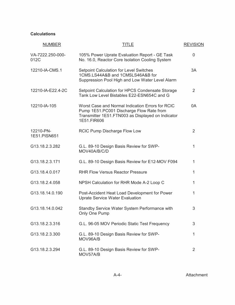
VA-7222.250-000-012C
105% Power Uprate Evaluation Report - GE TaskNo. 16.0, Reactor Core Isolation Cooling System
0
12210-IA-CMS.1 Setpoint Calculation for Level Switches1CMS.LS44A&B and 1CMSLS46A&B forSuppression Pool High and Low Water Level Alarm
3A
12210-IA-E22.4-2C Setpoint Calculation for HPCS Condensate StorageTank Low Level Bistables E22-ESN654C and G
2
12210-IA-105 Worst Case and Normal Indication Errors for RCICPump 1E51.PC001 Discharge Flow Rate fromTransmitter 1E51.FTN003 as Displayed on Indicator1E51.FIR606
0A
12210-PN-1E51.PISN651
RCIC Pump Discharge Flow Low 2
G13.18.2.3.282 G.L. 89-10 Design Basis Review for SWP-MOV40A/B/C/D
1
G13.18.2.3.171 G.L. 89-10 Design Basis Review for E12-MOV F094 1
G13.18.4.0.017 RHR Flow Versus Reactor Pressure 1
G13.18.2.4.058 NPSH Calculation for RHR Mode A-2 Loop C 1
G13.18.14.0.190 Post-Accident Heat Load Development for PowerUprate Service Water Evaluation
1
G13.18.14.0.042 Standby Service Water System Performance withOnly One Pump
3
G13.18.2.3.316 G.L. 96-05 MOV Periodic Static Test Frequency 3
G13.18.2.3.300 G.L. 89-10 Design Basis Review for SWP-MOV96A/B
1
G13.18.2.3.294 G.L. 89-10 Design Basis Review for SWP-MOV57A/B
2

Calculations
NUMBER TITLE REVISION
AttachmentA-5-
G13.18.2.3.293 G.L. 89-10 Design Basis Review for SWP-MOV55A/B
1
E-131 Station Service Short Circuit Analysis 1
E-132 Voltage Profile 3
E-143 Station Battery ENB-BAT01ADuty Cycle, CurrentProfile and Size Verification
9
E-176 Standby Load Center, MCC, and 120 Volt PanelShort Circuit Calculation
1
AX-108R_ADDC Evaluation of Replacement Isolation Valve SWP-MOV55A
6C
Condition Reports
1992-007401996-009311998-008731998-015011999-019142000-013592001-013982002-003762002-006432002-006712003-013132003-01353
2003-004962004-002742004-021182004-021362004-022382004-029152004-033812004-035852004-038162004-043562005-00870
2005-012382005-009982005-014192005-019912005-022762005-023082005-028452005-032122005-034222005-035252005-03887
2005-041762006-001702006-001752006-002342006-002832006-003222006-005062006-005552006-006932006-007922006-00881
2006-009162006-009542006-010262006-010842006-011962006-016802006-018622006-019292006-019592006-020042006-02458
Drawings
NUMBER TITLE REVISION
EB-7C Building Service - Ventilation Plan Elevation 126'0" &Sections - Standby Diesel Generator Building Sheet 3
10
EE-001B Main One Line Diagram Unit Relaying 17
EE-001C Main One Line Diagram Station Service Relaying 26

NUMBER TITLE REVISION
AttachmentA-6-
EE-001G 4160V One Line Diagram Bus NNS-SWG1A & 1B 10
EE-001J 4160V One Line Diagram Bus NNS-SWG3A, 3B & 1C 9
EE-001K 4160V One Line Diagram Standby Bus ENS-SWG1A 19
EE-001L 4160V One Line Diagram Standby Bus ENS.SWG1B 15
EE-001M 4160V One Line Diagram Standby Bus E22-S004 9
EE-001AA 480V One Line Diagram Standby Bus 1EJS.LDC 1A &2A
12
EE-001AB 480V One Line Diagram Standby Bus 1EJS.LDC 1B &2B
11
EE-001AC Start Up Electrical Distribution Chart 33
EE-1BR 480V One Line Diagram 1NHS-MCC101, MCC1LL1 &1LL2, Turbine Building
4
EE-001CE 480V One Line Diagram 1NHS-MCC102A & 102B,Auxiliary Building
12
EE-001SA 480V One Line Diagram 1E22.S002, Control Building 11
EE-001TA 480V One Line Diagram EHS-MCC2A & 2L, AuxiliaryBuilding
17
EE-001TB 480V One Line Diagram EHS-MCC2C & 2D, AuxiliaryBuilding
10
EE-001TC 480V One Line Diagram EHS-MCC2E, Auxiliary Building 10
EE-001TD 480V One Line Diagram EHS-MCC2G & 2H, AuxiliaryBuilding
11
EE-001TE 480V One Line Diagram EHS-MCC2J & 2K, AuxiliaryBuilding
19
EE-001TF 480V One Line Diagram EHS.MCC2B, Auxiliary Building 10
EE-001TG 480V One Line Diagram EHS.MCC2F, Auxiliary Building 14
EE-001VA 480V One Line Diagram EHS.MCC8A, StandbySwitchgear
10
EE-001WA 480V One Line Diagram EHS-MCC14A & 14B, StandbySWGR Room 1A
10
EE-001WB 480V One Line Diagram EHS-MCC16B, Standby CoolingTower No. 1
12

NUMBER TITLE REVISION
AttachmentA-7-
EE-001XA 480V One Line Diagram EHS-MCC15A, 15B & NHS-MCC15A, Diesel Generator Rooms 1A & 1B
8
EE-001YA 480V One Line Diagram EHS-MCC16A, Standby CoolingTower No. 1
11
EE-001YB 480V One Line Diagram EHS.MCC8B, StandbySwitchgear
9
EE-001ZD 125VDC One Line Diagram ENB-MCC1, AuxiliaryBuilding
6
EE-001ZG 125VDC One Line Diagram Standby Bus A, ENB-SWG01A, ENB-PNL02A, 03A
19
EE-001ZH 125VDC One Line Diagram Standby Bus B,ENB.SWG01B, ENB.PNL02B, 03B
20
EE-001ZJ 125VDC One Line Diagram Normal & Standby BackupCharger Sys
17
ESK-06CSH0E Elementary Diagram 480 V Control Circuit HPCS PumpInjection Shutoff & Minimum Flow to Suppression PoolValve
6
ESK-11ICS09 Elementary Diagram 125V DC Control Circuit RCICInjection Shutoff Valve
6
ESK-6RHS21 Elementary Diagram 480 V Control Circuit Residual HeatRemoval System
3
PID-27-06A Engineering P&I Diagram System 209 Reactor CoreIsolation Cooling
42
PID-27-07B System 204, Residual Heat Removal -LPCI 40
PID-09-10F Service Water Normal 29
PID-27-07A System 204, Residual Heat Removal - LPCI 35
PID-27-07B System 204, Residual Heat Removal - LPCI 40
PID-27-07C System 204, Residual Heat Removal - LPCI 25
PID-03-01B System 109, Main Steam 23
PID-03-01D System 202, SVV Compressor/Dryers 4
PID-27-20A System 208, MSIV Positive Leakage Control 9
PID-27-20C System 208, LSV-C3A Compressor Skid 2

NUMBER TITLE REVISION
AttachmentA-8-
PID-27-20D System 208, LSV-C3B Compressor Skid 4
PID-09-10E Engineering P&ID Diagram System 256, Service Water -Standby
20
PID-22-07A Engineering P&ID Diagram System 405, HVAC - DieselGenerators
19
PID-27-04A Engineering P&ID Diagram System 203, HPCS System 26
PID-27-07B Engineering P&ID Diagram System 204, Residual HeatRemoval - LPCI
40
12210-EM-32C-6 Machine Location Standby Service Water Cooling TowerNo. 1 - Sections
6
12210-EM-34B-7 Mach Locn Auxiliary Bldg Plans EL 114'0" & 141'0" 0
0221.415-000-101 125 VDC Distribution System 2600 kW. 4160V, 3i,60HZ, 0.8 pf Emergency Diesel Generator 22711AUSH. 1
H
0221.415-000-102 125 VDC Distribution System 2600 kW. 4160V, 3i,60HZ, 0.8 pf Emergency Diesel Generator 22711AU SH.No 2
G
0228-229-234-002 18" Class 150 Dual Plate Check Valve Assembly 0
0228-229-234-001 30" Class 150 Dual Plate Check Valve Assembly 0
0222.214-327-001 Air Compressor Assembly 0
VPF-B607-248-1 HPCS Pump Performance Curves 1
21A9236 HPCS - Engine - Generator 4
7308-5026 Pump Performance Curve Pump 18X23 VSN1 (ServiceWater)
0
01-400-293 Hayward Tyler Pump 01-400-293 F
Procedures
NUMBER TITLE REVISION
AOP-0004 Loss of Offsite Power 29
AOP-0050 Station Blackout 20
EOP-0001 RPV Control 20

NUMBER TITLE REVISION
AttachmentA-9-
EOP-0003 Secondary Containment and Radioactive ReleaseControl
13
EOP-0004 Contingencies 12
EOP-0005 Emergency Operating and Severe AccidentProcedures Enclosures
15B
SOP-0022 Instrument Air System 41A
SOP-0031 Residual Heat Removal 47
SOP-0042 Standby Service Water System 25
SOP-0046 4.16 KV System 29
SOP-0054 Station Blackout Diesel Generator 4A
SOP-0059 Containment HVAC System 27
OSP-0053 Emergency and Transient Response SupportProcedure
4
JPM-204-01 Place RHR A in SPC Mode 5
RJPM-OPS-800-07 Inject Fire System into RPV 8
RJPM-OPS-80005 Defeating MSR Steam Supply Valve Interlocks 6
RJPM-OPS-800-21 Emergency Containment Venting 2
RSMS-OPS-417 Loss of Offsite Power 6
RSMS-OPS-420 Station Blackout and Restoration 3
RSMS-OPS-442 Loss of Circ Water Pump/Failure of Feed FlowTransmitter/IAS Leak
3
RSMS-OPS-621 MSIV Closure ATWS With SRV Relief FunctionFailure
2
AOP-0016 Loss of Standby Service Water 13
MCP-4195 Maintenance Calibration Procedure - Calibration ofthe RCIC Turbine Speed Controls
4
EN-DC-195 Margin Management 0
GMP-1282 Limitorque SMB-000 and SMB/SM-00 Overhaul 13
GMP-0108 Signature Testing of Gate, Globe, and TorqueSeated Butterfly Valves with Limitorque Actuators
5

NUMBER TITLE REVISION
AttachmentA-10-
A&M 303-10975 30"Tricentric Butterfly Valve 1
STP-000-6606 Section IX Safety and Relief Valve Testing 16
STP-051-4247 ECCS Press Low/SRV Actuation 14A
STP-051-4248 ECCS Reactor Vessel Pressure Low/SRV ActuationInstrumentation Channel Calibration Test
13A
STP-051-4298 ADS “A” Drywell Pressure Bypass Timer FunctionalTest and Channel Calibration
07 & 6A
STP-051-4299 ADS “B” Drywell Pressure Bypass Timer FunctionalTest and Channel Calibration
08
STP-202-0601 Relief Valve Low Low Set ADS A Manual InitiationSystem Functional Test
9A
STP-202-0603 Relief Valve Low Low Set ADS B Manual InitiationSystem Functional Test
9A
STP-202-6606 ADS SRV Accumulator Check Valve Leak RateOperability Test
3A
STP-202-7700 Safety Relief Valve Actuator Stroke Test 2
STP-204-6302 Div II LPCI (RHR) Quarterly Pump & ValveOperability Test
16
SOP-0011 Main Steam System (SYS #109) 21
STP-107-3806 RCIC E51-MOVF013, Post-Maintenance Test 9
STP-203-6305 HPCS Quarterly Pump and Valve Operability Test 15
STP-209-0602 RCIC System Flow Test (Low Pressure) 12A
STP-209-6310 RCIC Quarterly Pump and Valve Operability Test 26
STP-256-6303 Standby Service Water A Loop Valve and PumpOperability Test
17
STP-256-6304 Standby Service Water B Loop Valve and PumpOperability Test
16A
STP-256-6801 Division 1 Standby Service Water Cold ShutdownValve Operability Test
2A
STP-256-6603 Division 1 Service Water 2 year Position Indication 3
STP-256-6301 Division 1 Standby Service Water Quarterly ValveOperability Test
11
NUMBER TITLE REVISION
AttachmentA-11-
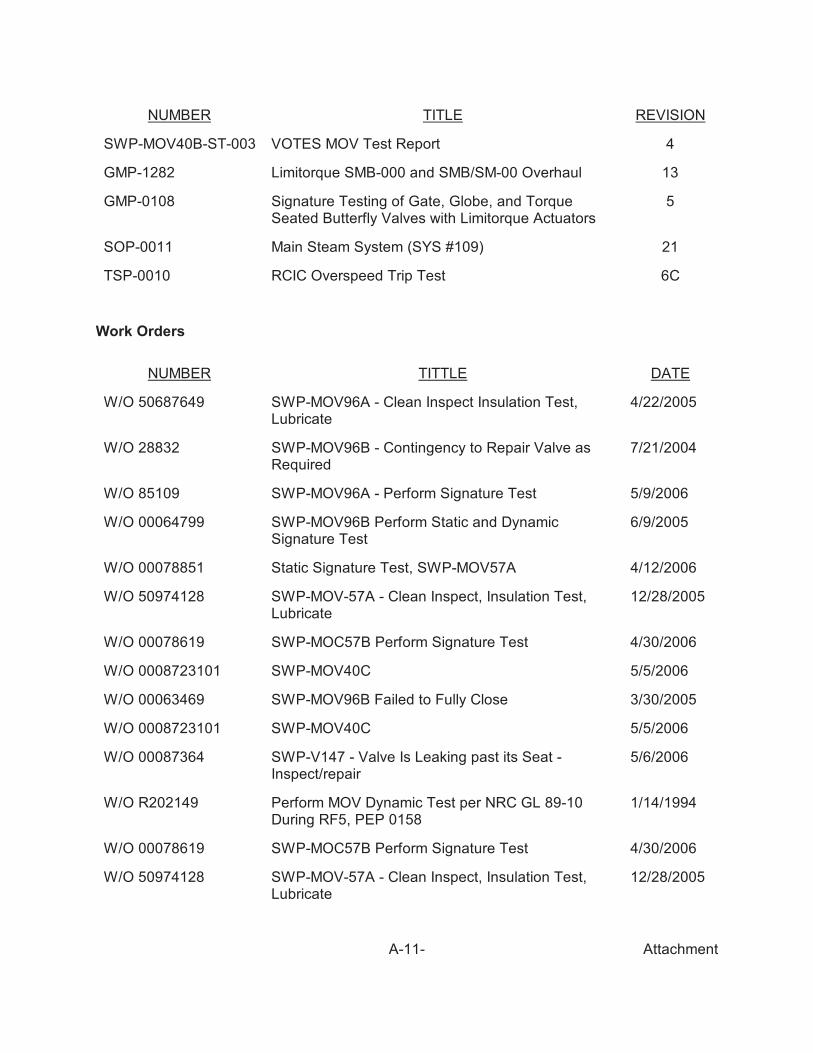
SWP-MOV40B-ST-003 VOTES MOV Test Report 4
GMP-1282 Limitorque SMB-000 and SMB/SM-00 Overhaul 13
GMP-0108 Signature Testing of Gate, Globe, and TorqueSeated Butterfly Valves with Limitorque Actuators
5
SOP-0011 Main Steam System (SYS #109) 21
TSP-0010 RCIC Overspeed Trip Test 6C
Work Orders
NUMBER TITTLE DATE
W/O 50687649 SWP-MOV96A - Clean Inspect Insulation Test,Lubricate
4/22/2005
W/O 28832 SWP-MOV96B - Contingency to Repair Valve asRequired
7/21/2004
W/O 85109 SWP-MOV96A - Perform Signature Test 5/9/2006
W/O 00064799 SWP-MOV96B Perform Static and DynamicSignature Test
6/9/2005
W/O 00078851 Static Signature Test, SWP-MOV57A 4/12/2006
W/O 50974128 SWP-MOV-57A - Clean Inspect, Insulation Test,Lubricate
12/28/2005
W/O 00078619 SWP-MOC57B Perform Signature Test 4/30/2006
W/O 0008723101 SWP-MOV40C 5/5/2006
W/O 00063469 SWP-MOV96B Failed to Fully Close 3/30/2005
W/O 0008723101 SWP-MOV40C 5/5/2006
W/O 00087364 SWP-V147 - Valve Is Leaking past its Seat -Inspect/repair
5/6/2006
W/O R202149 Perform MOV Dynamic Test per NRC GL 89-10During RF5, PEP 0158
1/14/1994
W/O 00078619 SWP-MOC57B Perform Signature Test 4/30/2006
W/O 50974128 SWP-MOV-57A - Clean Inspect, Insulation Test,Lubricate
12/28/2005

NUMBER TITTLE DATE
AttachmentA-12-
W/O 00029620 SWP-MOV-57B - Clean Inspect, Insulation Test,Lubricate
1/23/2004
W/O 00078851 Static Signature Test, SWP-MOV57A 4/12/2006
W/O 50687140 Perform Seat Leakage Test of WSP-MOV96A 9/17/2004
W/O 50687649 SWP-MOV96A - Clean Inspect Insulation Test,Lubricate
4/22/2005
W/O 85109 SWP-MOV96A - Perform Signature Test 5/9/2006
W/O 28832 SWP-MOV96B - Contingency to Repair Valve asRequired
7/21/2004
W/O 50687139 SWP-MOV96B - Perform Seat Leakage Test ofSWP-MOV96B
9/17/2004
W/O 00063469 SWP-MOV96B Failed to Fully Close 3/30/2005
W/O 00064799 SWP-MOV96B Perform Static and DynamicSignature Test
6/9/2005
W/O 0006610001 TSP-0010 RCIC Overspeed 5/12/2006
W/O 5103029901 STP-203-6305 HPCS Quarterly Pump and ValveOperability Test
3/28/2006
Engineering Requests
NUMBER TITTLE REVISION/DATE
ER-0745 Modify Safety Related Limitorque Actuator toincrease the torque output capability as a result ofLimitorque Technical Update 98-01
0
ER-97-0232 Replacement of the Service Water Valves 8/27/1997
ER-RB-2000-0345 SWP MOV Upgrade 0
ER-RB-1998-0580-000 Revise Documentation to Reflect EffectiveReduction in HPCS/RCIC CST Reserve Volume Dueto Flow Induced Instrument Error
0
ER-RB-2000-0330-000 Install Relief Valves on the Return Lines of theContainment Unit Coolers, HVR-UC1A andHVR-UC1B
0

AttachmentA-13-
ER-RB-2001-0296-000 “Replace RCIC Lube Oil Cooler OrificePlate E51-ROD012
0
ER-RB-2004-0080-000 Replace 230KV Transformer Disconnect Switchesfor Preferred Station Service Transformers and MainTransformer
0
ER-RB-2004-0256-000 Replace Air Operated Valve Actuator Diaphragmswith New EPDM/Nomex Type
0
ER-RB-2004-0307-000 Replace O-Ring on Fisher AOV from Nitrite to Viton 0
ER-RB-2004-0487-000 Replace MOV Actuator with Angled Actuator 0
ER 98-0206 Perform a Review of Design Basis Limiting Valuesfor Pump Flow and Differential PressureRequirements
11/24/1998
Miscellaneous Documents
NUMBER TITTLE DATE/REVISION
NCIG-05 EPRI Guideline for Piping System Reconciliation 1
WLAS31274-07 Minimum Required Operating Torque and WeakLink Analysis
A
LTU 98-01 Actuator Output Torque Calculation 5/15/1998
R-STM-0118 System Training Manual - Service Water Systems 11
WLAS31274-04 Minimum Required Operating Torque and WeakLink Analysis
A
EQAR-025 River Bend Nuclear Station EnvironmentalQualification Assessment Report (EQAR) forLimitorque Motorized Valve Actuators with Class BInsulated AC Motors
2
E/IC-95-001 River Bend Station Engineering Report forMechanical Equipment Qualification ProgramDeletion
0
8020 VMT1F-7558 (218RHR)
Byron Jackson Pump DivisionTechnical Manual for Vertical RHR PumpType: 28 DX 18.5 CKXL, Three-Stage VMT
9
SDC-108,109,202 Main Steam System Design Criteria 03

NUMBER TITTLE DATE/REVISION
AttachmentA-14-
E12-MOVF094-ST-003 VOTES MOV Test Report 0
STP-204-6304R14PR-15
Procedure Action Request 0
ISTCN No.08-003 Change Summary for the IST Program 10 YearUpdate
0
OE-IN 93-68 Failure of Pump Shaft Coupling Caused by TemperEmbrittlement During Manufacture
0
OE-IN944500.SA1 Potential Common Mode Failure Mechanism forLarge Vertical Pumps
0
Fire Area AB-15 Summary Table 0
42069-R-001 Seismic Verification of Ingersoll Rand Model 7C3 AirCompressor for the River Bend Station
0
ER-RB-2001-0595-000 Revise the Post-fire Safe Shutdown Analysis toIncorporate the Conclusions of Calc G13.18.2.6.034
0
NEDO-10905 General Electric Licensing Topical Report HighPressure Core Spray System Power Supply Unit
May 1973