VIBRATION SUPPRESSION PROBLEMS IN NON-RIGID …
10
VIBRATION SUPPRESSION PROBLEMS IN NON-RIGID STRUCTURES TAKING A VIBRATING SIFTER AS AN EXAMPLE Janusz Zachwieja University of Technology and Life Sciences, Department of Applied Mechanics, Mechanical Engineering Faculty str. S.Kaliskiego 5, 85-796 Bydgoszcz email: [email protected] Abstract This paper presents the problems encountered in the suppression of vibration in machines with a low degree of rigidity, especially when the vibration is to be suppressed in only part of a facility, as the oscillatory motion of the remaining equipment in the team is its normal working movement. An example of such a device is a vibrating sifter, this being a machine with a percussive (shock) way of operating. The nature of vibrations in this type of equipment depends on the foundation’s rigidity as well as the rigidity of the screen itself. Both may undergo change during operation of the machine, due to cracking of structural elements as a result of the impact of the force causing the movement of the screened material. Keywords: own natural vibration, vibration suppression 1. Introduction The motion of operating machine units such as mills, sifters and vibrating conveyors [1,2] is vibratory. Diagnosing the dynamic state of a machine with a percussive (shock) operation is a complex issue due to the presence in the system of excitations of considerable amplitudes and frequencies acting not only on the whole operating unit but also on other components of the machine and the environment, which is an undesirable effect. The design of such machines should provide good vibration insulation for the working components. In many cases, however, this is not efficient enough to meet the demands of the machines’ work environment, such as the proximity of measuring devices or the presence of people. Often the cause of the incorrect operation of these devices lies in modifications introduced in order to improve performance, or else their foundations being incorrectly constructed. The Building Law requires calculations of the load capacity of foundations for large-scale facilities such as mills or foundry hammers. The conditions governing foundations for vibrating sifters are however less stringent. Usually these are located directly on the factory floor, which is often not adapted to this role. The vibration velocity of the screen – the sifter’s operating component – is in the order of 100 mm·s -1 and its displacement amounts to several millimetres. Thus the forces resulting from the mass and the acceleration of the team when in motion are significant, making it necessary to apply an effective method of insulating the machine’s vibration [3]. Both the screen and the structure on which it is installed are not rigid. The effectiveness of screening depends on the sensitivity of the vibration dampers. Both these factors compound to
Transcript of VIBRATION SUPPRESSION PROBLEMS IN NON-RIGID …

VIBRATION SUPPRESSION PROBLEMS IN NON-RIGID STRUCTURES TAKING A VIBRATING SIFTER AS AN EXAMPLE
Janusz Zachwieja
University of Technology and Life Sciences, Department of Applied Mechanics, Mechanical Engineering Faculty
str. S.Kaliskiego 5, 85-796 Bydgoszcz email: [email protected]
Abstract
This paper presents the problems encountered in the suppression of vibration in machines with a low degree of rigidity, especially when the vibration is to be suppressed in only part of a facility, as the oscillatory motion of the remaining equipment in the team is its normal working movement. An example of such a device is a vibrating sifter, this being a machine with a percussive (shock) way of operating. The nature of vibrations in this type of equipment depends on the foundation’s rigidity as well as the rigidity of the screen itself. Both may undergo change during operation of the machine, due to cracking of structural elements as a result of the impact of the force causing the movement of the screened material.
Keywords: own natural vibration, vibration suppression
1. Introduction
The motion of operating machine units such as mills, sifters and vibrating conveyors [1,2] is vibratory. Diagnosing the dynamic state of a machine with a percussive (shock) operation is a complex issue due to the presence in the system of excitations of considerable amplitudes and frequencies acting not only on the whole operating unit but also on other components of the machine and the environment, which is an undesirable effect. The design of such machines should provide good vibration insulation for the working components. In many cases, however, this is not efficient enough to meet the demands of the machines’ work environment, such as the proximity of measuring devices or the presence of people. Often the cause of the incorrect operation of these devices lies in modifications introduced in order to improve performance, or else their foundations being incorrectly constructed. The Building Law requires calculations of the load capacity of foundations for large-scale facilities such as mills or foundry hammers. The conditions governing foundations for vibrating sifters are however less stringent. Usually these are located directly on the factory floor, which is often not adapted to this role. The vibration velocity of the screen – the sifter’s operating component – is in the order of 100 mm·s-1 and its displacement amounts to several millimetres. Thus the forces resulting from the mass and the acceleration of the team when in motion are significant, making it necessary to apply an effective method of insulating the machine’s vibration [3].
Both the screen and the structure on which it is installed are not rigid. The effectiveness of screening depends on the sensitivity of the vibration dampers. Both these factors compound to
cause the frequency range in which own, natural vibration occurs to be broad [4,5]. Variable loads on the device’s structure, causing a variable state of stress, significantly reduce the machine’s endurance. The resulting cracks reduce the structure’s rigidity uncontrollably. It is very likely that in these conditions, vibrations will adopt a sudden resonant nature, which involves the risk of damage to or even degradation of the structure.
2. The dynamic state of the device before upgrade of the sifter support method
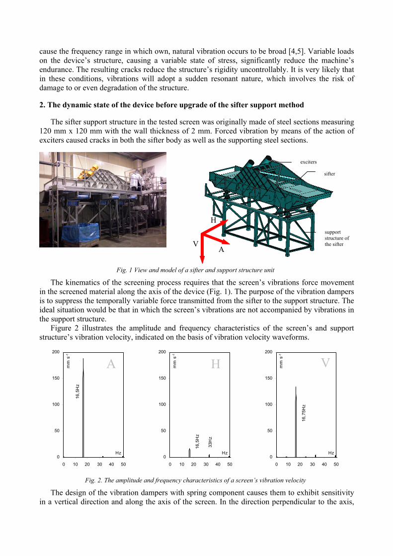
The sifter support structure in the tested screen was originally made of steel sections measuring 120 mm x 120 mm with the wall thickness of 2 mm. Forced vibration by means of the action of exciters caused cracks in both the sifter body as well as the supporting steel sections.
Fig. 1 View and model of a sifter and support structure unit
The kinematics of the screening process requires that the screen’s vibrations force movement in the screened material along the axis of the device (Fig. 1). The purpose of the vibration dampers is to suppress the temporally variable force transmitted from the sifter to the support structure. The ideal situation would be that in which the screen’s vibrations are not accompanied by vibrations in the support structure.
Figure 2 illustrates the amplitude and frequency characteristics of the screen’s and support structure’s vibration velocity, indicated on the basis of vibration velocity waveforms.
16,
5Hz
0
50
100
150
200
0 10 20 30 40 50
Hz
mm
s-1
33H
z
16,
5Hz
0
50
100
150
200
0 10 20 30 40 50
Hz
mm
s-1
16,
75H
z
0
50
100
150
200
0 10 20 30 40 50
Hz
mm
s-1
Fig. 2. The amplitude and frequency characteristics of a screen’s vibration velocity
The design of the vibration dampers with spring component causes them to exhibit sensitivity in a vertical direction and along the axis of the screen. In the direction perpendicular to the axis,
support structure of the sifter
sifter
exciters
A VH
H
A V
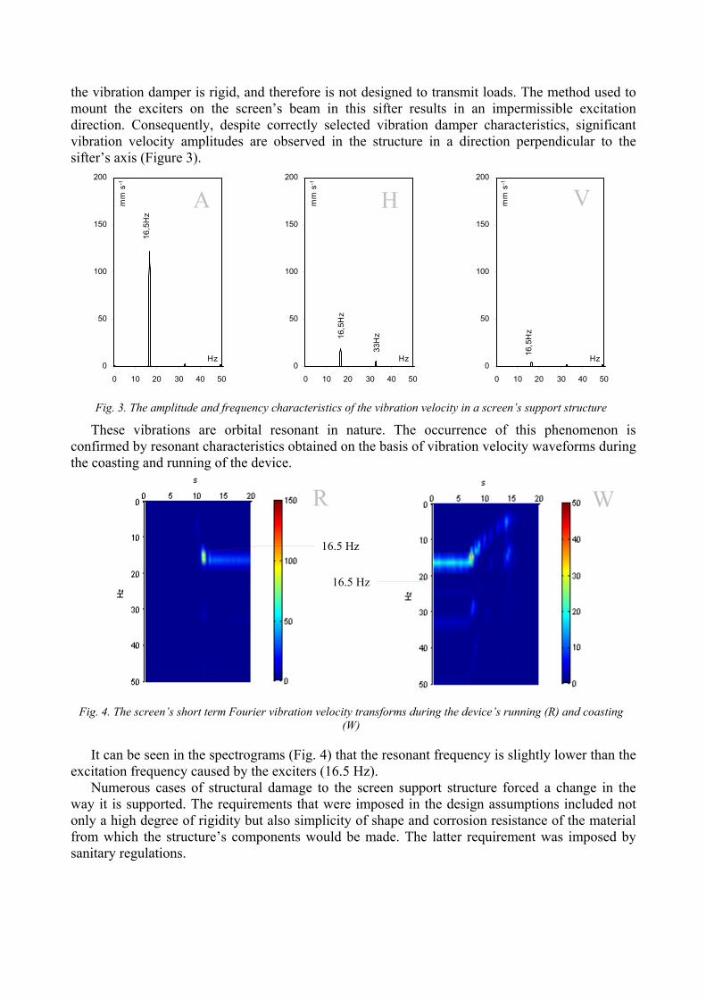
the vibration damper is rigid, and therefore is not designed to transmit loads. The method used to mount the exciters on the screen’s beam in this sifter results in an impermissible excitation direction. Consequently, despite correctly selected vibration damper characteristics, significant vibration velocity amplitudes are observed in the structure in a direction perpendicular to the sifter’s axis (Figure 3).
16,5
Hz
0
50
100
150
200
0 10 20 30 40 50
Hz
mm
s-1
33
Hz16,
5Hz
0
50
100
150
200
0 10 20 30 40 50
Hz
mm
s-1
16,5
Hz
0
50
100
150
200
0 10 20 30 40 50
Hz
mm
s-1
Fig. 3. The amplitude and frequency characteristics of the vibration velocity in a screen’s support structure
These vibrations are orbital resonant in nature. The occurrence of this phenomenon is confirmed by resonant characteristics obtained on the basis of vibration velocity waveforms during the coasting and running of the device.
Fig. 4. The screen’s short term Fourier vibration velocity transforms during the device’s running (R) and coasting
(W)
It can be seen in the spectrograms (Fig. 4) that the resonant frequency is slightly lower than the excitation frequency caused by the exciters (16.5 Hz).
Numerous cases of structural damage to the screen support structure forced a change in the way it is supported. The requirements that were imposed in the design assumptions included not only a high degree of rigidity but also simplicity of shape and corrosion resistance of the material from which the structure’s components would be made. The latter requirement was imposed by sanitary regulations.
A VH
R W
16.5 Hz
16.5 Hz

3. The dynamic state of the device following upgrade of the screen support method
Finally, from the many options under consideration [6], the solution shown in Figure 5 was selected.
Fig. 5. View and model of the screen support structure after upgrading
Based on the weight of the screen and impact of the exciters, it was calculated at the design stage that the stresses in the cross-sections of the upgraded structure should not exceed 40 MPa. The specified value of the stresses is so low that for the material from which the components are made (namely 1.4301 grade steel), the figure does not exceed the limit even for variable loads. The maximum deformation of the screen’s support columns should be less than 1 mm. The support structure’s high degree of rigidity following its upgrade is confirmed by the expected frequency of its own natural vibrations - 54 Hz (Fig. 6).
Fig. 6. The lowest expected frequency of the screen support structure’s own, natural vibrations following its upgrade and the stresses and strains in cross-sections
Tests of the screen’s dynamics were performed following its installation on the upgraded support structure. Based on the amplitude and frequency characteristics of vibration parameters, it can be claimed that the intended effect, namely a significant reduction in the level of vibration in the support structure, while maintaining the screen’s required vibration velocity parameters, was successfully achieved (Figs. 7-8).
54Hz 40MPa 0.79mm
16,5
Hz
0
50
100
150
200
0 10 20 30 40 50
Hz
mm
s-1
16,
75H
z
0
50
100
150
200
0 10 20 30 40 50
Hz
mm
s-1
16,
75H
z
0
50
100
150
200
0 10 20 30 40 50
Hz
mm
s-1
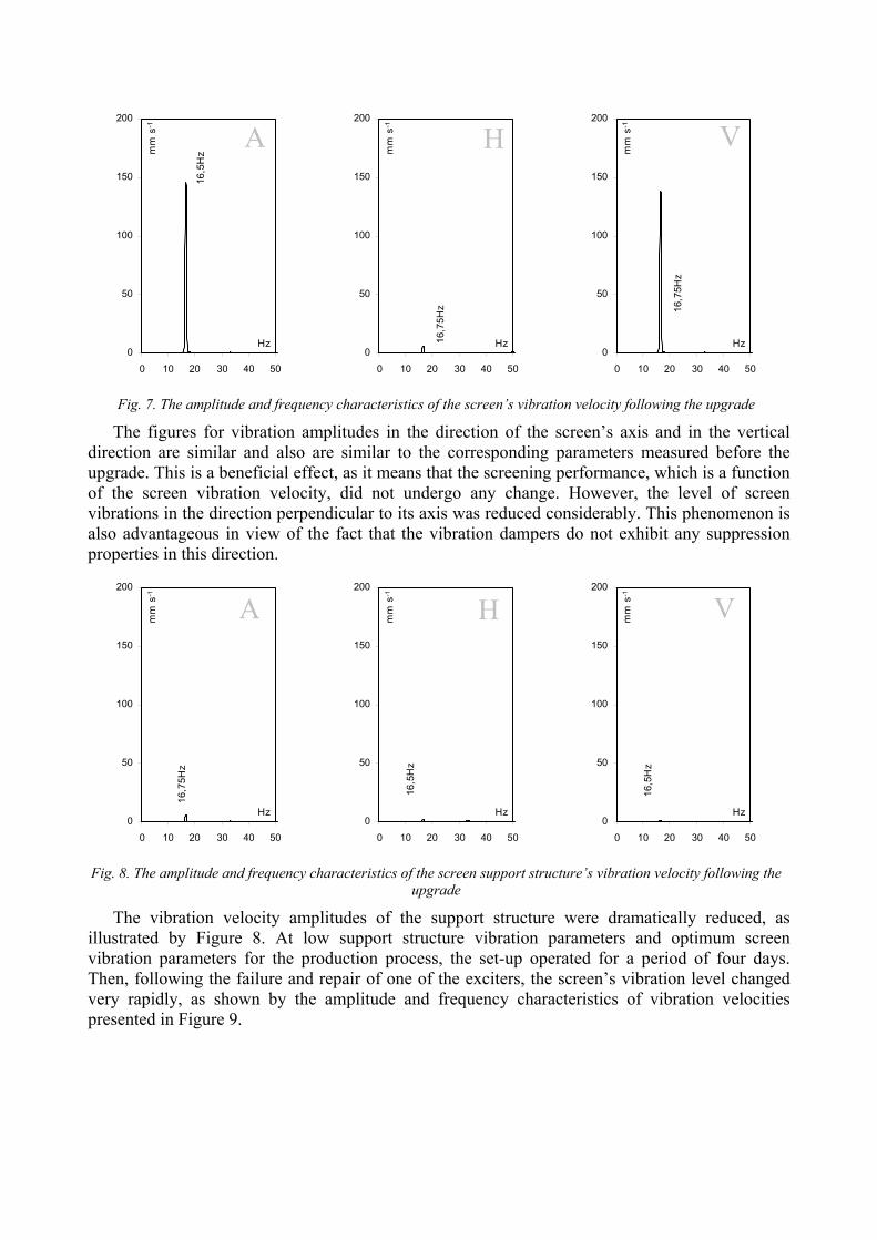
Fig. 7. The amplitude and frequency characteristics of the screen’s vibration velocity following the upgrade
The figures for vibration amplitudes in the direction of the screen’s axis and in the vertical direction are similar and also are similar to the corresponding parameters measured before the upgrade. This is a beneficial effect, as it means that the screening performance, which is a function of the screen vibration velocity, did not undergo any change. However, the level of screen vibrations in the direction perpendicular to its axis was reduced considerably. This phenomenon is also advantageous in view of the fact that the vibration dampers do not exhibit any suppression properties in this direction.
16,
75H
z
0
50
100
150
200
0 10 20 30 40 50
Hz
mm
s-1
16,5
Hz
0
50
100
150
200
0 10 20 30 40 50
Hz
mm
s-1
16,
5Hz
0
50
100
150
200
0 10 20 30 40 50
Hz
mm
s-1
Fig. 8. The amplitude and frequency characteristics of the screen support structure’s vibration velocity following the upgrade
The vibration velocity amplitudes of the support structure were dramatically reduced, as illustrated by Figure 8. At low support structure vibration parameters and optimum screen vibration parameters for the production process, the set-up operated for a period of four days. Then, following the failure and repair of one of the exciters, the screen’s vibration level changed very rapidly, as shown by the amplitude and frequency characteristics of vibration velocities presented in Figure 9.
A VH
A VH

15,
25H
z
16,
5Hz
0
50
100
150
200
0 5 10 15 20 25
Hz
mm
s-1
15,2
5Hz
17,
5H
z
0
50
100
150
200
250
300
0 5 10 15 20 25
Hz
mm
s-1
17,
5H
z16,
25H
z
15,2
5Hz
0
50
100
150
200
250
300
350
400
450
0 5 10 15 20 25
Hz
mm
s-1
Fig. 9. The amplitude and frequency characteristics of the screen’s vibration velocity following the failure of the
exciter
While in the direction of the screen’s axis the vibration amplitude for the excitation frequency was slightly reduced, it grew rapidly in the vertical direction and in the direction perpendicular to the screen’s axis in case of the 15.25 Hz and 17.5 Hz frequencies. The occurrence of very large vibration amplitudes at the frequency of 15.25 Hz would indicate that this is a resonant frequency. Comparison of the charts (Figures 7 and 9) suggests that before the failure of the exciter, the rigidity of the unit must have been greater, and then was reduced, due to which the frequency of resonant vibrations also decreased. Reduction in the rigidity may be linked to the damage to one of the exciters, as for a few hours the screen was subjected to a force perpendicular to its axis. Under normal operating conditions, i.e. when two exciters are in operation, this force does not occur. However, it is puzzling that the vibration spectra presented in Figure 7 show no visible amplitudes for own, natural frequencies in the area of excitation frequencies, which may mean that the suppression in the system is considerable. It must have been reduced, since the amplitudes of resonance vibrations with a frequency of 15.25 Hz show large values at an excitation frequency greater by only 1 Hz. This effect must be considered inexplicable.
Fig. 10. The screen’s short term Fourier vibration velocity transforms as indicated during the device’s running (R) and coasting (W) following the failure of the exciter
The screen’s vibration velocity spectrograms prove that the frequency of the screen’s own, natural vibrations changed following the upgrade of the support structure. Figure 4 shows that prior to the upgrade, the resonance frequency was smaller than the rotational frequency of the exciters and that presently, the excitation frequency falls within the range of orbital resonance
A VH
R W16.5 Hz
16.5 Hz
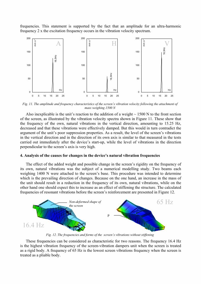
frequencies. This statement is supported by the fact that an amplitude for an ultra-harmonic frequency 2 x the excitation frequency occurs in the vibration velocity spectrum.
16,
5Hz
0
50
100
150
200
0 5 10 15 20 25
Hz
mm
s-1
16,
5Hz
0
50
100
150
200
0 5 10 15 20 25
Hzm
m s
-1
16,
5Hz
0
50
100
150
200
0 5 10 15 20 25
Hz
mm
s-1
Fig. 11. The amplitude and frequency characteristics of the screen’s vibration velocity following the attachment of mass weighing 1500 N
Also inexplicable is the unit’s reaction to the addition of a weight ~ 1500 N to the front section of the screen, as illustrated by the vibration velocity spectra shown in Figure 11. These show that the frequency of the own, natural vibrations in the vertical direction, amounting to 15.25 Hz, decreased and that these vibrations were effectively damped. But this would in turn contradict the argument of the unit’s poor suppression properties. As a result, the level of the screen’s vibrations in the vertical direction and in the direction of its own axis is similar to that measured in the tests carried out immediately after the device’s start-up, while the level of vibrations in the direction perpendicular to the screen’s axis is very high.
4. Analysis of the causes for changes in the device’s natural vibration frequencies
The effect of the added weight and possible change in the screen’s rigidity on the frequency of its own, natural vibrations was the subject of a numerical modelling study. Two beams each weighing 1400 N were attached to the screen’s base. This procedure was intended to determine which is the prevailing direction of changes. Because on the one hand, an increase in the mass of the unit should result in a reduction in the frequency of its own, natural vibrations, while on the other hand one should expect this to increase as an effect of stiffening the structure. The calculated frequencies of resonant vibrations before the screen’s reinforcement are presented in Figure 12.
Fig. 12. The frequencies and forms of the screen’s vibrations without stiffening
These frequencies can be considered as characteristic for two reasons. The frequency 16.4 Hz is the highest vibration frequency of the screen-vibration dampers unit when the screen is treated as a rigid body. A frequency of 65 Hz is the lowest screen vibrations frequency when the screen is treated as a pliable body.
A VH
16.4 Hz
65 Hz
P
Non-deformed shape of the screen
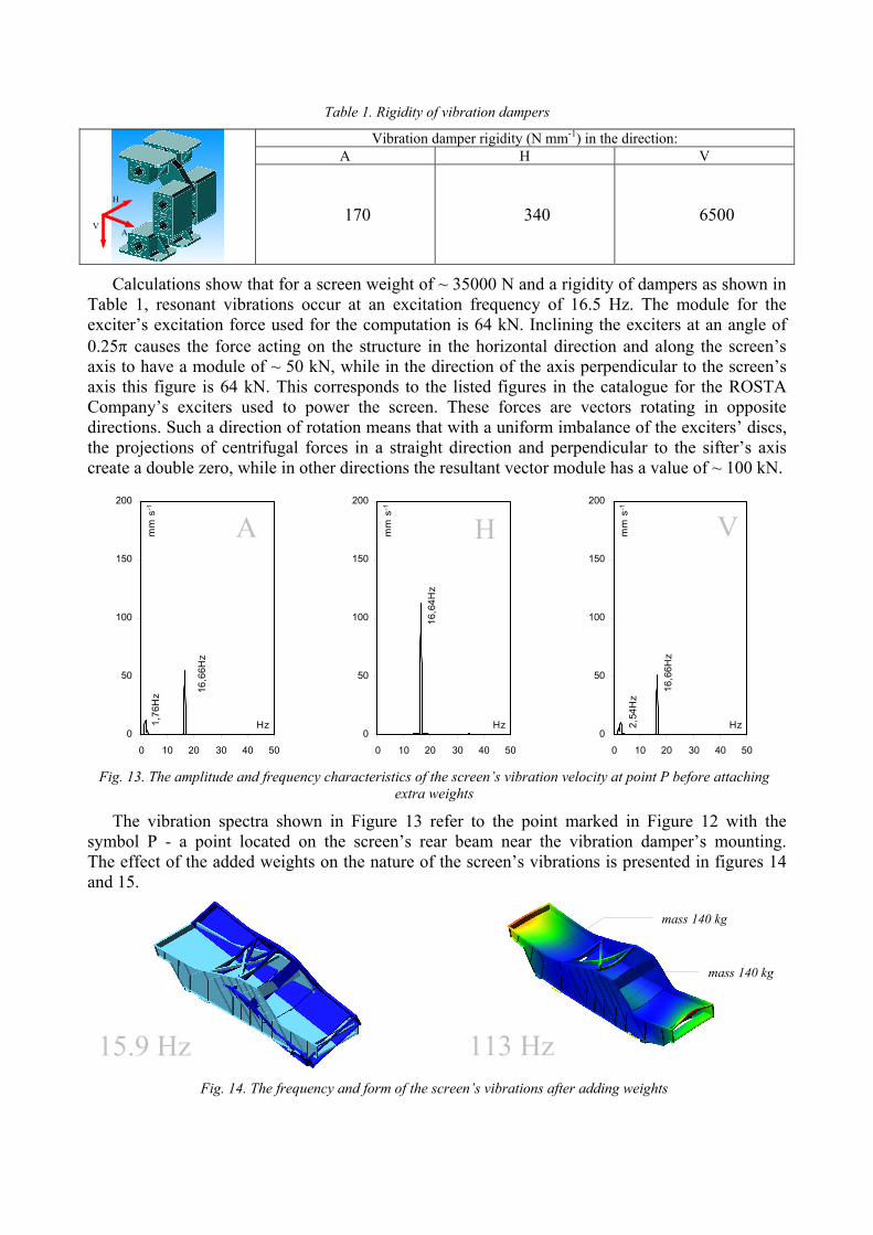
Table 1. Rigidity of vibration dampers
Vibration damper rigidity (N mm-1) in the direction: A H V
170 340 6500
Calculations show that for a screen weight of ~ 35000 N and a rigidity of dampers as shown in Table 1, resonant vibrations occur at an excitation frequency of 16.5 Hz. The module for the exciter’s excitation force used for the computation is 64 kN. Inclining the exciters at an angle of 0.25 causes the force acting on the structure in the horizontal direction and along the screen’s axis to have a module of ~ 50 kN, while in the direction of the axis perpendicular to the screen’s axis this figure is 64 kN. This corresponds to the listed figures in the catalogue for the ROSTA Company’s exciters used to power the screen. These forces are vectors rotating in opposite directions. Such a direction of rotation means that with a uniform imbalance of the exciters’ discs, the projections of centrifugal forces in a straight direction and perpendicular to the sifter’s axis create a double zero, while in other directions the resultant vector module has a value of ~ 100 kN.
1,76
Hz
16,6
6Hz
0
50
100
150
200
0 10 20 30 40 50
Hz
mm
s-1
16,
64H
z
0
50
100
150
200
0 10 20 30 40 50
Hz
mm
s-1
2,54
Hz
16,
66H
z
0
50
100
150
200
0 10 20 30 40 50
Hz
mm
s-1
Fig. 13. The amplitude and frequency characteristics of the screen’s vibration velocity at point P before attaching extra weights
The vibration spectra shown in Figure 13 refer to the point marked in Figure 12 with the symbol P - a point located on the screen’s rear beam near the vibration damper’s mounting. The effect of the added weights on the nature of the screen’s vibrations is presented in figures 14 and 15.
Fig. 14. The frequency and form of the screen’s vibrations after adding weights
mass 140 kg
mass 140 kg
15.9 Hz 113 Hz
A VH
H
A V

As one might expect, stiffening did not affect the form of the screen’s own, natural vibrations when it was treated as a rigid body. Only the resonant frequency changed slightly. It is worth noting that the attached weight, amounting of 8% of the screen’s weight, reduced its resonant frequency by only about 0.5 Hz.
1,7
6Hz
16,
66H
z
0
50
100
150
200
0 10 20 30 40 50
Hz
mm
s-1
16,6
4H
z0
50
100
150
200
0 10 20 30 40 50
Hz
mm
s-1
2,54
Hz
16,
66H
z
0
50
100
150
200
0 10 20 30 40 50
Hz
mm
s-1
Fig. 15. The amplitude and frequency characteristics of the screen’s vibration velocity at point P following attachment of the weights
However, the nature of vibrations changed significantly when the screen was treated as a sensitive body. There is no longer a tendency visible in Figure 12 to torsional vibrations of the screen body, while the frequency of its own, natural vibrations increased almost twofold.
12,5
Hz
0
50
100
150
200
0 10 20 30 40 50
Hz
mm
s-1
12,
5Hz
0
50
100
150
200
0 10 20 30 40 50
Hz
mm
s-1
12,5
Hz
0
50
100
150
200
0 10 20 30 40 50
Hz
mm
s-1
Fig. 16. The amplitude and frequency characteristics of the screen’s vibration velocity at point P following a change in the excitation frequency of the exciters
A much better effect than resonance vibration suppression by means of weights is achieved by changing the excitation frequency. This can be seen on the vibration velocity spectra presented in Figure 16. Lowering the excitation frequency by 4 Hz causes the unit to move away from the resonance area. The effectiveness of the screening process will be maintained, because the amplitudes of the vibrations velocity, apart from the direction perpendicular to the screen’s axis, exceed 100 mm·s-1. If, however, it turned out that these figures are too low, one may increase the amount of imbalance in the discs of the exciters.
A VH
A VH

5. Conclusions
Both the results of testing the nature of the sifter’s vibrations as well as the results obtained on the basis of numerical modelling show that suppression for this type of machine is not a simple issue. For example, changing the rigidity of the screen radically affects the sifter’s vibration frequency only in relation to the vibrations of a continuous unit. Lower frequencies of own, natural vibrations resulting from treatment of the screen as a rigid body are not substantially changed. The attachment of a weight of 2800 N, representing less than 10% of the screen’s weight, reduced the resonance frequency by a mere 0.5 Hz. Although suppression by means of added weights made it possible to remove the unit from the area of resonant vibration, this exhibited a high degree of unpredictability in the obtained results in respect of changes in vibration amplitudes in directions in which resonance did not occur. This effect was observed during tests of the sifter. The dynamic state represented by the amplitude and frequency characteristics in Figure 12 is the best result of transferring weights to various points on the screen. The results of numerical calculations show that a satisfactory suppression effect is achieved by changing the excitation frequency. Vibration amplitudes in directions A and V remained high, which ensures the proper performance of the screening process, while at the same time the vibration velocity amplitude of the sifter in a direction perpendicular to its axis was reduced. This is advantageous, since it ensures lower stress values in the screen’s cross-sections. This is because the structure of the vibration dampers used does not provide the proper vibration suppression conditions in this direction.
References
[1] Chmielewski T., Zembaty Z., Podstawy dynamiki budowli, Arkady, Warszawa, 1998. [2] Borkowski W., Konopka S., Prochowski L., Dynamika maszyn roboczych, WNT, Warszawa,
1996. [3] Zachwieja J., Gołębiowska I., Efektywność wybranych metod ochrony przeciwdrganiowej
konstrukcji wsporczej separatorów, Budownictwo Ogólne, Wydawnictwa UTP, pp. 119-126, 2009.
[4] Zachwieja J., Gołębiowska I,. Damping building vibrations excited by survace wave propagating in the ground. Journal of Polish CIMAC, 7(3), 2012, s. 373-381.
[5] Praca zbiorowa, Wspomaganie konstruowania układów redukcji drgań i hałasu, WNT, Warszawa, 2001.
[6] Zachwieja J., Application of numerical analysis in dynamic state diagnosis of the machine with a shock character of operation, Diagnostyka, 63, pp. 63-68, 2012.