
Vibration Project
15
Stick-slip oscillations in drill strings Name: Vivian Lim Zher Yee ID: 13872 Abstract: Drill string vibration is one of the major causes for a deteriorated drilling performance. Field experience revealed that it is crucial to understand the complex vibrational mechanisms experienced by a drilling system in order to better control its functional operation and improve its performance. Sick–slip oscillations due to contact between the drilling bit and formation is known to excite severe torsional and axial vibrations in the drill string. Stick-slip is a major cause of torsional vibrations and many researchers tried to minimize its effect on the behavior of the drill string using active damping technique. These techniques reduce the torque fluctuations and the torsional drill string vibrations affecting in this manner the stick-slip conditions. The underlying concept is to reduce the amplitude of the down holes rotational vibrations using torque feedback. The feedback is used by the rotational drives which slow down the rotary rate when the torque increases and speeds it up when the torque decreases. A dynamic model of the drill string including the drill pipes and drill collars is formulated. The equation of motion of the rotating drill string is derived using Lagrangian approach in conjunction with the finite element method. The model accounts for the torsional–bending inertia coupling and the axial–bending geometric nonlinear coupling. In addition, the model accounts for the gyroscopic effect, the effect of the gravitational force field, and the stick–slip interaction forces. Explicit expressions of the finite element coefficient matrices are derived using a consistent mass formulation. The generalized eigen value problem is solved to determine modal transformations, which are invoked to obtain the reduced-order modal form of the dynamic equations. The developed model is integrated into a computational scheme to calculate time-response of the drill string system in the presence of stick–slip excitations. 1. Introduction Oil well drill strings are mechanisms that play a key role in the petroleum extraction industry. Failures in drill strings can be significant in the total cost of the perforation process. These devices are complex dynamic systems with many unknown and varying parameters due to the fact that drill string characteristics change as the drilling operation makes progress. The drill string interaction with the borehole gives rise to a wide variety of non-desired oscillations which are classified depending on the direction they appear. Three main types of vibrations can be distinguished: torsional (stick-slip oscillations), axial (bit bouncing phenomenon) and lateral (whirl motion due the out-of-balance of the drill string). Torsional drill string vibrations appear due to down holes conditions, such as significant drag, tight hole, and formation characteristics. It can cause the bit to stall in the formation while the rotary table continues to rotate. When the trapped
-
Upload
eileen-wong -
Category
Documents
-
view
224 -
download
0
description
vib
Transcript of Vibration Project
Stick-slip oscillations in drill strings
Name: Vivian Lim Zher YeeID: 13872
Abstract: Drill string vibration is one of the major causes for a deteriorated drilling performance. Field experience revealed that it is crucial to understand the complex vibrational mechanisms experienced by a drilling system in order to better control its functional operation and improve its performance. Sick–slip oscillations due to contact between the drilling bit and formation is known to excite severe torsional and axial vibrations in the drill string. Stick-slip is a major cause of torsional vibrations and many researchers tried to minimize its effect on the behavior of the drill string using active damping technique. These techniques reduce the torque fluctuations and the torsional drill string vibrations affecting in this manner the stick-slip conditions. The underlying concept is to reduce the amplitude of the down holes rotational vibrations using torque feedback. The feedback is used by the rotational drives which slow down the rotary rate when the torque increases and speeds it up when the torque decreases. A dynamic model of the drill string including the drill pipes and drill collars is formulated. The equation of motion of the rotating drill string is derived using Lagrangian approach in conjunction with the finite element method. The model accounts for the torsional–bending inertia coupling and the axial–bending geometric nonlinear coupling. In addition, the model accounts for the gyroscopic effect, the effect of the gravitational force field, and the stick–slip interaction forces. Explicit expressions of the finite element coefficient matrices are derived using a consistent mass formulation. The generalized eigen value problem is solved to determine modal transformations, which are invoked to obtain the reduced-order modal form of the dynamic equations. The developed model is integrated into a computational scheme to calculate time-response of the drill string system in the presence of stick–slip excitations.
1. Introduction
Oil well drill strings are mechanisms that play a key role in the petroleum extraction industry. Failures in drill strings can be significant in the total cost of the perforation process. These devices are complex dynamic systems with many unknown and varying parameters due to the fact that drill string characteristics change as the drilling operation makes progress. The drill string interaction with the borehole gives rise to a wide variety of non-desired oscillations which are classified depending on the direction they appear. Three main types of vibrations can be distinguished: torsional (stick-slip oscillations), axial (bit bouncing phenomenon) and lateral (whirl motion due the out-of-balance of the drill string). Torsional drill string vibrations appear due to down holes conditions, such as significant drag, tight hole, and formation characteristics. It can cause the bit to stall in the formation while the rotary table continues to rotate. When the trapped torsional energy (similar to a wound-up spring) reaches a level that the bit can no longer resist, the bit suddenly comes loose,
rotating and whipping at very high speeds. This stick-slip behavior can generate a torsional wave that travels up the drill string to the rotary top system. Because of the high inertia of the rotary table, it acts like a fixed end to the drill string and reflects the torsional wave back down the drill string to the bit. The bit may stall again, and the torsional wave cycle repeats. The whipping and high speed rotations of the bit in the slip phase can generate both severe axial and lateral vibrations at the bottom-hole assembly (BHA). The vibrations can originate problems such as drill pipe fatigue problems, drill string components failures, wellbore instability. They contribute to drill pipe fatigue and are detrimental to bit life.Several approaches have been used to treat the modeling and control problems. Most of them deal with the torsional behavior and the suppression of stick-slip oscillations. To keep a more simple analysis, lumped-parameter models have been proposed. Some classical control technique for suppressing the stick-slip phenomenon are: the introduction of a soft torque rotary system(STRS) at the top of the drill sting, where the underlying idea is make the tope rotary system behave in a soft manner rather than as a fixed heavy flywheel so that the
torsional waves arriving at the surface are absorbed breaking the harmful cycling motion, the introduction of a vibration absorber at the top of the drill string, the introduction of a PID controller at the surface in order to control the rotary speed, the introduction of an additional friction at the bit. A more sophisticated control methodology is used in where a linear H∞
control is used to suppress stick-slip motion at the bit.
This contribution is focuses on the drill sting analysis and the main goal is to give some operating recommendations in order to maintain optimal drilling conditions since the introduction of an automatic controlled drilling system can be unfeasible due to the complexity of oil well drill strings and drilling practices.
2. The elastodynamic model
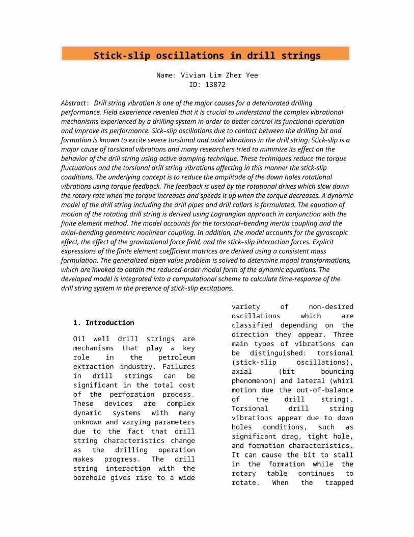
In this formulation, it is assumed that the material of the drill string is elastic, homogeneous and isotropic. The deflection of the drill string is produced by the displacement of points of the centerline. It is further assumed that internal damping and flow-induced forces are neglected at this stage. The finite element method is used to model the drill string used in rotational vertical drilling operations.
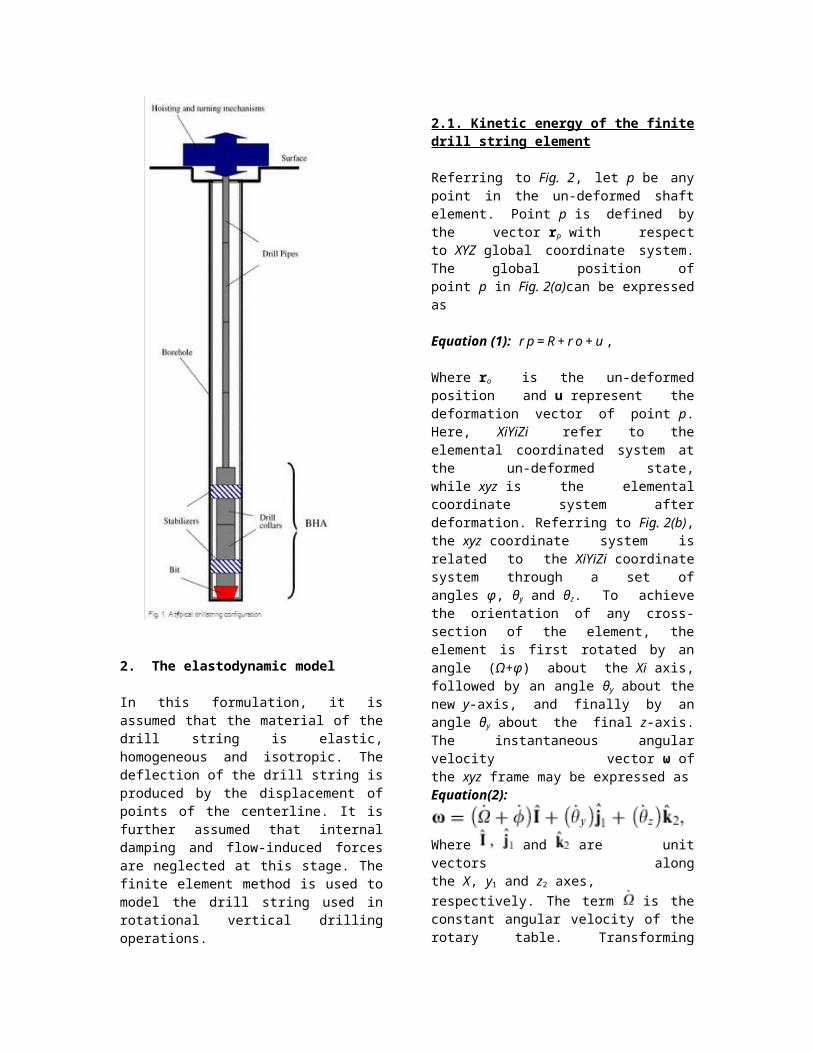
2.1. Kinetic energy of the finite drill string element
Referring to Fig. 2, let p be any point in the un-deformed shaft element. Point p is defined by the vector rp with respect to XYZ global coordinate system. The global position of point p in Fig. 2(a)can be expressed as
Equation (1): r p = R + r o + u ,
Where ro is the un-deformed position and u represent the deformation vector of point p. Here, XiYiZi refer to the elemental coordinated system at the un-deformed state, while xyz is the elemental coordinate system after deformation. Referring to Fig. 2(b), the xyz coordinate system is related to the XiYiZi coordinate system through a set of angles φ, θy and θz. To achieve the orientation of any cross-section of the element, the element is first rotated by an angle (Ω+φ) about the Xi axis, followed by an angle θy about the new y-axis, and finally by an angle θy about the final z-axis. The instantaneous angular velocity vector ω of the xyz frame may be expressed asEquation(2):
Where and are unit vectors along
the X, y1 and z2 axes, respectively. The term is the constant angular velocity of the rotary table. Transforming Eq. (2) into xyz coordinate and utilizing the linear approximation for the small angles θy and θy, one can, after some manipulations, express Eq. (2) in the following form:equation(3)
Since there is no change in R and ro when the element deforms, one can use the finite element notations to express the vector u asequation(4)u = N e ,
where N is the shape function matrix of the 3D finite beam element formulation, and e is the vector of nodal coordinates of the two-node finite string element, which is defined byequation(5)
Utilizing the assumed displacement field, the translational deformations of an element is represented in terms of shape functions as equation(6)
The elastic rotation of a typical cross section of the element is then approximated by
equation(7)
and for the torsional deformation of a typical cross section in the formequation(8)
Utilizing the time derivative of Eq. (4), the kinetic energy expression can be written asequation(9)
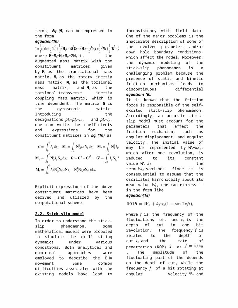
where ρ is the mass density and the matrix is the (3×3) skew-symmetric matrix associated with the rotational vector ω. The second and third terms in Eq. (9) are identically zero, because the moments of inertia are calculated with respect to the center of mass of the element. The first term represents the kinetic energy due to translation and the last term represents the kinetic energy due to rotational effects that include gyroscopic moments. Upon evaluating the first and last terms, Eq. (9) can be expressed in the formequation(10)
where M=Mt+Mr+Mϕ−2Me is the augmented mass matrix with the constituent matrices given by Mt as the translational mass matrix, Mr as the rotary inertia mass matrix, Mϕ as the torsional mass matrix, and Me as the torsional–transverse inertia coupling mass matrix, which is time dependent. The matrix G is the gyroscopic matrix. Introducing the designations ρIy=ρIy=ID, and ρIx=Ip, one can write the coefficients and expressions for the constituent matrices in Eq. (10) as
Explicit expressions of the above constituent matrices have been derived and utilized by the computational scheme.

2.2. Stick–slip model
In order to understand the stick–slip phenomenon, some mathematical models were proposed to simulate the drill string dynamics under various conditions. Both analytical and numerical approaches were employed to describe the BHA movement. Some common difficulties associated with the existing models have lead to inconsistency with field data. One of the major problems is the inaccurate description of some of the involved parameters and/or down hole boundary conditions, which affect the model. Moreover, the dynamic modeling of the stick–slip phenomenon is a challenging problem because the presence of static and kinetic friction mechanisms leads to discontinuous differential equations (6).It is known that the friction force is responsible of the self-excited stick–slip phenomenon. Accordingly, an accurate stick–slip model must account for the parameters that affect the friction mechanism; such as angular displacement, and angular velocity. The initial value of may be represented by Wo+kfxo, which after one revolution, is reduced to its constant value Wo as the term kfxo vanishes. Since it is consequential to assume that the oscillates harmonically about its mean value Wo, one can express it in the form likeequation(18)
where f is the frequency of the fluctuations of, and xo is the depth of cut in one bit revolution. The frequency f is related to the depth of cut xo and the rate of penetration (ROP) ,
as . The amplitude of the fluctuating part of the depends on the depth of cut, while the frequency f, of a bit rotating at angular
velocity and traveling at axial velocity , is calculated.
equation(19)
Accordingly, in this case, the term 2πft in Eq. (18) represents the torsional degree of freedom ϕ.In this analysis, it is assumed that the bit never loses contact with the formation. In addition, it is assumed that the bit is constrained in the lateral direction. In order to include the effect of axial
motion on the torsional oscillations, the coupling between axial degree of freedom and angular velocity is introduced in defining the torque term. As a result, torque-on-bit (TOB) is assumed to be dependent on, as
equation(20)
where μk is the coefficient of kinetic friction, and the torque in
Eq. (20) becomes . The
function relates TOB to the angular velocity of the bit. The experiments and field data records showed that the applied friction torque is proportional to the high fluctuations in the bit angular velocity. Unfortunately, there is no field data available to describe this relation at low velocities, and engineers usually perform extrapolation to plot the curve at low velocities. The concern about low velocity region relates to the fidelity of the stick–slip model at the region of transition from static to kinetic friction. However, at high velocities, all functions adopted in the aforementioned previous investigations tend to converge to a constant value.
In general, the adopted functions of may be classified as either continuous or discontinuous functions. The discontinuity in some proposed expressions posses a major source of computational difficulty, when it comes to numerical integration. A smooth
representation of over the short-lived transition event was adopted by several investigations, and was found to be rather accurate and computationally more efficient. A
continuous representation of , is given by Eq. (21) and employed in this investigationequation(21)
2.3. Equations of motion
By utilizing the above energy expressions into the variation form of Lagrange equation, and using the standard finite element assembly procedure, the equation of motion of the drill string can be written in the assembled general form as
equation(22)
where M is the global assembled mass matrix of the system, G is the gyroscopic matrix of the system, K is the global assembled stiffness matrix of the system, {e} is the deformation vector, and Q is the generalized force vector that accommodates the nonlinear inertia coupling terms, the TOB and other external excitations. The mass matrix M and the stiffness matrix K are symmetric, while the gyroscopic matrix G is skew-symmetric. The developed elastodynamic model does not account for damping. It is noteworthy to mention that damping is an important aspect to the dynamic behavior of drilling systems. In drilling applications, damping arises from structural material damping and viscous damping due to drilling mud interaction with the rotating drill string. Adding structural material damping is a straightforward task, and is often accounted for by an assumed linear model in the form of proportional modal damping, yet the elements of such damping matrices are merely rough estimates. Accordingly, adding damping may overshadow the clarity of insight gained by examining the un-damped system. However, viscous damping due to drilling fluid–structure interaction is more significant, and must be taken into account in a more comprehensive dynamic model. Studying the dynamics of drill strings in the presence of mud flow represents a problem of continued interest by some investigators.
3. The reduced-order model
In order to obtain the solution of the generalized eigenvalue associated with the homogenous equation of motion, one can represent Eq. (22) in the following state-space form [36] and [37]equation(23)
where for constant rotational speed of the drill string, the coefficient matrices of Eq. (23) are given by where for constant rotational speed of the drill string, the coefficient matrices of Eq. (23) are given by
The dimension of each of the matrices M, K and G is (6n×6n), where n is the number of nodes, while the matrices A and B are of dimension (12n×12n).In order to obtain the reduced order modal form, let R and L denote the right and left complex modal transformation matrices, respectively, which are associated with the differential operators of Eq. (14). Now, one can introduce the modal transformation y=Ru, where u is the vector of modal coordinates. In general, the modal matrices R and L are composed of a set of complex eigenvectors (mode shapes) that account for a selected set of significant modes. Pre-multiplying both sides of Eq. (23) by LT and substituting for y in terms of modal coordinates u, the truncated modal form of the equations of motion can be written asequation(24)
A r u + B r u = Q r ,
where Ar=LTAR and Br=LTBR represent the
reduced modal matrices, while is the reduced modal forcing vector.
4. Numerical results
A computational scheme is developed based on the presented formulation using MATLAB™. The presence of damping is known to stabilize the numerical integration. Although, damping is not present in this model, the integration scheme adopted herein is a high-order predictor-corrector algorithm with adaptive step size and optimized error control, which functions perfectly well even for un-damped systems. In this numerical demonstration, a drill string of the specifications given in Table 1 is considered. The results are obtained using the consistent mass FEM formulation with 24 finite shaft elements. This number of elements was found to achieve convergence for the chosen drill string configuration. Numerical tests showed that further increase of number of elements resulted in insignificant improvement in the calculated values. A total of 140 degrees of freedom is retained after applying the boundary conditions for the drill string system. The following discussion is primarily meant for a drill string in vertical borehole where no initial curvature is involved.
Table 1. Drill string dataDrill pipe specification
Drill pipe length 1000 m
Drill pipe outer diameter
0.127 m
Drill pipe inside diameter
0.095 m
Drill collar specification
Drill collar length 200 m
Drill collar outer diameter
0.2286 m
Drill collar inside diameter
0.0762 m
Material specification
Drill string density 7850 kg/m3
Modulus of elasticity
210×109 N/m2
Shear modulus 7.6923×10¹⁰ N/m2
4.1. Dynamic response analysis
The capability of the developed computational scheme is now tested for dynamic response calculations. The drill string transient response is obtained for two different excitations; initial displacement and an applied impulsive force. In order to calculate the transient response of the rotating drill string due to initial displacement, an admissible displacement field is considered. The initial displacement field is calculated by applying a force at approximately midway of drill pipe and calculating the nodal displacement from the static defection equation. The dynamic response of node 3 is shown in Fig. 3 for both the full-order and the reduced-order models. A fifth-order reduced model is obtained using the aforementioned modal transformation with the first five modes retained as significant modes. It is interesting to observe that a five-DOF reduced model gives a quite satisfactory response to that of 140-DOF full-order model.
Fig. 3. Transient response of node 3 due to initial displacement input (( ) full order and ( ) reduced order).
The response of the system due to an impulsive excitation is considered by subjecting the drill string to an initial velocity in the lateral direction of node 10 (the midpoint of the drill pipe). The response of node 3 is shown in Fig. 4 and Fig. 5, for two different reduced models. It is well-known in impact dynamics that impulsive forces tend to excite higher frequencies, thus engaging higher modes to share an appreciable amount of the system's kinetic energy. Consequently the reduced-order model needs to be expanded to include more significant modes. The 8-DOF reduced-order model in Fig. 5 is shown to approach the full-order solution more accurately than the 5-DOF model.
Fig. 4. Transient response of node 3 due to initial velocity (( ) full order and ( ) reduced order).
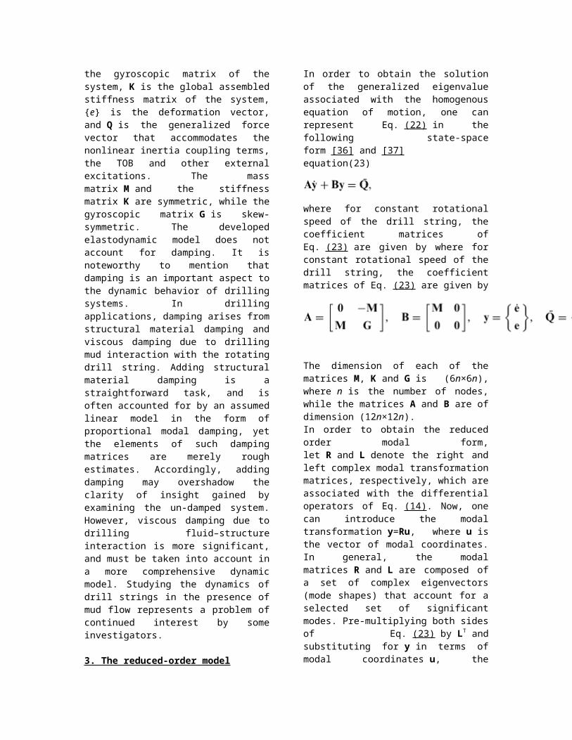
Fig. 5. Transient response of node 3 due to initial velocity (( ) full order and ( ) reduced order).
4.2. Dynamic response due to coupling
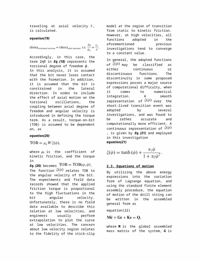
Secondly, the developed scheme is used to demonstrate the effect of coupling between axial–torsional–lateral structural vibrations of the drill string. Coupling could be a potential source of ambiguous vibrations in drill strings. It is essential to consider coupling while simulating real drilling systems in order for the model to adequately acquire a realistic insight of their dynamic behavior. In this numerical simulation, the time responses of the drill string system are evaluated under various lateral excitations to show their effects on axial and torsional directions. A 5-DOF reduced order model was employed in this case. Fig. 6, Fig. 7 and Fig. 8 show the axial response due to initial displacement, initial velocity and constant force in the lateral direction at node 10 (the midpoint of the drill pipe segment), respectively. In order to examine the severity of transverse excitations on the torsional behavior, several excitations were applied in the lateral direction to observe the consequent torsional response. Fig. 9, Fig. 10 and Fig. 11display the torsional responses, which are solely due to coupling with lateral motion in the absence of any torsional loads. This coupling may become even more significant if large lateral forces due drill string–borehole interaction, as well as higher values of WOB are encountered in normal drilling operations.
Fig. 6. Axial deflection due to lateral initial displacement.
Fig. 7. Axial deflection due to lateral velocity.
Fig. 8. Axial deflection due to lateral constant force.
Fig. 9. Torsional response due to lateral initial displacement.
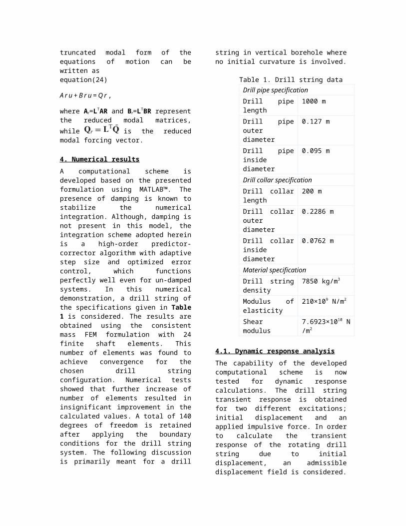
Fig. 10. Torsional response due to lateral initial velocity.
Fig. 11. Torsional response due to lateral constant force.
4.3. Stick–slip self-excited response
It has been established that friction torque is responsible for the severe stick–slip vibrations in drill strings. To obtain the drill string response due to friction torque excitation, an appropriate torque term is included in the forcing vector of the governing equation. The parameters used in this simulation represent a typical case in oil well drilling operations, and are given by W0=100 kN, kf=25,000 kN/m, xo=0.001 m, μk=0.04,α1=2, and α2=1. Fig. 12 and Fig. 13 show the drill string angular speed at the surface (rotary table) and at 200-m above the bit, respectively. Fig. 14 shows the instantaneous bit angular speed over a period of 20 s of fully developed stick–slip while drilling. The mean angular speed of the rotary table is 110 rev/min (10.5 rad/s), which is constant over time while the bit is oscillating between a complete standstill, and a very high velocity that reaches about three times the surface velocity. This is in agreement with field measurements, which have shown that when there are significant torsional vibrations, the bit speed differs from the rotary
table speed by as much as three times, as reported by previous investigations.
Fig. 12. Torsional stick–slip oscillation at the rotary table.
Fig. 13. Torsional stick–slip oscillation at 200-m above the bit.
Fig. 14. Torsional stick–slip oscillation at the drilling bit.
Another important parameter to be investigated in stick–slip problems is the developed torque profile. The fluctuations of torque could be very detrimental to the drilling bit and down hole equipment. Typical torque evolution during stick–slip oscillation is shown in Fig. 15. During

slip phase, there are periodic fluctuations in the torque profile around the mean value 5000 N m. The amplitude of this fluctuation is relatively small but the fluctuation frequency is high. Suddenly, the toque mean value drops to minimum value, which indicates that the bit is about to stick. In the stick regime, the bit momentarily stops causing the top torque and TOB to build up in almost linear fashion to reach very large value.
Fig. 15. Torque on bit profile for stick–slip oscillations (full-order model).
Stick–slip oscillation as experienced in drilling process is an example of limit-cycling behavior. To demonstrate this behavior, the trajectory of the bit displacement relative to the rotary table versus the bit instantaneous velocity is obtained in Fig. 16. The initial bit speed is 110 RPM which is same as rotary speed. A straight line at zero speed represents the stick phase. During slip phase, the velocity increases while the displacement returns back to its equilibrium position. In Fig. 16, the zero value on the displacement axis represents the location of the rotary table. The region to the left side of this point (negative displacement) implies that bit is lagging behind the rotary table. Positive values of the displacement indicate that the bit is leading the rotary table at this region; i.e. the instantaneous speed of the bit is greater than the rotary speed.
Fig. 16. Phase plane of the bit during stick–slip oscillations (full-order model).
5. Conclusions
A finite element dynamic formulation of the vibrational characteristics of rotating drill string is developed. The model accounts for the gyroscopic, as well as the axial/bending, bending/torsional coupling, and the stick–slip interaction. In addition, the axial gravitational field effect on the drill string, which was ignored by other FEM formulations, has been considered. Complex modal transformations are applied and reduced-order models are obtained. The finite element formulation is then integrated into a computational scheme for calculating the natural frequencies of the whole drill string. The computational scheme is extended further to integrate the equations of motion, either in the full-order or the reduced-order form, to obtain the dynamic response. Numerical demonstrations using different excitations are considered to validate the model, and some benchmark solutions are presented. The results obtained are in excellent agreement with actual field observations and measurements. The method developed in this paper is intended to furnish the basic building block for further development of more comprehensive drilling assembly models that can easily accommodate other related dynamic effects resulting from wellbore/drill pipe contact and drill string/mudflow interaction. Research is currently underway by the authors, both analytically and experimentally, to extend the developed model to include the related dynamic effects of string/borehole interaction and the effect of damping due to the drilling mud flow.
References
[1] J.J. Bailey, I. FinnieAn analytical study of drillstring vibrationJournal of Engineering for Industry, ASME Transaction, 82 (2) (1960), pp. 122–128
[2] I. Finnie, J.J. BaileyAn experimental study of drillstring vibrationJournal of Engineering for Industry, ASME Transaction, 82 (2) (1960), pp. 129–135
[3] D.W. Dareing, B.J. LivesayLongitudinal and angular drillstring vibrations with dampingJournal of Engineering for Industry, ASME Transaction, November (1968), pp. 671–679
[4] L.F. Kreisle, J.M. VanceMathematical analysis of the effect of shock sub on the longitudinal vibrations of an oilwell drillstringSPE, December (1970), pp. 349–356
[5] I.G. Eronini, W.H. Somerton, D.M. AuslanderA dynamic model for rotary rock drillingEnergy Resources Technology, June (1982), pp. 108–120
[6] R.I. Leine, D.H. Van Campen, L. van den SteenStick–slip vibrations induced by alternate friction modelsNonlinear Dynamics, 16 (1998), pp. 41–54
[7] G.w. Halsey, A. Kyllingstad, T.V. Aarrestad, D. Lysne, Drillstring torsional vibrations: comparison between theory and experiment on a full-scale research drilling rig, SPE 15564, Proceedings of the SPE Annual Technical Conference and Exhibition, New Orleans, October 5–8, 1986.
[8]N. Challamel, E. Sellami, E. Chenevez, L. Gossuin, A stick–slip analysis based on rock/bit interaction: theoretical and experimental contribution, SPE 59230. Presented at the IADC/SPE Drilling Conference, Orleans, LA, 2000.
[9]R. Dawson, Y.Q. Lin, P.D. Spanos, Drillstring stick–slip oscillations, Proceedings of the Spring Conference of the Society for Experimental Mechanics, Houston, TX, 1987.
[10] Y.Q. Lin, Y.H. WangStick–slip vibration of the drill stringsJournal of Engineering for Industry, ASME Transaction, Series B, 113 (1991), pp. 38–49
[11] J.F. Brett, The genesis of bit-induced torsional drill string vibrations, SPE 21943, Proceedings of the SPE/IADC Drilling Conference, Amsterdam, March 11–14, 1991.
[12] J.D. Jansen, L. van den SteenActive damping of self-excited torsional vibration in oil well drillstringsJournal of Sound and Vibration, 179 (1995), pp. 647–668
[13] T. Richard, E. DetournayStick–slip vibrations of PDC bitsPacific Rocks (2000), pp. 33–40
1.[14] T. Richard, E. DetournaySelf-excited stick–slip vibrations of drill bitsComptes Rendus de l Mecanique, 332 (2004), pp. 619–626
[15] R.W. Tucker, C. WangOn the effective control of torsional vibrations in drilling systemsJournal of Sound and Vibration, 224 (1999), pp. 101–122
[16]A. Leseultre, E. Lamine, A. Jonsson, An Instrumented Bit: A necessary step to the intelligent BHA, SPE 39341, Proceedings of the IADC/SPE Drilling Conference, Dallas, TX, 1998.
[17] R.I. Leine, D.H. Van Campen, W.J. KeultjesStick–slip whirl interaction in drillstring dynamicsJournal of Sound and Acoustics, 124 (2002), pp. 209–220 [18]A.S. Yigit, A.P. ChristoforouCoupled axial and transverse vibrations of oilwell drillstrings

Journal of Sound and Vibration, 195 (4) (1996), pp. 617–627