Vibration Analysis of Machine Tool Spindle Systems: A ...
6
1 Copyright © 2014 by ASME VIBRATION ANALYSIS OF MACHINE TOOL SPINDLE SYSTEMS: A CALIBRATED FINITE ELEMENT MODEL Seyed M. Hashemi Professor, Dept. of Aerospace Eng., Ryerson University Toronto, ON, Canada Hemachandran Sambandamurthy Graduate Student, Dept. of Aerospace Eng., Ryerson University Toronto, ON, Canada Hamid Ghaemi Adjunct Professor, Dept. of Aerospace Eng., Ryerson University Toronto, ON, Canada ABSTRACT The effects of spindles vibrational behavior on the stability lobes and the chatter behavior of machine tools have been established, and the service life has been observed to reduce the system natural frequencies. In this paper, a ‘calibrated’ FEM model of the spindle system, where the bearings are modeled as linear spring elements, is introduced. The numerical models of a sample spindle system are developed in ANSYS ® software using BEAM188 and SOLID187 elements. COMBIN14 elements are used to model the bearings; by varying the spring constant value of these elements the spindle’s fundamental frequency is tuned to match the nominal value, also verified experimentally. The beam element-based model is observed to converge faster than the one based on solid elements. The uncalibrated frequencies resulting from latter model are also found to be lower than those obtained from the former one, which could be associated with the shear/rotary inertia effects present in the SOLID187 element. INTRODUCTION The need for air transportation has increased drastically over the last decades, and as a result, manufacturing companies are trying to improve and speed up their machining processes to cope with these increasing demands. High precision in surface finish is required in components manufactured for aerospace applications. To achieve higher production rates, the cycle time- time required for a part or component to be machined- should be reduced. However, chatter often poses a limiting factor on the achievable productivity. One of the major parameters contributing to chatter is the fundamental frequency of the machining system. The natural frequency of the cutting system, comprised of the spindle, shaft, tool and hold combination, is then used to generate the stability lobes. The resulting graph has a series of lobes intersecting each other at certain points. The area formed underneath and above the intersection of these lobes represents stable and unstable machining conditions, respectively. A reliable stability lobe - axial depth of cut vs. spindle speed - can only be constructed if the system’s natural frequency is accurately evaluated. Impact test is commonly used to determine frequency response function (FRF), which in turn is utilized to acquire the natural frequencies of the cutting system. However, frequent impact testing at each stage of machining is impractical, as it will hinder production. An offline method of obtaining the FRF could greatly benefit manufacturing companies by eliminating the downtime needed for the impact test. Adetoro et al. [1] suggested that the whole system comprising machine, tool and work piece could be modeled using finite element analysis. A computer simulation would be able to predict the FRF during all phases of the machining process. Most existing research papers assume that the FRF remains constant throughout the whole process. However, a constantly updated FRF would allow for accurate, real time stability calculations. Also, to the authors’ best knowledge, the spindle decay/bearings wear over the service time and their effects on the system natural frequencies, and consequently change of the stability lobes, have not been investigated. The objective of the present study is to determine the natural frequencies/vibration characteristics of machine tool spindle systems by developing its FEM model and the proper boundary conditions. These results would then be compared to the existing results for a common cutting system to validate/tune the model developed. The bearings are first modeled as Simply-Supported (S-S), which are then replaced by linear spring elements to incorporate the flexibility of bearings into the model. In comparison with the existing data on the spindle’s fundamental frequency, the bearing stiffness coefficient, K S , is then varied to achieve a Calibrated FEM vibrational model. Such a model would help to establish the relationship between the system characteristics, incorporating spindle’s age, and the optimal machining parameters. Proceedings of the ASME 2014 International Mechanical Engineering Congress and Exposition IMECE2014 November 14-20, 2014, Montreal, Quebec, Canada IMECE2014-39547
Transcript of Vibration Analysis of Machine Tool Spindle Systems: A ...
1 Copyright © 2014 by ASME
VIBRATION ANALYSIS OF MACHINE TOOL SPINDLE SYSTEMS: A CALIBRATED FINITE ELEMENT MODEL
Seyed M. Hashemi Professor,
Dept. of Aerospace Eng., Ryerson University
Toronto, ON, Canada
Hemachandran Sambandamurthy Graduate Student,
Dept. of Aerospace Eng., Ryerson University
Toronto, ON, Canada
Hamid Ghaemi Adjunct Professor,
Dept. of Aerospace Eng., Ryerson University
Toronto, ON, Canada
ABSTRACT The effects of spindles vibrational behavior on the stability
lobes and the chatter behavior of machine tools have been established, and the service life has been observed to reduce the system natural frequencies. In this paper, a ‘calibrated’ FEM model of the spindle system, where the bearings are modeled as linear spring elements, is introduced. The numerical models of a sample spindle system are developed in ANSYS® software using BEAM188 and SOLID187 elements. COMBIN14 elements are used to model the bearings; by varying the spring constant value of these elements the spindle’s fundamental frequency is tuned to match the nominal value, also verified experimentally. The beam element-based model is observed to converge faster than the one based on solid elements. The uncalibrated frequencies resulting from latter model are also found to be lower than those obtained from the former one, which could be associated with the shear/rotary inertia effects present in the SOLID187 element.
INTRODUCTION The need for air transportation has increased drastically
over the last decades, and as a result, manufacturing companies are trying to improve and speed up their machining processes to cope with these increasing demands. High precision in surface finish is required in components manufactured for aerospace applications. To achieve higher production rates, the cycle time- time required for a part or component to be machined- should be reduced. However, chatter often poses a limiting factor on the achievable productivity. One of the major parameters contributing to chatter is the fundamental frequency of the machining system. The natural frequency of the cutting system, comprised of the spindle, shaft, tool and hold combination, is then used to generate the stability lobes. The resulting graph has a series of lobes intersecting each other at certain points. The area formed underneath and above the intersection of these lobes represents stable and unstable
machining conditions, respectively. A reliable stability lobe - axial depth of cut vs. spindle speed - can only be constructed if the system’s natural frequency is accurately evaluated. Impact test is commonly used to determine frequency response function (FRF), which in turn is utilized to acquire the natural frequencies of the cutting system. However, frequent impact testing at each stage of machining is impractical, as it will hinder production.
An offline method of obtaining the FRF could greatly benefit manufacturing companies by eliminating the downtime needed for the impact test. Adetoro et al. [1] suggested that the whole system comprising machine, tool and work piece could be modeled using finite element analysis. A computer simulation would be able to predict the FRF during all phases of the machining process. Most existing research papers assume that the FRF remains constant throughout the whole process. However, a constantly updated FRF would allow for accurate, real time stability calculations. Also, to the authors’ best knowledge, the spindle decay/bearings wear over the service time and their effects on the system natural frequencies, and consequently change of the stability lobes, have not been investigated.
The objective of the present study is to determine the natural frequencies/vibration characteristics of machine tool spindle systems by developing its FEM model and the proper boundary conditions. These results would then be compared to the existing results for a common cutting system to validate/tune the model developed. The bearings are first modeled as Simply-Supported (S-S), which are then replaced by linear spring elements to incorporate the flexibility of bearings into the model. In comparison with the existing data on the spindle’s fundamental frequency, the bearing stiffness coefficient, KS, is then varied to achieve a Calibrated FEM vibrational model. Such a model would help to establish the relationship between the system characteristics, incorporating spindle’s age, and the optimal machining parameters.
Proceedings of the ASME 2014 International Mechanical Engineering Congress and Exposition IMECE2014
November 14-20, 2014, Montreal, Quebec, Canada
IMECE2014-39547

2 Copyright © 2014 by ASME
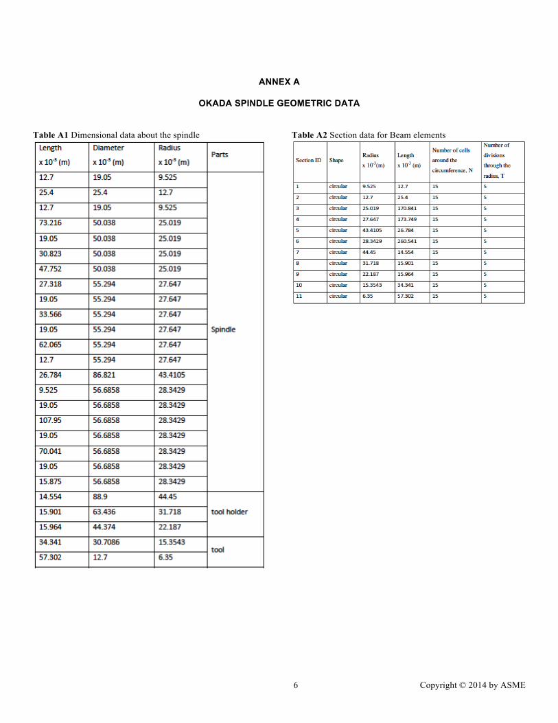
The spindle of the OKADA VM 500, which is a vertical milling machine, was modeled using CATIA® V5. The schematic structure of the spindle is shown in Figure 1. The spindle has a total of 10 bearings, with four sets of angular contact bearings and two other ball bearings. Apart from that, it has two belt assemblies, which provides the necessary driving force from the spindle motor. The dimensions of the spindle were measured and recorded, as shown in Annex A. For the sake of modeling convenience, the tapered and curved areas of the spindle and tool were modeled as uniform areas. The spindle along with the tool holder and tool were modeled as a single rigid system as shown in Figure 2.
Figure 1 Schematic diagram of OKADA VM500 spindle [2]
Figure 2 Spindle modeled in CATIA® V5
The spindle model generated in CATIA® V5 was imported
to ANSYS® Academic Research, Release 14.5, one of the widely used commercial analytical software for performing finite element analysis. After importing the model, the desired boundary conditions were applied and the model was meshed. This was followed by modal analysis, which gives the natural frequency of the system. In modal analysis, the model was constraint and zero-bound (absence of external load) was the only load condition. In this analysis, simply supported boundary conditions were first applied at the bearing locations and they were later modified to COMBIN14 elements. Beam elements and solid elements were used to model the spindle individually.
The spindle was modeled using beam elements [3], as it is the most effective way of representing the spindle. The line element, BEAM188 has 2 nodes and 6 degrees-of-freedom (3 translational and 3 rotational), requires cross-sectional details for modeling [4], provided in Annex A. The material property of tool steel was used in the model. The young’s modulus, E=210 GPa and density, ρ = 7850 Kg/m3 was applied. At first, simply-supported boundary conditions were applied at the bearing locations. Modal analysis was carried out and the first six natural frequencies of the spindle system are tabulated in Table 1.
Table 1 Natural Frequencies of the non-spinning spindle using Beam 188 element and simply-supported boundary condition
From Table 1 it can be seen that the first/second, third/fourth and fifth/sixth natural frequencies are similar. They are mutually orthogonal and constitute the bending lateral vibrations along Y- and Z-axis. Convergence study was conducted to find the least number of elements needed to obtain acceptable results, as shown in Figure 3. The model was meshed finer each time and the results obtained were recorded. From Table 1 and Figure 3, it can be seen that the 5th natural frequency remains at 3780.8 Hz after 66 elements and does not change even after 154 elements. Therefore, the appropriate number of elements required to obtain the result was considered to be 66 elements.
Figure 3 Convergence test for the 5th flexural frequency of the spindle system using Beam188, with S-S boundary condition.
The boundary condition at the bearing locations were then
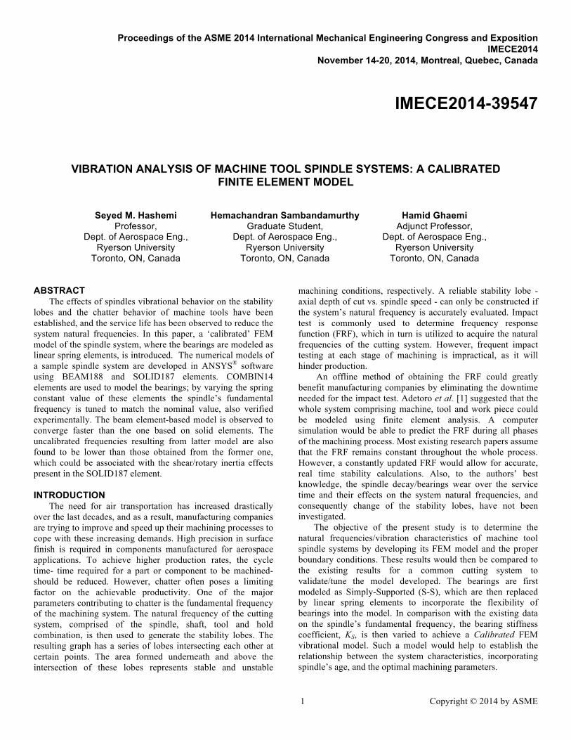
modified from S-S to spring-damper COMBIN14 element, where the spring constant value, ‘k’ can be modified (Figure 4). By changing the spring constant value, the spindle model was tuned to its nominal natural frequency. Four spring-damper elements were used in every bearing location. At the bearing location, the rotational and translational degree of freedom along the Y- and Z-axis was constrained by the spring-damper element. The various values of the spring constant leading to the natural frequency of the spindle are given in Table 2. At k=1.5e8 (N/m), the natural frequency reported by the manufacturer was obtained. It was observed that as the spring stiffness value increases, the natural frequency also increases. The spindle was not constrained along its longitudinal
3 Copyright © 2014 by ASME
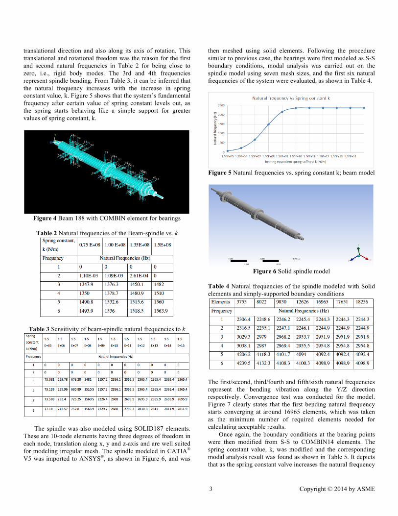
translational direction and also along its axis of rotation. This translational and rotational freedom was the reason for the first and second natural frequencies in Table 2 for being close to zero, i.e., rigid body modes. The 3rd and 4th frequencies represent spindle bending. From Table 3, it can be inferred that the natural frequency increases with the increase in spring constant value, k. Figure 5 shows that the system’s fundamental frequency after certain value of spring constant levels out, as the spring starts behaving like a simple support for greater values of spring constant, k.
Figure 4 Beam 188 with COMBIN element for bearings
Table 2 Natural frequencies of the Beam-spindle vs. k
Table 3 Sensitivity of beam-spindle natural frequencies to k
The spindle was also modeled using SOLID187 elements. These are 10-node elements having three degrees of freedom in each node, translation along x, y and z-axis and are well suited for modeling irregular mesh. The spindle modeled in CATIA®
V5 was imported to ANSYS®, as shown in Figure 6, and was
then meshed using solid elements. Following the procedure similar to previous case, the bearings were first modeled as S-S boundary conditions, modal analysis was carried out on the spindle model using seven mesh sizes, and the first six natural frequencies of the system were evaluated, as shown in Table 4.
Figure 5 Natural frequencies vs. spring constant k; beam model
Figure 6 Solid spindle model
Table 4 Natural frequencies of the spindle modeled with Solid elements and simply-supported boundary conditions
The first/second, third/fourth and fifth/sixth natural frequencies represent the bending vibration along the Y/Z direction respectively. Convergence test was conducted for the model. Figure 7 clearly states that the first bending natural frequency starts converging at around 16965 elements, which was taken as the minimum number of required elements needed for calculating acceptable results. Once again, the boundary conditions at the bearing points were then modified from S-S to COMBIN14 elements. The spring constant value, k, was modified and the corresponding modal analysis result was found as shown in Table 5. It depicts that as the spring constant valve increases the natural frequency
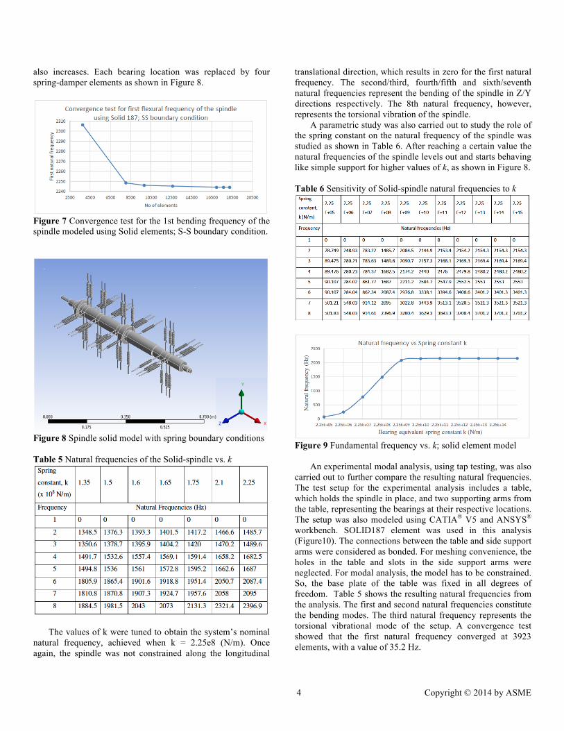
4 Copyright © 2014 by ASME
also increases. Each bearing location was replaced by four spring-damper elements as shown in Figure 8.
Figure 7 Convergence test for the 1st bending frequency of the spindle modeled using Solid elements; S-S boundary condition.
Figure 8 Spindle solid model with spring boundary conditions Table 5 Natural frequencies of the Solid-spindle vs. k
The values of k were tuned to obtain the system’s nominal natural frequency, achieved when k = 2.25e8 (N/m). Once again, the spindle was not constrained along the longitudinal
translational direction, which results in zero for the first natural frequency. The second/third, fourth/fifth and sixth/seventh natural frequencies represent the bending of the spindle in Z/Y directions respectively. The 8th natural frequency, however, represents the torsional vibration of the spindle. A parametric study was also carried out to study the role of the spring constant on the natural frequency of the spindle was studied as shown in Table 6. After reaching a certain value the natural frequencies of the spindle levels out and starts behaving like simple support for higher values of k, as shown in Figure 8. Table 6 Sensitivity of Solid-spindle natural frequencies to k
Figure 9 Fundamental frequency vs. k; solid element model
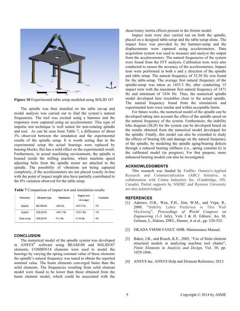
An experimental modal analysis, using tap testing, was also
carried out to further compare the resulting natural frequencies. The test setup for the experimental analysis includes a table, which holds the spindle in place, and two supporting arms from the table, representing the bearings at their respective locations. The setup was also modeled using CATIA® V5 and ANSYS® workbench. SOLID187 element was used in this analysis (Figure10). The connections between the table and side support arms were considered as bonded. For meshing convenience, the holes in the table and slots in the side support arms were neglected. For modal analysis, the model has to be constrained. So, the base plate of the table was fixed in all degrees of freedom. Table 5 shows the resulting natural frequencies from the analysis. The first and second natural frequencies constitute the bending modes. The third natural frequency represents the torsional vibrational mode of the setup. A convergence test showed that the first natural frequency converged at 3923 elements, with a value of 35.2 Hz.
5 Copyright © 2014 by ASME
Figure 10 Experimental table setup modeled using SOLID 187
The spindle was then installed on the table set-up and modal analysis was carried out to find the system’s natural frequencies. The tool was excited using a hammer and the responses were captured using an accelerometer. This type of impulse test technique is well suited for non-rotating spindle and tool. As can be seen from Table 7, a difference of about 3% observed between the simulation and the experimental results of the spindle setup. It is worth noting that in the experimental setup the actual bearings were replaced by bearing blocks; this has a mild effect on the experimental result. Furthermore, in actual machining environment, the spindle is housed inside the milling machine, where machine speed adjusting belts from the spindle motor are attached to the spindle. The possibility of vibrations not being captured completely, if the accelerometers are not placed exactly in-line with the point of impact might also have partially contributed to the 8% variation observed for the table setup. Table 7 Comparison of impact test and simulation results
CONCLUSION The numerical model of the spindle system was developed
in ANSYS® software using BEAM188 and SOLID187 elements. COMBIN14 elements were used to model the bearings by varying the spring constant value of these elements the spindle’s natural frequency was tuned to obtain the reported nominal value. The beam elements converged faster than the solid elements. The frequencies resulting from solid element model were found to be lower than those obtained from the beam element model, which could be associated with the
shear/rotary inertia effects present in the former model. Impact tests were also carried out on both the spindle,
placed on a designed table-setup and the table-setup alone. The impact force was provided by the hammer-setup and the displacements were captured using accelerometers. Data acquisition system was used to measure and analyze the output from the accelerometers. The natural frequencies of the system were found from the FFT analysis. Calibration tests were also conducted to ensure the accuracy of the accelerometers. Impact tests were performed in both x and y direction of the spindle and table setup. The natural frequency of 32.58 Hz was found for the table-setup. The average first natural frequency of the spindle-setup was taken as 1453.5 Hz, after conducting 15 impact tests with the maximum first natural frequency of 1471 Hz and minimum of 1436 Hz. Thus, the numerical spindle model developed here resembles close to the actual spindle. The natural frequency found from the simulations and experimental tests were similar and within acceptable limits.
For future works, the numerical model of the spindle can be developed taking into account the effect of the spindle speed on the natural frequency of the system. Furthermore, the stability lobe diagram (SLD) for the system can be developed based on the results obtained from the numerical model developed for the spindle. Finally, this model can also be extended to study the effects of bearing life and damage on the natural frequency of the spindle, by modeling the spindle aging/bearing defects through a reduced bearing stiffness (i.e., spring constant k) in the calibrated model (in progress). For that purpose, more enhanced bearing models can also be investigated.
ACKNOWLEDGMENTS This research was funded by FedDev Ontario's Applied
Research and Commercialization (ARC) Initiative, in collaboration with Centra Industries Inc. (Cambridge, ON, Canada). Partial supports by NSERC and Ryerson University are also acknowledged.
REFERENCES [1] Adetoro, O.B., Wen, P.H., Sim, W.M., and Vepa, R.,
2009, “Stability Lobes Prediction in Thin Wall Machining”, Proceedings of World Congress on Engineering (1-3 July), Vols I & II. Editors: Ao, SI, Gelman, L, Hukins, DWL, Hunter, A et al., pp. 520-525.
[2] OKADA VM500 FANUC 6MB. Maintenance Manual. [3] Baker, J.R., and Rouch, K.E., 2002, “Use of finite element
structural models in analyzing machine tool chatter”, Finite Elements in Analysis and Design, Vol. 38, pp. 1029-1046.
[4] ANSYS Inc. ANSYS Help and Element Reference, 2013.
6 Copyright © 2014 by ASME
ANNEX A
OKADA SPINDLE GEOMETRIC DATA
Table A1 Dimensional data about the spindle
Table A2 Section data for Beam elements