
VIBRATING LEVEL INDICATOR SCHWINGUNGS … · S.p.A. Il Sistema Qualità aziendale, ... grado di...
15
ILV • VIBRATING LEVEL INDICATOR • SCHWINGUNGS-FÜLLSTANDMELDER • INDICATEUR DE NIVEAU A VIBRATION • INDICATORE DI LIVELLO A VIBRAZIONE CATALOGUE No. TO.920 ISSUE A3 LATEST UPDATE 05.09 CIRCULATION 100 Pneutrol International limited, 5 Caulside Drive, Antrim, Northern Ireland, BT41 2DU www.pneutrolspares.com, [email protected], Tel +44 (0) 28 9448 1800
Transcript of VIBRATING LEVEL INDICATOR SCHWINGUNGS … · S.p.A. Il Sistema Qualità aziendale, ... grado di...

ILV
• VIBRATING LEVEL INDICATOR
• SCHWINGUNGS-FÜLLSTANDMELDER
• INDICATEUR DE NIVEAU A VIBRATION
• INDICATORE DI LIVELLO A VIBRAZIONE
CATALOGUE No. TO.920
ISSUEA3
LATEST UPDATE05.09
CIRCULATION100
Pneutrol International limited, 5 Caulside Drive, Antrim, Northern Ireland, BT41 2DU www.pneutrolspares.com, [email protected], Tel +44 (0) 28 9448 1800

Tous les produits décrits dansce catalogue ont été réalisé se-lon les modalités opérationnel-les définies Système de Qua-lité de TOREX S.p.A.
Le système de Qualité de l’en-treprise, est en mesure d’assu-rer que le procédé entier de pro-duction, à partir de la formula-tion de la commande jusqu’auservice technique après la livrai-son, soit effectué de manièrecontrôlée et appropriée afin degarantir le standard de qualitédu produit.
Tutti i prodotti descritti in questocatalogo sono stati realizzati se-condo modalità operative defi-nite Sistema Qualità di TOREXS.p.A.
Il Sistema Qualità aziendale, cer-tificato nel Luglio 2004 in con-formità con le normative inter-nazionali ISO 9001:2000 è ingrado di assicurare che l’interoprocesso produttivo, dalla for-mulazione dell’ordine fino all’as-sistenza tecnica successivaalla consegna, venga effettua-to in modo controllato ed ade-guato a garantire lo standardqualitativo del prodotto.
All the products described inthis catalogue are manufacturedaccording to TOREX S.p.A.Quality System procedures.
The Company’s Quality System,starting from the processing ofthe order to the technical serv-ice after delivery, is carried outin a controlled manner that guar-antees the quality standard ofthe product.
Alle in diesem Katalog beschrie-benen Erzeugnisse werden inKonformität mit dem Qualitäts-system der TOREX S.p.A.hergestellt.
Das im Juli 1994 zertifizierteQualitätssystem entspricht derNorm UNI EN ISO 9002-94 (imOktober 2002 auf UNI EN ISO9001-2000 erweitert) und ge-währleistet dem Kunden einestrenge Qualitätskontrolle in je-der Phase des Produktionpro-zesses bis hin zum Kunden-dienst nach Auslieferung derWare.
Abweichungen infolge Ände-rungen und/oder aufgrund vonFertigungstoleranzen sind vor-behalten.
Nous nous réservons des écar-tements éventuels dûs des mo-difications et/ou des tolérancesd’usinage.
Ci riserviamo eventuali scosta-menti dovuti a modifiche e/o tol-leranze di lavorazione.
Possible deviations due to modi-fications and/or manufacturingtolerances are reserved.

INDEX
INHALTSVERZEICHNIS
INDEX
INDICE
05.09
TO.920 .INDEX
-
-
--
ILV
TECHNICAL CATALOGUEINTRODUCTION...........................................................................EXAMPLE OF APPLICATIONS..........................................................GENERAL LAYOUT........................................................................OPERATING CONDITIONS.............................................................ORDER CODES............................................................................DIMENSIONS...............................................................................ACCESSORIES.............................................................................ORDER FORM..............................................................................
2
1 TECHNICAL CATALOGUEEINFÜHRUNG..................................................................ANWENDUNGSBEISPIELE..................................................HAUPTSCHALTPLAN...........................................................BETRIEBSBEDINGUNGEN...................................................BESTELLCODES.................................................................ABMESSUNGEN................................................................ZUBEHÖR.........................................................................AUFTRAGSFORMULAR........................................................
MAINTENANCE CATALOGUEINTRODUCTION............................................................................BUT ET IMPORTANCE DU MANUEL.................................................WARRANTY CONDITIONS..............................................................WARNING.....................................................................................PACKAGING AND WEIGHTS............................................................UNLOADING AND HANDLING.........................................................STORAGE.....................................................................................INSTALLATION - APPLICATION........................................................INSTALLAZION - SAFETY................................................................INSTALLATION - MECHANICAL CONNECTIONS................................INSTALLATION - ELECTRICAL CONNECTIONS.................................INDICATOR ADJUSTMENT..............................................................MAINTENANCE..............................................................................CLEANING....................................................................................NOISE-SCRAPPING.......................................................................RESIDUAL RISKS..........................................................................
CATALOGUE D’ENTRETIENINTRODUCTION............................................................................BUT ET IMPORTANCE DU MANUEL.................................................CONDITIONS DE GARANTIE...........................................................RECOMMANDATIONS....................................................................EMBALLAGE ET POIDS...................................................................DECHARGEMENT ET MANUTENTION..............................................EMMAGASINAGE............................................................................MISE EN PLACE - APPLICATION.....................................................MISE EN PLACE - SECURITE..........................................................INSTALLATION - RACCORDEMENTS MÉCANIQUES...........................INSTALLATION - RACCORDEMENTS ELECTRIQUES..........................REGLAGE INDICATEUR..................................................................ENTRETIEN..................................................................................NETTOYAGE..................................................................................BRUIT - DEMANTELEMENT..............................................................RISQUES RESIDUELS...................................................................
WARTUNGSKATALOGEINFÜHRUNGZWECK UND BEDEUTUNG DES HANDBUCHS........................GARANTIEBEDINGUNGEN..................................................HINWEISE............................................................................VERPAKUNG UND GEWICHTE...............................................VABLADEN UND HANDLING..................................................LAGERHALTUNG....................................................................INSTALLATION - ANWENDUNG...............................................INSTALLATION - SICHEREIT...................................................INSTALLATION - MECHANISCHE ANSCHLÜSSE.......................INSTALLATION - ELEKTRISCHE ANSCHLÜSSE.........................EINSTELLUNG DES MELDERS...............................................WARTUNGSANLEITUNG........................................................REINIGUNG..........................................................................LÄRM - VERSCHROTTUNG.....................................................RESTRISIKEN.......................................................................
CATALOGO DI MANUTENZIONEINTRODUZIONE...................................................................SCOPO E IMPORTANZA DEL MANUALE...................................CONDIZIONI DI GARANZIAAVVERTENZEIMBALLO E PESI....................................................................SCARICO E MOVIMENTAZIONEIMMAGAZZINAGGIO...............................................................INSTALLAZIONE - APPLICAZIONEINSTALLAZIONE - SICUREZZAINSTALLAZIONE - COLLEGAMENTI MECCANICIINSTALLAZIONE - CONNESSIONI ELETTRICHEREGOLAZIONE INDICATOREMANUTENZIONEPULIZIA................................................................................RUMORE ROTTAMAZIONE......................................................RISCHI RESIDUI...................................................................
T. 01. 02. 03. 04→. 07. 08→. 09. 10→. 11. 12. 13→. 16
CATALOGO TECNICOINTRODUZIONE............. ...............................................ESEMPI DI APPLICAZIONE..................................................SCHEMA GENERALE...........................................................CONDIZIONI DI FUNZIONAMENTO......................................CODICI DI SCELTA..............................................................DIMENSIONI......................................................................ACCESSORI.......................................................................MODULO D’ORDINE...........................................................
CATALOGUE TECNIQUEINTRODUCTION............................................................................EXEMPLES D’APPLICATION............................................................SCHÉMA GÉNÉNERAL...................................................................CONDITIONS DE FONCTIONNEMENT..............................................CODES DE SELECTION.................................................................DIMENSIONS................................................................................ACCESSOIRES.............................................................................FORMULAIRE DE COMMANDE.......................................................
M. 01. 02. 03. 04. 05. 06. 07. 08→. 12. 13. 14. 15→. 16. 17→. 18. 19→. 20. 21. 22. 23
CATALOGUE PIECES DE RECHANGEPIECES DE RECHANGE.................................................................
CATALOGO RICAMBIPEZZI DI RICAMBIO.............................................................
SPARE PARTS CATALOGUESPARE PARTS................................................................................
ERSATZTEILKATALOGERSATZTEIL.................................................................................R. 01
3
R. 01
M. 01. 02. 03. 04. 05. 06. 07. 08→. 12. 13. 14. 15→. 16. 17→. 18. 19→. 20. 21. 22. 23
T. 01. 02. 03. 04→. 07. 08→. 09. 10→. 11. 12. 13→. 16


1TE
CH
NIC
AL
CAT
ALO
GU
EA
ll rig
hts
rese
rved
© W
AM
GR
OU
P
• VIBRATING LEVEL INDICATORTECHNICAL CATALOGUE
• SCHWINGUNGS-FÜLLSTANDMELDERTECHNISCHER KATALOG
• INDICATEUR DE NIVEAU A VIBRATIONCATALOGUE TECHNIQUE
• INDICATORE DI LIVELLO A VIBRAZIONECATALOGO TECNICO
ILV
CATALOGUE No. TO.920 T.
ISSUEA3
LATEST UPDATE05.09
CIRCULATION100

-
-
-
-
05.09
1TO.920.T.
ILV
INTRODUCTION
EINFÜHRUNG
INTRODUCTIONINTRODUZIONE
TipoILV
DescrizioneIndicatore di massimo o minimolivello a forche vibranti.
Settore di applicazioneIl dispositivo è utilizzato per ilmonitoraggio del livello all’inter-no di container o sili di qualsiasitipo. Può essere utilizzato in pre-senza di polveri o granulati conscarsa tendenza alla formazio-ne di incrostazioni o depositi.Un ampio settore di applicazioneè inoltre rappresentato dall’ in-dustria alimentare.Per l’uso in ambienti a rischio conpolvere esplosive è disponibile ilmodello certificato ATEX II 1/2 Ddello stesso dispositivo.
Possibili applicazioni- Industria materiali da costru-
zione per calce, sabbia dafonderia,ecc.
- Industria alimentare per latte inpolvere, farina, sale, ecc.
- Industria materie plastiche pergranuli plastici,ecc.
- Industria dei legnami.- Industria chimica.- Costruzione meccaniche,ecc.
FunzionamentoLa sonda oscillante a stimolazio-ne piezoelettrica vibra alla suafrequenza di risonanza mecca-nica. Se la sonda viene ricoper-ta dal materiale sfuso, lo smor-zamento che si viene a creare èregistrato elettronicamente, ge-nerando in tal modo un segnalein uscita.L’oscillazione del dispositivo co-stituisce, in certa misura, unasorta di meccanismo autopulen-te.
Tipo di impiegoLa sonda oscillante ILV è solita-mente avvitata alla parete late-rale del container, in corrispon-denza del livello di riempimentoche si desidera registrare e con-trollare.La stessa sonda può inoltre es-sere installate sulla parete su-periore del container; in tal caso,sarà necessario utilizzare un di-spositivo di estensione che per-metta di raggiungere il livello de-siderato.La sonda può raggiungere unalunghezza di 4 mt. con l’ausilio diun tubo di estensione (ILVB),addirittura di 20 Mt. con un cavodi estensione (ILVC).
01
TypeILV
DescriptionMaximum or minimum level indi-cator with vibrating forks.
Application sectorThe device is used for monitor-ing the level inside any kind ofcontainer or silo. It can be usedin the presence of dusts or gran-ular material with poor tendencyto form encrustation or depos-its.The food industry is also a widesector of application.The ATEX II 1/2 D version of thedevice is available for use inenvironments where there is riskwith explosive dusts.
Possible applications- Industry for building construc-
tions materials for lime, foun-dry sand, etc.
- Food industry for milk powder,flour, salt, etc.
- Plastic materials industry of forplastic granules, etc.
- Timber industry.- Chemical industry.- Mechanical constructions, etc.
OperationThe oscillating probe stimulatedpiezoelectrically vibrates at itsmechanical resonance frequen-cy.If the probe is covered by bulkmaterials, the damping createdis recorded electronically, there-by generating an output signal.The oscillation of the device con-stitutes, to some extent, a sortof self-cleaning mechanism.
UseThe ILV oscillating probe is usu-ally screwed to the side wall ofthe container, near the filling lev-el which is to be recorded andchecked.This probe may also be installedon the upper wall of the contain-er; in this case, an extensiondevice will have to be used tomake it possible to reach the re-quired level.The probe may be about 4 m.long with the help of an exten-sion tube (ILVB), and even 20 M.with an extension cable (ILVC).
TypILV
BeschreibungVoll- oder Leermelder mit Vibra-tionsgabeln.
AnwendungsbereichDie Einrichtung wird zur Über-wachung des Füllstands inner-halb von Behältern oder Silos je-der Art benutzt. Sie kann beimVorliegen von Pulvern und Gra-nulaten benutzt werden, die nureine geringe Tendenz zur Bildungvon Verkrustungen oder Ablage-rungen haben.Auch die Nahrungsmittelindustriestellt einen weiten Einsatzbe-reich dar.Für den Einsatz in explosions-gefährdeten Bereichen (Staub-explosionen) ist das nach ATEX-II 1/2 D zertifizierte Modell erhält-lich.Mögliche Anwendungen- Industrie der Baumaterialien für
Kalk, Formsand etc.- Nahrungsmittelindustrie für Pul-
vermilch, Mehl, Salz etc.- Kunststoffindustrie für Plastik-
granulate etc.- Holzindustrie- Chemische Industrie- Maschinenbau etc.
ArbeitsweiseDie Gabel der Sonde wird piezo-elektrisch auf ihrer Resonanz-frequenz in Schwingung ver-setzt.Wenn die Sonde in das Füllmedi-um eintaucht, wird die Dämp-fung, die dadurch entsteht, elek-tronisch erfasst und erzeugt aufdiese Weise ein Ausgangssig-nal.Die Pendelbewegung der Ein-richtung stellt im einen gewis-sen Ausmaß eine Art Selbsteini-gungsmechanismus dar.
EinsatzartDie Vibrationssonde ILV wird inder Regel an der Seitenwanddes Behälters auf der Höhe desFüllstandes angeschraubt, denman einstellen und überwachenwill.Die gleiche Sonde kann ebenfallsan der oberen Behälterwand in-stalliert werden. In diesem Fallwird es erforderlich sein, eineVerlängerungsvorrichtung zu in-stallieren, damit der gewünsch-te Stand erreicht werden kann.Mit Hilfe eines Verlängerungs-rohrs kann die Sonde eine Län-ge von 4 Meter (ILVB) und miteinem Verlängerungskabel (ILVC)sogar 20 Meter erreichen.
TypeILV
DescriptionDétecteur limite de niveau à la-mes vibrantes.
Secteur d’applicationLe dispositif est utilisé pour con-trôler le niveau à l’intérieur deconteneurs ou silos en tout gen-re. Il peut être utilisé en présen-ce de produits en poudres ou engrains ayant une faible tendan-ce à former des incrustations oudes dépôts.Un vaste secteur d’applicationest représenté par l’industrie ali-mentaire.Pour l’utilisation dans des envi-ronnements à risque avec despoudres explosibles est dispo-nible le modèle certifié ATEX II 1/2 D du même dispositif.
Applications possibles- Industrie matériaux de cons-
truction pour chaux, sable defonderie, etc.
- Industrie alimentaire du lait enpoudre, farine, sel, etc.
- Industrie des matières plasti-ques pour granulés plastiques,etc.
- Industrie du bois.- Industrie chimique.- Constructions mécaniques, etc.
FonctionnementLa sonde oscillante à stimulationpiézo-électrique vibre à la fré-quence de résonance mécani-que.Si la sonde est recouverte dematière en vrac, l’amortissementqui est ainsi créé est enregistréélectroniquement, en produisantun signal en sortie.L’oscillation du dispositif consti-tue, dans une certaine mesure,une sortie de mécanisme auto-nettoyant.
Type d’utilisationLa sonde oscillante ILV est habi-tuellement vissée à la paroi laté-rale du conteneur, à la hauteurdu niveau de remplissage quel’on entend enregistrer et con-trôler.Cette même sonde peut êtremontée sur la paroi supérieuredu conteneur ; dans ce cas ilsera nécessaire d’utiliser un dis-positif d’extension qui permetd’atteindre le niveau désiré.La sonde peut atteindre une lon-gueur de 4 m à l’aide d’un tubed’extension (ILVB), et même de20 m avec un câble d’extension(ILVC).

1
05.09
ILV
TO.920.T.
-
-
-
-
EXAMPLES OF APPLICATION
ANWENDUNGSBEISPIELE
EXEMPLES D’APPLICATIONESEMPI DI APPLICAZIONE
1Dust explosion possible zone 20StEx Zone 20 möglichZone de poussières inflammables 20 possiblePossibile zona polveri esplosive 20
2Switch pointSchaltpunktPoint de communicationPunto di commutazione
2
1Ex
Example of application of vibrating level indicators - Anwendungsbeispiel für Vibrations-FüllstandmelderExemple d’application indicateurs de niveau à vibration - Esempio di applicazione indicatori di livello a vibrazione
02

-
-
-
-
05.09
1TO.920.T.
ILV
GENERAL LAYOUT
HAUPTSCHALTPLAN
SCHÉMA GÉNÉRALSCHEMA GENERALE
1
2
3
4
5
6
1. Pressacavo:viene utilizzato per il passag-gio del cavo elettrico dell’ali-mentazione e dei segnali dal-l’indicatore di livello.
2. Coperchio:protegge le connessione elet-triche da polvere o acqua
3. Testa:al suo interno sono contenutii cablaggi e la scheda elettro-nica.
4. Filettatura connessione:viene utilizzato per la con-nessione dell’indicatore sulsilo o container
5. Forche vibranti:recepiscono la presenza omeno del materiale.
6. Dado:utilizzato per avvitare l’indi-catore di livello al silo o con-tainer.
03
ItemPos. DESCRIPTION BESCHREIBUNG DESCRIPTION DESCRIZIONE Q.ty
1 M20x1.5 Cable gland Kabelverschraubung M20x1,5 Presse-étoupe M20x1.5 Pressacavo M20x1.5 1
2 Cover Deckel Couvercle Coperchio 1
3 ILV Head Kopf ILV Tête ILV Testa ILV 1
4 Connection thread Anschlussgewinde Filetage connexion Filettatura connessione 1
5 Vibrating forks Vibrationsgabeln Lames vibrantes Forche vibranti 2
6 Nut Mutter Ecrou Dado 1
1. Cable gland:it is used for the passage ofelectric power supply andsignals cables from the levelindicator.
2. Cover:protects the electrical con-nections from dust and wa-ter
3. Head:contains the wiring and elec-tronic controller board.
4. Connection thread:it is used for connecting theindicator on the silo or con-tainer
5. Vibrating forks:detect the presence of mate-rial.
6. Nut:used for screwing the levelindicator on the silo or con-tainer.
1. Kabelverschraubung:Wird benutzt, um das Strom-versorgungskabel und die Si-gnale des Standmeldersdurch die Wand zu führen.
2. Deckel:Schützt die elektrischen An-schlüsse vor Staub oderWasser.
3. Kopf:In seinem Inneren befindensich die Verdrahtungen unddie Elektronikkarte.
4. Anschlussgewinde:Wird benutzt, um den Füll-standmelder auf dem Silooder dem Behälter anzuschlie-ßen.
5. Vibrationsgabeln:Erfassen, ob Medium vorhan-den ist oder nicht.
6. Mutter:Wird benutzt, um den Füll-standmelder am Silo oderBehälter anzuschrauben.
1. Presse-étoupe :Est utilisé pour le passage ducâble électrique de l’alimen-tation et des signaux de l’in-dicateur de niveau.
2. Couvercle:Il protège les connexions élec-triques de la poussière et del’eau
3. Tête:Elle contient les câblages etla carte électronique.
4. Filetage connexion:Il est utilisé pour la connexionde l’indicateur sur le silo ouconteneur
5. Lames vibrantes:Elles détectent ou pas la pré-sence de la matière.
6. Ecrou:Il est utilisé pour visser l’indi-cateur de niveau au silo ouconteneur.
1
05.09
ILV
TO.920.T.
-
-
-
-
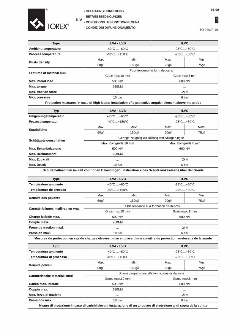
OPERATING CONDITIONS
BETRIEBSBEDINGUNGEN
CONDITIONS DE FONCTIONNEMENT
CONDIZIONI DI FUNZIONAMENTO
Tipo ILVA - ILVB ILVCTemperatura ambiente -40°C …+60°C -25°C…+60°C
Temperatura di processo -40°C…+150°C -25°C…+80°C
Densità polveriMax. Min. Max. Min.
60g/l 150g/l 20g/l 75g/l
Caratteristiche materiali sfusiScarsa propensione alla formazione di depositi
Grano max.10 mm Grano max.8 mm
Carico max. laterale 500 NM 600 NM
Coppia max. 250NM …
Max. forza di trazione … 2kN
Pressione max. 10 bar 6 bar
Misure di protezione in caso di carichi elevati: installazione di un angolare di protezione al di sopra della sonda
04
Type ILVA - ILVB ILVCAmbient temperature -40°C …+60°C -25°C…+60°C
Process temperature -40°C…+150°C -25°C…+80°C
Dusts densityMax. Min. Max. Min.
60g/l 150g/l 20g/l 75g/l
Features of material bulkPoor tendency to form deposits
Grain max.10 mm Grain max.8 mm
Max. lateral load 500 NM 600 NM
Max. torque 250NM …
Max. traction force … 2kN
Max. pressure 10 bar 6 bar
Protection measures in case of high loads: Installation of a protective angular element above the probe
Typ ILVA - ILVB ILVCUmgebungstemperatur -40°C …+60°C -25°C…+60°C
Prozesstemperatur -40°C…+150°C -25°C…+80°C
StaubdichteMax. Mind. Max. Mind.
60g/l 150g/l 20g/l 75g/l
SchüttguteigenschaftenGeringe Neigung zur Bildung von Ablagerungen
Max. Korngröße 10 mm Max. Korngröße 8 mm
Max. Seitenbelastung 500 NM 600 NM
Max. Drehmoment 250NM …
Max. Zugkraft … 2kN
Max. Druck 10 bar 6 bar
Schutzmaßnahmen im Fall von hohen Belastungen: Installation eines Schutzwinkeleisens über der Sonde
Type ILVA - ILVB ILVCTempérature ambiante -40°C …+60°C -25°C…+60°C
Température de process -40°C…+150°C -25°C…+80°C
Densité des poudresMax. Min. Max. Min.
60g/l 150g/l 20g/l 75g/l
Caractéristiques matières en vracFaible tendance à la formation de dépôts
Grain max.10 mm Grain max. 8 mm
Charge latérale max. 500 NM 600 NM
Couple maxi. 250NM …
Force de traction maxi. … 2kN
Pression maxi. 10 bar 6 bar
Mesures de protection en cas de charges élevées: mise en place d'une cornière de protection au-dessus de la sonde
-
-
-
-
05.09
1TO.920.T.
ILV
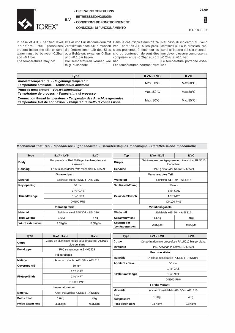
Nel caso di indicatori di livellocertificati ATEX le pressioni pre-senti all’interno del silo o contai-ner devono essere comprese tra-0.2bar e +0.1 bar.Le temperature potranno esse-re :
Mechanical features - Mechanisce Eigenschaften - Caractéristiques mécanique - Caratteristiche meccaniche
Type ILVA - ILVB ILVC
Corpo Corpo in alluminio pressofuso RAL5010 blu genziana
Involucro IP66 secondo la norma EN 60529
Pezzo avvitato
Materiale Acciaio inossidabile AISI 304 - AISI 316
Apertura chiave 50 mm
Filettatura/Flangia
1 ½" GAS
1 ½" NPT
DN100 PN6
Forche vibranti
Materiale Acciaio inossidabile AISI 304 - AISI 316
Pesocomplessivo 1.6Kg 4Kg
Peso estensioni 2.5Kg/m 0.5Kg/m
05
OPERATING CONDITIONS
BETRIEBSBEDINGUNGEN
CONDITIONS DE FONCTIONNEMENT
CONDIZIONI DI FUNZIONAMENTO
In case of ATEX certified levelindicators, the pressurespresent inside the silo or con-tainer must be between-0.2barand +0.1 bar.The temperatures may be:
Im Fall von Füllstandmeldern mitZertifikation nach ATEX müssendie Drücke innerhalb des Silosoder Behälters zwischen -0.2barund +0.1 bar liegen.Die Temperaturen können wiefolgt aussehen:
Dans le cas d’indicateurs de ni-veau certifiés ATEX les pres-sions présentes à l’intérieur dusilo ou conteneur doivent êtrecomprises entre -0.2bar et +0.1bar.Les températures pourront être:
Type ILVA - ILVB ILVCAmbient temperature - UmgebungstemperaturTempérature ambiante - Temperatura ambiente Max. 60°C Max.60°C
Process temperature - ProzesstemperaturTempérature de process - Temperatura di processo Max.150°C Max.80°C
Connection thread temperature - Temperatur des AnschlussgewindesTempérature filet de connexion - Temperatura filetto di connessione Max. 80°C Max.85°C
Type ILVA - ILVB ILVC
Body Body made of RAL5010 gentian blue die-castaluminium
Housing IP66 in accordance with standard EN 60529
Screwed part
Material Stainless steel AISI 304 - AISI 316
Key opening 50 mm
Thread/Flange
1 ½" GAS
1 ½" NPT
DN100 PN6
Vibrating forks
Material Stainless steel AISI 304 - AISI 316
Total weight 1.6Kg 4Kg
Wt. of extensions 2.5Kg/m 0.5Kg/m
Typ ILVA - ILVB ILVC
Körper Gehäuse aus druckgegossenem Aluminium RL 5010Enzianblau
Gehäuse IP66 gemäß der Norm EN 60529
Verschraubtes Teil
Werkstoff Edelstahl AISI 304 - AISI 316
Schlüsselöffnung 50 mm
Gewinde/Flansch
1 ½" GAS
1 ½" NPT
DN100 PN6
Vibrationsgabeln
Werkstoff Edelstahl AISI 304 - AISI 316
Gesamtgewicht 1.6Kg 4Kg
Gewicht derVerlängerungen 2.5Kg/m 0.5Kg/m
Type ILVA - ILVB ILVC
Corps Corps en aluminium moulé sous pression RAL5010bleu gentiane
Enveloppe IP66 suivant norme EN 60529
Pièce vissée
Matériau Acier inoxydable AISI 304 - AISI 316
Ouverture clé 50 mm
Filetage/Bride
1 ½" GAS
1 ½" NPT
DN100 PN6
Lames vibrantes
Matériau Acier inoxydable AISI 304 - AISI 316
Poids total 1.6Kg 4Kg
Poids extensions 2.5Kg/m 0.5Kg/m

1
05.09
ILV
TO.920.T.
-
-
-
-
Electrical features - Elektrische Eigenschaften
06
OPERATING CONDITIONS
BETRIEBSBEDINGUNGEN
CONDITIONS DE FONCTIONNEMENT
CONDIZIONI DI FUNZIONAMENTO
Type Relay output PNP Output
Power supply voltage 19…230V 50/60Hz +10% / 19…50V DC +10% 18…50V +10%
Maximum oscillation 7Vss DC 7Vss
Power absorbed Max. 18VA/ 2W Max. 0.6W (ILVA/ILVB)Max. 1.5W (ILVC)
Cable gland M20x1.5
Signal output
AC Max 250V,8A non inductiveDC Max. 30V, 5A non inductive (ILVA-ILVB) Permanent charge max. 0.4° protected against short-circuit
and overload. Voltage for protection against polarityinversion max. 55VAC max. 253V, 4A, 500VA Phi =1
DC Max. 253V, 4A 60W (ILVC)
Signal delayUncovered probe covered for approx. 1sec.
Covered probe uncovered for approx 1..2 sec.
Safety operation (FSL, FSH) Can be switched for minimum/maximum safety
Sensitivity Adjustable at two levels
Measuring frequency Approx. 200 Hz (ILVA-ILVB)Approx. 125 Hz (ILVC)
Insulation Power supply and output signal 2225 VRMS -
Protection Class I III
Typ Relaisausgang PNP Ausgang
Speisespannung 19…230V 50/60Hz +10% / 19…50V DC +10% 18…50V +10%
Max. Oszillation 7Vss DC 7Vss
Anschlusswert Max. 18VA/ 2W Max. 0.6W (ILVA/ILVB)Max. 1.5W (ILVC)
Kabelverschraubung: M20x1.5
Ausgangssignal
AC Max 250V,8A nicht induktivDC Max. 30V, 5A nicht induktiv (ILVA-ILVB) MAX. Dauerlast 0.4° bei Kurzschluss- und
Überlastungstest. Schutzspannung gegen Umkehr derPolarität max. 55VAC max. 253V, 4A, 500VA Phi =1
DC Max. 253V, 4A 60W (ILVC)
SignalverzögerungSonde frei bedeckti um 1sec.
Sonde bedeckt frei um 1..2 sec.
Sicherheitsbetrieb (FSL, FSH) umschaltbar auf kleinstes/größtes Sicherheitsniveau
Empfindlichkeit Auf zwei Stufen einstellbar
Messfrequenz Um 200 Hz (ILVA-ILVB)Um 125 Hz (ILVC)
Isolation Stromversorgung und Ausgangssignal 2225 VRMS -
Schutzart I III

-
-
-
-
05.09
1TO.920.T.
ILV
Tipo Uscita a relè Uscita PNP
Tensione di alimentazione 19…230V 50/60Hz +10% / 19…50V DC +10% 18…50V +10%
Oscillazione massima 7Vss DC 7Vss
Potenza assorbita Max. 18VA/ 2W Max. 0.6W (ILVA/ILVB)Max. 1.5W (ILVC)
Pressacavo M20x1.5
Uscita segnale
AC Max 250V,8A non induttivoDC Max. 30V, 5A non induttivo (ILVA-ILVB) Carico permanente max. 0.4° a prova di corto circuito e di
sovraccarico. Tensione di protezione contro l'inversione dipolarità max. 55VAC max. 253V, 4A, 500VA Phi =1
DC Max. 253V, 4A 60W (ILVC)
Ritardo segnaleSonda scoperta coperta circa 1sec.
Sonda coperta scoperta circa 1..2 sec.
Funzionamento di sicurezza (FSL, FSH) Commutabile per sicurezza minima/massima
Sensibilità Regolabile a due livelli
Frequenza di misura Circa 200 Hz (ILVA-ILVB)Circa 125 Hz (ILVC)
Isolamento Alimentazione e segnale di uscita 2225 VRMS -
Classe di protezione I III
07
OPERATING CONDITIONS
BETRIEBSBEDINGUNGEN
CONDITIONS DE FONCTIONNEMENT
CONDIZIONI DI FUNZIONAMENTO
Caractéristiques électrique - Caratteristiche elettriche
Type Sortie à relais Sortie PNP
Tension d'alimentation 19…230V 50/60Hz +10% / 19…50V DC +10% 18…50V +10%
Oscillation maximum 7Vss DC 7Vss
Puissance absorbée Max. 18VA/ 2W Max. 0.6W (ILVA/ILVB)Max. 1.5W (ILVC)
Presse-étoupe M20x1.5
Sortie signal
AC Max 250V,8A non inductifDC Max. 30V, 5A non inductif (ILVA-ILVB) Charge permanente max. 0.4° résistant à court-circuit et
surcharge. Tension de protection contre l'inversion depolarité max. 55VAC max. 253V, 4A, 500VA Phi =1
DC Max. 253V, 4A 60W (ILVC)
Retard signalSonde découverte couverte environ 1sec.
Sonde couverte Découverte environ 1..2 sec.
Fonctionnement de sécurité (FSL, FSH) Commutable pour sécurité minimum/maximum
Sensibilité Réglable à deux niveaux
Fréquence de mesure Environ 200 Hz (ILVA-ILVB)Environ 125 Hz (ILVC)
Isolement Alimentation et signal de sortie 2225 VRMS -
Classe de protection I III

1
05.09
ILV
TO.920.T.
-
-
-
-
ORDER CODES
BESTELLCODES
CODES DE SELECTION
CODICI DI SCELTA 08
0 = 0 mt1 = 1 mt2 = 2 mt3 = 3 mt4 = 4 mt5 = 5 mt
A = 10 mtB = 11 mtC = 12 mtD = 13 mtE = 14 mtF = 15 mt
0 = extension AISI 304 - 1 = extension AISI 316
1 = forks AISI 304 - 2 = forks AISI 316
3 = AISI 304 fitting - 4 = AISI 316 fitting
A = 1+1/2” conical connection - B = 1+1/2” NPT conical connectionL = DN100 PN6 flanged connection
E = Voltage 19..230 VAC - 19..50 VDC relé - D = Voltage 18..50 VDC PNP
1 = T max. 150°C (T. ambient 40°C) - 2 = T. max. 150°C (T. ambient 60°C)
0 = Standard - X = Certified ATEX II 1/2 D “dustEX”
A = standard level indicator - B =level indicator with extension (*)C =level indicator with extension cable (*) (T max 80° - T ambient 40°C)
ILV = indicateur de niveau à vibration
0011AE10AILV0 = 0 mt1 = 100 mm2 = 200 mm3 = 300 mm4 = 400 mm
5 = 500 mm6 = 600 mm7 = 700 mm8 = 800 mm9 = 900 mm
0
6 = 6 mt7 = 7 mt8 = 8 mt9 = 9 mt
G = 16 mtH = 17 mtI = 18 mtL = 19 mtM = 20 mt
0 = 0 mt1 = 1 mt2 = 2 mt3 = 3 mt4 = 4 mt5 = 5 mt
A = 10 mtB = 11 mtC = 12 mtD = 13 mtE = 14 mtF = 15 mt
0 = Verlängerung AISI 304 - 1 = Verlängerung AISI 316
1 = Gabeln Edelstahl 1.4301 - 2 = Gabeln Edelstahl 1.4401
3 = Anschluss Edelstahl 1.4301 - 4 = Anschluss Edelstahl 1.4401
A = Kegelanschluss 1+1/2” - B = Kegelanschluss 1+1/2” NPTL = Flanschanschluss DN100 PN6
E = Spannung 19..230 VAC - 19..50 VDC relé - D = Spannung 18..50 VDC PNP
1 = T max. 150°C (T. Umgebung 40°C) - 2 = T. max. 150°C (T. Umgebung 60°C)
0 = Standard - X = Zertifiziert nach ATEX II 1/2 D “dustEX”
ILV = SCHWINGUNGS-FÜLLSTANDMELDER
0011AE10AILV0 = 0 mt1 = 100 mm2 = 200 mm3 = 300 mm4 = 400 mm
5 = 500 mm6 = 600 mm7 = 700 mm8 = 800 mm9 = 900 mm
0
6 = 6 mt7 = 7 mt8 = 8 mt9 = 9 mt
G = 16 mtH = 17 mtI = 18 mtL = 19 mtM = 20 mt
* (ILVB min 300mm….max 4000mm Stufe da 100mm) - * (ILVC min 750mm… max 20000mm Stufe da 500mm)
* (ILVB min 300mm….max 4000mm in 100mm step) - * (ILVC min 750mm… max 20000mm in 500mm step)
A = Standard-Standanzeiger - B =Standanzeiger mit Verlängerung (*)C =Standanzeiger mit Verlängerungskabel (*) (T max 80° - T Umgebung 40°C)

1
05.09
ILV
TO.920.T.
-
-
-
-
DIMENSIONS
ABMESSUNGEN
DIMENSIONS
DIMENSIONI
1"1/2 GAS
25
Ø36
136Ø120
Ø120
125
M20x1.5
12517
0
Ø120
125
M20x1.5
175
170
1"1/2 GASØ36
136Ø120
125
25
136Ø120Ø120
125
M20x1.5
125L=
300-
4000
mm
1"1/2 GAS
Ø36
25
Ø120
125
M20x1.5
175
L=30
0...
4000
mm
1"1/2 GAS
Ø36
136Ø120
125
25
ILVA ILVA with extension - mit VerlängerungAvec rallonge d’extension - con estensione
Ambient temperature - UmgebungstemperaturTempérature ambiante - Temperatura ambiente
-40°C ÷ +40°CProcess temperature - Prozesstemperatur
Température de process - Temperatura processo-40°C ÷ +150°C
Ambient temperature - UmgebungstemperaturTempérature ambiante - Temperatura ambiente
-40°C ÷ +60°CProcess temperature - Prozesstemperatur
Température de process - Temperatura processo-40°C ÷ +150°C
ILVB ILVB con estensione - con estensionecon estensione - con estensione
Temperatura ambiente - UmgebungstemperaturTempérature ambiante - Temperatura ambiente
-40°C ÷ +40°CProcess temperature - Prozesstemperatur
Température de process - Temperatura processo-40°C ÷ +150°C
Ambient temperature - UmgebungstemperaturTempérature ambiante - Temperatura ambiente
-40°C ÷ +60°CProcess temperature - Prozesstemperatur
Température de process - Temperatura processo-40°C ÷ +150°C
10

-
-
-
-
05.09
1TO.920.T.
ILV
DIMENSIONS
ABMESSUNGEN
DIMENSIONS
DIMENSIONI
Ø8390
Ø83
120
L=75
0...2
0000
mm Ø42
155
Ø42
M20x1.5
1"1/2 GAS
195
170
ILVC
Ambient temperature - UmgebungstemperaturTempérature ambiante - Temperatura ambiente
-25°C ÷ +60°CProcess temperature - Prozesstemperatur
Température de process - Temperatura processo-25°C ÷ +80°C
11
Pneutrol International limited, 5 Caulside Drive, Antrim, Northern Ireland, BT41 2DU www.pneutrolspares.com, [email protected], Tel +44 (0) 28 9448 1800


![[ pagine 11 e 12 ] Ascolti, Auditel rinnova l’intero ...video.mondadori.com/mktpubbli/Daily/OldDaily/Today29giugno20168249.pdf · mo - eccomi - e birra Dreher si incontrano. Dreher](https://static.fdocuments.in/doc/165x107/5c67525c09d3f23a018b96ea/-pagine-11-e-12-ascolti-auditel-rinnova-lintero-video-mo-eccomi.jpg)