VHF/UHF TRANSCEIVER ID-51A ID-51E - icom.co.jp RADIOTELEPHONE SERVICE ... Opens the Advanced Manual...
108
This device complies with Part 15 of the FCC Rules. Operation is subject to the following two conditions: (1) this device may not cause harmful interference, and (2) this device must accept any interference received, including interference that may cause undesired operation. WARNING: MODIFICATION OF THIS DEVICE TO RECEIVE CEL- LULAR RADIOTELEPHONE SERVICE SIGNALS IS PROHIBITED UNDER FCC RULES AND FEDERAL LAW. BASIC MANUAL The photo shows the ID-51E version. ID-51A ID-51E VHF/UHF TRANSCEIVER
Transcript of VHF/UHF TRANSCEIVER ID-51A ID-51E - icom.co.jp RADIOTELEPHONE SERVICE ... Opens the Advanced Manual...

This device complies with Part 15 of the FCC Rules. Operation is subject to the following two conditions: (1) this device may not cause harmful interference, and (2) this device must accept any interference received, including interference that may cause undesired operation.
WARNING: MODIFICATION OF THIS DEVICE TO RECEIVE CEL-LULAR RADIOTELEPHONE SERVICE SIGNALS IS PROHIBITED UNDER FCC RULES AND FEDERAL LAW.
BASIC MANUAL
New2001
The photo shows the ID-51E version.
ID-51AID-51E
VHF/UHF TRANSCEIVER

i
New2001
FEATURES
❍ The dualwatch function simultaneously monitors VHF/VHF, UHF/UHF and VHF/UHF bands*.
Two band monitoring plus the Broadcast (BC) Radio.
* DV/DV, AM/AM, FM-N/FM-N and DV/FM-N mode dualwatch is not available.
❍ Rapid charging is possible, and the charg-ing time period is approximately 3 hours with the supplied battery pack. ❍ Built-in GPS receiver allows you to check your current position, or automatically send a reply with your position to the caller sta-tion. ❍ Voice recorder records your QSO conver-sation, voice audio for TX and microphone voice audio. ❍ The microSD card slot that can accept dif-ferent cards to backup settings, various memories, the GPS log and so on.
Icom, Icom Inc. and the Icom logo are registered trademarks of Icom Incorporated (Japan) in Japan, the United States, the United King-dom, Germany, France, Spain, Russia, Australia, New Zealand, and/or other countries.
Adobe, Acrobat, and Reader are either registered trademarks or trademarks of Adobe Systems Incorporated in the United States and/or other countries.Microsoft, Windows and Windows Vista are registered trademarks of Microsoft Corporation in the United States and/or other countries.
Thank you for choosing this Icom product. This product is de-signed and built with Icom’ s state of the art technology and craftsmanship. With proper care, this product should provide you with years of trouble-free operation.
This product combines traditional analog technologies with the new digital technology, Digital Smart Technologies for Amateur Radio (D-STAR), for a balanced package.
Icom is not responsible for the destruction, damage to, or performance of any Icom or non-Icom equipment, if the malfunction is because of:• Force majeure, including, but not limited to, fires,
earthquakes, storms, floods, lightning, other natural disasters, disturbances, riots, war, or radioactive contamination.
• The use of Icom transceivers with any equipment that is not manufactured or approved by Icom.
New2001
ii
EXPLICIT DEFINITIONSWORD DEFINITION
R DANGER!Personal death, serious injury or an ex-plosion may occur.
R WARNING!Personal injury, fire hazard or electric shock may occur.
CAUTION Equipment damage may occur.
NOTERecommended for optimum use. No risk of personal injury, fire or electric shock.
IMPORTANTREAD ALL INSTRUCTIONS carefully and completely before using the transceiver.
SAVE THIS INSTRUCTION MANUAL— This in-struction manual contains basic operating instructions for the ID-51A/ID-51E.
For Advanced features and instructions, open the Advanced manual that is on the supplied CD.
SUPPLIED ACCESSORIESThe following accessories are supplied with the transceiver.
Antenna Hand strap Battery charger(BC-167SA/SD/SV)*1
Belt clip Battery pack(BP-271)
CD*2
*1 Not supplied, or the shape is different, depending on the transceiver version.
*2 Includes the CS-51PLUS2 cloning software

iii
New2001
The following manuals and installers are included on the CD.See the PDF type Advanced manual or “About the DV Gate-way function” that can be downloaded from the Icom website for the functions that are not described on this manual.•Basic manual Instructions for the basic operations, the same as this man-
ual•Advanced manual Instructions for the advanced operations and more details
than are described in this manual•HAMradioTerms A glossary of HAM radio terms•CS-51PLUS2Instructionmanual Instructions for the CS-51PLUS2 cloning software installa-
tion and use•CS-51PLUS2Installer Installer for the CS-51PLUS2 cloning software•Adobe®Acrobat®Reader®Installer Installer for Adobe® Acrobat® Reader®
ABOUT THE SUPPLIED CD
q Insert the CD into the CD drive. • Double click “Menu.exe” on the CD. • Depending on the PC setting, the Menu screen shown
below may be automatically displayed. w Click the appropriate file button to open it.
• To close the Menu screen, click [Quit].
A PC with the following Operating System is required.• Microsoft® Windows® 10, Microsoft® Windows® 8.1, Micro-
soft® Windows® 7, or Microsoft® Windows Vista®.
To read the guide or instructions, Adobe® Acrobat® Reader® is required. If you have not installed it, please install the Adobe® Acrobat® Reader® on the CD or downloaded it from Adobe Systems Incorporated’s website.
D StartingtheCD
Quits the menu screen
Opens the Glossary
Opens the Basic Manual (English)
Installs the CS-51PLUS2
Opens the Advanced Manual
Opens the Basic manual(Multi-language)
Installs the Adobe® Acrobat® Reader®
Opens the CS-51PLUS2 Instructions

New2001
iv
D WhenusingtheGPSreceiver• GPS signals cannot pass through metal objects. When using
the ID-51A or ID-51E inside a vehicle, you may not receive GPS signals. We recommend you use it near a window.
• The Global Positioning System (GPS) is built and operated by the U.S. Department of Defense. The Department is re-sponsible for accuracy and maintenance of the system. Any changes by the Department may affect the accuracy and function of the GPS system.
• When the GPS receiver is activated, please do not cover the ID-51A or ID-51E with anything that will block the satel-lite signals.
• The GPS receiver may not work if used in the following loca-tions:
1. Tunnels or high-rise buildings 2. Underground parking lots 3. Under a bridge or viaduct 4. In remote forested areas 5. Under bad weather conditions (rainy or cloudy day)• The GPS receiver may not work if the transceiver operates
near the 440.205 MHz. This is due to signals made in the internal circuit and does not indicate a transceiver malfunc-tion.
D SpurioussignalsDepending on the combination of the operating band and mode, the Dualwatch or monitoring Two Ham bands plus the Broad-cast (BC) radio may generate certain spurious signals, or noise may be heard. These do not indicate a transceiver malfunction.
D AboutchargingwiththepowerONID-51A/E’s charging circuit can charge the supplied battery pack in approximately 3 hours. But with this rapid circuit, the battery pack cannot be charged with the power ON, by default. So, be sure to turn OFF the power before charging. When “Charging (Power ON)”* is set to ON in the MENU screen, the battery pack can be charged even if the power is ON. (Only when the battery pack is attached, and the optional CP-12L, CP-19R or OPC-254L external DC power cable is connected to [DC IN].) But this operation may generate certain spurious signals, and the S-meter may appear, or noise may be heard.*MENU > Function > Charging(PowerON) (Default: OFF)• The charging time period with the power ON may differ, depending
on the operating condition.• The external DC power supply voltage must be between 10 ~ 16 V,
and the current capacity must be more than 2.5 A to charge the bat-tery pack with the power ON.
• When you operate the transceiver while charging, and if you cannot receive signals correctly, set “Charging (Power ON)”* to OFF, and disconnect the external DC power cable from [DC IN].
• When the supply voltage exceeds 14 V, the built-in protection circuit activates to reduce the transmit output power to approximately 2.5 W.
IMPORTANT NOTES

v
New2001
PRECAUTIONSR DANGER! NEVER short the terminals of the battery pack. Shorting may occur if the terminals touch metal objects such as a key, so be careful when placing the battery packs (or the transceiver) in bags, and so on. Carry them so that shorting cannot occur with metal objects. Shorting may damage not only the battery pack, but also the transceiver.
R DANGER! NEVER use and charge Icom battery packs with non-Icom transceivers or non-Icom chargers. Only Icom battery packs are tested and approved for use with Icom transceivers or charged with Icom chargers. Using third-party or counterfeit battery packs or chargers may cause smoke, fire, or cause the battery to burst.
R DANGER! NEVER operate the transceiver near unshield-ed electrical blasting caps or in an explosive atmosphere. This could cause an explosion and death.
R WARNING RF EXPOSURE! This device emits Radio Frequency (RF) energy. Caution should be observed when operating this device. If you have any questions regard-ing RF exposure and safety standards, please refer to the Federal Communications Commission Office of Engineering and Technology’s report on Evaluating Compliance with FCC Guidelines for Human Radio Frequency Electromagnetic Fields (OET Bulletin 65).
R WARNING! NEVER hold the transceiver so that the an-tenna is very close to, or touching exposed parts of the body, especially the face or eyes, while transmitting. The transceiv-er will perform best if the microphone is 5 to 10 cm (2 to 4 inches) away from the lips and the transceiver is vertical.
R WARNING! NEVER operate or touch the transceiver with wet hands. This could cause an electric shock or damage the transceiver.
R WARNING! NEVER operate the transceiver with an ear-phone, headphones or other audio accessories at high vol-ume levels. If you experience a ringing in your ears, reduce the volume or discontinue use.
R WARNING! NEVER connect the transceiver to a power source of more than 16 V DC or use reverse polarity. This could cause a fire or damage the transceiver.
CAUTION: DO NOT operate the transceiver unless the flex-ible antenna, battery pack and jack cover are securely at-tached. Confirm that the antenna and battery pack are dry before attaching. Exposing the inside of the transceiver to dust or water can cause serious damage to the transceiver.After exposure to water, clean the battery contacts thoroughly with fresh water and dry them completely to remove any wa-ter or salt residue.

New2001
vi
CAUTION: DO NOT operate the transceiver while driving a vehicle. Safe driving requires your full attention—anything less may result in an accident.
DO NOT use harsh solvents such as Benzine or alcohol when cleaning, because they will damage the transceiver surfaces.
DO NOT push [PTT] when you do not actually intend to transmit.
DO NOT place or leave the transceiver in direct sunlight or in areas with temperatures below –20°C (–4˚F) or above +60°C (+140˚F).
BE CAREFUL! The transceiver will become hot when operat-ing it continuously for long periods of time.
BE CAREFUL! The transceiver meets IPX7* requirements for waterproof protection. However, once the transceiver has been dropped, waterproof protection cannot be guaranteed because of possible damage to the transceiver’s case or wa-terproof seal.* Only when the BP-271 or BP-272 (option), flexible antenna,
[MIC/SP] cap, [DATA/DC IN] cap and [micro SD] slot cap are attached.
Place the transceiver in a secure place to avoid inadvertent use by unauthorized persons.
When the BP-273 is connected to the transceiver, it meets IPX4 requirements for splash resistance.When it is connected, the transceiver corresponds to IPX4.Even when the transceiver power is OFF, a slight current still flows in the circuits. Remove the battery pack or batteries from the transceiver when not using it for a long time. Other-wise, the installed battery pack or batteries will become ex-hausted, and will need to be recharged or replaced.
PRECAUTIONS

vii
New2001
BATTERY CAUTIONS D Batterycaution
R DANGER! NEVER strike or otherwise impact the battery pack. Do not use the pack if it has been severely impacted or dropped, or if it has been subjected to heavy pressure. Battery damage may not be visible on the outside of the case. Even if the surface of the pack does not show cracks or any other damage, the cells inside the pack may rupture or catch fire.R DANGER! NEVER leave the battery pack in places with tem-peratures above +60˚C (+140˚F). High temperature buildup in the battery cells, such as could occur near fires or stoves, inside a sun-heated vehicle, or in direct sunlight for long periods of time may cause the battery cells to rupture or catch fire. Excessive temperatures may also degrade pack’s performance or shorten the battery cell’s life.R DANGER! NEVER expose the battery pack to rain, snow, sea-water, or any other liquids. Do not charge or use a wet battery pack. If the pack gets wet, be sure to wipe it dry before using.R DANGER! NEVER place battery packs near a fire. Fire or heat may cause them to rupture or explode. Dispose of used packs in accordance with local regulations.R DANGER! NEVER solder the battery cell’s terminals, and NEVER modify the battery pack. This may cause heat genera-tion, and the battery cells may burst, emit smoke or catch fire.R DANGER! NEVER use the battery pack with a transceiver for which it is not specified. NEVER use a pack with any other equip-ment, or for any purpose that is not specified in this instruction manual.
R DANGER! NEVER let fluid from inside the battery cells get in your eyes. If it does, blindness can result. Rinse your eyes with clean water, without rubbing them, and immediately go to a doctor.R WARNING! NEVER use the battery pack if it emits an abnor-mal odor, heats up, or is discolored or deformed. If any of these conditions occur, contact your Icom dealer or distributor.R WARNING! NEVER let fluid from inside the battery cells come in contact with your body. If it does, immediately wash with clean water.R WARNING! NEVER put the battery pack in a microwave oven, high-pressure container, or in an induction heating cooker. This could cause a fire, overheating, or cause the battery cells to rupture.CAUTION: DO NOT use the battery pack out of the specified temperature range –20˚C to +60˚C (–4˚F to +140˚F). Using the pack out of its specified temperature range will reduce it’s perfor-mance and the battery cell’s life.CAUTION: DO NOT leave the pack fully charged, completely discharged, or in an excessive temperature environment (above +50˚C, +122˚F) for an extended period of time. Otherwise a short-er battery pack life could occur. If the battery pack must be left unused for a long time, it must be detached from the transceiver after discharging. You may use the pack until the remaining ca-pacity is about half, then keep it safely in a cool dry place in the following temperature range:
–20˚C (–4˚F) to +50˚C (+122˚F) (within a month).–20˚C (–4˚F) to +35˚C (+95˚F) (within three months).–20˚C (–4˚F) to +20˚C (+68˚F) (within a year).

New2001
viii
BE SURE to replace the battery pack with a new one approxi-mately five years after manufacturing, even if it still holds a charge. The material inside the battery cells will become weak after a period of time, even with little use. The estimated number of times you can charge the pack is between 300 and 500. Even when the pack appears to be fully charged, the operating time of the transceiver may become short when:• Approximately five years have passed since the pack was man-
ufactured.• The pack has been repeatedly charged.
D ChargingcautionR DANGER! NEVER charge the battery pack in areas with ex-tremely high temperatures, such as near fires or stoves, inside a sun-heated vehicle, or in direct sunlight. In such environments, the safety/protection circuit in the pack will activate and stop the charging.R DANGER! NEVER charge the transceiver during a lightning storm. It may result in an electric shock, cause a fire or damage the transceiver. Always disconnect the power adapter before a storm.R WARNING! NEVER charge or leave the battery pack in the battery charger beyond the specified time for charging. If the pack is not completely charged by the specified time, stop charg-ing and remove it from the battery charger. Continuing to charge the pack beyond the specified time limit may cause a fire, over-heating, or the battery cells may rupture.
R WARNING! NEVER insert the transceiver (with the battery pack attached) into the charger if it is wet or soiled. This could corrode the battery charger terminals or damage the charger. The charger is not waterproof.CAUTION: DO NOT charge the battery pack outside of the specified temperature range: 0˚C to +40˚C (+32˚F to +104˚F). Icom recommends charging the pack at +25˚C (+77˚F). The pack may heat up or rupture if charged out of the specified tempera-ture range. Additionally, battery performance or battery life may be reduced.BE SURE to turn the transceiver power OFF while charging with the supplied or optional charger (BC-167S/BC-202). The battery pack cannot be charged with the charger when the transceiver’s power is ON.
D Chargingtime
BATTERY CAUTIONS
BC-167S(Supplied)
BC-202(Optional)
BP-271 (Supplied) Approx. 3 hours Approx. 2 hours
BP-272 (Optional) Approx. 4.5 hours Approx. 3.5 hours
Battery packCharger

ix
New2001
FEATURES ............................................................................ iEXPLICIT DEFINITIONS ...................................................... iiIMPORTANT ......................................................................... iiSUPPLIED ACCESSORIES ................................................. iiABOUT THE SUPPLIED CD ............................................... iiiIMPORTANT NOTES ........................................................... ivPRECAUTIONS .................................................................... vBATTERY CAUTIONS ........................................................ vii
UNIqUE FUNCTIONS ................................ xi–xiii1 QSO Recording function ............................................. xi2 Auto Position Reply function ....................................... xi3 Voice TX function ........................................................ xi4 Near FM Repeater search function ............................ xii5 DV Fast data mode .................................................... xii6 Add-on functions for D-PRS ....................................... xii7 Connecting an Android™ device .............................. xii8 DV Gateway function .................................................xiii
1 PANEL DESCRIPTION ............................... 1–9 ■ Front, top and side panels ..........................................1 ■ Function display ..........................................................6
2 STARTING INITIAL SETUP .................... 10–19 ■ Attaching the Battery pack ........................................10 ■ Charging the battery pack .........................................11 ■ Inserting the microSD card .......................................11 ■ Power ON ..................................................................12 ■ Setting audio volume ................................................12 ■ Setting Date/Time .....................................................12 ■ Enter your call sign into the transceiver ....................14 ■ Register your call sign at a gateway repeater ...........16 ■ Save setting data onto a microSD card (Recommend) ..18
3 MENU SCREEN ...................................... 20–32 ■ Menu item selection ..................................................19 ■ Menu items and their details .....................................21
4 BASIC OPERATION ............................... 32–41 ■ Receiving ..................................................................32 ■ Dualwatch operation .................................................32 ■ Selecting the operating band ....................................34 ■ Selecting a tuning step..............................................34 ■ Selecting the operating mode ...................................35 ■ Setting a frequency ...................................................35 ■ Setting the squelch level ...........................................36 ■ Monitor function ........................................................36 ■ Selecting the Mode and the DR function ..................37
TABLE OF CONTENTS

New2001
x
■ Key Lock function ......................................................38 ■ Transmitting ...............................................................39 ■ BC Radio operation ...................................................41
5 MEMORY CHANNEL OPERATION ........ 42–43 ■ Memory channel programming .................................42 ■ Selecting the Memory channel .................................43
6 D-STAR OPERATION ............................. 44–72 ■ Unique features of D-STAR .......................................44 ■ D-STAR Introduction .................................................45 ■ About the DR (D-STAR Repeater) function ...............45 ■ Ways to Communicate with the DR function .............46 ■ Making a Simplex call with the DR function ..............47 ■ Accessing repeaters .................................................48 ■ Using the RX history .................................................51 ■ Capturing a call sign .................................................55 ■ Making a Local area call ...........................................56 ■ Making a Gateway Repeater call ..............................58 ■ Calling an individual station ......................................59 ■ Troubleshooting .........................................................61 ■ Reflector operation ....................................................63 ■ Updating the repeater list ..........................................69
7 RECORDING A qSO ONTO A microSD CARD ........................ 73–77
■ About the microSD card ............................................73 ■ Recording a QSO audio ............................................74 ■ Playing recorded audio .............................................75 ■ Removing the microSD card .....................................76
8 GPS OPERATION ................................... 78–80 ■ GPS operation ..........................................................78 ■ Checking your GPS position .....................................78 ■ GPS Logger function.................................................80
9 RESETTING .................................................. 81 ■ Resetting ...................................................................81
10 INFORMATION ........................................... 82 COUNTRY CODE LIST ................................................82 FCC INFORMATION .....................................................82
INDEX ......................................................... 83–85
INDEX FOR MENU ITEMS ........................ 86–89
SPECIFICATIONS ...................................... 90–91
TABLE OF CONTENTS

New2001
xi
New2001
UNIqUE FUNCTIONS
1 QSORecordingfunction
2 AutoPositionReplyfunctionThis section introduces unique functions built into the ID-51A/E.• See the PDF type Advanced manual or “About the DV Gateway
function” that can be downloaded from the Icom website for more details.
NOTE: This function requires a microSD card.
Repeat Voice TX waiting screen
This is JA3YUA
JA3YUA
3 VoiceTXfunction
When you receive a call addressed to your own call sign, but are in a situation that makes it difficult to operate the trans-ceiver, this function automatically replies with your own call sign and transmits your position.• See the PDF type Advanced manual’s Section 9 for details.
You can record the MAIN band QSO audio.
You can record only the receive audio or both the transmit and receive audio.You can also store and view the QSO/RX log file.• The log file stores following contents: RX Frequency, Operating mode (DV is fixed), Call sign of the caller station, Note after the call sign, Call sign of the called station, Ac-cess repeater call sign of the caller station or the gateway repeater call sign of your local area repeater, Access repeater call sign of the called station, Message included in the received call (up to 20 characters).
• See page 73 or the PDF type Advanced manual’s Section 11 for details.
You can transmit recorded audio once or repeatedly, which is useful for D-STAR events.• See the PDF type Advanced manual’s Section 17 for details.
NOTE: This function requires a microSD card.
Destination(ID-51A/E)Yourstation
q A call addressed to your own call sign.
w Your position is auto-matically transmitted.
e After receiving, the screen shows your position.

New2001
xii
UNIQUE FUNCTIONS
4 NearFMRepeatersearchfunction
5 DVFastdatamode
6 Add-onfunctionsforD-PRS
7 ConnectinganAndroid™device
You can select FM repeaters us-ing the DR function.The function can find only FM re-peaters in your transceiver’s re-peater list.• See the PDF type Advanced manu-
al’s Section 6 for details.
When FM repeater is selected.
D-PRS enables the transceiver to receive the Object, Item or Weather data in addition to position data.With the D-PRS add-on functions, you can receive informa-tion such as an event, traffic, emergency or weather while making a voice call in the DV mode.• See the PDF type Advanced manual’s Section 10 for details.
UN
IQU
E F
UN
CT
ION
S
In addition to low-speed data communication, you can send high-speed data using the DV Fast data mode. The data speed of the DV Fast data mode is approximately 3480 bps, and is 3.5 times faster than the low-speed data communication mode (approximately 950 bps).• See the PDF type Advanced manual’s Section 9 for details.
You can connect a third party Android™ device through the optional OPC-2350LU data cable.
When you connect an Android™ device to the transceiver, you can use the extended D-STAR functions with the RS-MS1A*, such as remote control operation or sending mes-sages and/or pictures.* The RS-MS1A is a freeware Android™ application.• See the PDF type Advanced manual’s Section 18 for details.

New2001New2001
xiii
UNIQUE FUNCTIONS
New2001
8 DVGatewayfunction
NOTE: A Global IP connection is necessary for PC (Windows®) or Android® device.See “About the DV Gateway function” on the Icom WEB site, http://www.icom.co.jp/world/ for details.Enter ‘ID-51’ into the Search box in the site.Before you set up the access point, check any regulations or laws in your country.
TerminalmodeThe Terminal mode enables you to make a Gateway call through the internet by connecting the optional OPC-2350LU to a PC (Windows®) or Android® device.
Even if you cannot access a D-STAR repeater, you can make a Gateway call through the internet by connecting the optional OPC-2350LU data cable to a PC (Windows®) or Android® device.
Internet
D-STAR repeater
ID-51A/E
PC or Android® device
AccessPointmodeThe Access Point mode enables the D-STAR transceiver to make a Gateway call through an ID-51A/E by connecting the optional OPC-2350LU to a PC (Windows®) or Android® device.
D-STAR repeater
Internet
PC or Android® device
ID-51A/E
D-STAR transceiver

New2001
1
1PANEL DESCRIPTION
New2001
1
e PTT SWITCH [PTT] (p. 39) Hold down to transmit, release to receive. For ID-51E only Push briefly and release, then hold down to transmit a
1750 Hz tone burst.
rCD(RXCALLSIGNDISPLAY)/D-PAD(LEFT)KEY [CD]/D-pad()
➥ While in the DV mode, hold down for 1 second to open the received calls record. (p. 52)
➥ While in the DR screen, or with the Menu screen or Quick Menu screen open, push to select an upper tier menu.
tSQUELCHKEY[SQL] ➥ Hold down to temporarily open the squelch and monitor the operating frequency.
➥ While holding down this key, rotate [DIAL] to adjust the squelch level. (p. 36)
y POWERKEY[ ] Hold down for 1 second to turn the transceiver power ON
or OFF. (p. 12)
uMENU•LOCKKEY[MENU ]➥ Push to enter or exit the Menu screen. (p. 20)➥ Hold down for 1 second to toggle the Key Lock
function ON or OFF. (p. 38)
■ Front,topandsidepanels
qw
r
u
i
o
!0
e
t
y
!1!2!3
!4!5
!6
!7
!8!9
@0
@1
@2
Functiondisplay (p. 5)
Internalmicrophone
Speaker
q ANTENNA CONNECTOR Connect the antenna here. • The optional AD-92SMA adapter connects an antenna with a
BNC connector.
w TX/RX INDICATOR [TX/RX] (p. 39) Lights red while transmitting, lights green while receiving a
signal or when the squelch is open.
PAN
EL
DE
SC
RIP
TIO
N
qw
e
rt
y
u
SpeakerInternalmicrophone
Functiondisplay (p. 6)

2
1 PANEL DESCRIPTION
New2001
2
New2001
iMODE•SCANKEY[MODE•SCAN]➥ Push to select the operating mode. (p. 35) • Selectable operating modes are AM, FM, FM-N and
DV.➥ Hold down for 1 second to enter the scan type
selection mode. • Push again to start the scan. • Push to stop the scan.
oMAIN•DUALKEY[MAIN•DUAL]➥ Push to toggle the main band between A and B
bands. (p. 33)➥ Hold down for 1 second to toggle the Dualwatch
function ON or OFF. (p. 33)
!0microSDCARDSLOT[microSD] Insert a microSD card of up to 32 GB.
!1ENTERKEY[ENT] When the DR set screen, Menu screen or Quick Menu
screen is displayed, push to set the selected item or op-tion.
!2DR(D-STARREPEATER)/D-PAD(DOWN)KEY [DR]/D-pad()
➥ Hold down for 1 second to display the DR screen.
➥ While in the DR screen, or with the Menu screen or Quick Menu screen open, push to move the value or option selector bar down.
■ Front, top and side panels (Continued)
qw
r
u
i
o
!0
e
t
y
!1!2!3
!4!5
!6
!7
!8!9
@0
@1
@2
Functiondisplay (p. 5)
Internalmicrophone
Speaker
i
o!0!1
Speaker!2!3!4!5!6!7
Internalmicrophone
Functiondisplay (p. 6)

3
1PANEL DESCRIPTION
New2001
1
!3EXTERNALDCINJACK[DCIN] ➥ Connects to the supplied battery charger (BC-167SA/SD/SV), to charge the attached battery pack. (p. 11)
➥ Connect an external DC power source through the optional CP-12L or CP-19R cigarette lighter cable or OPC-254L DC power cable for external DC operation.
!4 DATAJACK[DATA] Connects to a PC through the optional data communica-
tion cable, for data communication in the DV mode, or for cloning. The jack is also used to connect an external GPS receiver.
!5QUICKMENU•SPEECHKEY[QUICKSPCH]➥ Push to enter or exit the Quick Menu screen.
(p. 5) • The Quick Menu is used to quickly select various
functions.➥ Hold down for 1 second to audibly announce
the displayed frequency, operating mode or call sign.
PAN
EL
DE
SC
RIP
TIO
N
!6MEMORY/CALL•SELECTMEMORYWRITEKEY [M/CALL•S.MW]
➥ In the VFO mode, push once to enter the Mem-ory selection mode, push again to enter the Call channel mode. (p. 37)
For ID-51A onlyIn the Call channel mode, push once to enter the Weather channel mode.
➥ Hold down for 1 second to enter the Select Memory Write mode. (p. 42)
!7VFO/MHz•CLEAR•OUTPUTPOWERKEY [VFO/MHz•CLR•LOW]
➥ Push to select the VFO mode. (p. 37)➥ While in the VFO mode, push to select
1 MHz or 10 MHz tuning steps. (p. 35)➥ With the Menu screen or Quick Menu screen
open, push to return to the operating mode be-fore displaying the Menu screen.
➥ While in the Memory Name or Call Sign Pro-gramming mode, push to delete a character. (p. 14)
➥ While scanning, push to cancel a scan. ➥ Hold down for 1 second to select the output
power. (p. 39)• Select the transmit output power of High, Mid, Low2,
Low1 or S-low.• While holding down this key, rotate [DIAL] to select
the desired output power.

4
1 PANEL DESCRIPTION
New2001 New2001
!8 CS(CALLSIGNSELECT)/D-PAD(RIGHT)KEY [CS]/D-pad()
➥ Hold down for 1 second to enter the operating call sign select mode.
➥ While in the DR screen, or with the Menu screen or Quick Menu screen open, push to select a lower tier menu.
!9 RXÚCS(RXCALLSIGNCAPTURE)/D-PAD(UP)KEY[RXÚCS]/D-pad()
➥ While in the DV mode, hold down for 1 second to display the RX History list.When “[RX>CS] Key” item is set to “Call Sign Capture,” the latest received call signs (station and repeaters) is set as the operating call signs after releasing this key. (p. 55)• While holding down this key, rotate [DIAL] to select
another call sign in RX History.When “[RX>CS] Key” item is set to “RX>CS List,” you can select a call sign (station and re-peaters) from the RX History list.
➥ While in the DR screen, or with the Menu screen or Quick Menu screen open, push to move the value or option selector bar up.
■ Front, top and side panels (Continued)
qw
r
u
i
o
!0
e
t
y
!1!2!3
!4!5
!6
!7
!8!9
@0
@1
@2
Functiondisplay (p. 5)
Internalmicrophone
Speaker Speaker
!8!9
@0
@1
@2
Internalmicrophone
Functiondisplay (p. 6)

New2001
5
1PANEL DESCRIPTION
1
@0 EXTERNALMICROPHONE/SPEAKERJACK [MIC/SP]
Connect a data cable, optional speaker microphone or headset.
See Section 18 in the Advanced manual for a list of avail-able options.
TIP: Be sure to turn OFF the power before connecting or disconnecting optional equipment to or from the [MIC/SP] jack.
@1 VOLUME CONTROL [VOL] Rotate to adjust the audio volume level. (p. 12)
@2 CONTROL DIAL [DIAL] ➥ Rotate to select the operating frequency. (p. 35) ➥ While in the Memory mode, rotate to select a memory channel. (p. 43)
➥ While scanning, rotate to change the scanning direc-tion.
➥ Hold down [SQL], and rotate to adjust the squelch level. (p. 36)
➥ While in the DR screen, or with the Menu screen or Quick Menu screen open, rotate to select a desired op-tion or value.
D quick MenuIn the Quick Menu, the selectable items differ, depending on the operating mode or function. The items shown below are examples.
VFOmode Memorymode CALL-CHmode DRfunction
Band Select Bank Select DUP Group Select
DUP DUP TONE Repeater Detail
TONE TONE TS DTMF TX
TS TS DTMF TX Voice TX
DTMF TX SKIP Voice TX GPS Information
Voice TX DTMF TX GPS Information GPS Position
GPS Information Voice TX GPS Position PRIO Watch
GPS Position GPS Information PRIO Watch Weather Alert
PRIO Watch GPS Position Weather Alert Display Type
Weather Alert PRIO Watch Display Type DSQL
Home CH Set Weather Alert Voltage Home CH Set
Voltage Home CH Set Band scope Voltage
Band scope Display Type <<REC Start>> Band scope
<<REC Start>> Voltage <<BC Radio ON>> <<REC Start>>
<<BC Radio ON>> Band scope <<BC Radio Mode>> <<BC Radio ON>>
<<BC Radio Mode>> <<REC Start>> <<GPS Logger only>> <<BC Radio Mode>>
<<GPS Logger only>> <<BC Radio ON>> <<GPS Logger only>>
<<BC Radio Mode>>
<<GPS Logger only>>
PAN
EL
DE
SC
RIP
TIO
N

6
1 PANEL DESCRIPTION
New2001 New2001
■ Functiondisplay
SinglebanddisplayBCRadiosettingwindow(Tuningmode)
Dualbanddisplay
q w r y uio !0
!1te q BATTERY ICON ➥ Shows the capacity of the attached battery pack.
Icon Batterystatus
The battery has sufficient capacity.
The battery is exhausted a little.
The battery is nearing exhaustion.
The battery is almost fully exhausted.
➥ “ ” appears when the optional battery case is attached.
w VOX ICON Appears when the optional headset is connected with the
OPC-2006LS plug adapter cable, and the VOX function is ON.
e OPERATING MODE ICONS (p. 35) Shows the selected operating mode. • DV, AM, FM and FM-N are selectable. • “DV-A” or “DV-G” appears when D-PRS (DV-A) or NMEA (DV-G)
transmission is selected in the DV mode. (p. 24)
rEMR/BK/PacketLoss/AutoReplyICON ➥ “EMR” appears when the Enhanced Monitor Request (EMR) mode is selected. (p. 26)
➥ “BK” appears when the Break-in (BK) mode is selected. (p. 26)
➥ “L” appears when Packet Loss has occurred. (p. 62) ➥ “ ” appears when the Automatic Reply function is se-lected. (p. 25)
!2

New2001
7
1PANEL DESCRIPTION
1
PAN
EL
DE
SC
RIP
TIO
N
t DUPLEX ICON “DUP+” appears when plus duplex is selected, and “DUP–
” appears when minus duplex is selected.
y BC RADIO ICON (p. 41) Appears when the BC radio is ON.
u GPS ICON ➥ Appears when the GPS function is ON. (pp. 13, 78)
Stays ON when the GPS receiver is activated and valid position data is received.
Blinks when invalid position data is being received. • The GPS icons can be turned OFF in the Menu screen.
(p. 13) ➥ “ S” blinks instead of the GPS icon, when the GPS
alarm beeps.
i RECORD ICON (p. 74) Appears while recording. • “ ” appears while recording. • “ ” appears while the recording is paused.
omicroSDICON ➥ “ ” appears when a microSD card is inserted. ➥ “ ” and “ ” alternately blink while accessing the microSD card.
!0AUTO POWER OFF ICON Appears when the Auto power OFF function is ON.
!1 TONE ICONS WhileoperatingintheFMorFM-Nmode:
• TONE: Enables the subaudible tone encoder.• TSQLS: Enables the tone squelch with the Pocket
Beep function.• TSQL: Enables the Tone Squelch function.• DTCSS: Enables the DTCS squelch with the Pocket
Beep function.• DTCS: Enables the DTCS Squelch function.• TSQL-R: Enables the Reverse Tone Squelch function.• DTCS-R: Enables the Reverse DTCS Squelch func-
tion.• DTCS (“DTCS” blinks): When you transmit, the selected DTCS code
is superimposed on your normal signal. When you receive, the function is OFF.• T-DTCS (“T” blinks): When you transmit, the selected subaudible
tone is superimposed on your normal signal. When you receive, the DTCS squelch opens
only for a signal that includes a matching DTCS code and polarity. (Audio is heard)
☞ Continued on the next page

8
1 PANEL DESCRIPTION
New2001 New2001
■ Function display
SinglebanddisplayBCRadiosettingwindow(Tuningmode)
Dualbanddisplay
!2
!3
!5!6
!7
!8!9
@0
!1
@1
@2
@3
!4
!1 TONE ICONS (Continued)• D-TSQL (“D” blinks): When you transmit, the selected DTCS code
is superimposed on your normal signal. When you receive, the tone squelch opens
only for a signal that includes a matching tone frequency. (Audio is heard)
• T-TSQL (“T” blinks): When you transmit, the selected subaudible
tone is superimposed on your normal signal. When you receive, the tone squelch opens
only for a signal that includes a matching tone frequency. (Audio is heard)
WhileoperatingintheDVmode:• DSQLS: Enables the Digital Call Sign squelch func-
tion with the Pocket Beep function.• DSQL: Enables the Digital Call Sign squelch func-
tion.• CSQLS: Enables the Digital Code squelch function
with the Pocket Beep function.• CSQL: Enables the Digital Code squelch function.
!2CLOCKDISPLAY Displays the current time.
!3 PRIORITY WATCH ICON Appears when Priority Watch function is ON.
!4 WEATHER ALERT ICON Appears when the Weather alert function is ON.

New2001
9
1PANEL DESCRIPTION
1
PAN
EL
DE
SC
RIP
TIO
N
!5 ATTENUATOR ICON Appears when the attenuator is ON in the AIR band mode.
!6SKIPICON ➥ “ SKIP” appears when the selected memory channel is
set as a Skip channel. ➥ “ PSKIP” appears when the displayed frequency is set
as a Skip frequency in the Memory mode. ➥ “ PSKIP” appears while the Frequency Skip Scan func-
tion is ON in the VFO mode.
!7 MEMORY CHANNEL NUMBER ➥ Displays the selected memory channel or bank num-ber. (p. 43)
➥ “C0” to “C3” appears when the Call channel is selected.
!8 MEMORY ICON (p. 43) Appears when the Memory mode is selected.
!9 S/RF METER ➥ Shows the relative signal strength of the receive signal. ➥ Shows the output power level of the transmit signal. (p. 39)
@0 POWER ICONS (p. 40) ➥ “ SLO” appears when S-low power is selected. ➥ “ LO1” appears when Low 1 power is selected. ➥ “ LO2” appears when Low 2 power is selected. ➥ “ MID” appears when Mid power is selected. ➥ No icon appears when High power is selected.
@1 MEMORY NAME DISPLAY While in the Memory mode, the programmed memory or
memory bank name is displayed.
@2 FREqUENCY READOUT Displays a variety of information, such as the operating
frequency, menu contents and so on. • The decimal point blinks during a scan.
@3 MAIN BAND ICON (p. 33) ➥ Shows the selected band (A or B) is the Main band. ➥ “ TM” appears while in the Terminal mode. ➥ “ AP” appears while in the Access Point mode.
TIP: See “About the DV Gateway function” that can be downloaded from the Icom website, for details.
New2001
10
New2001New2001
STARTING INITIAL SETUP2
Toattach Todetach
q
w qq
wBattery pack or battery case
Illustration shows the battery pack is attached.
■ AttachingtheBatterypack Attach or detach the battery pack or battery case, as illus-trated below.
Before starting D-STAR, the following steps are needed or recommended.
STEP 1 Attaching the Battery pack, and charging the bat-
tery. (p. 11)
STEP 2 Inserting a microSD card. (p. 11)
STEP 3 Turning ON the transceiver. (p. 12)
STEP 4 Adjust the audio level. (p. 12)
STEP 5 Receiving GPS data. (p. 13)
STEP 6 Entering your Call sign (MY) into the transceiver.
(p. 14)
STEP 7 Register your Call sign at a Gateway repeater.
(p. 16)
STEP 8 Save your initial setting onto the microSD card.
(p. 18)
You have completed the steps!! NOTE: Even when the transceiver power is OFF, a small current still flows in the transceiver. Remove the battery pack or case from the transceiver when not using it for a long time. Otherwise, the batteries in the pack or the case will become exhausted.When the temperature is around 0°C (+32°F) or below, the battery protection function automatically sets transceiver power to Low1 power (0.5 W), and disables power selections (High, Mid and Low2).

11
2STARTING INITIAL SETUP
New2001
2
New2001
q Make sure the transceiver is turned OFF. w Lift OFF the [micro SD] slot cover on the side panel. e With the terminals facing the front, insert the card into the slot until it locks in place, and makes a ‘click’ sound.
DO NOT touch the terminals.
Terminals facing the front
microSD card
[micro SD] slot
■ InsertingthemicroSDcard
Slot cover
NEVER forcibly or inversely insert the card. It will damage the card and/or the slot.
■ ChargingthebatterypackPrior to using the transceiver for the first time, the battery pack must be fully charged for optimum life and operation.• BE SURE to turn OFF the power while charging with the
supplied battery charger. Otherwise the attached battery pack cannot be charged.
• While charging, the charging icon “ ” sequentially shows eleven level steps along with the word “Charging...”.
• The icon disappears when the battery pack is completely charged.
•Chargingtime: BP-271 approximately 3.0 hours BP-272 approximately 4.5 hours
STA
RT
ING
INIT
IAL
SE
TU
P
r Completely close the [micro SD] slot cover.
NOTE: When removing, push in the microSD card until a click sounds. The card is unlocked, and you can pull it out.DO NOT remove the card from the transceiver while the card is being accessed. Otherwise, the card data may be corrupted or deleted. When removing the microSD card while the transceiver’s power is ON, see page 77 for details.
Transceiver
BE SURE to attach the battery pack before connecting the DC cable.
BP-271
to [DC IN]
BC-167S
to an AC outlet
The BC-167SA, BC-167SD and BC-167SV have different shapes.
BE SURE to turn OFF the power while charging.
12
2 STARTING INITIAL SETUP
New2001 New2001
■ PowerON ➥ Hold down [ ] for 1 second to turn ON power.
• After the opening message and power source voltage are dis-played, the operating frequency or repeater name appears.
• Hold down [ ] for 1 second to turn OFF power.
■ Settingaudiovolume ➥ Rotate [VOL] to adjust the audio level.
• If the squelch is closed, hold down [SQL] while setting the audio level.
• The display shows the volume level while adjusting.
■ SettingDate/TimeThe ID-51A/E has a built-in internal GPS receiver, and has a time correction function. The transceiver automatically sets the Date/Time settings to your local time.
D Localsetting
[ ]
[VOL]
q Push [MENU] . w Push D-pad() to select the root item “Time Set,” and then push D-pad(Ent).
• If the item is not displayed, push D-pad() one or more times to select the page.
D-pad
(�)
(Ent)
e Push D-pad() to select “UTC Offset,” and then push D-pad(Ent). r Push D-pad() to set to your local offset time.
(Example: –8:00) t Push [MENU] to exit the Menu screen.
TIP: The “GPS Time Correct” item in the Time Set menu is set to “Auto” as the default setting.(MENU > Time Set > GPSTimeCorrect) (p. 30)
TIP: The opening message and power source voltage dis-play options can be turned ON or OFF in the Display menu.(MENU > Display > OpeningMessage) (p. 29)(MENU > Display > Voltage(PowerON)) (p. 29)
TIP: The beep level is adjusted in the Sounds menu.(MENU > Sounds > Beep Level) (p. 30)

New2001
13
2STARTING INITIAL SETUP
2
D ReceivingGPSdata
Check whether or not the GPS receiver is receiving your position and time. The GPS icon blinks when searching for satellites. ➪ ➪ ➪
The GPS icon stops blinking when the minimum number of needed satellites are found.
• It may take only a few seconds to calculate your position. But depending on the environment, it may take a few minutes. If you have difficulties receiving, we recommend that you try a different location.
• When the “GPS Select” item is set to “Manual,” the icon does not appear. (Default: Internal GPS)
(GPS > GPS Set > GPS Select)
TIP: After the “ ” icon stops blinking, the transceiver au-tomatically sets the Date/Time setting to your local time.If the “ ” icon does not stop blinking, manually set the “Date/Time” setting.(MENU > Time Set > Date/Time) (p. 30)
ToprolongthebatterylifeintheGPSmodeTo prolong the battery life while in the GPS is ON, manually update your position with the received GPS data.
q Confirm the “ ” icon stops blinking. w Open the MANUAL POSITION screen, and then push [QUICK] .
( MENU > GPS > GPS Set> ManualPosition) e Push D-pad() to select “Capture From GPS,” and then push D-pad(Ent).
• Your current position is now memorized and displayed on the MANUAL POSITION screen.
r After updating, set the “GPS Select” option to “Manual.” ( MENU > GPS > GPS Set > GPS Select) (p. 23)
STA
RT
ING
INIT
IAL
SE
TU
P

14
2 STARTING INITIAL SETUP
New2001 New2001
■ Enteryourcallsignintothetransceiver
q Push [MENU] . • The MENU screen is displayed.
w Push D-pad() to select the root item “My Station,” and then push D-pad(Ent).
• If the item is not displayed, push D-pad() one or more times to select the page.
D-pad
(�)
(Ent)
e Push D-pad() to select “My Call Sign,” and then push D-pad(Ent).
• The MY CALL SIGN screen is displayed.
r Push D-pad() to select MY call sign memory channel “1” ([MY1]).
t Push [QUICK] , and then push D-pad() to select “Edit.” Then, push D-pad(Ent).
• Displays the call sign edit screen.
MENU screen
Go to step i
You can enter up to six MY call signs, in [MY1] through [MY6].
1. DisplaytheMYCallSigneditscreen
Example: Enter “JA3YUA” as your own call sign into the MY call sign memory [MY1].
Go to step t
2. Enterthecallsign
y Rotate [DIAL] to select the first digit. (Example: J)
• A to Z, 0 to 9, / and (Space) are selectable.
• Move cursor: Push D-pad(). • Delete: Push [CLR] . • Insert: Move cursor, then rotate
[DIAL]. • Rotate [DIAL] counterclockwise
to enter a space. u Push D-pad() to move the cursor to the second digit.
Edit mode
NOTE: Your MY CALL SIGN must match the call sign reg-istered on a gateway repeat-er. (p. 16)

New2001
15
2STARTING INITIAL SETUP
2
i Repeat steps y and u to enter your own call sign of up to 8 characters, including spaces.
( For example: First J, then A, then 3, then Y, then U, then A)
o Push D-pad(Ent) to set the call sign.
• See the right column if you en-ter a note.
!0 Push D-pad(Ent) again to save and return to the MY CALL SIGN screen.
• Two beeps sound.
!1 Push [MENU] to exit the MENU screen.
BeepsCompleted
[DIAL]
Selects/exits the MENU screen
Moves the cursor
Selects
Deletes
Shows theQUICK MENU
Keysusedforentry
TIP: You can enter a note of up to 4 characters, such as the model of the transceiver, name, area name, and so on, after your call sign.
q Push D-pad() until the cursor moves to the right of the “/”.
w Repeat steps y and u on the previous page to enter a desired 4 character note.
(Example: ID51)
STA
RT
ING
INIT
IAL
SE
TU
P

16
2 STARTING INITIAL SETUP
New2001 New2001
■ Registeryourcallsignatagatewayrepeater
Ifneeded,ask thegatewayrepeateradministrator forcallsignregistrationinstructions.
To use the Internet, you must register your call sign with a repeater that has a gateway, usually one near your home lo-cation.
Abouttheregistrationprocess:This section describes the call sign registration process at a repeater that is connected to the US Trust server. There are other systems as well, and they have their own registration process. For information on how to register on one of them, contact the administrator of a repeater that uses the alternate system.
1. Gotothecallsignregistrationscreen
q Go to the following URL to find the gateway repeater clos-est to you.
http://www.dstarusers.org/repeaters.php w Click the call sign of the repeater that you want to register to. e Click the “Gateway Registration URL:” link address. r The “D-STAR Gateway System” screen appears.
Click [Register] to start the New User registration.
Click

New2001
17
2STARTING INITIAL SETUP
2
2. Registeryourcallsign
t Follow the registration instructions on the registration screen. y When you receive a notification from the administrator, your call sign registration has been approved, but the whole process is not yet complete.
NOTE: It may take a few days for the administrator to ap-prove you.
3. Registeryourequipmentinformation
u After your registration is approved, log in your personal ac-count with your registered call sign and password.
Click
4. RegisteryourD-Starequipment
i Register your D-STAR equipment information. Ask the gateway repeater administrator for details.
o When your registration is complete, log out of your per-sonal account, and start using the D-STAR network.
NOTE: You must register your D-STAR equipment BEFORE you can make calls through the gateway.
STA
RT
ING
INIT
IAL
SE
TU
P

18
2 STARTING INITIAL SETUP
New2001 New2001
D FormattingthemicroSDcardTIP: • If you use a brand new microSD card, format the card, by
doing the following steps.• Formattingacarderasesallitsdata.Before formatting
any programmed card, make a backup file of its current data on your PC.
• When the microSD card is formatted in the transceiver, the formatting process creates an ID-51 folder on the card. The ICF file extracted from the downloaded Zip file must be copied into the setting folder that is inside the ID-51 folder, otherwise the transceiver will not see it.
q Push [MENU] . • The MENU screen is displayed.
w Push D-pad() to select the root item (“SD Card”), and then push D-pad(Ent).
D-pad
(�)
(Ent)
e Push D-pad() to select “Format,” and then push D-pad(Ent).
• The confirmation screen “Format OK?” appears. • If the item is not displayed, push D-pad() one or more times to
select the page. r Push D-pad() to select “YES,” and then push D-pad(Ent) to format.
• The formatting starts and the display shows the formatting prog-ress.
• NEVER turn OFF the power while formatting. t After formatting, the display automatically returns to the SD CARD menu.
Memory channels, item settings in the menu screen, and re-peater lists can be saved on the microSD card.Saving data settings on the microSD card allows you to easily restore the transceiver to its previous settings, even if an All Reset is performed.
■ SavesettingdataontoamicroSDcard(Recommended)

New2001
19
2STARTING INITIAL SETUP
2
STA
RT
ING
INIT
IAL
SE
TU
P
D SavesettingTIP: Data settings are saved in the “icf” file format that is used in the CS-51PLUS2 cloning software.The saved data on the microSD card can be copied onto a PC and edited with the cloning software.Data settings can be saved as a new file, or to overwrite an older file.
q Push [MENU] . w Push D-pad() to select the root item (“SD Card”), and then push D-pad(Ent).
D-pad
(�)
(Ent)
e Push D-pad() to select “Save Setting,” and then push D-pad(Ent).
r Push D-pad() to select “<<New File>>,” and then push D-pad(Ent).
• The FILE NAME screen is displayed. • The file name is automatically named in the following manner,
Setyyyymmdd_xx (yyyy: Year, mm: month, dd: day, xx: serial number)Example: If a 2nd file is saved on October 1, 2016, the file is
named “Set20161001_02”. • If you want to change the file name, see “Save with a different file
name” (Section 2 in the Advanced manual). t Push D-pad(Ent) to save the file name.
• The confirmation screen “Save file?” appears. y Push D-pad() to select “YES,” then push D-pad(Ent) to save.
• While saving, a progress bar is displayed, then the “SD CARD” screen is displayed after the save is completed.
u Push [MENU] to exit the MENU screen.

New2001
20
New2001New2001
MENU SCREEN3 ■ Menu item selection
The Menu screen is used to program infrequently changed values or function settings.In addition to this page, see pages 21 through 31 for details of each item.
NOTE: The Menu system is constructed in a tree structure. You may go to the next tree level, or go back a level, de-pending on the selected item.
D Entering the Menu screenExample: Set the Auto Power OFF function to “30 min.”
e Push D-pad() to select “30min.”
Appears
TIP: To return to the default set-ting, push [QUICK] in step e to display “Default,” and then push D-pad(Ent).
q Push [MENU] . w Push D-pad() to select “Auto Power OFF,” and then push D-pad(Ent).
D-pad
(�)
(Ent)
( Time Set > Auto Power OFF) •Iftheitemisnotdisplayed,push
D-pad() one or more times to select the page.
r Push [MENU] to save, and exit the Menu screen.

21
3MENU SCREEN
New2001
3
ME
NU
SC
RE
EN
New2001
DUP/TONE...
Settings to access repeaters.Offset FreqSets the frequency offset for duplex (repeater) operation.Repeater ToneSelects a tone frequency used to access the repeaters.TSQL FreqSelects a tone frequency for the Tone squelch or the pock-et beep function.Tone BurstTurns the Tone Burst function ON or OFF. This function is used to suppress the squelch tail noise heard from the transceiver’s speaker in the FM mode.DTCS CodeSelects a DTCS (both encoder/decoder) code for DTCS squelch or the pocket beep function.DTCS PolaritySelects the DTCS polarity for the DTCS squelch or the pocket beep function.Digital CodeSelects a digital code for the Digital Code squelch func-tion.
■ Menu items and their detailsThis topic describes the Menu items and their details.
Scan
Set scan options.Pause TimerSelects the scan pause time. When receiving signals, the scan pauses according to the scan pause timer.Resume TimerSelects the scan resume time from a pause after the re-ceived signal disappears.Temporary Skip TimerSelects the Temporary Skip Time. When the time is set, specified frequencies are skipped for this period during a scan.Program SkipTurns the Program Skip Scan function ON or OFF for a VFO mode scan.Bank LinkSelects banks to be scanned during a Bank Link Scan.Program LinkSets the link function for the program scan edge channels.See the Advanced Manual for details of the preset values.
Voice Memo
Set the TX/RX voice recording options.QSO RecorderSet QSO recorder options.
<<REC Start>>*Starts recording the received signal audio.Play Files*Plays or deletes the recorded audio.
* Be sure to insert a microSD card into the transceiver before select-ing these items.

22
3 MENU SCREEN
New2001 New2001
* Be sure to insert a microSD card into the transceiver before select-ing these items.
■ Menu items and their details Root item “Voice Memo” (Continued)
Voice TX
Set microphone voice recording options.Record*Starts recording the microphone audio.TX Set
Repeat TimeSets the repeat interval. The transceiver repeatedly transmits the recorded voice audio at this interval.TX MonitorThe TX Monitor function outputs the TX voice audio from the speaker during voice transmission.
<<Single TX>>*The transceiver transmits the recorded voice audio only one time.<<Repeat TX>>*The transceiver repeatedly transmits the recorded voice audio for a maximum of 10 minutes.
Recorder SetREC ModeSelects whether or not to record the TX audio.RX REC ConditionSelects whether or not the squelch status affects the RX voice audio recording.File SplitSelects whether or not to automatically create a new file if transmission and reception, or squelch status (open and close) is switched.PTT Auto RECTurns the PTT Automatic Recording function ON or OFF.
Player SetSkip TimeSets the Skip time to rewind or forward the recorded audio when you push the fast-rewind or fast-forward key during playback.
Voice RecorderSet Voice recorder options.
Record*Starts recording the microphone audio.Play Files*Plays or deletes the recorded audio.Recorder SetSets the microphone sensitivity to suit your needs.
Player SetSets the Skip time to rewind or forward the recorded au-dio when you push the fast-rewind or fast-forward key during playback.
DV Auto Reply*Records a voice audio to use for the Auto Reply function in the DV mode.

New2001
23
3MENU SCREEN
3
ME
NU
SC
RE
EN
BC Radio
Set the Broadcast (BC) Radio options.BC Radio MemoryShows the BC Radio memory contents.BC Radio Set
Auto MuteSets the timer to automatically mute the BC Radio audio when the transceiver transmits or receive on the A band or B band.FM AntennaSelects the desired antenna for FM.Power Save (BC Radio)Turns the Power Save (BC Radio) function ON (to save battery power) or OFF.
<<BC Radio ON>>/<<BC Radio OFF>>Turns the BC Radio ON or OFF.<<BC Radio Mode>>Selects the BC Radio Mode with the transceiver in the Sleep mode.
GPS
Set GPS options.GPS Set
GPS SelectSelects the GPS receiver that the transceiver receives its position data from.
Power Save (Internal GPS)Cancels the internal GPS receiver power save function.Manual PositionManually enter your current position.GPS IndicatorTurns the GPS indicator ON or OFF.GPS Out (To DATA jack)Turns the output of GPS information from the internal GPS receiver to the [DATA] jack ON or OFF.
GPS InformationDisplays the received GPS information.GPS PositionDisplays your position, RX station, GPS memory and Alarm positions.GPS MemoryShows the GPS memory contents.GPS AlarmSet GPS alarm options.
Alarm SelectSelect the target for the GPS alarm function.Alarm Area (Group)Enter the GPS alarm active range.Alarm Area (RX/Memory)Select the GPS alarm active range.
GPS Logger*GPS LoggerTurns the GPS logger function ON or OFF, to store your route as you move.Record IntervalSelects the GPS Logger function record interval.

24
3 MENU SCREEN
New2001 New2001
■ Menu items and their details Root item “GPS” (Continued)
DV Memory
Stores call signs or repeater information to use in the DV mode.
Your Call SignStores station call signs. Add or edit call signs.
RX History
Displays the received call history in the DV mode.RX01:Displays the calls your transceiver received.
Call Sign
Set and display the DV mode call signs. UR: CQCQCQ, R1: --------, R2: --------, MY: --------Displays the operating call signs.Sets the operating call signs according to the type of call you want to make.
Record SentenceSelects the GPS Logger function record sentences.<<GPS Logger Only>>Turns ON the GPS logger function with the transceiver in the Sleep mode.
GPS TX ModeSet the GPS TX mode.
OFFTurns OFF the GPS TX function.D-PRS (DV-A)Set D-PRS options.
Unproto AddressEnters an unproto address, or keep the default.SymbolSelects a object station’s symbol to transmit.SSIDSelects the APRS® call sign SSID. CommentEnters a comment to transmit.Time StampSelects a format to transmit the current UTC time as a time stamp.AltitudeTurns the altitude transmit option ON or OFF.Data ExtensionSelects whether or not to transmit the course/speed data, power/height/gain/directivity data.
NMEA (DV-G)Set NMEA options.
GPS SentenceTransmits position data in selected GPS sentences.GPS MessageEnter a GPS message to be transmitted.
GPS Auto TXSelects a time option for the GPS automatic transmission function.

New2001
25
3MENU SCREEN
3
* Be sure to insert a microSD card into the transceiver before select-ing these items.
ME
NU
SC
RE
EN
My Station
Sets and stores your call sign to use in the DV mode.My Call SignStores your call signs. Select or edit a call sign to use in the DV mode.TX MessageStores TX Messages.Select or edit TX Message to use in the DV mode.
DV Set
Sets values for the DV mode operations.Tone ControlSet the received audio tones.
RX BassSets the DV mode received audio bass filter level to Cut, Normal or Boost.RX TrebleSets the DV mode received audio treble filter level to Cut, Normal or Boost.
Repeater List*Stores repeater information. Add or edit repeater informa-tion.( See the Advanced Manual for details of the preloaded data.)
NOTE: The repeater list described in this manual may dif-fer from your preloaded list.
RX Bass BoostTurns the DV mode received audio Bass Boost function ON or OFFTX BassSets the DV mode transmit audio bass filter level to Cut, Normal or Boost.TX TrebleSets the DV mode transmit audio treble filter level to Cut, Normal or Boost.
Auto ReplySelects the Automatic Reply function.DV Data TXSelects manually or automatically to transmit data.DV Fast DataThe DV Fast data mode sends data through both the audio and data frames in the DV mode. The data speed of the DV Fast data mode (approximately 3480 bps) is 3.5 times faster than the low-speed data communication mode (ap-proximately 950 bps). In the DV Fast data mode, no audio can be sent.
Fast DataSelects whether or not to use DV Fast data mode for data communication in the DV mode.GPS Data SpeedSet the GPS data transmission speed in the DV Fast data mode. TX Delay (PTT)Set the TX delay time after releasing [PTT] when the “DV Data TX” is set to “PTT” and data is sent in the DV Fast data mode.

26
3 MENU SCREEN
New2001 New2001
■ Menu items and their details Root item “DV Set” (Continued)
SPEECH
Sets the Speech functions.RX Call Sign SPEECHSelects the RX call sign speech function option while ON, or turn it OFF.RX>CS SPEECHTurns the RX>CS Speech function ON or OFF.DIAL SPEECHTurns the Dial Speech function ON or OFF.MODE SPEECHTurns the Operating Mode Speech function ON or OFF.SPEECH LanguageSelects either English or Japanese as the desired speech language.AlphabetSelects the alphabet character announcement type.SPEECH SpeedSelects Slow or Fast speech speedSPEECH LevelSets the volume level for the voice synthesizer.
Digital MonitorSelects the DV mode RX monitoring when [SQL] is held down.Digital Repeater SetTurns the digital repeater setting function ON or OFF. This function is usable in any DV mode except when using the DR function.RX Call Sign WriteTurns the RX call sign automatic write function ON or OFF. This function is usable in any DV mode except the DR screen.RX Repeater WriteTurns the repeater call sign automatic write function ON or OFF. This function is usable in any DV mode except when using the DR function.DV Auto DetectTurns the DV mode automatic detect function ON or OFF.RX Record (RPT)The transceiver can record the data of up to 50 individual calls.[RX>CS] KeySelects the [RX>CS] key’s operation when held down.BKTurns the BK (Break-in) function ON or OFF. The BK func-tion allows you to break into a conversation between two stations with call sign squelch enabled.
EMRTurns the EMR (Enhanced Monitor Request) communica-tion mode ON or OFF.After turning OFF the transceiver, the EMR mode will be cancelled.EMR AF LevelSets the audio output level when an EMR mode signal is received.

New2001
27
3MENU SCREEN
3
ME
NU
SC
RE
ENQSO/RX Log
Sets the QSO/RX History Log options.QSO Log*Selects whether or not to make a communication log on the microSD card.RX History Log*Selects whether or not to make a DV mode's receive his-tory log on the microSD card.CSV FormatSet CSV format options.
Separator/DecimalSelects the separator and the decimal character for the CSV format.DateSelects the date format.
DTMF/T-CALL
Sets the DTMF Memory functions.DTMF MemoryShows a list of the DTMF memory channels. The DTMF memory can store up to 24-digit DTMF code.DTMF SpeedSelects the DTMF transfer speed.
Function
Sets various function’s options.Power SaveSelects the Power Save options to reduce current drain and conserve battery power.MonitorSelects the [SQL] monitor function method.Dial Speed-UPTurns the dial speed acceleration ON or OFF.Auto RepeaterTurns the Auto Repeater function ON or OFF.Remote MIC KeyThe function assignments for keys on the optional HM-75LS can be changed for simple remote control operation.
During RX/StandbySelects the key function to be used while receiving or in the standby mode.During TXSelects the key function to be used while transmitting.
Key LockSelects the key lock type when the Key Lock function is turned ON.PTT LockTurns the PTT Lock function ON or OFF.Busy LockoutTurns the Busy Lockout function ON or OFF.Time-Out TimerSelects the Time-Out Timer time options.
* Be sure to insert a microSD card into the transceiver before select-ing these items.

28
3 MENU SCREEN
New2001 New2001
Display
Sets the Display options.BacklightSelects the transceiver backlight option.Backlight TimerSelects the backlight ON time period.LCD DimmerSelects the LCD backlight brightness level.LCD ContrastSets the contrast level of the LCD.
■ Menu items and their details Root item “Function” (Continued)
Active BandAllows continuous frequency selection across all bands by rotating [DIAL].MIC Gain (Internal)Sets the internal microphone sensitivity to suit your prefer-ence.MIC Gain (External)Sets the external microphone sensitivity to suit your prefer-ence.Data SpeedSelects the data transmission speed for low-speed com-munication, or between the [DATA] jack and external mod-ules like a GPS receiver, and so on.VOX
VOXTurns the VOX function ON or OFF.VOX LevelSets the VOX gain level.VOX DelaySets the VOX Delay time.VOX Time-Out TimerSets the VOX Time-Out Timer to prevent an accidental prolonged transmission.Headset SelectSelects the headset type to be used for the VOX func-tion to limit the maximum audio output level to protect the headset speaker.
CI-VSet CI-V options.
CI-V (DATA Jack)Selects whether or not to use the [DATA] jack to control an external device.CI-V AddressSets the transceiver’s unique CI-V hexadecimal address code.CI-V Baud RateSets the CI-V code transfer speed.CI-V TransceiveTurns the CI-V Transceive function ON or OFF.
HeterodyneEffective to eliminate internal spurious that may occur in a rare combination of dual band frequencies.Charging (Power ON)When the external DC power cable is connected, this func-tion enables charging the battery even with the power ON.

New2001
29
3MENU SCREEN
3
ME
NU
SC
RE
EN
Busy LEDTurns the TX/RX indicator ON or OFF.RX Call SignSelects the call sign and message display option when re-ceiving a call.RX MessageSelects to display and scroll a received message when re-ceiving a call, or not.Reply Position DisplaySelects whether or not to display the caller's position data when the data is included in the Auto Reply signal.DV RX BacklightTurns the DV RX Backlight function ON or OFF.TX Call SignSelects whether or not to display My or Your call sign while transmitting.Scroll SpeedSelects the scrolling speed of the message, call sign, or other text.Opening MessageSelects whether or not to display the opening message at power ON.Voltage (Power ON)Selects whether or not to display the voltage of the battery or external DC power source at power ON.Display UnitSet Display units options.
Latitude/LongitudeSelects position format to display the position.
Altitude/DistanceSelects the units to display the distance and altitude.SpeedSelects the units to display the speed.TemperatureSelects the units to display the temperature.BarometricSelects the units to display the barometric pressure.RainfallSelects the units to display the rainfall.Wind SpeedSelects the units to display the wind speed.
Display LanguageSelects the display language in the DR screen or Menu mode. When “English” is selected in System Language, this setting will disappear.System LanguageSelects English or Japanese as the system language of the transceiver.
Sounds
Sets the Sound options.Volume SelectSelects to adjust the audio output level of all bands togeth-er, all separately, or just the BC Radio separately.BC Radio LevelSets the initial audio output level difference between the BC Radio and the A and B bands when “All” is set in “Vol-ume Select.”

30
3 MENU SCREEN
New2001 New2001
■ Menu items and their details Root item “Sound” (Continued)
SD Card*
Sets the SD card options.Load Setting
File selectionLoads the settings file to the transceiver.
Save Setting<<New File>>Saves the settings as a new file.File selectionSaves the settings in a selected file.
Time Set
Sets the Time options.Date/TimeSets the current date and time.GPS Time CorrectSets to automatically correct the time using a GPS signal.UTC OffsetEnters the time difference between UTC and the local time.Auto Power OFFTurns the Auto power OFF function ON or OFF.
Earphone ModeTurns the Earphone mode ON or OFF.Beep LevelSets the beep output level.Beep/Vol Level LinkSelects whether or not the beep output level can be ad-justed by the [VOL] control.Key-Touch BeepTurns the confirmation beep tones when key is pushed, ON or OFF.Home CH BeepTurns the Home CH Beep ON or OFF.Band Edge BeepTurns the Band edge beep ON or OFF.Scan Stop BeepTurns the scan stop beep ON or OFF.Standby BeepTurns the standby beep function in the DV mode ON or OFF.Sub Band MuteSelects to mute the SUB band audio signal while receiving on the MAIN band, and/or sound a beep when a signal disappears on the SUB band.Scope AF OutputSelects the audio output option during a sweep.
DV Gateway
Enters the Terminal mode or Access Point mode.<<Terminal Mode>>Enters the Terminal mode.<<Access Point Mode>>Enters the Access Point mode.
* Be sure to insert a microSD card into the transceiver before select-ing these items.

New2001
31
3MENU SCREEN
3
ME
NU
SC
RE
EN
Others
Sets other options.Information
VoltageShows the voltage of the external DC power source.VersionShows the transceiver’s firmware version number.
CloneClone ModeReads or writes the CS-51PLUS2 data from or to the PC.Clone Master ModeSends the memory or setting data to other ID-51A/E.The clone Master mode of the Transceiver to Transceiver.
ResetPartial ResetReturns all settings to their defaults, without clearing the memory contents, call sign memories or repeater lists.All ResetClears all programming and memories, and return all set-tings to their defaults.
Import/ExportImport or export the CSV format file.
ImportSelects to import the Your call sign, Repeater list, or GPS memory data in the CSV format file.ExportSelects to export the Your call sign, Repeater list, or GPS memory data in the CSV format file.CSV FormatSelects the separator and the decimal character for the CSV format.
Separator/DecimalSelects the separator and the decimal character for the CSV format.DateSelects the date format.
SD Card InfoDisplays the free space and remaining recording time of the card. FormatFormats the card.UnmountElectronically unmounts the card.

32
New2001New2001
BASIC OPERATION4
New2001
Frequency range on the A/B bands:
108.000 MHz to 174.000 MHz
380.000 MHz to 479.000 MHz
•Some frequency ranges are blocked for the USA and Australian versions by regulation.
■ Receiving q Select the Main band. (p. 33)
•AbandorBbandareselectable. w Select the operating band. (p. 34)
•Air,144MHzor430MHzbandsareselectable. e Select the operating mode. (p. 35)
•AM,FM,FM-NandDVmodesareselectable. r Set the operating frequency. (p. 35) t Set the Squelch level. (p. 36)
■ Dualwatch operationDualwatch operation simultaneously monitors two frequencies.The ID-51A/E has two independent receiver circuits, A band and B band.Depending on the operating band or mode, the SUB band audio signal is muted. In such case, “ ” appears.In the Dualwatch mode, the audio output may be interrupted when the frequency is switched while scanning, or by other factors.
❍ SUB band mute status
MAIN band SUB band
DV modeDV mode
FM-N mode
FM-N modeDV mode
FM-N mode
AIR band AIR band
Appears when the SUB band audio signal is muted.
MAIN band
SUB band
Example: MAIN band is FM-N mode. SUB band is DV mode.

New2001
33
4BASIC OPERATION
New2001
4
D Turning Dualwatch ON or OFF ➥ Hold down [DUAL] for 1 second to turn the Dualwatch operation ON or OFF.
•In the Dualwatch mode, the display shows the A band in the up-per half and the B band in the lower half.
Upper: A band
Lower: B band
D MAIN band selection ➥ Push [MAIN] to alternately select the upper band or lower band as the MAIN band.
•“MAIN”appearsontheMAINband. •Bandselection,operatingfrequencysetting using [DIAL], oper-
ating mode selection, Memory channel selection, memory write and band scope function can be made on the MAIN band.
MAIN band is the upper half
MAIN band is the lower half
A band is displayed B band is displayed
BA
SIC
OP
ER
ATIO
N
•WhenDualwatchoperationisOFF,thedisplayshowsonlytheMAIN band.

34
4 BASIC OPERATION
New2001 New2001
■ Selecting the operating bandThe transceiver can receive the AIR, 144 MHz or 430 MHz bands.
AIR band
144 MHz band430 MHz band
q Push [V/MHz] to select the VFO mode. w Push [QUICK] . e Push D-pad() to select “Band Select,” and then push D-pad(Ent).
D-pad
(�)
(Ent)
r Push D-pad() to select the desired frequency band.
•Selectable frequency bands differ, depending on the trans-ceiver version. See the specifi-cations for details. (p. 90)
t Push D-pad(Ent) to set and exit the Quick Menu screen.
■ Selecting the tuning stepRotating [DIAL] changes the frequency in the selected tuning step.The VFO scan uses this step when searching for signals.
The following tuning steps are selectable. (kHz)
5.0 6.25 8.33* 10.0 12.5 15.0 20.0
25.0 30.0 50.0 100.0 125.0 200.0
*Appears only when the AIR band is selected.
D Tuning step selection q Push [QUICK] . w Push D-pad() to select “TS,” and then push D-pad(Ent).
D-pad
(�)
(Ent)
e Push D-pad() to select the desired tuning step.
•You can set the tuning stepfor both the VFO and Memory modes.
r Push D-pad(Ent) to save the setting and exit the Quick Menu screen.
When 5.0 kHz tuning steps is selected.

New2001
35
4BASIC OPERATION
4
■ Setting a frequency q When the VFO mode is selected, push [V/MHz] to select the 1 MHz or 10 MHz Quick Tuning function step, or turn it OFF.
•Whenthe1MHzstepisselected,the1MHzdigitblinks. •Whenthe10MHzstepisselected,the10MHzdigitblinks.
w Rotate [DIAL] to select the desired frequency in 1 MHz or 10 MHz steps. e When 10 MHz steps are selected, push [V/MHz] to cancel the Quick Tuning function.
Blinks
When the frequency changes in 1 MHz steps.
When the frequency changes in 10 MHz steps.
Blinks
■ Selecting the operating modeOperating modes are determined by the modulation of the radio signals. The transceiver has a total of four operating modes, AM, FM, FM-N and DV.
➥ Push [MODE] one or more times to select the operat-ing mode.
•TheAMmodecanbeusedforonlytheAIRband(108.000MHz~ 136.995 MHz) and AM BC radio (0.520 MHz ~ 1.710 MHz). (p. 42)
•Whenthe“GPSTXMode”itemisset,“DV-A”or“DV-G”appearsinstead of “DV.” (p. 24)
FM mode is selected
FM-N mode is selected
DV mode is selected
AM mode is selected
BA
SIC
OP
ER
ATIO
N

36
4 BASIC OPERATION
New2001 New2001
■ Monitor functionThis function is used to listen to weak signals without dis-turbing the squelch setting, or having to open the squelch manually, even when mute functions such as tone squelch are in use.
➥ While holding down [SQL], the transceiver monitors the operating frequency.
•The1stsegmentoftheS-meterblinks.
The first segment blinks.
■ Setting the squelch level q While holding down [SQL], rotate [DIAL] one click to dis-play the current squelch level. w While holding down [SQL], rotate [DIAL] to select the squelch level.
•“LEVEL1” is loosesquelch(forweaksignals)and“LEVEL9” istight squelch (for strong signals).
•“AUTO” shows automatic level adjustment by a noise pulsecounting system.
•“OPEN”showsacontinuouslyopensetting.(Thisoptionisnotselectable in the DV mode.)
Automatic squelch Maximum level
NOTE: An independent squelch level can be set for the A band and B band.You can set the MAIN band’s squelch level.
TIP: The [SQL] key can be set to ‘sticky’ operation in the Function menu. (MENU > Function > Monitor) (p. 27)

New2001
37
4BASIC OPERATION
4
■ Selecting the Mode and the DR function
D VFO mode q Push [V/MHz] .
•Push[V/MHz] selects the 1 MHz or 10 MHz Quick Tuning function step, or turns it OFF.
w Rotate [DIAL] to set the operating frequency.
D Memory/Call channel/Weather channel* mode q In the VFO mode, push [M/CALL] to select the Mem-ory mode.
•“ ” and the selected Memory channel number appear. w Push [M/CALL] again to select the Call channel mode, and then push again to select the Weather channel mode.
•The Memory mode, Call channel mode or Weather channelmode* are alternately selected.
•In the Call channel mode, the selected Call channel number(“C0” to “C3”) appears.
•In theWeather channelmode*, the selectedweather channelnumber (“WX-01” to “WX-10”) appears.
e Rotate [DIAL] to select a desired channel.
*Appears in only the USA version transceivers.
• VFO modeThe VFO mode is used to set the desired frequency.
• Memory modeThe Memory mode is used to operate on Memory channels, which store programmed frequencies and other parameters.
• Call channel modeCall channels are used for quick recall of most-often used frequencies.
• Weather channel mode*Weather channels are used for monitoring weather channels from the NOAA (National Oceanographic and Atmospheric Administration) broadcasts.
VFO mode
Memory mode Call channel mode
Weather channel mode*
BA
SIC
OP
ER
ATIO
N

38
4 BASIC OPERATION
New2001 New2001
DR screen
■ Selecting the Mode and the DR function (Continued)
D Selecting the DR (D-STAR Repeater) functionThe DR (D-STAR Repeater) function is used for D-STAR repeater operation. With this function, you can easily select the programmed repeaters and Your call signs by rotating [DIAL].See page 45 for the DR function details.
➥ Hold down for 1 second. •Displays the DR screen.
■ Key Lock functionActivate to prevent accidental frequency changes and unnec-essary function access.
➥ Hold down [LOCK] for 1 second to turn ON the Key Lock function.
•WhentheKeyLockfunctionisactivatedandthelockedkeyor[DIAL] is pushed or rotated, “LOCK ON” appears.
•ToturnOFFthefunction,holddown[LOCK] for 1 second again.
•[ ], [LOCK] , [PTT], [SQL] and [VOL] can be used while the lock function is activated.
The function is ON The function is OFF
TIP: Either or both the squelch control and volume control can also be locked in the Function menu.(MENU > Function > Key Lock) (p. 27)
TIP: See section 6 of this manual or sections 7 through 9 in the Advanced manual for details of the D-STAR operation with the DR function.
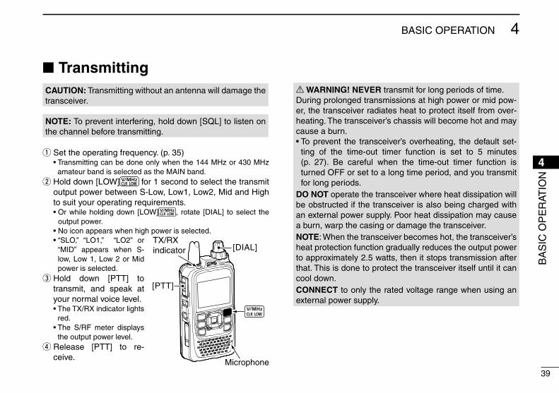
New2001
39
4BASIC OPERATION
4
■ TransmittingCAUTION: Transmitting without an antenna will damage the transceiver.
NOTE: To prevent interfering, hold down [SQL] to listen on the channel before transmitting.
q Set the operating frequency. (p. 35) •Transmittingcanbedoneonlywhenthe144MHzor430MHz
amateur band is selected as the MAIN band. w Hold down [LOW] for 1 second to select the transmit output power between S-Low, Low1, Low2, Mid and High to suit your operating requirements.
•Orwhileholdingdown [LOW] , rotate [DIAL] to select the output power.
•Noiconappearswhenhighpowerisselected. •“SLO,” “LO1,” “LO2” or
“MID” appears when S-low, Low 1, Low 2 or Mid power is selected.
e Hold down [PTT] to transmit, and speak at your normal voice level.
•TheTX/RXindicatorlightsred.
•The S/RF meter displaysthe output power level.
r Release [PTT] to re-ceive.
R WARNING! NEVER transmit for long periods of time.During prolonged transmissions at high power or mid pow-er, the transceiver radiates heat to protect itself from over-heating. The transceiver’s chassis will become hot and may cause a burn.•Toprevent the transceiver’soverheating, thedefaultset-
ting of the time-out timer function is set to 5 minutes (p. 27). Be careful when the time-out timer function is turned OFF or set to a long time period, and you transmit for long periods.
DO NOT operate the transceiver where heat dissipation will be obstructed if the transceiver is also being charged with an external power supply. Poor heat dissipation may cause a burn, warp the casing or damage the transceiver.NOTE: When the transceiver becomes hot, the transceiver’s heat protection function gradually reduces the output power to approximately 2.5 watts, then it stops transmission after that. This is done to protect the transceiver itself until it can cool down.CONNECT to only the rated voltage range when using an external power supply.
[DIAL]
[PTT]
TX/RXindicator
Microphone
BA
SIC
OP
ER
ATIO
N

40
4 BASIC OPERATION
New2001 New2001
D About transmit power levels❍ When the external DC power cable (13.5 V DC) is con-
nected, or a BP-271/BP-272 is used: 5 W (High)/2.5 W (Mid)/1.0 W (Low2)/
0.5 W (Low1)/0.1 W (S-Low) (approximately)
❍ When the BP-273 is used: Approximately 0.1 W (S-LOW) (fixed)
High power (5 W)
Mid power (2.5 W)
Low2 power (1.0 W)
S-Low power (0.1 W)
Low1 power (0.5 W)
• Transmit power level display
NOTE: When using the BP-273 battery case, “SLO,” “LO1,” “LO2,” “MID” or no icon (high power) appears on the display by holding down [LOW] for 1 second. But “SLO” appears while transmitting, and the output power is limited to approximately 0.1 watts.

New2001
41
4BASIC OPERATION
4
BA
SIC
OP
ER
ATIO
N
q Push [QUICK] . w Push D-pad() to select “<<BC Radio ON>>,” and then push D-pad(Ent).
D-pad
(�)
(Ent)
e The BC Radio pop up window appears, and exits the Quick Menu screen.
•“ ” appears.
Appears
■ BC Radio operation D Turning ON the BC Radio
➥ Push [MODE] to select the AM or FM radio mode.
D AM/FM radio mode selection
FM mode
AM mode
NOTE: This transceiver does not have a built-in bar antenna for AM broadcast band reception. If you have difficulties receiving depending on your environment, we recommend that you try a different location, or use an antenna which better suits the AM broadcast band.
TIP: To turn OFF the BC Radio, push [QUICK] , and then select “<<BC Ra-dio OFF>>.”

42
New2001New2001
MEMORY CHANNEL OPERATION5
New2001
■ Memory channel programming
q Push [V/MHz] to select the VFO mode. w Rotate [DIAL] to set a fre-quency to 146.030 MHz.
The Memory mode is useful to quickly select often-used re-peaters.This section describes the basic channel programming.See the Advanced Manual for details.Example: Programming 146.030 MHz into memory channel
11 (a blank channel).
r Rotate [DIAL] to select chan-nel 11.
•SelectCallchannels(C0toC3)to program into a call chan-nel, VFO to program into VFO or scan edge channels (0A/0B to 24A/24B) to program into a scan channel.
e Hold down [S.MW] for 1 second to enter the Select Memory write mode.
•1shortand1longbeepsound. •The memory channel number
blinks, and memory contents are displayed.
Hold down
for 1 sec.
t Hold down [S.MW] for 1 second to program, and then return to the VFO mode.
•3beepssound. •Before returning to the VFO
mode, the programmed mem-ory contents are briefly dis-played.
Hold down
for 1 sec.

New2001
43
5MEMORY CHANNEL OPERATION
New2001
5
ME
MO
RY
CH
AN
NE
L O
PE
RAT
ION
■ Selecting the Memory channelIn the memory mode, you can select the programmend mem-ory channels by rotating [DIAL].
q Push [M/CALL] one or more times to enter the Mem-ory mode.
•“ ” appears when the Mem-ory mode is selected.
•Push [M/CALL] again to select the Memory mode or Weather channel mode*. The Memory mode, Call chan-nel mode or Weather channel mode* are alternately selected.
* Appears only for the USA ver-sion transceivers.
Example: Selecting the Memory channel 7
w Rotate [DIAL] to select a de-sired memory channel.
•Memorychannels: “000” ~ “499”
•Scanedgechannels: “0A/0B” ~ “24A/24B”
•Only programmed memorychannels can be selected.
•Seepreviouspageformemoryprogramming details.
e Push [CLR] to exit the Memory mode.
Push .
Appears
Rotate [DIAL] to select channel 7.

44
New2001New2001
D-STAR OPERATION6
New2001
■ Unique features of D-STAR
● Easy Cross band operation through the repeater
● Easy call sign entry with the Repeater list or TX/RX History
● Call Sign Capture key [RX>CS] makes call sign capture easy.
1200 MHzID-51A/E(144/430 MHz)
You can communicate with a 1200 MHz D-STAR station using the ID-51A/E!
Easy Desti-nation (To) setting!
This key makes call sign capture easy!

New2001
45
6D-STAR OPERATION
New2001
6
■ D-STAR Introduction• The D-STAR repeater enables you to call a HAM station
near you, or around the world.• You can transmit and receive digital voice, including low-speed data, at the same time. You can transmit and receive position data from the built-in GPS receiver.
You can easily use D-STAR repeaters with the DR (D-STAR Repeater) function. With this function, you can select the pro-grammed repeater or frequency in “FROM” (the access re-peater or simplex), and Your call sign in “TO” (destination), as shown to the right.
IMPORTANT!
Before starting D-STAR, the following steps are needed.
STEP 1 Entering your call sign (MY) into the transceiver.
STEP 2 Registering your call sign (MY) to a gateway repeater.
STEP 3 Entering your D-STAR equipment into your registration form.
You have completed the steps!!
See pages 14 to 17 for details.
■ About the DR (D-STAR Repeater) function
Destination(Repeater/Station)
Access repeateror Simplex
In the DR screen
D-S
TAR
OP
ER
ATIO
N
NOTE: If the repeater set in “FROM” (Access Repeater) has no Gateway call sign, you cannot make a gateway call.

46
6 D-STAR OPERATION
New2001 New2001
■ Ways to Communicate with the DR functionWith the DR function, the transceiver has three ways to communicate, as shown below.
NOTE:• Using the repeater list is required to use the DR
function. (p. 69)• Before operating in the duplex mode, be sure to
check whether the repeater is busy, or not. If the repeater is busy, wait until it is clear, or ask for a “break” using a method acceptable to your local procedures.
• The transceiver has a Time-Out Timer function for DV operation. The timer limits a continuous trans-mission. Warning beeps will sound approximately 30 seconds before time-out and then again im-mediately before time-out.
INTERNET
Local area call Access repeater
Hamachorepeater
Hamacho area
INTERNET
Gateway call Hiranorepeater
Sappororepeater
Hirano area Sapporo area
To call through your local area (access) repeater.
To call through your local area (access) repeater, repeater gateway and the internet to your destination repeater or individual station’s last used repeater, using call sign routing.
Simplex call
To call another station not using a repeater.

New2001
47
6D-STAR OPERATION
6
You can make a transceiver to transceiver call (through no repeater) in the DR screen.
q Hold down for 1 sec-ond. w Push D-pad() to select “FROM,” and then push D-pad(Ent).
D-pad
(�)
(Ent)
e Push D-pad() to select “Re-peater List,” and then push D-pad(Ent).
Go to step e
Example: Making a simplex call on 433.450 MHz.
1. “FROM” (Simplex channel) setting
r Push D-pad() to select “20: Simplex,” and then push D-pad(Ent).
t Push D-pad() to select “433.450,” and then push D-pad(Ent).
• “433.450” is displayed in “FROM.”
• “CQCQCQ” is displayed in “TO.” - If a station call sign is set in
“TO”, select “Local CQ” in the TO SELECT screen to set “TO” to “CQCQCQ.”
D-S
TAR
OP
ER
ATIO
N
NOTE: Depending on the transceiver's version, the frequen-cies may be different. Check for acceptable frequencies for your operating area.
TIP: What is a Simplex Call?A simplex call is a direct call to another station, not using a repeater.
■ Making a Simplex call with the DR function

48
6 D-STAR OPERATION
New2001 New2001
q While holding down [PTT], speak at your normal voice level.
• The TX/RX indicator lights red. • The S/RF meter shows the
transmit output power level. w Release [PTT] to receive.
Transmitting
When you make a simplex call in the VFO mode, the LCD changes, as shown to the right.
NOTE: The simplex frequencies can be changed in the MENU screen. See the PDF type Advanced Manual section 9 for more details.(MENU > DV memory > Repeater List)
2. Hold down [PTT] to transmit
■ Accessing repeatersThis section describes how to check whether or not you can access your local area repeater (Access repeater), and if your signal is successfully sent to a destination repeater.
1. Select your Access repeater (“FROM”)
q Hold down for 1 sec-ond.
• The repeater list, described in this manual, may differ from your transceiver’s preloaded list.
DR screen
w Push D-pad() to select “FROM” (Access repeater), and then push D-pad(Ent).
D-pad
(�)
(Ent)
“FROM” is selected.
Go to step e
■ Making a Simplex call with the DR function (Continued)
TIP: If your call sign (MY) has not been set, or your call sign and equipment have not been registered at a D-STAR repeater, see pages 14 to 17.

New2001
49
6D-STAR OPERATION
6
e Push D-pad() to select “Re-peater List,” and then push D-pad(Ent).
Go to step y
TIP: • You have four other ways to select your access repeat-er, other than selecting it from repeater list. See the Ad-vanced Manual for more details.- Rotating [DIAL]- Searching for the nearest repeaters- Selecting from the TX History- Searching for a repeater using the DR scan
• When you select just the repeater name, the repeater call sign, its frequency, duplex setting, frequency offset and Gateway call sign are automatically set.
• The repeater list, described in this manual, may differ from your transceiver’s programmed list.
r Push D-pad() to select the repeater group where your access repeater is listed, and then push D-pad(Ent).
• Example: “11: Japan”
t Push D-pad() to select your access repeater, and then push D-pad(Ent).
• Example: “Hirano”
Repeater area Repeater call sign
y If the selected repeater name is displayed in “FROM” on the DR screen, the access re-peater setting is completed.
Completed
Completed
NOTE: See page 61 for status indications after a repeater system reply is received.
D-S
TAR
OP
ER
ATIO
N

50
6 D-STAR OPERATION
New2001 New2001
2. Select the Destination repeater (“TO”)
q Push D-pad() to select “TO” (Destination repeater), and then push D-pad(Ent).
D-pad
(�)
(Ent)
w Push D-pad() to select se-lect “Gateway CQ,” and then push D-pad(Ent).
“TO” is selected.
Go to step e
Example: Your destination repeater is Hamacho/Japan in the repeater list.
e Push D-pad() to select the repeater group where your destination repeater is listed, and then push D-pad(Ent).
• Example: “11: Japan”
r Push D-pad() to select your destination repeater, and then push D-pad(Ent).
• Example: “Hamacho”
t If the selected repeater name in step r is displayed in “TO” on the DR screen, the des-tination repeater setting is completed.
Completed
■ Accessing repeaters (Continued)

New2001
51
6D-STAR OPERATION
6
3. Check whether you can access the repeater
q Hold down [PTT] for approxi-mately 1 second to access the repeater.
Transmitting
w If you get a reply call, or “UR?” appears on the LCD within 3 seconds, your signal reached your access repeater and your call was successfully sent from your destination repeater.
Successfully sent!
NOTE: See page 61 for status indications after a reply is received.
■ Using the RX historyWhen a DV call is received, the call signs of the caller, the called station and the called station’s access repeater are stored in the RX history file.Up to 50 calls can be stored.
This section describes how to view the RX history screen and how to save the call sign to memory.
The S-meter appears and the caller’s call sign is displayed.
When receiving a call from “JM1ZLK.”
D-S
TAR
OP
ER
ATIO
N
☞ Continued on the next page

52
6 D-STAR OPERATION
New2001
New2001
■ Using the RX history (Continued)
1. To display a received call sign
q Hold down for 1 second. • Displays the RX HISTORY screen.
D-pad
(�)
(Ent)
w Push D-pad() to view other RX history.
NOTE: If you push D-pad(Ent) in the RX HISTORY screen, you can check the detailed contents of the RX history.
RX HISTORY record number
RX message
RX HISTORY screen(RX01)
Received date and time
Caller station(upper)** A note may be displayed after “/”.
Called station(lower)Repeater call sign
of the called station
RX HISTORY screen(RX02)
2. Save the destination call sign into your call sign mem-ory from RX History
q Push D-pad() to select the RX HISTORY record with the call sign that you want to save to memory.
w Push D-pad(Ent), and then push [QUICK] .
Call sign to be saved
e Push D-pad() to select “To Your Memory,” and then push D-pad(Ent).
D-pad
(�)
(Ent)
Go to step r

New2001
53
6D-STAR OPERATION
6
r Push D-pad() to select the call sign that you want to save, and then push D-pad(Ent).
• Example: “JM1ZLK”
TIP: The display changes to the YOUR CALL SIGN EDIT screen, and then the call sign is automatically saved.
t Push D-pad() to select “NAME,” and then push D-pad(Ent).
• A cursor appears and blinks.
y Rotate [DIAL] to select a desired character to enter a name of up to 16 characters, including spaces.
Go to step u
D-S
TAR
OP
ER
ATIO
N
About text entry• Push D-pad() to move the
cursor backward or forward.• While selecting a character,
push [QUICK] to change the character to an upper case or lower case letter.
• While selecting a digit, push [QUICK] to open the input mode selection window.
- Push D-pad() to select the desired Upper case let-ters, Lower case letters, Numbers or Symbols.
- To enter symbols, select “!”#,” and then push D-pad(Ent) to open the symbol character selection window. And ro-tate [DIAL] to select the desired symbol character, and then push D-pad(Ent).
• A space can be selected, in any input mode selected.• Move the cursor, then rotate [DIAL] to insert a character.• Rotate [DIAL] counterclockwise to enter a space.• If you make a mistake, push [CLR] to delete the se-
lected character, symbol or number, or hold down [CLR] to continuously erase the characters, first to the right, and then to the left of the cursor.
Input mode selection window
☞ Continued on the next page

54
6 D-STAR OPERATION
New2001 New2001
■ Using the RX history (Continued)
o Push D-pad() to select “YES,” and then push D-pad(Ent).
TIP: The saved call sign is dis-played on the YOUR CALL SIGN screen as a selectable destination.
Completed
“TOM” is added
Shows TOM’s call sign
u After entering the name, push D-pad(Ent).
• Example: “TOM”
i Push D-pad() to select “<<Add Write>>,” and then push D-pad(Ent).

New2001
55
6D-STAR OPERATION
6
■ Capturing a call signAfter you receive a repeater’s signal, the calling station’s call sign can be captured by touching the Call Sign Capture key ( ) for 1 second. After releasing, you can quickly and eas-ily reply to the call.
TIP: What is the Call Sign Capture key?Touching the Call Sign Capture key for 1 second sets the last received station’s call sign as a temporary destination, and makes replying quick and easy.
1. Set the received call sign to the destination
The Call Sign Capture key is here!
While receiving
When receiving a call from “JG3LUK.”
Hold down for 1 second.• After releasing, beeps sound, and
the station call sign is announced.
Blinks after select-ing a call sign.
NOTE:• If you want to select another call sign in the RX history,
rotate [DIAL] while holding down .• When the “[RX>CS] Key” item is set to “RX>CS List,” the
call sign is not set to the destination even after releasing the key. To set to the destination, select the call sign from the displayed list, and then push D-pad(Ent).
Beeps While holding down .
Beeps
After releasing .JG3LUK
D-S
TAR
OP
ER
ATIO
N
☞ Continued on the next page
TIP: To capture the calling station’s call sign after releasing the key, set the “[RX>CS] Key” item to “Call Sign Capture.”(MENU > DV Set > [RX>CS] Key) (p. 26)

56
6 D-STAR OPERATION
New2001 New2001
2. Hold down [PTT] to transmit
q While holding down [PTT], speak at your normal voice level.
Transmitting
w Push or [CLR] to return to the previous call sign setting.
Return to the previous screen
■ Making a Local area callA Local area call can be made when “Local CQ” is used to set “CQCQCQ” in “TO” (Destination).
1. Set “FROM” (Access repeater)
q Push D-pad() to select “FROM,” and then push D-pad(Ent).
w Push D-pad() to select “Repeater List,” and then push D-pad(Ent).
D-pad
(�)
(Ent)
e Push D-pad() to select the repeater group where your access repeater is listed, and then push D-pad(Ent).
• Example: “11: Japan”
Go to step r
■ Capturing a call sign (Continued)
TIP: What is a Local Area Call?To call through your local area (access) repeater.
NOTE: When a received signal is weak, DR scanning or the power save is ON, the call sign may not be received cor-rectly. In that case, “--------” appears, an error beep sounds, and a quick reply call cannot be made.

New2001
57
6D-STAR OPERATION
6
r Push D-pad() to select your access repeater, and then push D-pad(Ent).
• Example: “Hirano”
2. Set “TO” (Destination)
3. Hold down [PTT] to transmit
q Push D-pad() to select “TO,” and then push D-pad(Ent).
w Push D-pad() to select “Local CQ,” and then push D-pad(Ent).
• “CQCQCQ” is set in “TO.”
D-pad
(�)
(Ent)
TIP: The Local CQ call is used to call anyone, but you can call a specific station by simply saying their call sign.
While holding down [PTT], speak at your normal voice level.
Transmitting
D-S
TAR
OP
ER
ATIO
N

58
6 D-STAR OPERATION
New2001 New2001
■ Making a Gateway Repeater callA Gateway call can be made when a destination repeater is selected in “TO” (Destination).
q Push D-pad() to select “FROM,” and then push D-pad(Ent).
w Push D-pad() to select “Re-peater List,” and then push D-pad(Ent).
D-pad
(�)
(Ent)
e Push D-pad() to select the repeater group where your access repeater is listed, and then push D-pad(Ent).
• Example: “11: Japan”
r Push D-pad() to select your access repeater, and then push D-pad(Ent).
• Example: “Hirano430”
1. Set “FROM” (Access repeater)
Go to step r
Go to step e
2. Set “TO” (Destination)
q Push D-pad() to select “TO,” and then push D-pad(Ent).
w Push D-pad() to select “Gateway CQ,” and then push D-pad(Ent).
TIP: What is a Gateway Repeater Call?To call through your local area (access) repeater, repeater gateway, and the Internet to your desired destination re-peater.

59
6D-STAR OPERATION
New2001
6
e Push D-pad() to select the repeater group where your destination repeater is listed, and then push D-pad(Ent).
• Example: “11: Japan”
r Push D-pad() to select the destination repeater, and then push D-pad(Ent).
• Example: “Hamacho430”
3. Hold down [PTT] to transmit
While holding down [PTT], speak at your normal voice level.• “/” is automatically inserted to show
it is a repeater call sign.
Transmitting
TIP: The Gateway CQ call is used to call any repeater, but you can call a specific station by simply saying their call sign.
■ Calling an individual stationYou can make a call to an individual station when the station call sign is selected in “TO” (Destination).When you call an individual station call sign through a gate-way, your call is automatically sent to the last repeater that the station accessed. So, even if you don’t know where the station is, you can make a call using call sign routing.
1. Set “FROM” (Access repeater)
q Push D-pad() to select “FROM,” and then push D-pad(Ent).
w Push D-pad() to select “Re-peater List,” and then push D-pad(Ent).
D-pad
(�)
(Ent)
e Push D-pad() to select the repeater group where your access repeater is listed, and then push D-pad(Ent).
• Example: “11: Japan”
Go to step r
D-S
TAR
OP
ER
ATIO
N
☞ Continued on the next page

60
6 D-STAR OPERATION
New2001 New2001
■ Calling an individual station (Continued)
r Push D-pad() to select your access repeater, and then push D-pad(Ent).
• Example: “Hirano430”
2. Set “TO” (Destination)
q Push D-pad() to select “TO,” and then push D-pad(Ent).
w Push D-pad() to select “Your Call Sign,” and then push D-pad(Ent).
e Push D-pad() to select the destination station, and then push D-pad(Ent).
• Example: “TOM”
3. Hold down [PTT] to transmit
While holding down [PTT], speak at your normal voice level.
Transmitting
Go to step e

61
6D-STAR OPERATION
New2001
6
PROBLEM POSSIBLE CAUSE SOLUTION REF.After your call, the repeater does not return a status reply.
• The repeater setting is wrong.
• Your transmission did not reach the repeater.
• Select the correct repeater.• Correct the repeater frequency, frequency off-
set, or duplex settings.• Wait until you are closer to the repeater and
try again.• Try to access another repeater.
p. 48—
—
After your call, the repeater re-plies ‘UR?’ and its call sign.
• The call was successfully sent, but no station immediately replied.
• Wait for a while, and try again. —
After your call, the repeater replies ‘RX’ or ‘RPT?’ and the access re-peater’s call sign.
• Your own call sign (MY) has not been set.• Your own call sign (MY) has not been regis-tered on a gateway repeater, or the registered contents do not match your transceiver’s set-ting.
• Set your own call sign (MY).• Register your own call sign (MY) on a gateway
repeater, or confirm the registration of the call sign.
p. 14p. 16
After your call, the repeater re-plies ‘RPT?’ and call sign of the destination repeater.
• The repeater cannot connect to the destina-tion repeater.
• The repeater is busy.
• Check the repeater setting.
• Wait for a while, and try it again.
p. 58
—
■ TroubleshootingTo communicate through the repeater, your signal must access to the repeater. When your signal accesses your local repeater, but it is not sent to the destination repeater, the repeater replies with an status message.
D-S
TAR
OP
ER
ATIO
N
☞ Continued on the next page

62
6 D-STAR OPERATION
New2001
PROBLEM POSSIBLE CAUSE SOLUTION REF.After your call, the access repeat-er replies ‘RPT?’ and its call sign.
• The call sign of the destination repeater is wrong.
• Correctly set the destination repeater call sign. —
Even holding down , the DR screen will not appear.
• There is no repeater list in your transceiver. • Reload the repeater list using the CS-51PLUS2 cloning software on the CD or from a microSD backup card.
• Enter the Repeater list data directly into the transceiver.
Sec. 17 of AM*
Sec. 9 of AM*
Even holding down , the re-ceived call sign will not set to the destination call sign.
• The call sign has not been correctly received. • When a received signal is weak, or a signal
is received during scanning, the call sign may not be received correctly. In that case, “--------” appears and error beeps sound, and a reply call cannot be made.
• Try it again, after the transceiver has correctly received the call sign.
—
A Local area call can be made, but the Gateway call or destina-tion station call cannot be made.
• MY call sign has not been registered on a D-STAR repeater.
• Register your own call sign (MY) on a gateway repeater, or confirm the registration of the call sign.
p. 16
Position data cannot be received or displayed.
• “External GPS” is selected in the GPS Set item on the Menu screen, but an external GPS receiver is not connected.
• “OFF” or “Manual” is selected in the GPS Set item on the Menu screen.
• A GPS signal was not received.
• Connect an external GPS receiver.
• Select either “Internal GPS” or “External GPS” in the GPS Set item on the Menu screen.
• Move until the GPS signal is received.
“L” appears on the LCD. • While receiving through the internet, some packets may be lost due to network error (poor data throughput performance).
• Wait a while, and try it again.When the transceiver receives corrupted data, and misidentifies it is as Packet Loss, “L” is displayed, even if it is a Local area call.
—
“DV” and “FM” icons alternately blink.
• While in the DV mode, an FM signal is re-ceived.
• Use a different operating frequency until there are no FM signals on the original frequency.
—
* “AM” indicates the PDF type Advanced Manual.
■ Troubleshooting (Continued)

New2001
63
6D-STAR OPERATION
6
■ Reflector operation D What is the reflector?
A reflector is a special server connected to the internet and running a version of dplus software. If the dplus software is installed on your access repeater, it provides various functions including gateway and reflector linking capabilities (It is known as the D-STAR reflector system). The D-STAR reflector system enables a number of D-STAR repeaters around the world to link to a reflector. This means that when you transmit through a D-STAR repeater linked to a reflector, your voice can be heard on other repeaters linked to the reflector, and you can hear other stations that are connected to the reflector.
Reflector
INTERNET
INTERNET
INTERNET
INTERNET
Access repeaterCAN
UK
AUS
USA
D-STAR reflector system
D Linking to a reflectorIf your repeater is not currently linked to a reflector, or you want to change to another reflector, you can do so following the steps below. Before linking to another reflector, be sure to unlink the current reflector. (p. 66)
Direct inputting
Example: Directly enter “REF010BL.”
q Hold down for 1 sec-ond. w Push D-pad() to select “TO,” and then push D-pad(Ent).
e Push D-pad() to select “Reflector,” and then push D-pad(Ent).
• The “REFLECTOR” screen ap-pears.
D-pad
(�)
(Ent)
Go to step r
D-S
TAR
OP
ER
ATIO
N
☞ Continued on the next page

64
6 D-STAR OPERATION
New2001 New2001
q Hold down for 1 sec-ond. w Push D-pad() to select “TO,” and then push D-pad(Ent).
e Push D-pad() to select “Reflector,” and then push D-pad(Ent).
• The “REFLECTOR” screen ap-pears.
r Push D-pad() to select “Link to Reflector,” and then push D-pad(Ent). t Push D-pad() to select “Direct Input,” and then push D-pad(Ent).
y Push D-pad() to select the reflector number.
(Example: 010) u Push D-pad() to move the cursor. i Push D-pad() to select module letter. (Example: B).
o Push D-pad(Ent). • The transceiver returns to the
DR screen. • “Link to Reflector” and “REF-
010BL” are displayed in “TO.”!0 Hold down [PTT] to link to the
reflector. • The TX/RX indicator lights red.
D-pad
(�)
(Ent)
Go to step r
Using the TX History
The TX History stores up to 5 reflectors that your access re-peater linked to before.
Example: Select the “REF002AL” in the TX History.
■ Reflector operation D Linking to a reflector (Continued)

New2001
65
6D-STAR OPERATION
6
r Push D-pad() to select “Link to Reflector,” and then push D-pad(Ent).
t Push D-pad() to select the reflector that you want to link to.
(Example: “REF002AL”)
y Push D-pad(Ent). • The transceiver returns to the
DR screen. • “Link to Reflector” and “RE-
F002AL” are displayed in “TO.” u Hold down [PTT] to link to the reflector.
• The TX/RX indicator lights red.
D Using a reflector
q Hold down for 1 sec-ond. w Push D-pad() to select “TO,” and then push D-pad(Ent).
e Push D-pad() to select “Reflector,” and then push D-pad(Ent).
• The “REFLECTOR” screen ap-pears.
D-pad
(�)
(Ent)
r Push D-pad() to select “Use Reflector.”
t Push D-pad(Ent). • The transceiver returns to the
DR screen. • “Use Reflector” and “CQCQCQ”
are displayed in “TO.” y Hold down [PTT] to link to the reflector.
• The TX/RX indicator lights red.
D-S
TAR
OP
ER
ATIO
N

66
6 D-STAR OPERATION
New2001 New2001
■ Reflector operation (Continued)
D Unlinking a reflectorBefore linking to another reflector, be sure to unlink the cur-rent reflector.
D-pad
(�)
(Ent)
q Hold down for 1 sec-ond. w Push D-pad() to select “TO,” and then push D-pad(Ent).
e Push D-pad() to select “Reflector,” and then push D-pad(Ent).
• The “REFLECTOR” screen ap-pears.
r Push D-pad() to select “Unlink Reflector.”
t Push D-pad(Ent). • The transceiver returns to the
DR screen. • “Unlink Reflector” and “U” are
displayed in “TO.” y Hold down [PTT] to unlink the reflector.
• The TX/RX indicator lights red.
Go to step r

New2001
67
6D-STAR OPERATION
6
D Reflector Echo TestingYou can transmit a short message, and after releasing [PTT], your message will be played back. It is a useful check of how well your signal is getting into the repeater, and you can use it to verify that your repeater is operating normally.
D-pad
(�)
(Ent)
q Hold down for 1 sec-ond. w Push D-pad() to select “TO,” and then push D-pad(Ent).
e Push D-pad() to select “Reflector,” and then push D-pad(Ent).
• The “REFLECTOR” screen ap-pears.
r Push D-pad() to select “Echo Test.”
t Push D-pad(Ent). • The transceiver returns to the
DR screen. • “Echo Test” and “E” are dis-
played in “TO.” y Hold down [PTT] and speak at normal voice level.
• The TX/RX indicator lights red. u Release [PTT] to hear your message.Go to step r
D-S
TAR
OP
ER
ATIO
N

68
6 D-STAR OPERATION
New2001 New2001
■ Reflector operation (Continued)
D Requesting repeater informationWhen you send the repeater information command, an ID message is sent back.
D-pad
(�)
(Ent)
q Hold down for 1 sec-ond. w Push D-pad() to select “TO,” and then push D-pad(Ent).
e Push D-pad() to select “Reflector,” and then push D-pad(Ent).
• The “REFLECTOR” screen ap-pears.
r Push D-pad() to select “Re-peater Information.”
t Push D-pad(Ent). • The transceiver returns to the
DR screen. • “Repeater Information” and “I”
are displayed in “TO.” y Hold down [PTT] to send the repeater information com-mand.
• The TX/RX indicator lights red. u Release [PTT] to hear the re-peater ID message.
Go to step r

New2001
69
6D-STAR OPERATION
6
■ Updating the repeater listFor easy operation, a repeater list is preloaded into your transceiver.This section describes how to manually update the repeater list using a microSD card.The latest setting files can be downloaded from the Icom website.
1. Downloading the latest setting file (ICF file)
q Access the following URL to download the latest data. http://www.icom.co.jp/world/support/download/firm/index.
html
• The latest settings files (ICF file) and repeater list (CSV: Comma Separated Values file) are contained in the downloaded ZIP file.
File Name: 51P2_USA_160913.zip
w Decompress the compressed file that is downloaded from the Icom website.
“51P2_USA_160913” folder will be created on the same place where the downloaded file is saved.
Depending on the updated file date.
Depending on the version.
ID-51A/E’s latest setting file is uploaded to “Clon-ing software(Rev. MM) and manuals” in the Icom website screen.• The displayed contents may differ.
D-S
TAR
OP
ER
ATIO
N
TIP: This instruction manual describes when the file name is “51P2_USA_160913.zip,” for example.
ID-51AID-51EPLUS2
Cloning software(Rev. MM) and manuals 20MM/MM/MM

70
6 D-STAR OPERATION
New2001 New2001
2. Inserting the microSD card into a PC
e Insert the microSD card into the microSD card drive on your PC.
• Icom recommends that you format all microSD cards to be used with the ID-51A/E, even preformatted microSD cards for PCs or other uses.
TIP: See pages 11, 76 and 77 for details of inserting and removing the microSD card.
microSD card
Transceiverto the Card reader
PC
3. Copying the latest ICF file to the microSD card
r Double-click the “51P2_USA_160913” folder created on the same place where the downloaded file is saved.
t Copy the ICF file (Example: “51P2_USA_160913.icf”) in the folder to the “Setting” folder in the “ID-51” folder of the microSD card.
TIP: You can copy one or more ICF files in the folder, but the transceiver loads only one file.
Click
Click
■ Updating the repeater list (Continued)

New2001
71
6D-STAR OPERATION
6
4. Inserting the microSD card
y Remove the microSD card from the PC, and insert the card into the transceiver’s slot.
TIP: See pages 11, 76 and 77 for details of inserting and removing the microSD card.
microSD card
Transceiverfrom the Card reader
PC
5. Updating the repeater list
u Push [MENU] .i Push D-pad() to select
“Load Setting,” and then push D-pad(Ent).
D-pad
(�)
(Ent)
( SD Card > Load Setting) • If the item is not displayed, push
D-pad() one or more times to select the page.
o Push D-pad() to select the ICF file to be loaded, and then push D-pad(Ent).
( Example: Selecting “51P2_USA_160913.icf”)
• The LOAD FILE screen ap-pears.
Select the file to be loaded
D-S
TAR
OP
ER
ATIO
N
TIP: Saving the current data is recommended before load-ing other data into the transceiver.

New2001
72
6 D-STAR OPERATION
New2001
!0 Push D-pad() to select “Re-peater List Only,” and then push D-pad(Ent).
!1 Push D-pad(Ent) to select the file, and then the “Keep 'SKIP' settings in Repeater List?” appears.
!2 Push D-pad() to select “YES” or “NO.”
• When “YES” is selected, the skip settings of the repeater list are retained.
!3 Push D-pad(Ent), “Load file?” appears.
!4 Push D-pad() to select “YES,” then push D-pad(Ent) to start the file check.
• While checking the file, “CHECKING FILE” and a prog-ress bar are displayed.
!5 After checking, settings data loading starts.
• While loading, “LOADING” and a progress bar are displayed.
!6 After loading, “COMPLET-ED!” appears.
To complete the loading pro-cess, reboot the transceiver.
Repeater list updating is complete!
■ Updating the repeater list (Continued)

73
7RecoRding a QSo onto a microSd caRd
New2001
7
■ about the microSd cardtiP: The microSD and microSDHC cards are not available from Icom. Purchase separately.
A microSD card of up to 2 GB, or an microSDHC of up to 32 GB, can be used with the ID-51A/E.Icom has checked the compatibility with the following microSD and microSDHC cards.
(As of January 2018)
Brand Type Memory size
SanDisk®
microSD 2 GB
microSDHC
4 GB
8 GB
16 GB
32 GB
• The performance of the cards listed above is not guaran-teed.
• Throughout the rest of this document, the microSD card and an microSDHC card are simply called microSD cards.
• Icom recommends that you format all microSD cards to be used with the transceiver, even preformatted microSD cards for PCs or other uses.
note:• Before using the microSD card, read the instructions of the
microSD card thoroughly.• If you do any of the following, the microSD card data may
be corrupted or deleted. - You remove the microSD card from the transceiver while
accessing the microSD card. - You change the external power supply’s voltage while
accessing the microSD card. - You start the vehicle engine while accessing the
microSD card. - You drop, impact or vibrate the microSD card.• Do not touch the contacts of the microSD card.• The transceiver takes a longer time to recognize a high
capacity microSD card.• The microSD card will get warm if used continuously for a
long period of time.• The microSD card has a certain lifetime, so data reading
or writing may not be possible after using it for a long time period.
• When reading or writing data is impossible, the microSD card’s lifetime has ended. In this case, purchase a new one. We recommend you make a backup file of the impor-tant data onto your PC.
• Icom will not be responsible for any damage caused by data corruption of an microSD card. r
EC
or
DIN
G A
qS
o o
NTo
A
mic
roS
D C
Ar
D

74
7 rECorDING A qSo oNTo A microSD CArD
New2001 New2001
■ Recording a QSo audio q Push [qUICK] to enter the quick Menu screen. w Push D-pad() to select “<<rEC Start>>.”
e Push D-pad(Ent) to start voice recording.
• The transceiver displays “Re-cording started” and auto-matically exits the quick Menu screen.
• “ ” appears while the trans-ceiver is recording.
• “ ” appears while the record-ing is paused.
• Recording is continuous until you manually stop recording, or the card becomes full.
• If the recording file’s content reaches 2GB, the transceiver automatically creates a new file, and continues recording.
D-pad
(�)
(Ent)
While recording
While pausing
e Push D-pad(Ent) to stop voice recording.
• The transceiver displays “Re-cording stopped,” and auto-matically exits the quick Menu screen.
D to stop recording
q Push [qUICK] to enter the quick Menu screen. w Push D-pad() to select “<<rEC Stop>>.”
tiP: When the PTT Automatic recording function is set to oN in the MENU screen, the recording automatically starts when [PTT] is pushed. (p. 22)( MENU > Voice Memo > qSo recorder > recorder Set > Ptt auto Rec)
note: BC radio audio cannot be recorded.

New2001
75
7rECorDING A qSo oNTo A microSD CArD
7
■ Playing recorded audio
t Push [MENU] or [CLr] to stop the playback.
• The file list is automatically dis-played.
q Push [MENU] to enter the Menu screen. w Push D-pad() to select “Play Files,” and then push D-pad(Ent).
D-pad
(�)
(Ent)
( Voice Memo > qSo recorder > Play Files)
• If the item is not displayed, push D-pad() one or more times to select the page.
e Push D-pad() to select the folder that contains the file you want to play, and then push D-pad(Ent).
• The folder name is composed of the year (4 digits), the month and the day (2 digits each).
r Push D-pad() to select the file that you want to play, then push D-pad(Ent) to play it back.
• The VOICE PLAYER screen is displayed, and the file starts to play back.
Go to step e
rE
Co
rD
ING
A q
So
oN
To
A m
icro
SD
CA
rD

76
7 rECorDING A qSo oNTo A microSD CArD
New2001 New2001
■ Removing the microSd card D Removing the microSd card q Turn oFF the power. w Lift oFF the [micro SD] slot cover on the side panel. e Push in the microSD card until a click sounds, and then carefully pull it out.
• do not touch the terminals. r Completely close the [micro SD] slot cover.
Slot cover Slot cover
Push the microSD card until a click sounds.
Pull the microSD card out.
note: After a microSD card is inserted, completely close the [micro SD] slot cover as shown to the right.
WrongCorrect
Close the cover, leaving no gap.
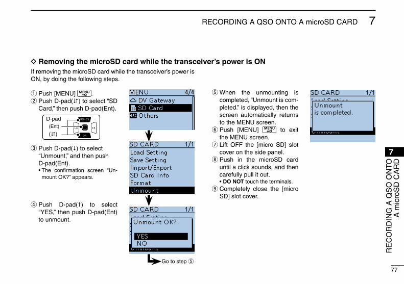
New2001
77
7rECorDING A qSo oNTo A microSD CArD
7
q Push [MENU] . w Push D-pad() to select “SD Card,” then push D-pad(Ent).
D-pad
(�)
(Ent)
e Push D-pad() to select “Unmount,” and then push D-pad(Ent).
• The confirmation screen “Un-mount oK?” appears.
r Push D-pad() to select “YES,” then push D-pad(Ent) to unmount.
t When the unmounting is completed, “Unmount is com-pleted.” is displayed, then the screen automatically returns to the MENU screen. y Push [MENU] to exit the MENU screen. u Lift oFF the [micro SD] slot cover on the side panel. i Push in the microSD card until a click sounds, and then carefully pull it out.
• do not touch the terminals. o Completely close the [micro SD] slot cover.
If removing the microSD card while the transceiver’s power is oN, by doing the following steps.
Go to step t
D Removing the microSd card while the transceiver’s power is on
rE
Co
rD
ING
A q
So
oN
To
A m
icro
SD
CA
rD

78
New2001New2001
gPS oPeRation8
New2001
■ gPS operationThe ID-51A/E has a built-in internal GPS receiver. You can check your current position and time.
D gPS receive setting Check whether or not the GPS receiver is receiving your posi-tion and time. The GPS icon blinks when searching for satellites. ➪ ➪ ➪
The GPS icon stops blinking when the minimum number of needed satellites are found.
• It may take only a few seconds to calculate your position. But de-pending on the environment, it may take a few minutes. If you have difficulties receiving, we recommend that you try a different loca-tion.
• When the “GPS Select” item is set to “Manual,” the icon does not appear.
(GPS > GPS Set > gPS Select)
Confirm the GPS icon is dis-played on the LCD.
q Push [qUICK] . w Push D-pad() to select the “GPS position” item, and then push D-pad(Ent).
D-pad
(�)
(Ent)
■ checking your gPS positionYou can check your current position.If you transmit while displaying the GPS position screen, the screen closes.But you can check your current position, rX position, and so on by touching the GPS icon while transmitting.
D displaying Position data
Go to step e

New2001
79
8GPS oPErATIoN
New2001
gPS Position screen (MY)
<contents of the gPS Position screen>
The top of the compass is North.
Your course head-ing is Northwest.
Your course head-ing is 306 degrees.
Latitude
Longitude
Grid Locator
Altitude
Speed
Time that the displayed data was acquired.
Shows the dis-played position is yours.
e The first MY GPS position screen appears. (1/5)
MEM PositionMY Position
rX Position 1
rX Position 2
ALM Position
r Push [CLr] to close the GPS Position screen.
8
GP
S o
PE
rAT
IoN

New2001
80
8 GPS oPErATIoN
New2001
■ gPS Logger functionThe GPS Logger function allows you to store the GPS po-sition data (Latitude, Longitude, Altitude, Positioning state, Course, Speed and Date) onto a microSD card, as a route.If you use this function while driving, you can check your driv-ing course on a mapping software. (Default setting is oN.)
e Push D-pad() to select “oFF.” r Push [MENU] to exit the Menu screen.
• The GPS Logger cancels.
note:• This function is oN as the default setting, if you install a
microSD card, the transceiver continuously stores the po-sition data from the GPS receiver, even if the transceiver is rebooted. To cancel this function, turn the function oFF.
While this function is ON, and when the transceiver is turned OFF, the log file will be closed. Then the trans-ceiver is turned oN and positioning is carried out by the GPS receiver, a new log file will be created.
• When the microSD card is full, this function will automati-cally pause.
<about log file>You can display your route as you move, if you import the log file into a mapping software.• You can see your route on the software map. The files may not be compatible with all mapping software.
• See the PDF type Advanced Manual for copying the log file to your PC.
turning oFF the gPS Logger function
If you do not use this function, turn oFF the function as follow-ing procedures.
q Push [MENU] to enter the Menu screen. w Push D-pad() to select “GPS Logger,” and then push D-pad(Ent).
( GPS > GPS Logger > gPS Logger)
D-pad
(�)
(Ent)
• If the item is not displayed, push D-pad() one or more times to select the page.
note: The GPS logger function requires a microSD card installation.• See page 11 for more details.

81
9ReSetting
New2001
■ ResettingThe display may occasionally display erroneous information. This may be caused externally by static electricity or by other factors. If this problem occurs, turn oFF power. After waiting a few seconds, turn oN power again. If the problem persists, perform a Partial reset or an All reset.
Be caReFUL! An All reset clears all programming and re-turns all settings to their factory defaults. See the PDF type Advanced Manual for more details.
A Partial reset resets operating settings to their default values (VFo frequency, VFo settings, menu contents) without clear-ing the items below:• Memory channel contents • Scan Edge contents• Call channel contents • Call sign memories• Message data • DTMF memory contents• GPS Memory contents • Repeater list• BC Radio Memory
q Push [MENU] to enter the Menu screen. w Push D-pad() to select “Partial reset,” and then push D-pad(Ent).
D-pad
(�)
(Ent)
( others > reset > Partial reset) • If the item is not displayed, push
D-pad() one or more times to se-lect the page.
e The “Partial reset?” dialog appears. r Push D-pad() to select “Yes,” and then push D-pad(Ent).
• The transceiver displays “PAR-TIAL rESET,” then the partial reset is completed.
default screen
Shows “PArTIAL rESET”
D Partial reset
Go to step e
9
rE
SE
TT
ING

82
New2001New2001
inFoRMation10ABoUT CE AND DoC
Hereby, Icom Inc. declares that the versions of ID-51E which have the “CE” symbol on the product, comply with the essential requirements of the radio Equipment Directive, 2014/53/EU, and the restriction of the use of certain haz-ardous substances in electrical and electronic equipment Directive, 2011/65/EU. The full text of the EU declaration of conformity is available at the following internet address:http://www.icom.co.jp/world/support
DISPoSALThe crossed-out wheeled-bin symbol on your product, literature, or packaging reminds you that in the European Union, all electrical and electronic products, batteries, and accumulators (rechargeable batteries) must be taken to designated collection locations at the end of their working life. Do not dispose of these products as unsorted municipal waste. Dispose of them according to the laws in your area.
CoUNTrY CoDE LIST• ISO 3166-1
country codes country codes
1234567891011121314151617
AustriaBelgiumBulgariaCroatiaCzech republicCyprusDenmarkEstoniaFinlandFranceGermanyGreeceHungaryIcelandIrelandItalyLatvia
ATBEBGHrCZCYDKEEFIFrDEGrHUISIEITLV
18192021222324252627282930313233
LiechtensteinLithuaniaLuxembourgMaltaNetherlandsNorwayPolandPortugalromaniaSlovakiaSloveniaSpainSwedenSwitzerlandTurkeyUnited Kingdom
LILTLUMTNLNoPLPTroSKSIESSECHTrGB

83
New2001
10INFORMATION
83
FCC INFORMATIONThis equipment has been tested and found to comply with the limits for a Class B digital device, pursuant to part 15 of the FCC Rules. These limits are designed to provide reasonable protection against harmful interference in a residential instal-lation. This equipment generates, uses and can radiate radio frequency energy and, if not installed and used in accordance with the instructions, may cause harmful interference to radio communications. However, there is no guarantee that inter-ference will not occur in a particular installation. If this equip-ment does cause harmful interference to radio or television reception, which can be determined by turning the equipment off and on, the user is encouraged to try to correct the inter-ference by one or more of the following measures: •Reorientorrelocatethereceivingantenna. •Increasetheseparationbetweentheequipmentandre-
ceiver. •Connecttheequipmentintoanoutletonacircuitdifferent
from that to which the receiver is connected. •Consultthedealeroranexperiencedradio/TVtechnician
for help.
CAUTION:Changesormodificationstothisdevice,notex-pressly approved by Icom Inc., could void your authority to operate this device under FCC regulations.
10
INF
OR
MAT
ION

84
INDEX
New2001 New2001
FFCC information .............................. 83Features ............................................. iFM repeater search function ........... xiiFormatting the microSD card ........... 18Front, top and side panels ................. 1Function display ................................. 6
gGateway repeater call .................... 58GPS Logger function ....................... 80 Log file ........................................ 80GPS operation ................................. 78 Displaying Position Data ............. 78 GPS Position screen ................... 79 GPS receive setting .................... 78 When using the GPS receiver ...... iv
HHistory, rX ....................................... 51
iInitial Setup ...................................... 10
LLocal area call ................................. 56Local setting .................................... 12Lock function ................................... 38Log file ............................................. 80
CD Starting the CD ............................. iii Supplied CD .................................. iiiCE .................................................... 82Charging Caution ........................................ viii Charging with the power oN ........ iv Charging through the [DC IN] jack ... 11 Charging time .............................. viiiCountry code list .............................. 82
dD-STAr Introduction ........................ 45 Unique features of D-STAr ......... 44Date Setting Date/Time ....................... 12DISPoSAL ....................................... 82DoC ................................................. 82Dr function ...................................... 45Dualwatch operation ........................ 32 Turning Dualwatch oN or oFF .... 33 Main band selection .................... 33DTCS Function oN .................................. 5 DTCS Code ................................. 21 DTCS Polarity ............................. 21
aAccessing repeaters ........................ 48Accessories ....................................... iiAM/FM radio mode selection ........... 41Audio volume ................................... 12Auto Position reply function ............. xi
BBattery Cautions ....................................... vii Attaching/Detaching .................... 10 Charging with the power oN ........ ivBC radio Turning oN the BC radio ........... 41
cCall Calling an individual station ........ 59Call Types Gateway repeater call ................ 58 Local area call ............................. 56 Simplex call ................................. 47Call sign Call sign Capture ........................ 55 Call sign Capture key .................. 55 Enter your call sign into the
transceiver ................................... 14 register your call sign at a gateway
repeater ....................................... 16

New2001
85
INDEX
MMain band selection ......................... 33Making a Call Gateway repeater call ................ 58 Local area call ............................. 56 Simplex call ................................. 47Memory channel Programming .............................. 42 Selecting ..................................... 43MENU screen Menu items and their details ....... 21microSD About the microSD card .............. 73 Formatting ................................... 18 Inserting ...................................... 11 removing .................................... 76Monitor function ............................... 36
ooperating band ................................ 34operating mode ............................... 35
PPartial reset ..................................... 81Playing recorded audio .................... 75Power oN ........................................ 12
QqSo recording function ................... xi recording a qSo audio .............. 74 recording a qSo onto a microSD
card .............................................. 73 Stop recording ............................. 74quick Menu ....................................... 5
Rreceiving GPS data ........................ 13reflector operation .......................... 63register your call sign at a gateway repeater ........................................... 16resetting ......................................... 81 Partial reset ................................. 81rX history Using the rX history ................... 51
SSave setting ..................................... 19Save setting data onto a microSD card ................................... 18Setting a frequency .......................... 35Setting Date/Time ............................ 12Simplex call ..................................... 47Spurious signals ............................... ivSquelch level ................................... 36
tTime Setting Date/Time ....................... 12TSqL (Tone squelch) Function oN .................................. 5 TSqL frequency .......................... 21Transmit power levels ...................... 40Transmitting ..................................... 39Troubleshooting ............................... 61Tuning step ...................................... 34
UUpdating the repeater list ................ 69
VVoice TX function .............................. xi
IND
EX

86
INDEX For MENU ITEMS
New2001 New2001
cCall Sign ............................................................................. [root] 24Charging (Power oN) .................................................[Function>] 28CI-V .........................................................................[Function>] 28CI-V Address .................................................... [Function>CI-V>] 28CI-V Baud rate ................................................ [Function>CI-V>] 28CI-V Transceive ................................................ [Function>CI-V>] 28CI-V (DATA Jack) .............................................. [Function>CI-V>] 28Clone ............................................................................[others>] 31Clone Master Mode ........................................... [others>Clone>] 31Clone Mode ....................................................... [others>Clone>] 31Comment .......................... [GPS>GPS TX Mode>D-PrS (DV-A)] 24CSV Format ........................................................ [qSo/rX Log>] 27CSV Format ........................................[SD Card>Import/Export>] 31
dDate ............................................[qSo/rX Log>CSV Format>] 27Date ............................ [SD Card>Import/Export/CSV Format>] 31Data Extension ................. [GPS>GPS TX Mode>D-PrS (DV-A)] 24Data Speed .................................................................[Function>] 28Date/Time .................................................................. [Time Set>] 30DIAL SPEECH ...........................................................[SPEECH>] 26Dial Speed-UP ............................................................[Function>] 27Digital Code ........................................................... [DUP/ToNE>] 21Digital Monitor ............................................................... [DV Set>] 26Digital repeater Set ..................................................... [DV Set>] 26Display ................................................................................ [root] 28Display Language .........................................................[Display>] 29Display Unit ..................................................................[Display>] 29DTCS Code ........................................................... [DUP/ToNE>] 21DTCS Polarity ........................................................ [DUP/ToNE>] 21DTMF Memory ..................................................[DTMF/T-CALL>] 27DTMF Speed .....................................................[DTMF/T-CALL>] 27DTMF/T-CALL ..................................................................... [root] 27
aActive Band ................................................................[Function>] 28<<Access Point Mode>>.......................................[DV Gateway>] 30Alarm Area (Group) ......................................[GPS>GPS Alarm>] 23Alarm Area (rX/Memory) .............................[GPS>GPS Alarm>] 23Alarm Select .................................................[GPS>GPS Alarm>] 23All reset ............................................................ [others>reset>] 31Alphabet ....................................................................[SPEECH>] 26Altitude .............................. [GPS>GPS TX Mode>D-PrS (DV-A)] 24Altitude/Distance ......................................[Display>Display Unit>] 29Auto Mute ......................................... [BC radio>BC radio Set>] 23Auto Power oFF ........................................................ [Time Set>] 30Auto repeater ............................................................[Function>] 27Auto reply .................................................................... [DV Set>] 25
BBacklight .......................................................................[Display>] 28Backlight Timer .............................................................[Display>] 28Band Edge Beep ......................................................... [Sounds>] 30Bank Link ......................................................................... [Scan>] 21Barometric ...............................................[Display>Display Unit>] 29BC radio ............................................................................ [root] 23BC radio Level ............................................................ [Sounds>] 29BC radio Memory .................................................... [BC radio>] 23<<BC radio Mode>> ................................................ [BC radio>] 23<<BC radio oFF>> .................................................. [BC radio>] 23<<BC radio oN>> ................................................... [BC radio>] 23BC radio Set ............................................................ [BC radio>] 23Beep Level ................................................................... [Sounds>] 30Beep/Vol Level Link ..................................................... [Sounds>] 30BK ........................................................................... [DV Set>] 26Busy LED ......................................................................[Display>] 29Busy Lockout ..............................................................[Function>] 27

New2001
87
INDEX For MENU ITEMS
DUP/ToNE... ...................................................................... [root] 21During rX/Standby ....................... [Function>remote MIC Key>] 27During TX ..................................... [Function>remote MIC Key>] 27DV Auto Detect ............................................................. [DV Set>] 26DV Auto reply ......................................................[Voice Memo>] 22DV Data TX ................................................................... [DV Set>] 25DV Fast Data ................................................................ [DV Set>] 25DV Gateway ........................................................................ [root] 30DV Memory ......................................................................... [root] 24DV rX Backlight ...........................................................[Display>] 29DV Set ................................................................................ [root] 25D-PrS (DV-A) ..........................................[GPS>GPS TX Mode>] 24
eEarphone Mode ........................................................... [Sounds>] 30Export .................................................[SD Card>Import/Export>] 31EMr ........................................................................... [DV Set>] 26EMr AF Level ............................................................... [DV Set>] 26
FFast Data ............................................... [DV Set>DV Fast Data>] 25File Split ................. [Voice Memo>qSo recoder>recoder Set>] 22FM Antenna ...................................... [BC radio>BC radio Set>] 23Format ........................................................................[SD Card>] 31Function .............................................................................. [root] 27
gGPS ................................................................................. [root] 23GPS Alarm .......................................................................[GPS>] 23GPS Auto TX ....................................................................[GPS>] 24GPS Data Speed ................................... [DV Set>DV Fast Data>] 25GPS Indicator ...................................................[GPS>GPS Set>] 23GPS Information ...............................................................[GPS>] 23GPS Logger ......................................................................[GPS>] 23GPS Logger ................................................ [GPS>GPS Logger>] 23<<GPS Logger only>> ............................... [GPS>GPS Logger>] 24
GPS Memory ....................................................................[GPS>] 23GPS Message .................. [GPS>GPS TX Mode>NMEA (DV-G)] 24GPS out (To DATA jack) ...................................[GPS>GPS Set>] 23GPS Position ....................................................................[GPS>] 23GPS Select .......................................................[GPS>GPS Set>] 23GPS Sentence .................. [GPS>GPS TX Mode>NMEA (DV-G)] 24GPS Set ............................................................................[GPS>] 23GPS Time Correct ..................................................... [Time Set>] 30GPS TX Mode...................................................................[GPS>] 24
HHeadset Select ................................................. [Function>VoX>] 28Heterodyne .................................................................[Function>] 28Home CH Beep ........................................................... [Sounds>] 30
iImport .................................................[SD Card>Import/Export>] 31Import/Export ..............................................................[SD Card>] 31Information .....................................................................[others>] 31
KKey Lock .....................................................................[Function>] 27Key-Touch Beep .......................................................... [Sounds>] 30
LLatitude/Longitude ...................................[Display>Display Unit>] 29LCD Contrast ................................................................[Display>] 28LCD Dimmer .................................................................[Display>] 28Load Setting ...............................................................[SD Card>] 30
MManual Position ................................................[GPS>GPS Set>] 23MIC Gain (External) ....................................................[Function>] 28MIC Gain (Internal) .....................................................[Function>] 28MoDE SPEECH ........................................................[SPEECH>] 26Monitor ........................................................................[Function>] 27MY: ........................................................................ [Call Sign>] 24My Call Sign ........................................................... [My Station>] 25
IND
EX
Fo
r M
EN
U IT
EM
S

88
INDEX For MENU ITEMS
New2001 New2001
My Station ........................................................................... [root] 25n
<<New File>> ...................................... [SD Card>Save Setting>] 30NMEA (DV-G) ..........................................[GPS>GPS TX Mode>] 24
ooffset Freq ............................................................. [DUP/ToNE>] 21opening Message ........................................................[Display>] 29others ................................................................................. [root] 31
PPartial reset ...................................................... [others>reset>] 31Pause Timer .................................................................... [Scan>] 21Play Files ....................................[Voice Memo>qSo recorder>] 21Play Files ................................... [Voice Memo>Voice recorder>] 22Player Set ...................................[Voice Memo>qSo recorder>] 22Player Set .................................. [Voice Memo>Voice recorder>] ..22Power Save .................................................................[Function>] 27Power Save (BC radio) .................... [BC radio>BC radio Set>] 23Power Save (Internal GPS)...............................[GPS>GPS Set>] 23Program Link ................................................................... [Scan>] 21Program Skip ................................................................... [Scan>] 21PTT Auto rEC .....[Voice Memo>qSo recorder>recorder Set>] 22PTT Lock ....................................................................[Function>] 27
QqSo Log ............................................................. [qSo/rX Log>] 27qSo recorder ......................................................[Voice Memo>] 21qSo/rX Log ....................................................................... [root] 27
Rr1: ........................................................................ [Call Sign>] 25r2: ........................................................................ [Call Sign>] 25rainfall .....................................................[Display>Display Unit>] 29rEC Mode ...........[Voice Memo>qSo recorder>recorder Set>] 22<<rEC Start>> ...........................[Voice Memo>qSo recorder>] 21 record ....................................... [Voice Memo>Voice recorder>] 22
record ....................................................................... [Voice TX>] 22record Interval ........................................... [GPS>GPS Logger>] 23recorder Set ..............................[Voice Memo>qSo recorder>] 22recorder Set ............................. [Voice Memo>Voice recorder>] 22record Sentence ........................................ [GPS>GPS Logger>] 24remote MIC Key ........................................................[Function>] 27repeat Time ................................................. [Voice TX>TX Set>] 22<<repeat TX>> ......................................................... [Voice TX>] 22repeater List .........................................................[DV Memory>] 25repeater Tone ....................................................... [DUP/ToNE>] 21reply Position Display ..................................................[Display>] 29reset ............................................................................[others>] 31resume Timer ................................................................. [Scan>] 21rX Bass ..................................................[DV Set>Tone Control>] 25rX Bass Boost .......................................[DV Set>Tone Control>] 25rX Call Sign .................................................................[Display>] 29rX Call Sign SPEECH ..............................................[SPEECH>] 26RX Call Sign Write ........................................................ [DV Set>] 26rX History .......................................................................... [root] 24rX History Log ................................................... [qSo/rX Log>] 27rX Message .................................................................[Display>] 29rX rEC Condition ...[Voice Memo>qSo recorder>recorder Set>] 22rX record (rPT) ......................................................... [DV Set>] 26RX Repeater Write ....................................................... [DV Set>] 26rX Treble ................................................[DV Set>Tone Control>] 25rX01: ..................................................................... [rX History>] 24rX>CS SPEECH .......................................................[SPEECH>] 26[rX>CS] Key ................................................................ [DV Set>] 26
SSave Setting ...............................................................[SD Card>] 30Scan ................................................................................. [root] 21 Scan Stop Beep ........................................................... [Sounds>] 30Scope AF output ......................................................... [Sounds>] 30

New2001
89
INDEX For MENU ITEMS
Scroll Speed .................................................................[Display>] 29SD Card .............................................................................. [root] 30SD Card Info ...............................................................[SD Card>] 31Separator/Decimal .........................[qSo/rX Log>CSV Format>] 27Separator/Decimal ......... [SD Card>Import/Export/CSV Format>] 31<<Single TX>> ........................................................... [Voice TX>] 22Skip Time ................. [Voice Memo>qSo recorder>Player Set>] 22Sound ................................................................................. [root] 29SPEECH ............................................................................. [root] 26SPEECH Language ...................................................[SPEECH>] 26SPEECH Level ..........................................................[SPEECH>] 26SPEECH Speed ........................................................[SPEECH>] 26Speed ......................................................[Display>Display Unit>] 29SSID ............................... [GPS>GPS TX Mode>D-PrS (DV-A)] 24Standby Beep .............................................................. [Sounds>] 30Sub Band Mute ............................................................ [Sounds>] 30System Language .........................................................[Display>] 29
tTemperature ............................................[Display>Display Unit>] 29Temporary Skip Timer...................................................... [Scan>] 21<<Terminal Mode>> .............................................[DV Gateway>] 30Time Set ............................................................................. [root] 30Time Stamp ...................... [GPS>GPS TX Mode>D-PrS (DV-A)] 24Time-out Timer ...........................................................[Function>] 27Tone Burst ............................................................. [DUP/ToNE>] 21Tone Control ................................................................. [DV Set>] 25TSqL Freq ............................................................. [DUP/ToNE>] 21TX Bass ..................................................[DV Set>Tone Control>] 25TX Call Sign ..................................................................[Display>] 29TX Delay (PTT) ...................................... [DV Set>DV Fast Data>] 25TX Message ........................................................... [My Station>] 25
TX Monitor .................................................... [Voice TX>TX Set>] 22TX Set ........................................................................ [Voice TX>] 22TX Treble ................................................[DV Set>Tone Control>] 25
UUnmount .....................................................................[SD Card>] 31Unproto Address ............... [GPS>GPS TX Mode>D-PrS (DV-A)] 24Ur: ........................................................................ [Call Sign>] 24UTC offset ................................................................. [Time Set>] 30
VVersion .......................................................[others>Information>] 31Voice Memo ........................................................................ [root] 21Voice recorder ....[Voice Memo>qSo recorder>recorder Set>] 22Voice TX ............................................................................. [root] 22Voltage .......................................................[others>Information>] 31Voltage (Power oN) ......................................................[Display>] 29Volume Select .............................................................. [Sounds>] 29VoX .........................................................................[Function>] 28VoX ............................................................... [Function>VoX>] 28VoX Delay ........................................................ [Function>VoX>] 28VoX Level ......................................................... [Function>VoX>] 28VoX Time-out Timer ........................................ [Function>VoX>] 28
WWind Speed .............................................[Display>Display Unit>] 29
YYour Call Sign ........................................................[DV Memory>] 24
IND
EX
Fo
r M
EN
U IT
EM
S

90
SPECIFICATIoNS
New2001 New2001
■ general• Frequency coverage: (unit: MHz)
TX rXeUR 144 ~ 146, 430 ~ 440 144 ~ 146, 430 ~ 440USa 144 ~ 148, 430 ~ 450*1 108 ~ 174*2, 380 ~ 479*1
aLL — BC band (AM): 0.520 ~ 1.710BC band (FM): 76.0 ~ 108.0*3
*1 Guaranteed 440 ~ 450 MHz only *2 Guaranteed 144 ~ 148 MHz only*3 88.0 ~ 108.0 MHz for the USA version.
tiP: The SUB band audio signal may be muted, depend-ing on the combination of operating band and mode.
• Modes: FM (F2D/F3E), AM (A3E)*, DV (F7W) *rx only
• Number of memory channels: 554 (including 50 scan edges and 4
call channels)
• Number of BC band memory channels: 500• Usable temp. range: –20°C ~ +60°C, –4°F ~ +140°F• Tuning steps: 1, 5, 6.25, 8.33, 9, 10, 12.5, 15, 20,
25, 30, 50, 100, 125, and 200 kHz * The selectable steps may differ, depending on the selected fre-
quency band or operating mode.• Frequency stability: ±2.5 ppm
(–20°C ~ +60°C, –4°F ~ +140°F)• Power supply: 10 ~ 16 V DC for external DC pow-
er, or specified Icom’s battery pack• Digital transmission speed: 4.8 kbps• Voice coding speed: 2.4 kbps
• Current drain (with BP-271): TX (at 5 W output) Less than 2.5 A rX Max. output FM Less than 350 mA (Internal speaker)
Less than 200 mA (External speaker)
DV Less than 450 mA (Internal speaker)
Less than 300 mA (External speaker)
• Antenna impedance: 50 W (SMA)• Dimensions: 58.0(W)×105.4(H)×26.4(D) mm, (projections not included) 2.3(W)×4.1(H)×1.0(D) in• Weight (approximately): 255 g, 9 oz (including battery pack and antenna)
■ transmitter• Modulation system: FM Variable reactance frequency
modulation DV GMSK reactance frequency
modulation• Output power: High 5.0 W, Mid. 2.5 W,
Low2 1.0 W, Low1 0.5 W, S-Low 0.1 W (Typical)
• Max. freq. deviation: ±5.0 kHz (FM wide) ±2.5 kHz (FM narrow)
• Occupied bandwidth: Less than 6.0 kHz (DV)
• Spurious emissions: Less than –60 dBc at High/Mid. Less than –13 dBm at Low2/Low1/S-Low
• Ext. mic. impedance: 2.2 kW

New2001
91
SPECIFICATIoNS
■ Receiver• Receive system: Double-conversion superhetero-
dyne• Intermediate frequencies: A Band 46.35 MHz (1st IF) 450 kHz (2nd IF) B Band 61.65 MHz (1st IF) 450 kHz (2nd IF)• Sensitivity (except spurious points):
AM (1 kHz 30% MoD; 10 dB S/N) 0.520 to 0.995 MHz Less than 3.2 μV 1.000 to 1.710 MHz Less than 1.8 μV 108.000 to 136.995 MHz Less than 1.8 μV
FM (1 kHz/±3.5 kHz Dev.; 12 dB SINAD) 137.0 to 174.0 MHz Amateur band only
Except for Amateur bandLess than 0.18 μVLess than 0.32 μV
380.0 to 479.0 MHz Amateur band only
Except for Amateur bandLess than 0.18 μVLess than 0.32 μV
WFM (1 kHz/±52.5 kHz Dev.; 12 dB SINAD) 76.0 to 81.9 MHz Less than 3.2 μV 82.0 to 108.0 MHz Less than 1.8 μV
DV (PN9/GMSK 4.8 kbps; BEr 1%) 137.0 to 174.0 MHz Amateur band only Less than 0.28 μV 380.0 to 479.0 MHz Amateur band only Less than 0.28 μV
• Audio output power (at 10% distortion): Internal speaker More than 0.4 W into a 16 Ω load External speaker More than 0.2 W into an 8 Ω load• Selectivity: FM (Wide) More than 55 dB FM (Narrow), DV More than 50 dB• Ext. speaker impedance: 8 W
(3-conductor 3.5 mm, 1⁄8˝ (d))• Spurious and image rejection ratio: More than 60 dB• Squelch Sensitivity (except spurious points):
AM (1 kHz 30% MoD, 10 dB S/N) (threshold) 0.520 to 0.995 MHz Less than 3.2 μV 1.000 to 1.710 MHz Less than 1.8 μV 108.000 to 136.995 MHz Less than 1.8 μV
FM (1 kHz/±3.5 kHz Dev., 12 dB SINAD) (threshold) 137.0 to 174.0 MHz Amateur band only
Except for Amateur bandLess than 0.18 μVLess than 0.32 μV
380.0 to 479.0 MHz Amateur band only
Except for Amateur bandLess than 0.18 μVLess than 0.32 μV
WFM (1 kHz/±52.5 kHz Dev., 12 dB SINAD) (threshold) 76.0 to 81.9 MHz Less than 3.2 μV 82.0 to 108.0 MHz Less than 1.8 μV
SP
EC
IFIC
ATIo
NS

MEMo
New2001 New2001

MEMo
New2001

1-1-32 Kamiminami, Hirano-ku, osaka 547-0003, Japan
New2001
A7331H-1EX-1Printed in Japan© 2016–2018 Icom Inc.