VHF Communication Antennas - Dallas Avionics, · PDF file ·...
31
142 EDO Corp./Dorne & Margollin 214.320.9770 Dallas Avionics 800.527.2581 Avionics & Accessories DMC50 series VHF Antennas The unique design of this blade antenna offers mechanical properties far exceeding those of any competitive product and offers the best available electrical performance. The DMC50 is the lowest cost, lightest weight and strongest blade antenna in current use on commercial jet aircraft. Features • Maximum protection against corona and direct impact p-static • Unique ruggedness (withstands 10 G at resonance for one million cycles) • Lightning protection of associated equipment as well as antenna • Factory replaceable leading edge • An extra strength version for use on unimproved runway (stainless steel leading edge; weight increase 14 oz) (Model designation change –/S) • Hot air duct for use, when required, in top locations directly forward of a jet engine as on the Boeing 727 or a Douglas DC-10 P/N DMC50 OUTLINE DIMENSIONS Inches 0.34 1.22 0.25 2.78 CONSULT FACTORY FOR AVAILABLE MOUNTING BOLT PATTERNS -1 SHOWN - + 3.62 16.0 AIR OUTLET -1 AND -3/B 10.87 16.5 0.18 DIA DRAIN REPLACEABLE ALUMINUM ALLOY 38° 30' 0.85 ANTENNA MAY BE 0.128 DIA DRILLED FORE OR AFT FOR SENSE ANTENNA ATTACHMENT FIBERGLASS Specifications subject to change without notice. VHF Communication Antennas VHF Communication Antennas Electrical Mechanical Environmental Specifications Frequency Range 116 to 156 MHz VSWR < 2:1 Power Rating -1 & -3/B models 1 kW CW; -2 & -11A models 500 W CW @ 75,000’ Impedance RF 50 OHMS DC Short Circuit Polarization Vertical Radiation Pattern Omnidirectional (equivalent to a vertical stub) Weight < 3.5 lbs. Drag (35,000' Mach 0.89) 3 lbs. Lightning Protection Exceeds the requirements of spec MIL-A-9094C Erosion Resistance The antennas have metal leading edges FAA TSO-37d, -38d, CAT F2 ABCXXFXXSXXXXXXXXXX Side Load 12 psi Vibration 10 G at res for 1 million cycles Shock 30 G Hot Air Duct Antenna will operate 1 hr. minimum with 400°F air; withstand 500°F air continuously in atmosphere below 32°F
-
Upload
nguyenquynh -
Category
Documents
-
view
224 -
download
3
Transcript of VHF Communication Antennas - Dallas Avionics, · PDF file ·...

142
ED
O C
orp
./Do
rne
& M
arg
ollin
2 1 4 . 3 2 0 . 9 7 7 0 Dal las Av ion ics 8 0 0 . 5 2 7 . 2 5 8 1
Avio
nics &
Accesso
ries
DMC50 series VHF AntennasThe unique design of this blade antenna offers mechanical properties far exceeding those of any competitive product and offers the best available electrical performance. The DMC50 is the lowest cost, lightest weight and strongest blade antenna in current use on commercial jet aircraft.
Features• Maximum protection against corona and direct impact p-static• Unique ruggedness (withstands 10 G at resonance for one million cycles)• Lightning protection of associated equipment as well as antenna• Factory replaceable leading edge• An extra strength version for use on unimproved runway (stainless steel leading edge; weight increase 14 oz) (Model designation change –/S) • Hot air duct for use, when required, in top locations directly forward of a jet engine as on the Boeing 727 or a Douglas DC-10 P/N DMC50
OUTLINE DIMENSIONS
Inches
0.34
1.22
0.25
2.78
CONSULT FACTORY
FOR AVAILABLE
MOUNTING BOLT
PATTERNS
-1 SHOWN
- +
3.62
16.0
AIR OUTLET
-1 AND -3/B
10.87
16.5
0.18 DIA DRAIN
REPLACEABLE
ALUMINUM ALLOY
38° 30'
0.85
ANTENNA MAY BE 0.128 DIA
DRILLED FORE OR AFT FOR
SENSE ANTENNA ATTACHMENT
FIBERGLASS
Specifications subject to change without notice.
VHF Communication AntennasVHF Communication Antennas
Electrical
Mechanical
Environmental
Specifications
Frequency Range 116 to 156 MHzVSWR < 2:1Power Rating -1 & -3/B models 1 kW CW; -2 & -11A models 500 W CW @ 75,000’ Impedance RF 50 OHMS DC Short CircuitPolarization VerticalRadiation Pattern Omnidirectional (equivalent to a vertical stub)
Weight < 3.5 lbs.Drag (35,000' Mach 0.89) 3 lbs.Lightning Protection Exceeds the requirements of spec MIL-A-9094CErosion Resistance The antennas have metal leading edgesFAA TSO-37d, -38d, CAT F2 ABCXXFXXSXXXXXXXXXX
Side Load 12 psiVibration 10 G at res for 1 million cyclesShock 30 GHot Air Duct Antenna will operate 1 hr. minimum with 400°F air; withstand 500°F air continuously in atmosphere below 32°F

143
ED
O C
orp
./D
orn
e &
Ma
rgo
llin
2 1 4 . 3 2 0 . 9 7 7 0 Dal las Av ion ics 8 0 0 . 5 2 7 . 2 5 8 1
Avi
on
ics
& A
cces
sori
es
1.22(3.099)
0.25(0.635)
2.78(7.061)
0.34(90.864)
OUTLINE DIMENSIONSInches (Centimeters)
FWD
3.62(9.195)1.50 R
(3.310)
1.00 R(2.50)
0.19 DIA (483)DRAIN HOLE THROUGHNEAR SIDE ONLYTYP 2 PL
0.85(2.159)
10.875(27.6225)
1.00(2.540)
16.0(40.64)
Specifications subject to change without notice.
2.96(7.518)
9.15(23.241)
0.262 (0.6528) DIA10 HOLES CSK 100∞TO 0.510 (1.2954) DIAFAR SIDE CSKS
1.640(4.1656)
1.280(3.2512)
9.000(22.8600)
6.000(15.2400)
4.000(10.1600)
3.000(7.6200)
12.48(31.953)
1.85(4.699)
1.560(3.9624)
1.840(4.6736)
O-RING GROOVE
DM C50-17 VHF AntennaThe DM C50-17 series VHF Communication Antennas have incorporated design improvements to enhance corona threshold, corrosion protection, and drag characteristics.
The DM C50-17 series provides the lightest weight and strongest blade antenna at lower cost for current use on commercial jet aircraft.
In addition to its low initial price, further cost reductions are realized due to the weight and drag reduction of the antenna. The fuel saving per ship-set is calculated to be 160.5 gallons per aircraft per year.
The DM C50-17 antenna has been selected as original equipment for the Boeing 757 and 767, and 777 aircraft. Other models in the DM C50-17 series can also be used on Boeing 707, 727, 737, 747; Douglas DC-8, DC-9, and DC-10; Aerospatiale A300 series; and other commercial aircraft. Many of the DM C50-17 series are interchangeable with other types of antennas presently in use.P/N DM C50-17
VHF Communication AntennasVHF Communication Antennas
Electrical
Mechanical
Specifications
Frequency Range 116 to 156 MHzVSWR 2.0:1Power 1 kW CWImpedance 50 OHMSPolarization VerticalRadiation Pattern Omnidirectional (equivalent to a vertical stub)
Weight 3.3 lbs.Connectors C Female

144
ED
O C
orp
./Do
rne
& M
arg
ollin
2 1 4 . 3 2 0 . 9 7 7 0 Dal las Av ion ics 8 0 0 . 5 2 7 . 2 5 8 1
Avio
nics &
Accesso
ries
Electrical
Mechanical
Specifications
FrequencyRange 450 to 470 MHzVSWR < 2.0:1 454 to 459 MHz < 2.5:1 450 to 470 MHzEfficiency > 85%Impedance 50 OHMSPower 100 WattsPolarization VerticalRadiation Pattern OmnidirectionalGain Equal to quarter wave stub
Connector N (female)Weight 8 oz. maximum (0.22 Kg)Finish WhiteMax Air Speed 0.85 MachTemp Range -65°F to +250°FAltitude 70,000’Drag 5.5 oz. @ 25,000’ @ 0.85 Mach
OUTLINE DIMENSIONSInches (Centimeters)
1.062 TYP(2.70)
0.531 TYP(0.35)
1.187(3.01)
0.218 DIA (0.55) CSK 100∞ x0.375 DIA (0.95) 4 PL
2.375(6.03)
1.89 REF(4.8)
0.25 R TYP(0.64)
0.12(0.30)
0.62(1.57)
3.50 MAX(8.89)
2.18 REF(5.54)4.9 MAX
(12.45)
0.50 R TYP(1.27)
0.87(2.21)
1.75(4.45)
0.18(0.46)
C
Specifications subject to change without notice.
DM C57-1 Low Profile Metal Blade Radio Telephone AntennaThe DM C57-1 antenna has achieved a design breakthrough that has not compromised performance. Previous designs were 6 to 7" high and heavier. The DM C57-1 is only three and a half inches high and weighs 8 ounces.
The DM C57-1 operates with all airborne radio telephone systems in the 450-470 MHz frequency range. Reduced maintenance costs are achieved through the use of this low profile, all metal blade as a result of its unequalled mechanical strength and built-in reliability. The DM C57-1 is currently in use and field proven on business and commercial aircraft. This low drag antenna has extremely high side load strength and its construction is completely sealed to prevent damage from moisture, Skydrol, or other contaminants.P/N DM C57-1
VHF Communication AntennasVHF Communication Antennas

145
ED
O C
orp
./D
orn
e &
Ma
rgo
llin
2 1 4 . 3 2 0 . 9 7 7 0 Dal las Av ion ics 8 0 0 . 5 2 7 . 2 5 8 1
Avi
on
ics
& A
cces
sori
esDM C60 Series VHF AntennasThe DM C60 is a vertically polarized VHF communications antenna designed for either top or bottom fuselage mounting. The antenna covers the frequency range of 118-137 MHz (-1) or 116-152 MHz (-17) for both transmitting and receiving applications. Electrical elements of the antenna are completely sealed by foamed-in-place resin within an outer fiberglass housing. As a result, the antenna is rugged enough for use on both commercial and general aviation aircraft.P/N DM C60-
VHF Communication AntennasVHF Communication Antennas
Electrical
Mechanical
Specifications
Frequency Range -1 118 to 137 MHzFrequency Range -17 116 to 152 MHz VSWR 2.0:1 maximumPower 50 WattsImpedance 50 OHMS Polarization VerticalRadiation Pattern OmnidirectionalGain Equivalent to a quarter wave stubDrag, Sea Level @ 250 MPH 0.5 lbs.Side Load Strength To 3 psiAltitude Performance 35,000’TSO C37d & C38dD0160C ENV CAT. F2-ABCXXXXXXXXXXXXXXXXDC Resistance Grounded
Weight 1.6 lbs.Finish WhiteConnectors BNC (female)
OUTLINE DIMENSIONSInches (Centimeters)
FWD
0.50 DIA
0.125
1.31
0.375 0.375
22
7.2(18.80)
2.50 1.75
6.40
0.50(1.27)
1.25
0.225 DIA, 6 HOLES
72
0.48
0.963.5 MAX(8.56)1.91
NOTE 1
11.9(30.25)
8.65(21.80)
2.78
NOTE: A DENOTES LOCATION OF HOLE
0.625 DIA
1.750
0.875 0.687
6 "A" HOLESFOR NO. 10 SCREWS
A
A A
A
2.7816.406
1.2502.500
1.375
A
A
1.91 (-1)2.12 (-17)
Specifications subject to change without notice.
Notes: 1. DM C60-1 AS SHOWN DM C60-17-1 DIMENSION IS 2.12 IN. MAX (5.33 cm)

146
ED
O C
orp
./Do
rne
& M
arg
ollin
2 1 4 . 3 2 0 . 9 7 7 0 Dal las Av ion ics 8 0 0 . 5 2 7 . 2 5 8 1
Avio
nics &
Accesso
ries
Electrical
Mechanical
Environmental
Specifications
Frequency Range 118 to 137 MHz; DM C63-1/A, DM C63-2/A 138 to 174 MHz; DM C63-3/A, DM C63-4/A VSWR 2.0:1 DM C63-1/A 3.0:1 DM C63-2 3.5:1 DM C63-3/A 3.0:1 DM C63-4/A Power 50 WattsImpedance 50 OHMS Polarization VerticalRadiation Pattern OmnidirectionalGain Equivalent l/4 stubTSO C37d & C38d
Weight 8 oz.Finish WhiteConnectors BNC (female)
Per D0160c F2-ABCXXXXXXXXXXXXXXXX
DM C63 Series VHF AntennaThe DM C63 series antennas are VHF communication antennas designed for high mechanical strength with machine tapered aluminum alloy radiating elements. These vertically polarized antennas cover the frequency range of 118-137 or 138-174 MHz for both transmitting and receiving applications.
The DM C63-1/A and DM C63-4/A are designed for mounting on top of the fuselage. The DM C63-2 and DM C63-3/A are low profile "bentback" radiating element designs for mounting on the bottom of the fuselage. They are well suited for helicopter installations.
All DM C63 series antennas are supplied with a gasket and a doubler plate. P/N DM C63-
OUTLINE DIMENSIONSInches (Centimeters)
Notes: 1. 0.032 thick core gasket supplied with antenna 2. Doubler plate supplied with antenna
AIRCRAFTSKIN (REF)
4.63(11.76)
8.0 MAX(20.32)
60°
20.8 MAX (52.83)
20.50 MAX(52.07)
AIRCRAFTSKIN (REF)
4.63(11.76)
60°60°AIRCRAFTSKIN (REF)
16.42 REF (41.71)
8.1 MAX(20.57)
4.63(11.76)
AIRCRAFTSKIN (REF)
4.63(11.76)
60°
17.0(43.18)
0.562 DIA (1.43)
0.218 DIA (0.55) CSK 100° x0.440 DIA (1.118) FAR SIDE 3 PLACES
2.19 (5.56)
1.375 (3.49)
0.687 (1.74)1.375
(3.49)3.25
(8.26)
Specifications subject to change without notice.
DM C63–1/ADM C63–4/A
DM C63–3/A
DM C63–2
VHF Communication AntennasVHF Communication Antennas

147
ED
O C
orp
./D
orn
e &
Ma
rgo
llin
2 1 4 . 3 2 0 . 9 7 7 0 Dal las Av ion ics 8 0 0 . 5 2 7 . 2 5 8 1
Avi
on
ics
& A
cces
sori
esDM C70 Series VHF 360/720 Channel Broadband AntennasThe DM C70 series VHF Communication Antennas are designed for top or bottom installation on high-performance, single, twin and turbo engine fixed and rotary wing aircraft. These uniquely designed antennas offer mechanical strength and high-electrical efficiency to provide maximum reliability and full 360/720 channel transceiver operation. The lightweight profile is unobtrusive, resists icing and offers low drag. The DM C70-3 is directly interchangeable with the following part numbers: C598501-0104, VF 10-210, CI 109, and CI 121. The DM C70-4 which supersedes the DM C70-2, is specifically designed for bottom installations, where ground clearance does not permit the use of other DM C70 series antennas. The DM C70-4 provides a higher degree of efficiency to assure maximum performance from your transceiver.
The DM C70-6, and DM C70-9 variants of the DM C70-1/A, have a different mounting hole pattern and connector location. All other characteristics remain the same.P/N DM C70-
0.170 (0.432)4 MTG HOLES CSK 100∞ ON
FARSIDE
0.81(2.057)
1.62(4.114)
2.58(6.55)
0.875(2.222)
1.750(4.445)
1.00(2.540)
4.26(10.820)
FWD
FWD
0.203 DIA (0.516)CSK 100∞ x 390 (0.990)
DIA(FARSIDE)
5.37 (13.65)
2.50(6.35)
1.750(4.45)
0.750(1.91)
0.75(1.91)
1.50(3.81)
3.62
1.125(2.86)
0.875(2.22)
1.750(4.45)
MOUNT USING FOUR NO. 10STAINLESS STEEL SCREWS
MOUNTING HOLE PATTERN
Inches (Centimeters)
Notes: 1. 0.080 MIN Thk gasket supplied with antenna. 0.130 MAX 2. Doubler plate supplied with antenna.
60
20.50(52.07)MAX
15.00(38.10)MAX
60
15.00(38.10)MAX
608.90
(22.61)MAX
60
OUTLINE DIMENSIONS
Inches (Centimeters)
FWD
DM C70–1/ADM C70–3DM C70–4
DM C70–6DM C70–9
DM C70–3
DM C70–4
DM C70–1/A
DM C70–6DM C70–9
VHF Communication AntennasVHF Communication Antennas
Specifications subject to change without notice.
Electrical
Mechanical
Specifications
Frequency Range 118 to 137 MHzVSWR 2.0:1 DM C70, -1/A, -3, -6, -9 2.5:1 DM C70-4 Polarization VerticalPower 50 WattsImpedance 50 OHMSRadiation Patterns OmnidirectionalConnectors BNC (female)
Weight 12 oz. (0.34 Kg)Finish White polyurethaneTSO C37d, C38dD0160c ENV CAT F2-ABCXWFDXSXXXXXXXXXXSpeed Rating DM C70-1/A, -4, -6, -9, 400 MPH DM C70-3, 250 MPH
148
ED
O C
orp
./Do
rne
& M
arg
ollin
2 1 4 . 3 2 0 . 9 7 7 0 Dal las Av ion ics 8 0 0 . 5 2 7 . 2 5 8 1
Avio
nics &
Accesso
ries
OUTLINE DIMENSIONSInches
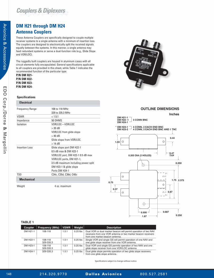
Coupler Frequency (MHz) VSWR Weight DescriptionDM H21-1 108-118 1.5:1 0.25 lbs Dual VOR or dual marker beacon will permit operation of two NAV receivers from one VOR antenna or two marker beacon receivers from one marker beacon antenna.DM H22-1 108-118 1.5:1 0.25 lbs Single VOR and single GS will permit operation of one NAV and 329-335.3 one glide slope receiver from one VOR antenna.DM H23-1 108-118 1.5:1 0.25 lbs Dual VOR and single GS permits operation of two NAV and one 329-335.3 glide slope receiver from one VOR/LOC antenna.DM H24-1 329-335.3 1.5:1 0.25 lbs Dual glide slope permits operation of two glide slope receivers from one glide slope antenna.
DM H21-1 DM H22 -1 3 CONN BNC DM H24-1
* DM H23-1 4 CONN, 2 EACH END BNC DM H23-2 4 CONN, 3 EACH END BNC AND 1 TNC
*
*
0.44
0.47TYP0.203 DIA (2 HOLES)
0.250
0.2500.687
0.75
0.370.87
0.5001.87
1.03
1.75
TABLE 1
Specifications subject to change without notice.
2.375
DM H21 through DM H24 Antenna CouplersThese Antenna Couplers are specifically designed to couple multiple receiver systems to a single antenna with a minimum of insertion loss. The couplers are designed to electronically split the received signals equally between the systems. In this manner, a single antenna may feed redundant systems or serve a dual-function role (e.g., Glide Slope and VOR/LOC).
The ruggedly built couplers are housed in aluminum cases with all circuit elements fully encapsulated. General specifications applicable to all couplers are provided in this sheet, while Table 1 indicates the recommended function of the particular type.P/N DM H21-P/N DM H22-P/N DM H23-P/N DM H24-
Couplers & DiplexersCouplers & Diplexers
Electrical
Mechanical
Specifications
Frequency Range 108 to 118 MHz 329 to 335.3 MHzVSWR < 1.5:1Impedance 50 OHMSIsolation VOR/LOC—VOR/LOC > 20 dB VOR/LOC from glide slope > 40 dB Glide slope from VOR/LOC > 14 dBInsertion Loss Glide slope port DM H22-1 0.5 dB max & DM H23-1 VOR/LOC port, DM H22-1 0.5 dB max VOR/LOC ports, DM H21-1, 3.5 dB maximum including power split DM H23-1 & glide slope Ports DM H24-1 TSO C34c, C35d, C36d, C40c
Weight 4 oz. maximum

149
ED
O C
orp
./D
orn
e &
Ma
rgo
llin
2 1 4 . 3 2 0 . 9 7 7 0 Dal las Av ion ics 8 0 0 . 5 2 7 . 2 5 8 1
Avi
on
ics
& A
cces
sori
es
Couplers & DiplexersCouplers & Diplexers
1.03(26.16)
0.59 TYP(14.99)
GLIDESLOPE REC
GLIDESLOPE REC
NAVCOM RCVR
NAVCOM RCVR
ANT.
2.81(71.37)
2.375(60.325)
1.87(47.50)
0.93(23.62)
1.75(44.45)
0.75(19.05)
0.50(12.70)
0.87(22.10)
0.47 TYP.(11.94)
0.87(22.10)
0.65(16.51)
0.44(11.18)
CONNECTORS:BNC MALE 5 PLACES
DM H69-1 Quadraplexer Antenna CouplerThe DM H69-1 provides in one small lightweight component the ability to operate dual NAVS and dual Glide Slope receivers from one VOR antenna. As with our coupler series, the DM H69-1 is designed to couple multiple systems to the single antenna with minimum insertion loss but with more than adequate isolation to prevent intersystem cross-talk.
The ruggedly built DM H69-1 is housed in an aluminum case and all circuit components are fully encapsulated for vibration protection as well as waterproof protection.P/N DM H69-1
Electrical
Mechanical
Environmental
Specifications
Frequency Range 108 to 118 MHz; 329 to 335.3 MHzVSWR 2.0:1 maximum Impedance 50 OHMSInsertion Loss VOR 1 dB maximum; GS 1 dB maximumIsolation VOR 18 dB minimum VOR-GS 20 dB minimumGS-GS 18db minimumConnectors BNC (male)
Weight 5 oz.
Environmental Category MIL-E-5400 Class II Vibration Curve 1A

150
ED
O C
orp
./Do
rne
& M
arg
ollin
2 1 4 . 3 2 0 . 9 7 7 0 Dal las Av ion ics 8 0 0 . 5 2 7 . 2 5 8 1
Avio
nics &
Accesso
ries
OUTLINE DIMENSIONSInches
3.00 DIA
17.00
Note: EACH HALF LOOP MUSTBE INSTALLED AS SHOWN, ONEWITH CONNECTOR FORWARD,OTHER WITH CONNECTOR AFT
MOUNTING SURFACESUP TO 36" APART WITHSTANDARD CABLEHARNESS. SPECIALCABLE REQUIRED FORGREATER SEPARATION
L1
L2
8.50
0.213 DIA (5.41)CSK 100∞ x 0.395 DIA (10.03)6 PLACES EQUALLY SPACEDON A 2.312 BC (58.72)
Specifications subject to change without notice.
DM N4-4 Antenna SystemThe DM N4-4 Antenna System has been designed to minimize bearing errors in the reception of VOR and ILS signals. It provides considerably more gain at the horizon (particularly during banks) than do fuselage mounted "deerhorn" or "vee" antennas. It has substantially greater discrimination against vertically polarized signals; and when properly installed on helicopters, it provides much greater rejection of rotor modulation than can be obtained with these other antennas. As a result, it provides better signal to noise ratios and smaller errors than is otherwise available.
The DM N4-4 Antenna consists of two (approximately semicircular) center-fed half-loops and a cable harness. Because the DM N4-4 has been designed specifically for light planes and helicopters, lightweight rugged construction has been stressed. It is built of round magnesium tubing and weighs only 2 pounds.P/N DM N4-4
Navigation AntennasNavigation Antennas
Mechanical
Electrical
Specifications
Frequency Range 108 to 122 MHzVSWR < 5.0 to 1Gain 0 ± 2 dBImpedance 50 OHMS Polarization HorizontalEfficiency 95%Radiation Pattern Omnidirectional in the azimuth plane. Approx cos. Ø in the vertical plane.
Weight (without cable) 2 lbs.Connectors BNCMilitary MIL-E-5400 MIL-T-5422FAA TSO-C40a

151
ED
O C
orp
./D
orn
e &
Ma
rgo
llin
2 1 4 . 3 2 0 . 9 7 7 0 Dal las Av ion ics 8 0 0 . 5 2 7 . 2 5 8 1
Avi
on
ics
& A
cces
sori
es
OUTLINE DIMENSIONSInches
1.250
3.80 2.20
2.50
1.75
1.10
4 PLACES
DM N4-7DM N4-8
2.5
BNC CONNECTOR
STANDARD CABLEHARNESS ALLOWS 36 IN. SEPARATIONOF MOUNTINGSURFACES. LONGERHARNESS IS AVAILABLE.
9.0
16.12TO CENTER
LINEOF BASE
3.8
FWD
Specifications subject to change without notice.
DM N4-7 & DM N4-8 VOR/LOC Balanced Loop Antennas Increased VOR/LOC range and minimized bearing errors can be achieved with any airborne VOR receiver through the use of these DM N4-7 and DM N4-8.
Each DM N4 system utilizes two center-fed, half-loops and a cable harness, enabling "closed loop" current flow. This provides better signal-to-noise ratios and higher rejection of cross-polarized signals. In terms of system performance, this means that smaller signals can be received and bearing errors, particularly those induced by banking, are greatly reduced.
These rugged antennas have been selected and service proven on such aircraft as the Lockheed Jet-star, P-3A, and C-141 Starlifter, Bell UH1B helicopter, Sikorsky H34 helicopter, Convair 340, Aero Commander, North American Sabreliner, Douglas DC-3, Beech King Air and many other corporate and commercial aircraft.P/N DM N4-7P/N DM N4-8
Specifications
Frequency Range 108 to 122 MHzVSWR <5.0:1 Polarization HorizontalGain (Rel to Isotropic) 0 ± 2 dBEfficiency 95%Impedance 52 OHMS
Weight 4.2 lbs. DM N4-7 4.2 lbs. DM N4-8 Connector BNC DM N4-7 BNC DM N4-8 Military MIL-E-5400 MIL-T-5422 MIL-F-17555 MIL-T-18303 MIL-T-18307FAA TSO C40a
Mechanical
Electrical
Navigation AntennasNavigation Antennas

152
ED
O C
orp
./Do
rne
& M
arg
ollin
2 1 4 . 3 2 0 . 9 7 7 0 Dal las Av ion ics 8 0 0 . 5 2 7 . 2 5 8 1
Avio
nics &
Accesso
ries
2.50
0.15 MAX
1.37
OUTLINE DIMENSIONSInches (Centimeters)
1.50
1.936
0.218 DIA, 8 HOLES100˚ CSK OPPOSITE SIDETO 0.385 DIA
GROUNDING STUDS ONDM N4-15 ONLY0.78
TWOCONNECTORSON DM N4-15; ONECONNECTORON DM N4-33
MOUNTING BASE
9.00
4.50
3.00
4.62 5.00
10.009.500 9.500
DM N4-33 SINGLE CONNECTOR
FWD (OPTIONAL)
214.87 R
6.53
TNCCONN30"
DM N4-15 DUAL CONNECTOR
FWD (OPTIONAL)
214.87 R
6.50
1.0 TNCCONN
TNCCONN
30" SEPARATIONCOMPATIBLE WITHSTANDARD CABLEHARNESS
Specifications subject to change without notice.
DM N4-15 & DM N4-33 Low Drag, VOR/LOC Balanced Loop, AntennasThe DM N4-15 and DM N4-33 Antennas are designed for use on high-performance aircraft where aerodynamic drag and component weight must be held at a minimum. These systems provide increased range and reduced bearing error, versus dipole type installations. Rugged metal edges provide erosion resistance; flush glass fiber housings ensure smooth airflow and reduced drag; and each assembly is foam-filled for maximum reliability. The DM N4-15 is intended, primarily, for new aircraft installations, but can be installed, as a retrofit, when dual-antenna capability is required.
The DM N4-33 is intended for retrofit, or antenna modifications, on existing aircraft and is designed for ease of installation. Dual-antenna capability can be obtained by using a DM Hybrid Coupler (H21 series).P/N DM N4-15P/N DM N4-33
Specifications
Frequency Range 108 to 118 MHzVSWR 5:1 maximumPolarization HorizontalImpedance 50 OHMSConnectors TNCRadiation Pattern Omnidirectional in the azimuth plane, approx. cos Ø in the vertical plane
Weight 5.5 lbs. DM N4-15 5.2 lbs. DM N4-33Construction Erosion resistant metal edged fiberglass housing, foam filled with leading & trailing edge erosion protectionFAA TSO-C40a
Electrical
Mechanical
Navigation AntennasNavigation Antennas

153
ED
O C
orp
./D
orn
e &
Ma
rgo
llin
2 1 4 . 3 2 0 . 9 7 7 0 Dal las Av ion ics 8 0 0 . 5 2 7 . 2 5 8 1
Avi
on
ics
& A
cces
sori
es
OUTLINE DIMENSIONSInches (Centimeters)
+
+
+
++
A
A
A
A
4-A HOLESFOR NO. 8 SCREWS(0.166 DIA)
0.500 DIA
0.632
1.265
3.187
5.480
LEADINGEDGE 1.125
0.21(5.3
RC
VR
12.18(308.9)
14.00 (355.6)12.18 (308.9)
DM N4-17 series VOR/LOC/ Glide Slope AntennasThe DM N4-17 VOR/LOC/Glide slope antenna is designed for general aviation, commercial, and military aircraft that operate up to Mach 1.0. The DM N4-17 is designed and qualified to provide a low-cost, lightweight, low-drag antenna for state-of-the-art avionics systems.
The antenna is not only TSO'd, its performance parameters exceed the environmental specifications of MIL-E-5400 Class 3 equipment. Therefore, the DM N4-17 can be installed on single engine to jet engine aircraft.
The balanced loop design of the DM N4-17 assures an omnidirectional radiation pattern at the horizon to obtain the maximum signal for standard VOR and area navigation, which in turn provides more receiving distance and reliable system performance.
The standard system is the DM N4-17/N, which consists of two antenna elements (DM N4-17-1/N), two feed cables and gaskets (DM U212-1 and DM U235-1 respectively), and a phasing coupler (DM N4-17-2). Dual output couplers (DM N4-17-4) are available as well.P/N DM N4-17/N—VOR/LOC/GS Single outputP/N DM N4-17/P—VOR/LOC Dual outputP/N DM N4-17/S—VOR/LOC/GS Single output
Navigation AntennasNavigation Antennas
Mechanical
Electrical
Specifications
Frequency 108 to 118 MHz VOR/LOC 329 to 335.3 MHz Glide slopeVSWR 5.0:1 maximumPolarization HorizontalGain 0 ± 2 dBImpedance 50 OHMSRadiation Pattern Omnidirectional VOR/LOC Forward pointing glide slopeLightning Protection DC short
Weight 1.32 lbs.Connector BNC (female*)Cable Length 27”*Side Load 17 psiFAA Approval C34e, C36e, C40cD0138 ENV. CAT. AA5XXXXXHDXS
* Consult Dallas Avionics for other connector types and cable lengths.
Specifications subject to change without notice.

154
ED
O C
orp
./Do
rne
& M
arg
ollin
2 1 4 . 3 2 0 . 9 7 7 0 Dal las Av ion ics 8 0 0 . 5 2 7 . 2 5 8 1
Avio
nics &
Accesso
ries
OUTLINE DIMENSIONSInches (Centimeters)
Specifications subject to change without notice.
9.000(22.860)
3.000(7.620) 9.50
(24.130) TYP
1.936(4.9174)
2.5(6.35)
0.78(1.981) TYP
4.62(11.735) TYP
5.00(12.70)
10.0(25.40)
19.0(48.26)
6.000(15.240)
0.218 (0.5537) DIA CSK0.390 (0.9906) DIA
100? FAR SIDE (8 PL) REF
1.25(3.175)
NO. 10-32STUD (REF)TYP
TNCFEMALE2 PLACES
0.968(2.4587)
20.8(52.83)
30" TYP
6.7(17.018)
0.97(2.463) REF
TNC MALE (6 PL) TYP FOR CABLES
0.12(0.305)
10-32UNF THDDSTUD (2 PL)
DM N4-45 VOR/LOC AntennaThe DM N4-45 continues the DM N4-15 tradition to provide superior VOR/ILS systems performance for high-performance aircraft where aerodynamic drag and weight must be held to a minimum.
The DM N4-45 has been designed from the ground up to incorporate latest developments in structural materials, but retaining the electrical performance so many have come to expect from a balanced loop VOR/LOC antenna.
The complete DM N4-45 fit and function have not changed the form from that of the DM N4-15. While identical in all outward appearances, it incorporates a new integrated radiating boot material design for today's environment. P/N DM N4-45
Navigation AntennasNavigation Antennas
Electrical
Mechanical
Specifications
Frequency Range 108 to 118 MHzVSWR 5.0:1Polarization HorizontalImpedance 50 OHMSConnectors TNC (female)Radiation Pattern Omnidirectional
Weight 5.5 lbs. (2.46 Kg)

155
ED
O C
orp
./D
orn
e &
Ma
rgo
llin
2 1 4 . 3 2 0 . 9 7 7 0 Dal las Av ion ics 8 0 0 . 5 2 7 . 2 5 8 1
Avi
on
ics
& A
cces
sori
es
OUTLINE DIMENSIONSInches (Centimeters)
DOUBLE CURVATURECOUTOURED TONOSE RADOME
FIBERGLASSLAMINATE
ELEMENT
10.00 MAX(25.40)
ATTACHES HERETO BULKHEAD
A0.242 DIA
(0.615)4 PL
(TYPICAL)
GLIDE SLOPE VOR/LOC
25.00 MAX(63.50)
A"A-A"
FORWARD
Specifications subject to change without notice.
Installation ConsiderationsInstallation is an important factor for maximum antenna performance. Each antenna design within the series must be customized for the airframe and radome interface with respect to bulkhead mounting and radius, and radome curvature. Physical size and space limitations may require an engineering analysis of your airframe and radome design. Our extensive experience with nose radome installations will enable specific
DM N9 Series Localizer/VOR/Glide Slope AntennasThe DM N9 series antenna provides a dual band design for both Localizer/VOR and Glide Slope systems for installation within nose radomes on high performance aircraft.
The design incorporates common radiating elements into a single monolithic structure for mounting either on a bulkhead within a radome or to the radome directly. The antenna is designed with the radiating elements attached to a single curved dielectric window to provide support. In some cases, reinforcing ribs provide structural rigidity and mounting adaptability to the bulkhead for mechanical attachment and electrical grounding to the airframe.
The DM N9 series is a balanced bent-back dipole antenna which renders it immune from the nose radar motion. In addition to excellent Localizer and Glide Slope patterns, many users utilize the Localizer output for forward-looking VOR as well.P/N DM N9
Navigation AntennasNavigation Antennas
Electrical
Mechanical
Specifications
Frequency Range 108 to 118 MHz Localizer/VOR 328.6 to 335.4 MHz Glide Slope VSWR < 5.0:1 (immune to de-tuning from radar motion)Radiation Pattern Single broad lobe forward of aircraftPolarization Horizontal
Mounting On inner surface of nose radome or bulkhead within radomeWeight < 2.0 lbs. (0.9 Kg)Connectors Consult factoryMilitary MIL-E-5400

156
ED
O C
orp
./Do
rne
& M
arg
ollin
2 1 4 . 3 2 0 . 9 7 7 0 Dal las Av ion ics 8 0 0 . 5 2 7 . 2 5 8 1
Avio
nics &
Accesso
ries
DM N23-1/C VOR AntennaThe DM N23-1/C, designed for the Boeing 737 aircraft, provides a concept that can be incorporated in many aircraft designs to provide integral VHF navigation systems performance.
The electrical design provides two receiver operation with performance assured for CAT. III conditions. The omnidirectional radiation patterns in the horizontal plane also assure signal levels are more than required for R-NAV systems use.
The DM N23-1/C Balanced Loop Array is designed for installation on the tip of the Boeing 737's vertical stabilizer. Unlike most vertical stabilizer VOR antennas, the DM N23-1/C is not freestanding. Rather the DM N23-1/C antenna system forms a structural component and exterior skin of the stabilizer.
Lightning diverters and static discharges are integrated into the antenna system. In addition, both the leading and trailing edges are designed to be replaceable, thereby extending the service life of the antenna system.P/N DM N23-1C
Specifications
Frequency Range 108 to 118 MHzVSWR 2.3:1Impedance 50 OHMSPolarization HorizontalRadiation Pattern OmnidirectionalIsolation 7.5 dB
Weight Connectors (2) C (female)Part Numbers Antenna system DM N23-1/C Antenna element DM N23-1/C-3 Tip, leading edge DM N23-1/A-1 Tip, trailing edge DM N23-1/A-5Boeing Part Number 10-61333-3
Electrical
Mechanical
Navigation AntennasNavigation Antennas
OUTLINE DIMENSIONSIAW BAC 65-73789
MOUNTING HOLES
FORWAR
Specifications subject to change without notice.
Forward

157
ED
O C
orp
./D
orn
e &
Ma
rgo
llin
2 1 4 . 3 2 0 . 9 7 7 0 Dal las Av ion ics 8 0 0 . 5 2 7 . 2 5 8 1
Avi
on
ics
& A
cces
sori
es
OUTLINE DIMENSIONSInches (Centimeters)
ADJUSTABLE 0 TO 30˚
CABLE RG 58A/U
16.00(40.64)
3.5(9.89)
0.75 TYPDIELECTRIC
ALUMINUM ALLOY
16.5 (41.91) CM
3.05(7.77) CM
3.00 (7.63) ADJUSTABLE± 1.00 (2.54) CM
Specifications subject to change without notice.
DM N42-1 VOR/LOC Loop AntennaThe DM N42-1 is a tail-mounted antenna for use with VOR, localizer and glide slope receivers. It has been specially designed to provide the outstanding electrical performance of a balanced, center-fed loop at minimum cost. The input balun transformer is permanently sealed inside the center housing. Output cables extend from this transformer, through each side bar, to the feed points at the bulge on each element. This unusual configuration permits reliable, economical installation on aircraft that cruise at speeds up to 230 mph. When properly installed, the antenna receives the horizontally polarized VOR and localizer signals with uniform high sensitivity from all directions around the aircraft over the full VOR/localizer band. Because of the inherent characteristics of all balanced loop-type antennas, vertically polarized, error-producing signals are rejected. The antenna also has excellent forward reception over the glide slope band (329 to 335 MHz) and can be used for this function by adding a DMH22-1 coupler to the system.P/N DMN42-1
Items supplied:• DM N42-1 antenna • Leading edge mounting bracket • Grommet• BNC connector UG 89C/U.
Navigation AntennasNavigation Antennas
Electrical
Mechanical
Specifications
Frequency Range 108 to 118 MHz 329 to 335.3VSWR < 5:1Polarization Horizontal Impedance 50 OHMSRadiation Pattern Omnidirectional VOR/LOC Forward pointing glide slope
DC Resistance Open circuitedWeight 1.0 lbsConnector BNC (female)Finish WhiteMounting Place Adjustment 0° to 30°TSO C40a, C34b, C36cDO138 ENV. CAT. JAJ XXXXDrag, Sea Level @ 250 mph 0.5 lbs.

158
ED
O C
orp
./Do
rne
& M
arg
ollin
2 1 4 . 3 2 0 . 9 7 7 0 Dal las Av ion ics 8 0 0 . 5 2 7 . 2 5 8 1
Avio
nics &
Accesso
ries
OUTLINE DIMENSIONS ANDMOUNTING HOLE PATTERNInches (Centimeters)Notes: 1. Antenna lead cables are precut. DO NOT ALTER CABLE LENGTH 2. For new installations it is recommended to use double shielded coax (particularly important in helicopters.)
Specifications subject to change without notice.
6.25(15.88)
2.5 DIA(6.35) TYP
16.5 REF(41.19)14.05
(35.69)CABLE (50.0 LG
(127)
0.171 DIA 0.434)4 HOLES EQUALLY SPACEDAT 45˚ ON A 2.00 DIA (5.08) B.C.(TYP 2 PLACES)
MANDATORY INSTALLATIONORIENTATION-DM N48-3
MANDATORY INSTALLATIONORIENTATION-DM N48-1
DM N48–1
DM N48–3
DM N48–1–1Antenna Element
(Cable leads must be at 180˚ to each other as shown)
(Cable leads must be connected to phasing coupler as shown)
DM N48 Series VOR/LOC Balanced Loop AntennasThe DM N48 series balanced loop design assures an omnidirectional radiation pattern at the horizon to obtain the maximum signal for standard VOR and area navigation systems installed in lightweight aircraft, medium twins, and helicopters operating up to 250 mph.
The DM N48-3 antenna utilizes a phasing coupler which enables ease of installation if an access panel is not available or if the vertical stabilizer is so narrow at the point of installation it makes it necessary to install the antenna with both cable leads forward or aft. Dual VOR receiver operation is obtained when the antennas are used with the DM H21-1 diplexer. P/N DM N48
Specifications
Frequency Range 108 to 118 MHzVSWR 5.0:1Impedance 50 OHMSPolarization HorizontalRadiation Pattern Omnidirectional
Weight 1.12 lbs (0.51 Kg)Connector BNC (male)Finish White polyurethaneDC Resistance Open circuit
Electrical
Mechanical
Navigation AntennasNavigation Antennas

159
ED
O C
orp
./D
orn
e &
Ma
rgo
llin
2 1 4 . 3 2 0 . 9 7 7 0 Dal las Av ion ics 8 0 0 . 5 2 7 . 2 5 8 1
Avi
on
ics
& A
cces
sori
es
OUTLINE DIMENSIONSInches (Centimeters)
Specifications subject to change without notice.
14.50(36.83)
REF
8.38(21.285)
REF4.19(10.642)
7.750(19.685)
6.875(17.462)
3.875(9.842)
0.875(2.222)
0.38(0.965)
0.31(0.787)
0.875(2.222)
4.875(12.382) 8.875
(22.542)
12.875(32.702)
13.750(34.925)
0.218 DIA0.229 DIA
14 HOLES
14.50(36.83)
27.00(68.58) MAX
6.00(15.24)MAX
7.00(17.78)MAX
8.38(21.285)
5.00(12.7)MIN
8.50(21.59)MAX
18.75(47.625)
0.12(0.304)
TYPE CMALE (2 PLACES)
FWD
DM N56-1 VOR AntennaThe DM N56-1, designed for the Boeing 757 and 767 aircraft, provides a concept that can be incorporated in many aircraft designs to provide integral VHF navigation systems performance.
The DM N56-1 free standing, balanced-loop array is mounted on the tip of a vertical stabilizer and covered with a structural fiberglass housing forming the fin tip. This approach provides a lightweight antenna system utilizing available space for maximum efficiency.
The electrical design provides two receiver operation with performance assured for CAT. III conditions. The omnidirectional radiation patterns in the horizontal plane also assure signal levels are more than required for R-NAV systems use.P/N DMN56-1
Navigation AntennasNavigation Antennas
Electrical
Mechanical
Environmental
Specifications
Frequency Range 108 to 118 MHzVSWR 6.0:1Impedance 50 OHMSPolarization HorizontalRadiation Pattern OmnidirectionalIsolation 8 dBTSO C40a, D0106A
Weight 5.25 lbs. (2.34 Kg)Connectors C (male)Part Number 261D1318-1Boeing Part Number S220T114-101
D2AD1XXFXXXXXXXX

160
ED
O C
orp
./Do
rne
& M
arg
ollin
2 1 4 . 3 2 0 . 9 7 7 0 Dal las Av ion ics 8 0 0 . 5 2 7 . 2 5 8 1
Avio
nics &
Accesso
ries
OUTLINE DIMENSIONS
Inches1.25
0.22
18
0.185 DIA THROUGH x 100° CSK
6 HOLES
1.25
1.88 1.437
15 ± 0.06
6.25
12.5
0.62 MAX
CONNECTOR
0.62 DIA
Specifications subject to change without notice.
DM N27 Series Marker Beacon AntennasThe DM N27 Antennas are rugged, lightweight antennas for the reception of 75 MHz marker beacon signals.
These low-drag antennas are designed for simple external mounting and require no cutting of airframe structural members. The largest hole required in the skin is for the connector.
Moisture proofing is assured by the dielectric foam filled, white polyester-fiberglass radomes. These skydrol resistant housings are fitted with metal leading edges for erosion protection.
The DM N27 antennas are designed to meet the performance specifications of antennas AT-134 and AT-536. P/N DM N27
Navigation AntennasNavigation Antennas
Electrical
Mechanical
Specifications
Frequency Range 74.75 to 75.25 MHzCenter Frequency 75.0 MHzVSWR (at midband) < 1.5:1 < 5.0:1 (74.8-75.2 MHz) VSWR curve stable -65° to +160°FGain (Relative to isotropic) -9 dB Impedance 50 OHMSPolarization Horizontal
Connector TNC (female) DM N27-1 C (female) DM N27-2 BNC (female) DM N27-3 Weight 10 oz.Type of Construction Dielectric foam filled fiberglass housing with metal leading edgeMilitary Qualified to MIL-T-5422EFAA TSO C35cD0108 ENV CAT. ABAAAAX

161
ED
O C
orp
./D
orn
e &
Ma
rgo
llin
2 1 4 . 3 2 0 . 9 7 7 0 Dal las Av ion ics 8 0 0 . 5 2 7 . 2 5 8 1
Avi
on
ics
& A
cces
sori
es
OUTLINE DIMENSIONSInches (Centimeters)
11˚ TYP
0.48
0.50
BNC FEMALE CONN
11˚ TYP
1.00
1.500.78R TYP
5.0610.650
2.25
14.69
DM N43-1
2.375 MAX(60.33)
0.171 DIA THRU COUNTERSUNK 100∞ TO 0.335 DIA
0.906(3.01)
14.812 MAX(376.22)
11.250(285.75)
5.625(142.87)
DM N43-4
1.812
Specifications subject to change without notice.
0.375(9.52)0.750
(19.05)
0.78 ± 0.06(19.8)
1.50(38.1) 0.171 DIA
(4.34)6 PL
1.800(45.72)
10.650(270.51)
5.060(128.52)
14.69 ± 0.10(373.1)
DM N43-3
DM N43 Series AntennasThe DM N43-1, DM N43-3, and DM N43-4 are low silhouette antennas for use with 75 MHz marker beacon receivers. When properly mounted on the underside of an aircraft, the antennas provide a broad, single-lobed pattern directed downward. The radiation is polarized parallel to the long dimension of the antenna. Electrical elements of the antenna are completely sealed by foamed-in-place resin within a plastic housing. As a result, the DM N43-1 is rugged enough for use on all subsonic aircraft.P/N DM N43-1P/N DM N43-3P/N DM N43-4
Navigation AntennasNavigation Antennas
Electrical
Mechanical
Environmental
Specifications
Frequency 74.75 to 75.25 MHzVSWR < 5:1 < 2:1 @ 75 MHzGain -10 dB Impedance 50 OHMSPolarization HorizontalRadiation Pattern HemisphericalDC Resistance Grounded
Connector BNC (female UG-89)Weight 1.0 lbs.Finish White
FAA TSO C35cD0138 ENV. CAT. JAJ XXXDrag, Sea Level @ 250 MPH < 0.5 lbs.

162
ED
O C
orp
./Do
rne
& M
arg
ollin
2 1 4 . 3 2 0 . 9 7 7 0 Dal las Av ion ics 8 0 0 . 5 2 7 . 2 5 8 1
Avio
nics &
Accesso
ries
DM N25 Series Glide Slope AntennasThe DM N25 series of glide slope antennas employ a grounded, center-fed loop as the radiating element. The resulting radiation patterns are symmetrical. The DM N25-2 is a dual connector version which incorporates a hybrid. This circuitry effectively isolates the two associated receiving systems providing protection against disablement of both systems in the event of failure in one system. The radiation pattern associated with each DM N25-2 antenna port is identical, so that no coupler drop-out problem during automatic landing occurs.
All DM N25 series antennas provide complete lightning protection for the associated receivers. They are suitable for mounting either externally, or within a nose radome. The inherent 180° pattern beam may be modified slightly by the geometry surrounding the installation. The DM N25 antennas are recommended for installations in close proximity to radar dish installations since the antenna's (glide slope) sensitivity is relatively unaffected by dish motion.P/N DM N25
OUTLINE DIMENSIONS
Inches (Centimeters)
0.47(1.19)
1.00(2.54)
2.00(5.08)
1.97
0.28(0.71)
TYPE TNCCONN(FEMALE)
0.218 DIA 6 HOLES 100 CSKTO 0.390 FAR SIDE
3.94(10.01)
ALUMINUMALLOY
*0.50
3.44(8.74)
4.53(11.51)
4.50(11.43)
0.68 DIA
0.44 DIA
MOLDEDDIELECTRIC
1.00(2.54)
2.00(5.08)
ALUMINUMALLOY
0.664.50
(11.43)
3.44(8.74)
5.25 MAX(13.34)
0.47(1.19)
1.00(2.54)
1.97
0.28(0.71)
TYPE C CONN (FEMALE)2 REQD
0.218 DIA 6 HOLES 100 CSKTO 0.390 FAR SIDE
3.00(7.62)
2.00(5.08)
3.94(10.01)
0.68 DIA
0.44 DIA
MOLDEDDIELECTRIC
1.00(2.54)
2.00(5.08)
0.75
INTERCHANGEABLE WITH COLLINS 37P5 AND SENSOR S41422
Note: *DM N25-3 (AT-983) is identical in configuration to DM N25-1 except that DM N25-3 is provided with a pressurized type N connector and the connector height is 0.88 (2 PL).
INTERCHANGEABLE WITH COLLINS 37P4
Specifications subject to change without notice.
DM N25–1DM N25–3
DM N25–2
Electrical
Mechanical
Specifications
Frequency Range 329 to 335.3 MHzVSWR 5:1 DM N25-1 3:1 DM N25-2 3:1 DM N25-3 (AT-983) Gain 0 dBPolarization HorizontalImpedance 50 OHMS
Weight (0.23 Kg) 8 oz. DM N25-1 (0.39 Kg) 14 oz. DM N25-2
(0.23 Kg) 8 oz. DM N25-3 (AT-983)Connectors TNC (female) DM N25-1 C (female) DM N25-2 N (female) pressurized DM N25-3 (AT-983)Type of All aluminum with dielectric Construction sealed feed point. Military Qualified for vibration, humidity, temperature-altitude shock & salt spray per MIL-T-5422EFAA TSO C34b
Navigation AntennasNavigation Antennas
163
ED
O C
orp
./D
orn
e &
Ma
rgo
llin
2 1 4 . 3 2 0 . 9 7 7 0 Dal las Av ion ics 8 0 0 . 5 2 7 . 2 5 8 1
Avi
on
ics
& A
cces
sori
es
OUTLINE DIMENSIONS
Inches
0.188 DIA
4 HOLES
3.501.50
0.750
0.375
0.25 3.00
0.20
62
1.25
0.50
AL ALLOY
6.50
3.06
0.19
0.52
0.50
0.31
Specifications subject to change without notice.
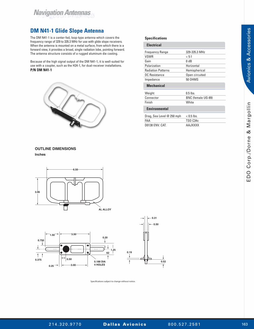
DM N41-1 Glide Slope AntennaThe DM N41-1 is a center-fed, loop-type antenna which covers the frequency range of 329 to 335.3 MHz for use with glide slope receivers. When the antenna is mounted on a metal surface, from which there is a forward view, it provides a broad, single radiation lobe, pointing forward. The antenna structure consists of a rugged aluminum die casting.
Because of the high signal output of the DM N41-1, it is well-suited for use with a coupler, such as the H24-1, for dual-receiver installations.P/N DM N41-1
Navigation AntennasNavigation Antennas
Electrical
Mechanical
Environmental
Specifications
Frequency Range 329-335.3 MHzVSWR < 5:1Gain 0 dBPolarization HorizontalRadiation Patterns HemisphericalDC Resistance Open circuitedImpedance 50 OHMS
Weight 0.5 lbs.Connector BNC (female UG-89)Finish White
Drag, Sea Level @ 250 mph < 0.5 lbs.FAA TSO C34cD0138 ENV. CAT. AAJXXXX

164
ED
O C
orp
./Do
rne
& M
arg
ollin
2 1 4 . 3 2 0 . 9 7 7 0 Dal las Av ion ics 8 0 0 . 5 2 7 . 2 5 8 1
Avio
nics &
Accesso
ries
OUTLINE DIMENSIONS
Inches
3.00±0.0
4.70±0.0
0.81 MAX
0.75 MAX
Specifications subject to change without notice.
3.30±0.0
CONNECTORTYPE TNC FEMALE
0.22 MOUNTINGHOLES 4 PLCSCSK FAR SIDE(100° x 0.385 DIA)
1.60±0.0
0.80
LABEL LOCATEDAPPROX ASSHOWN
0.140.14
1.65
(2.50) O-RINGGROOVE
FWD
DM N102-2 GPS AntennaThe DM N102-2 GPS antenna has been designed to meet ARINC 743A active antenna requirements and takes advantage of the latest in micro-strip and microcircuit technology.
An integral preamplifier/filter assembly provides 33 dB of gain. DC bias is provided through the RF Coaxial Connector.P/N DM N102-2
Specifications
Frequency 1575.42 MHzVSWR 2.0:1Polarization RHCPImpedance 50 OHMSAntenna Gain (Typical) 2 dBic @ zenithGain Coverage (minimum) -2.0 dBic 0° ≤ Ø ≤ 75° -3.0 dBic 75° ≤ Ø ≤ 80° -4.5 dBic 80° ≤ Ø ≤ 85° -7.5 dBic Ø = 90° (horizon)Gain (preamp) 33.0 ± 3 dBNoise Figure 2.0 dBPower Handling 1 WattVoltage +12VDCCurrent 100 mA maximumLightning Protection DC grounded
Connector TNCWeight 9 oz. (nominal)Finish (Radome) Skydrol-resistant, white valoxFinish (Base) Chemfilm MIL-C-5541Reference Documents ARINC 743A, D0-160c, D0-228, TSO C144
Electrical
Mechanical
Navigation AntennasNavigation Antennas

165
ED
O C
orp
./D
orn
e &
Ma
rgo
llin
2 1 4 . 3 2 0 . 9 7 7 0 Dal las Av ion ics 8 0 0 . 5 2 7 . 2 5 8 1
Avi
on
ics
& A
cces
sori
esDM NI24 & DM NI29 Series L-Band Blade AntennasThese L-Band blades utilize a new concept of antenna design and manufacture which makes them ideal for commercial as well as military application. The radiating element is encapsulated in an epoxy dielectric body by a transfer molding process. This simple design has several notable advantages:
• Moisture Proof—The antenna is impervious to moisture penetration either by direct immersion or by extended exposure to high-humidity conditions.• Rugged Design—The interlocked mounting base and radiating element, molded into the dielectric body, are a completely unified, integral, and rugged assembly.• Economy—The molding process is a high-production technique, substantially reducing antenna cost.
The antennas have been used with various equipment such as DME, IFF, TACAN, TELEMETRY, and BEACON. The DM NI29-15, DM NI29-19, and DM NI29-18, have been designed to provide ideal performance for various Flight-Fone Systems.P/N DM NI24P/N DM NI29
Notes:
1. DM NI24, has six No. 6 mounting holes (0.144 dia CSK 100 x 0.28 dia)
2. DM NI29 Series has four mounting holes (0.196 dia CSK 100 x 0.385 dia).
OUTLINE DIMENSIONS
Inches (Centimeters)
3.3 MAX(8.382)
3.75(9.525)2.0
(5.08)
1.130(2.8575)
1.75(4.445)
1.250(3175)
0.625(1.5875)
1.250(3.175)
3.250(8.255)
2.250(5.715)
4.500(11.43)5.25
(13.335)
FIGURE 1
0.980(2.49)
0.490(1.245)
1.800(4.572)
3.600(9.144)
FIGURE 2
Specifications subject to change without notice.
Mounting Hole Pattern
DM NI24 Series
DM NI29 Series
Navigation AntennasNavigation Antennas
Electrical
Mechanical
Specifications
Frequency Range 849 to 1220 MHzVSWR 0.85 to 0.90 (1.4:1) 0.90 to 1.10 (1.7:1) 1.10 to 1.22 (2.0:1)Gain Typically within 0.5 dB of a matched l/4 stubPolarization VerticalPower 100 Watts average 4.0 kW peak Radiation Patterns Similar to l/4 stub
Connector N (female)Weight 6 oz.Aero Drag 13 oz. sea level, Mach 0.5 30 oz. sea level, Mach 0.8 ARINC 532 D (ATC Transponder) 521 D (DME) FAA TSO-C66 (DME) TSO-C74 (ATC Transponder) ENV. CAT. ABAXXXXCL1Mounting Pattern NI24-15, Figure 1 NI24-19, Figure 1 NI29-18, Figure 2
166
ED
O C
orp
./Do
rne
& M
arg
ollin
2 1 4 . 3 2 0 . 9 7 7 0 Dal las Av ion ics 8 0 0 . 5 2 7 . 2 5 8 1
Avio
nics &
Accesso
ries
OUTLINE DIMENSIONSInches
COLOR CHART
-1-2-3-4-5-6
INTERNATIONAL ORANGEGLOSSY WHITELUSTERLESS WHITELUSTERLESS BLACKLUSTERLESS GREYGLOSSY RED
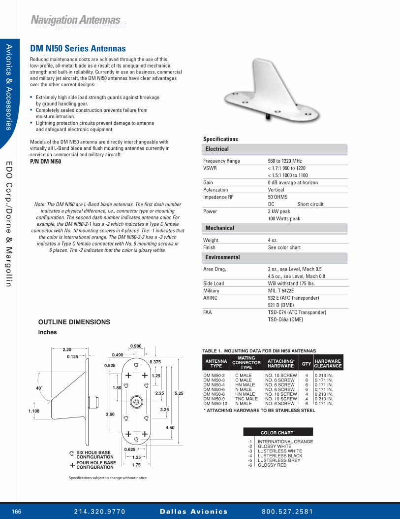
TABLE 1. MOUNTING DATA FOR DM NI50 ANTENNAS
ANTENNATYPE
MATING CONNECTOR
TYPEATTACHING*HARDWARE
DM NI50-2DM NI50-3DM NI50-4DM NI50-6DM NI50-8DM NI50-9DM NI50-10
C MALEC MALEHN MALEN MALEHN MALETNC MALEN MALE
NO. 10 SCREWNO. 6 SCREWNO. 6 SCREWNO. 6 SCREWNO. 10 SCREWNO. 10 SCREWNO. 6 SCREW
HARDWARECLEARANCEQTY
4666446
0.213 IN.0.171 IN.0.171 IN.0.171 IN.0.213 IN.0.213 IN.0.171 IN.
* ATTACHING HARDWARE TO BE STAINLESS STEEL
+ +
+ +
+SIX HOLE BASECONFIGURATIONFOUR HOLE BASECONFIGURATION
2.200.125
1.108
40˚
0.825
3.60
1.80
1.25
2.25
3.25
4.50
5.25
0.980
0.4900.375
0.6251.251.75
Specifications subject to change without notice.
DM NI50 Series AntennasReduced maintenance costs are achieved through the use of this low-profile, all-metal blade as a result of its unequalled mechanical strength and built-in reliability. Currently in use on business, commercial and military jet aircraft, the DM NI50 antennas have clear advantages over the other current designs:
• Extremely high side load strength guards against breakage by ground handling gear.• Completely sealed construction prevents failure from moisture intrusion.• Lightning protection circuits prevent damage to antenna and safeguard electronic equipment.
Models of the DM NI50 antenna are directly interchangeable with virtually all L-Band blade and flush mounting antennas currently in service on commercial and military aircraft.P/N DM NI50
Note: The DM NI50 are L-Band blade antennas. The first dash number indicates a physical difference, i.e., connector type or mounting
configuration. The second dash number indicates antenna color. For example, the DM NI50-2-1 has a -2 which indicates a Type C female
connector with No. 10 mounting screws in 4 places. The -1 indicates that the color is international orange. The DM NI50-3-2 has a -3 which
indicates a Type C female connector with No. 6 mounting screws in 6 places. The -2 indicates that the color is glossy white.
Navigation AntennasNavigation Antennas
Electrical
Mechanical
Environmental
Specifications
Frequency Range 960 to 1220 MHzVSWR < 1.7:1 960 to 1220 < 1.5:1 1000 to 1100 Gain 0 dB average at horizon Polarization VerticalImpedance RF 50 OHMS DC Short circuitPower 3 kW peak 100 Watts peak
Weight 4 oz.Finish See color chart
Areo Drag, 2 oz., sea Level, Mach 0.5 4.5 oz., sea Level, Mach 0.8 Side Load Will withstand 175 lbs. Military MIL-T-5422EARINC 532 E (ATC Transponder) 521 D (DME) FAA TSO-C74 (ATC Transponder) TSO-C66a (DME)

167
ED
O C
orp
./D
orn
e &
Ma
rgo
llin
2 1 4 . 3 2 0 . 9 7 7 0 Dal las Av ion ics 8 0 0 . 5 2 7 . 2 5 8 1
Avi
on
ics
& A
cces
sori
es
OUTLINE DIMENSIONS
Inches
DM NI52-25.625
4.250
2.812
1.3750.183
3.187
1.593
3.203
6.406
1.218
2.253
2.437
0.187 DIA THRU 0.332
DIA CSK x 100∞
FAR SIDE
TYPICAL ELEVATION OUTLINE
0.125
0.62 DIA
0.59
2.18
DM NI52-1
4.612
3.259
2.306
1.353
2.875
5.750
1.562
2.343
3.124
1.937
3.875
0.187 DIA THRU 0.332
DIA CSK x 100∞
FAR SIDE
0.781
Specifications subject to change without notice.
DM NI52 Series AntennasThe DM NI52 series are suitable for use with ATC, FACAN, DME, IFF and other systems requiring L-Band Operation.
Reduced maintenance costs are achieved through the use of this low profile, all metal blade as a result of its unequalled mechanical strength and built in reliability. Currently in use on business, commercial and military jet aircraft, the DM NI52 antenna has clear advantages over other current designs:
• Extremely high side load strength guards against breakage by ground handling gear.• Completely sealed construction prevents failure from moisture incursion.• Lightning protection circuits prevent damage to antenna and safeguard electronic equipment. P/N DM NI52
Navigation AntennasNavigation Antennas
Electrical
Mechanical
Specifications
Frequency 960 to 1,220 MHzVSWR < 1.7:1 960 to 1,220 < 1.5:1 1,000 to 1,100 Gain 0 dB average @ horizon Power 3 kW peakAverage 100 WattsImpedance RF 50 OHMSDC Short Circuit Polarization Vertical
Weight 6 oz.Aero Drag 2 oz., sea Level, Mach 0.5: 4.5 oz., sea Level, Mach 0.8: Side Load Will withstand 175 lbs.Military MIL-T-5422EARINC (ATC Transponder) 532D (DME) 521DFAA (ATC Transponder) TSO C74 (DME) TSO C66a

168
ED
O C
orp
./Do
rne
& M
arg
ollin
2 1 4 . 3 2 0 . 9 7 7 0 Dal las Av ion ics 8 0 0 . 5 2 7 . 2 5 8 1
Avio
nics &
Accesso
ries
OUTLINE DIMENSIONS
Inches
1.000
1.80
0.687 DIA
3.625
++
+
+
+4 "A" HOLESFOR NO. 8 SCREWS
0.500
0.82
MOUNTING HOLE PATTERNS
DM NI70-1DM NI70-2
1.250
3.250
4.500
0.625
1.250
0.875
0.144 DIA HOLE THRUCSK 100∞ X 0.28 DIATYP 6 PLACES
0.375
1.750
DM NI70-3
Specifications subject to change without notice.
2.20
5.25 1.75
40
CONNECTOR TYPE CFEMALE (-1, -3)
0.88
0.65
3.60
1.10
DM NI70 Series DME/ATC Transponder AntennasThe DM NI70 L-Band antennas offer more than sufficient bandwidth (950 to 1,220 MHz) for use with civil aviation ATC transponders and distance measuring equipment (DME). The antenna provides omnidirectional, vertically polarized coverage when installed on the top, or bottom, of an aircraft. Its streamlined shape assures minimum aerodynamic drag. Structurally, the antenna consists of a single metal element.P/N DM NI70
Navigation AntennasNavigation Antennas
Environmental
Mechanical
Electrical
Specifications
Frequency Range 950 to 1220 MHzVSWR < 1.7:1 950 to 1220 MHz < 1.5:1 1000 to 1100 MHz Gain Equivalent to a quarter wave stubPolarization VerticalPower 2 kW peakRadiation Patterns OmnidirectionalDC Resistance Open circuitedImpedance 50 OHMS
Weight 0.25 lbs.Connector C (female) DM NI70-1, DM NI70-3 BNC (female) DM NI70-2 Finish White
TSO C66a ENV. CAT. JAJXXXXTSO C74b ENV. CAT. JAJXXXX CAT. IIDrag, Sea Level @ 250 mph 0.5 lbs.

169
ED
O C
orp
./D
orn
e &
Ma
rgo
llin
2 1 4 . 3 2 0 . 9 7 7 0 Dal las Av ion ics 8 0 0 . 5 2 7 . 2 5 8 1
Avi
on
ics
& A
cces
sori
es
OUTLINE DIMENSIONSInches (Centimeters)
2.20(5.59)MAX
30∞REF
86∞REF
2.62(6.65)
1.61 REF(4.09)
0.150(0.381) 0.50
(1.27)
0.50 MIN(1.27)
0.70(1.78) DIA
FWD
1.53(3.89) DIA
0.980(2.489)
0.196(0.498)
CSK 100∞ x 0.3850.978 DIA
(4 PL FARSIDE)
O-RING
5.25(13.34)
1.34(3.40) DIA
1.800(4.572)
1.75(4.45)
3.600(9.144)
Specifications subject to change without notice.
DM 1601354 L-Band AntennaThe DM 1601354 L-Band Antenna has been designed for BCAS characteristics to provide more stringent radiation pattern directivity to assure reliable system performance.
Features of the DM NI50 series have still been retained to provide:• Extremely high side-load strength guards against breakage by ground handling gear • Completely sealed construction prevents failure from moisture incursion• Lightning protection circuits prevent damage to antenna and safeguards electronic equipmentP/N DM 1601354
Navigation AntennasNavigation Antennas
Electrical
Mechanical
Specifications
Frequency Range 960 to 1220 MHzVSWR 1.8:1 @ 960 to 1220 MHz 1.42:1 @ 1000 to 1100 MHzGain See belowImpedance 50 OHMSPolarization VerticalPower (CW) 250 W CWPower (Peak) 3 kWRadiation Pattern See below DC Resistance Short circuitModel No. DM 1601354Part No. DM 1601354-001 (Yellow) DM 1601354-002 (Orange)Boeing Part No. S22OT116-101
Connectors C (female)Weight 0.32 lbs. (0.15 Kg)
Radiation Pattern & GainThe radiation pattern is an adjusted omnidirectional pattern. It has some directivity in the forward direction to improve the gain in the most needed forward direction for ASAS, BCAS, and TCAS. This adjustment in pattern and in gain purposely improves the reception and transmission characteristics while still meeting the following ARINC characteristics:• 709-1 (DME)• 718 (ATC Transponder)• 730 (ASAS)
By making the radiation pattern slightly eccentric rather than perfectly omnidirectional, the forward gain approximates that of a vertically polarized quarter wave stub. The rearward gain is within 2.5 dB below the forward gain.

170
ED
O C
orp
./Do
rne
& M
arg
ollin
2 1 4 . 3 2 0 . 9 7 7 0 Dal las Av ion ics 8 0 0 . 5 2 7 . 2 5 8 1
Avio
nics &
Accesso
ries
OUTLINE DIMENSIONS
Inches (Centimeters)
DM PN19-2-1
0.25 R (6.4) 4 PL
0.224 DIA (5.68)C SINK 100 DEG 0.285 (7.23) DIA FARSIDE 4 PL
0.185 (4.7)
0.75 (19.1)
TNC FEMALE
SAFETYWIRE TAB
0.50 R (12.7)2 PL
1.375(34.92)
1.75(44.5)
3.65(92.7)
2.75(69.85)
3.52(89.4)
1.76(44.7)
2.90(73.5)
1.375(34.92)
DM PN19-1-1
"O" RING GROOVE 0.25 R(6.4) 4 PL
0.224 DIA (5.68)C SINK 100 DEG 0.285 (7.23) DIA FARSIDE 4 PL
0.185 (4.7)
TNC FEMALE
SAFETYWIRE TAB
0.50 R (12.7)2 PL
2.05(52.0)
1.375(34.92)
1.375(34.92)
1.76(44.7)
3.52(89.4)
2.75(69.85)
2.90(73.6)
1.300 (33.0)
4.12(104.6)
Specifications subject to change without notice.
DM PN19 Series Radio Altimeter AntennasThe DM PN19-1-1 and DM PN19-2-1 utilize micro-strip technology to provide an extremely low-profile antenna. This fully functional series was developed to be a high-quality, low-cost, lightweight, and near conformal antenna. The dielectric insert and radiating elements are recessed into a complete four-sided metal housing. This exclusive design feature protects the dielectric surface from the air stream for increased erosion protection in addition to preventing water intrusion and delamination.P/N DM PN19
Navigation AntennasNavigation Antennas
Mechanical
Electrical
Specifications
Frequency 4,200 to 4,400 MHzVSWR < 2.0:1 4,200 to 4,400 MHz maximum < 1.8:1 4,275 to 4,325 MHz maximumPolarization LinearGain 10 dBImpedance 50 OHMS
Weight 5 oz. maximumConnectors TNC (female)Dimensions See drawingTemperature -55°C to +85°C operatingAltitude -1,000’ to +70,000’Lightning Protection DC ShortVibration 10 G'sApprovals FAA TSO C87, ARINC 707/552 DO160C...E1-ABC¢XWHDNSXXXXXXXXXX MIL-E-5400

171
ED
O C
orp
./D
orn
e &
Ma
rgo
llin
2 1 4 . 3 2 0 . 9 7 7 0 Dal las Av ion ics 8 0 0 . 5 2 7 . 2 5 8 1
Avi
on
ics
& A
cces
sori
es
TABLE 1. MOUNTING DATA
ANTENNA
TYPE
MATING
CONNECTOR
TYPE
DM NI 7
DM NI 7-2
DM NI 7-8
DM NI 7-9
C MALE
HN MALE
HN MALE
C MALE
71.50 R
20.00 R
71.50 R
71.50 R
RADIUS OF
BASE
OUTLINE DIMENSIONS
Inches
MOUNTING HOLE
PATTERN
FORWARD
TYPE C
CONN
1.30
2.17
0.189 DIA
12 HOLES EQUALLY SPACED
6.36
DIA
8.950 MAX
DIA
Specifications subject to change without notice.
NOTE: FOR CONTOUR OF
BASE SEE TABLE 1
DM NI7 Series L-Band Flush AntennasThe DM NI7 series of L-Band annular slot antennas is the result of 20-years of continuous experience in the design and production of this type of antenna.
Smaller Aperture—provides more signal at angles near the horizon; regardless of aircraft attitude.
Moisture Proofing—ensures that DM NI7 antennas will not fail because of the condensation which is inevitable with aircraft. Each unit is sealed and plastic foam-filled. All materials have been carefully selected and isolated to prevent galvanic corrosion.
Cabin Pressurization—is not jeopardized. The DM NI 7 antennas will successfully withstand 25 psi when suitably gasketed. Their rugged construction ensures that they will not be adversely affected by the most severe vibrations encountered in flight.P/N DM N17
Navigation AntennasNavigation Antennas
Immersion tested toAT-720/A only
Electrical
Mechanical
Specifications
Frequency Range 960 to 1220 MHzVSWR 1.5:1 960 to 1220 MHz 1.4:1 1030 to 1090 MHz Impedance 50 OHMSPolarization Vertical
Weight 21 oz.Connector See table 1Corrosion Resistance Impervious to Skydrol hydraulic fluid or other normal corrosive aircraft fluids.ARINC 532 D (ATC Transponder) 521 D (DME) Military MIL-E-5400 MIL-T-5422C MIL-E-5272A MIL-A-256612FAA TSO-C74 (ATC transponder ) TSO-C66 (DME)

220
ED
O C
orp
./Do
rne
& M
arg
ollin
2 1 4 . 3 2 0 . 9 7 7 0 Dal las Av ion ics 8 0 0 . 5 2 7 . 2 5 8 1
Avio
nics &
Accesso
ries
OUTLINE DIMENSIONS
Inches
ANTENNA
REMOTEARMOFFON
3.07 REF
3.36
4.754.187
3.50 REF
7.65 REF
6.90 REF
3.254.505.568.75 REF
0.500.50 REF0.28
0.218+0.005 DIA -0.0156 PL
Specifications subject to change without notice.
DM ELT 14-1-1 Emergency Locator TransmitterThe DM ELT 14-1-1 emergency locator transmitter is approved to FAA TSO-C91a for automatic fixed (AF) equipment. The DM U237-1-1 adapter plate is furnished with the ELT to allow easy upgrade from our DM ELT 8 and DM ELT 6-series ELT's, as well as competitor's models.
The DM U231 series remote control/indicators allow the operator to manually turn the transmitter on for test or emergency landing purposes, RESET the transmitter and place the transmitter in the normal “Armed” mode.P/N DM ELT 14-1-1
ELT’sELT’s
Accessories
P/N DM ELT 14-1-1 Emergency locator transmitter, with DM U158-1 and DM U237-1-1P/N DM ELT 14-2-1 Emergency locator transmitter without DM U158-1 or DM U237-1-1P/N DM U231-1 Remote control/indicator, surface mountedP/N DM U231-2 Remote control/indicator, panel mounted P/N DM U242-1 Cable kit for DM U231-series (15' length)P/N DM ELT 14.2 ELT antenna, flexible, for use with DM ELT 14 transmitterP/N DM ELT 14.3 Coaxial cable for DM ELT 14.2 (46" length)P/N DM ELT 14.4 Coaxial cable for DM ELT 14.2 (79" length)P/N DM Q18-1/A ELT antenna, rigid (250 MPH rated), three-hole mountP/N DM Q18-3 ELT antenna, rigid (400 MPH rated), 4-hole mountP/N DM U60-1 Coaxial cable for DM Q18-series (50" length)P/N DM U60-2 Coaxial cable for DM Q18-series (120" length)P/N DM U158-1 Alkaline battery pack for DM ELT 14-1-1P/N DM U258-1 Power cell for DM U231-1P/N DM U264-1 Power cell for DM U231-2 P/N DM U237-1-1 Adapter plate for DM ELT 14-1-1; Retrofit for DM ELT 8.1, DM ELT 6.1, and competitor's ELT'S
2 1 4 . 3 2 0 . 9 7 7 0 Dal las Av ion ics 8 0 0 . 5 2 7 . 2 5 8 1220
Electrical
Mechanical
Specifications
Frequency Range 121.5/243.0 MHzPeak Effective Radiated Power 50 mW for 50-hrs.Power Supply DM U158-1 replaceable alkaline battery packModulation Audio downward swept tone Characteristics Range > 700 Hz between 1600-300 Hz maximumBandwidth 25 KHzFlight Deck—Remote Visual alert & control switch
Operating Temperature Range -20°C to +55°CStorage Temperature Range -55°C to +85°CAltitude 55,000’G-switch Activation 3 fps £ Δ V £ 4 fpsWeight 4.5 lbs. (2.0 Kg) maximumAntenna(s) See accessories listRemote Control/Indicator See accessories list