VHF Bp-Br Repeater Duplexers
23
1 VHF Bp-Br Repeater Duplexers DB-4062 Duplexer This article was written to provide amateur radio repeater owners, builders, and installers with information about duplexers that is not usually found in handbooks. This article requires that you have an advanced understanding of how antennas, receivers, transmitters work and a knowledge of electronic test instruments. Duplexers not only allow repeaters to use a “single” antenna, they also play a major role in the installations performance. The majority of radio repeaters used by amateurs operate at VHF frequencies. The frequency spacing between the transmitter and receiver is only 600 kHz in this band. Because of this close frequency spacing, a duplexer must use bandpass/band-reject (Bp-Br) cavities to provide enough noise suppression between the repeaters transmitter and receiver. Contents 1. Test Equipment Used 2. Selecting a Bp-Br Duplexer 3. Measuring Transmitter Noise. 4. Calculating Minimum Duplexer Isolation 5. Adjacent-Channel Rejection Ratio (ACCR) 6. Bp-Br Cavity Design and How They Work 7. Receiver Desensitization Test 8. Cavity Cable Length and Type 9. Repairing and Tuning Duplexers 10. Installing Duplexers Test Equipment Used Thunderbolt GPS Frequency Standard Keysight N9340B Spectrum Analyzer with Tracking Generator Option KC901S Vector Network Analyzer
Transcript of VHF Bp-Br Repeater Duplexers
1
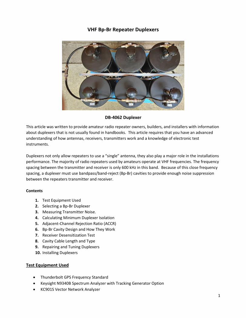
VHF Bp-Br Repeater Duplexers
DB-4062 Duplexer
This article was written to provide amateur radio repeater owners, builders, and installers with information
about duplexers that is not usually found in handbooks. This article requires that you have an advanced
understanding of how antennas, receivers, transmitters work and a knowledge of electronic test
instruments.
Duplexers not only allow repeaters to use a “single” antenna, they also play a major role in the installations
performance. The majority of radio repeaters used by amateurs operate at VHF frequencies. The frequency
spacing between the transmitter and receiver is only 600 kHz in this band. Because of this close frequency
spacing, a duplexer must use bandpass/band-reject (Bp-Br) cavities to provide enough noise suppression
between the repeaters transmitter and receiver.
Contents
1. Test Equipment Used
2. Selecting a Bp-Br Duplexer
3. Measuring Transmitter Noise.
4. Calculating Minimum Duplexer Isolation
5. Adjacent-Channel Rejection Ratio (ACCR)
6. Bp-Br Cavity Design and How They Work
7. Receiver Desensitization Test
8. Cavity Cable Length and Type
9. Repairing and Tuning Duplexers
10. Installing Duplexers
Test Equipment Used
Thunderbolt GPS Frequency Standard
Keysight N9340B Spectrum Analyzer with Tracking Generator Option
KC901S Vector Network Analyzer
2
40 dB Attenuator (500W)
Texscan RA-54 50 dB Step Attenuator
50 ohm N Type Termination (2)
Decibel Products DB-4062 Duplexer
Bird 43 Power Meter
Welz CT-150 50 Ohm Load (150W)
HP 8753C Network Analyzer
Selecting a Bp-Br Duplexer
Duplexers are expensive, so it’s very important that the duplexer you purchase provides the proper amount
of isolation between the repeaters transmitter and receiver. Repeater manufacturers will suggest the type
of duplexer needed for their repeater and usually offer to sell you one. If you are building the repeater
from scratch, you’ll need to figure out the type of duplexer that is needed. All transmitters create RF noise
on each side of the carrier frequency (See example below). You might see this RF noise identified as
spectral regrowth, phase-noise or white noise, but most duplexer manuals just refer to it as “transmitter
noise”. Because the RF noise occurs at the same frequency as the repeaters receiver, the duplexer must
suppress this noise to a level that’s below the receivers input sensitivity level. If this noise is not isolated
from the repeaters receiver, it will “desense” the receiver’s sensitivity and cause a weak signal problem.
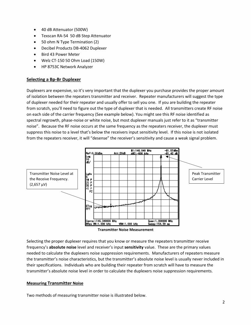
Transmitter Noise Measurement
Selecting the proper duplexer requires that you know or measure the repeaters transmitter receive
frequency’s absolute noise level and receiver’s input sensitivity value. These are the primary values
needed to calculate the duplexers noise suppression requirements. Manufacturers of repeaters measure
the transmitter’s noise characteristics, but the transmitter’s absolute noise level is usually never included in
their specifications. Individuals who are building their repeater from scratch will have to measure the
transmitter’s absolute noise level in order to calculate the duplexers noise suppression requirements.
Measuring Transmitter Noise
Two methods of measuring transmitter noise is illustrated below.
Peak Transmitter
Carrier Level
Transmitter Noise Level at
the Receive Frequency.
(2,657 µV)

3
Method 1: Demonstrates the transmitter noise measurement results of a Bridgecom BCR-50-DV repeater.
Method 2: Demonstrates the transmitter noise measurement of a 146.04/64 repeater.
Method 1
The transmitter noise measurement was used to determine the difference between carrier level and noise
level at the 600 kHz receive frequency. In this case, the value was 75.18 dB. The power meter reading was
50W (+46.99 dBm) at the repeater transmit carrier frequency. Subtracting the 75.18 by 46.99 = -28.19 dBm
which equals the absolute noise level. Note: The noise test must be made at the same output power level
the repeater will be operating at. Ensure the spectrum analyzers dynamic level is great enough that the
600 kHz offset frequency does not reach the analyzers noise floor. Just looking at the spectrum analyzers
screen, one might assume that this RF noise level would not be a problem, but -28.19 dBm equals to a
signal level of 8,901 µV which would destroy the receivers 0.2 µV input sensitivity.
Method 2
RF INPUT
TX
TRACKING
POWER METER
N9340B
40 dB 500W
GEN. OUT
REPEATER
RX
100 kHz - 3.0 GHz
VARIABLE STEP
ATTENUATOR
HANDHELD SPECTRUM ANALYZER
ATTENUATOR
Agilent Technologies
Spectrum Analyzer Settings
1. The repeater frequency of 146.30/90 was used for this example, so the SA center frequency was 146.6 and with a Span of 1 MHz.
2. Resolution and Video bandwidth is 10kHz 3. Detector set Peak Positive 4. Marker set carrier frequency and Delta 600 kHz 5. Trace set to Max Hold and Averaging 5 6. Signal is applied to SA and step attenuator is
adjusted so carrier is at the 0.0 dBm Ref. line.

4
This test allows you to use a standard 50 Ω load, but requires you to modify a Tee connector so the
spectrum analyzer is not destroyed. Tee Connector Modification: Remove the connector center pin and
break off the fingers and replace the center pin. The connector modification provides 40 to 50 dB of
attenuation across a frequency of 144 – 148 MHz.
The delta between the 146.04/64 was 81.57 dB at a transmitter output power of 45W (46.5 dBm), so the
absolute noise level is -35.07 dBm (-81.57 dB – 46.5 dBm = -35.07 dBm).
Calculating Minimum Duplexer Isolation
ATTENUATOR
TEE CONNECTOR
GEN. OUT
Agilent TechnologiesN9340B
TRACKING
HANDHELD SPECTRUM ANALYZER
RX
POWER METER
MODIFIED
TX
50 OHM LOAD
RF INPUT
REPEATER
20 dB STEP
100 kHz - 3.0 GHz
100 W

5
Most duplexer calculations only include the receiver sensitivity and the transmitter absolute noise level, but
I’ve also added the duplexer’s antenna Tee connector and receive cavity insertion loss to the duplexer
calculation. When the transmitter’s receive frequency noise passes through the duplexer’s antenna Tee
connector, the antenna absorbs about 3 dB of the noise and the receive cavities absorb another 2 dB due to
insertion loss.
Never select a duplexer that just makes the minimum calculated suppression number. Duplexers are tuned
with all the ports terminated with 50 ohms, but it’s seldom that the repeater’s receiver, transmitter and
antenna will all have an impedance of 50 ohms. Any impedance connected to the duplexer that is not 50
ohms can detune the duplexer. Duplexer internal components can oxidize over time thereby causing the
duplexer to deviate from the original specs. Temperature can also change the duplexer’s alignment if it’s
not located in a controlled environment. To compensate for all of these effects, always add 10 dB to the
calculated minimum number, which means you would need to acquire a duplexer with 97.55 dB of isolation
for the Bridgecom repeater and 87.43 for the 146.04/64 repeater. The maximum isolation for a 4 cavity
duplexer is about 90 dB and a 6 cavity duplexers can provide more than 100 dB, so the Bridgecom repeater
would require a 6 cavity duplexer.
Adjacent-Channel Rejection Ratio (ACRR)
If you’re wondering why only the repeaters transmitter’s absolute noise is considered during the duplexer
minimum suppression calculation, it’s because that most of the transmitter’s RF energy is radiated by the
antenna. Any amount of the transmitter’s RF energy that is not radiated by the antenna is easily
suppressed by the receive cavities. All receiver’s normally have a degree of rejection to out of band
frequencies. The ACRR test is a measurement ratio in (dB) between a receivers’ input sensitivity against a
similar signal on another frequency. I occasionally use this test on amateur radio receivers to determine at
what transmit frequency level receiver desensitization occurs.
Below is an ACRR measurement of a Yaesu FTM-3100 transceiver for an offset of 600 kHz: RX input
sensitivity was -121 dBm (0.2 µV) and -38 dBm (2,820 µV) was required to detect a noise level change. The
ACRR specification is 83 dB (121 -38 = 83). Note: The Selectivity specification for this transceiver is 60 dB @
28 kHz. Due to a receivers inherit suppression of the transmitters frequency and the minimal amount of
suppression needed by the receive cavities, some repeater owners will replace one receive Bp-Br cavity
with a band-pass (Bp) cavity which provides more rejection to out-of-band signals.
T
COUPLER
R
SWEEP GENERATOR-100 dBM to +10 dBm
SIGNAL SIGNAL
Inter fer ance Level
GENERATOR-130 dBM to -20 dBm
Set to RX Sensitivity Level
CTCSS
REPEATER

6
Bp-Br Cavity Design and How They Work
How the cavity Tee connector port reacts to impedance holds the secret of how Bp-Br cavities work. In this
case, the cavity pass frequency was adjusted to 146.90 MHz and the reject frequency to 146.30 MHz.
Figure 1 shows that with the bandpass adjustable resonator element adjusted to 146.90 MHz, it acts like a
parallel resonant circuit which produces a high impedance (415.2 ohms) at the cavity Tee port. This causes
the 146.90 MHz frequency to pass thru the Tee connector with only 0.65 dB of insertion loss.
Figure 2 show when the loop capacitor is adjusted to 146.30 MHz, the loop inductance and capacitor form a
series resonant circuit and provides a low impedance (5.3 ohms) path to ground for the 146.30 MHz
frequency. Figure 1 Figure 2
CouplingLoop
Bandpass Tuning Knob
Notch TuningCapacitor
AdjustableResonatorElement
CavityBody
"T" Connector
FixedResonator
146.90 MHz0 dBm
415 Ohms
-0.65 dBm146.90 MHz
-0.35 dBm
146.90 MHz
0 dBm146.30 MHz146.30 MHz
5.3 Ohms
-31 dBm
146.30 MHz
7
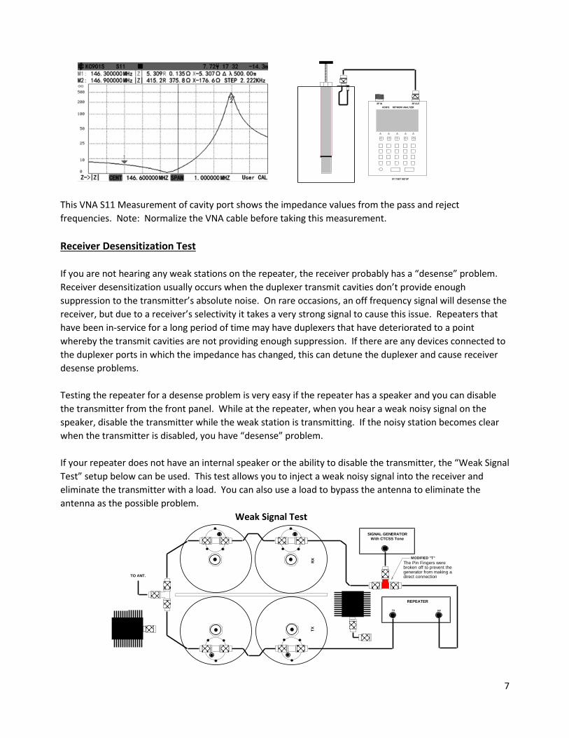
This VNA S11 Measurement of cavity port shows the impedance values from the pass and reject
frequencies. Note: Normalize the VNA cable before taking this measurement.
Receiver Desensitization Test
If you are not hearing any weak stations on the repeater, the receiver probably has a “desense” problem.
Receiver desensitization usually occurs when the duplexer transmit cavities don’t provide enough
suppression to the transmitter’s absolute noise. On rare occasions, an off frequency signal will desense the
receiver, but due to a receiver’s selectivity it takes a very strong signal to cause this issue. Repeaters that
have been in-service for a long period of time may have duplexers that have deteriorated to a point
whereby the transmit cavities are not providing enough suppression. If there are any devices connected to
the duplexer ports in which the impedance has changed, this can detune the duplexer and cause receiver
desense problems.
Testing the repeater for a desense problem is very easy if the repeater has a speaker and you can disable
the transmitter from the front panel. While at the repeater, when you hear a weak noisy signal on the
speaker, disable the transmitter while the weak station is transmitting. If the noisy station becomes clear
when the transmitter is disabled, you have “desense” problem.
If your repeater does not have an internal speaker or the ability to disable the transmitter, the “Weak Signal
Test” setup below can be used. This test allows you to inject a weak noisy signal into the receiver and
eliminate the transmitter with a load. You can also use a load to bypass the antenna to eliminate the
antenna as the possible problem.
Weak Signal Test
RF OUTRF IN
S11 TEST SETUP
KC901S NETWORK ANALYZER
TO ANT.
RX
REPEATER
TX
The Pin Fingers werebroken off to prevent thegenerator from making adirect connection
SIGNAL GENERATOR
TX
RX MODIFIED "T"
With CTCSS Tone

8
Cavity Cable lengths and Type
Some documents I’ve read claim that the cable length does not have any effect on the cavity rejection
performance, but my testing has verified otherwise when checking Bp-Br duplexers manufactured by
Decibel Products and Wacom.
For Bp-Br cavities, those ¼ λ cables between the between the duplexer cavities are not there for
impedance matching. The purpose of the ¼ λ cables is to transform the low impedance of the series
resonant notch circuit to a high impedance which is seen by the next cavity. This actually makes the next
cavities’ suppression more effective because its series resonant circuit is more efficient with a higher
impedance. It’s not uncommon to have individual cavities that have a notch suppression of 35 dB, but
when a 2 cavity duplexer is assembled, it measures 80 dB on each side. The ¼ λ cables on each side of the
antenna Tee connector are not for impedance matching either, but to present a high impedance between
the TX and RX frequencies which isolates one side from the other.
The following is an example of how the cavity inter-connecting cables can affect the total rejection value.
Using a 4 cavity DB-4060 duplexer, the two low-pass cavities were individually tested for rejection, then
tested coupled with the connecting cables.
Each Cavity Rejection -36.2 dB @ 146.92 MHz Both Cavities connected with a 10.5 inch Cable
The 2 individually tested had identical rejection values of 36.2 dB, which equals to a total 72.4 dB, but
connecting the 2 cavities together resulted in rejection value 78.75 dB. The 10.5 inch interconnecting cable
increased the rejection by 6.35 dB.
RX
Bp-Br Filter
RF IN RF OUT
Bp-Br Filter
KC901S NETWORK ANALYZERBp-Br Filter
TX
Bp-Br Filter
LOW PASS
HIGH PASS
Bp-Br Filter
TXHIGH PASS
RF OUT
RX
KC901S NETWORK ANALYZER
RF IN
Bp-Br Filter Bp-Br Filter
LOW PASS
Bp-Br Filter
9
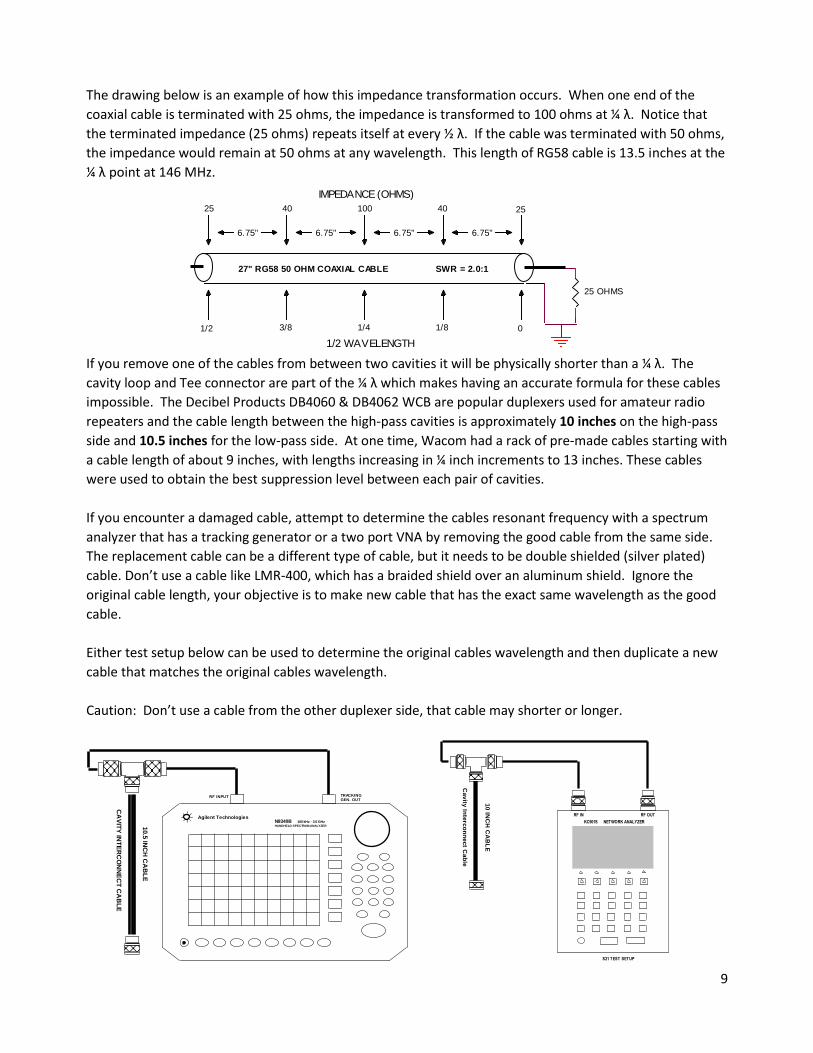
The drawing below is an example of how this impedance transformation occurs. When one end of the
coaxial cable is terminated with 25 ohms, the impedance is transformed to 100 ohms at ¼ λ. Notice that
the terminated impedance (25 ohms) repeats itself at every ½ λ. If the cable was terminated with 50 ohms,
the impedance would remain at 50 ohms at any wavelength. This length of RG58 cable is 13.5 inches at the
¼ λ point at 146 MHz.
If you remove one of the cables from between two cavities it will be physically shorter than a ¼ λ. The
cavity loop and Tee connector are part of the ¼ λ which makes having an accurate formula for these cables
impossible. The Decibel Products DB4060 & DB4062 WCB are popular duplexers used for amateur radio
repeaters and the cable length between the high-pass cavities is approximately 10 inches on the high-pass
side and 10.5 inches for the low-pass side. At one time, Wacom had a rack of pre-made cables starting with
a cable length of about 9 inches, with lengths increasing in ¼ inch increments to 13 inches. These cables
were used to obtain the best suppression level between each pair of cavities.
If you encounter a damaged cable, attempt to determine the cables resonant frequency with a spectrum
analyzer that has a tracking generator or a two port VNA by removing the good cable from the same side.
The replacement cable can be a different type of cable, but it needs to be double shielded (silver plated)
cable. Don’t use a cable like LMR-400, which has a braided shield over an aluminum shield. Ignore the
original cable length, your objective is to make new cable that has the exact same wavelength as the good
cable.
Either test setup below can be used to determine the original cables wavelength and then duplicate a new
cable that matches the original cables wavelength.
Caution: Don’t use a cable from the other duplexer side, that cable may shorter or longer.
1/8
1/2 WAVELENGTH
25
3/8
27" RG58 50 OHM COAXIAL CABLE
40
6.75"
0
40
1/41/2
SWR = 2.0:1
25 OHMS
IMPEDANCE (OHMS)
6.75"6.75"6.75"
25100
CA
VIT
Y IN
TE
RC
ON
NE
CT
CA
BL
E
10.5
INC
H C
AB
LE
100 kHz - 3.0 GHz
TRACKINGRF INPUT
N9340BHANDHELD SPECTRUM ANALYZER
GEN. OUT
Agilent TechnologiesRF OUT
10
INC
H C
AB
LE
Ca
vity
Inte
rco
nn
ec
t Ca
ble
RF IN
KC901S NETWORK ANALYZER
S21 TEST SETUP
10
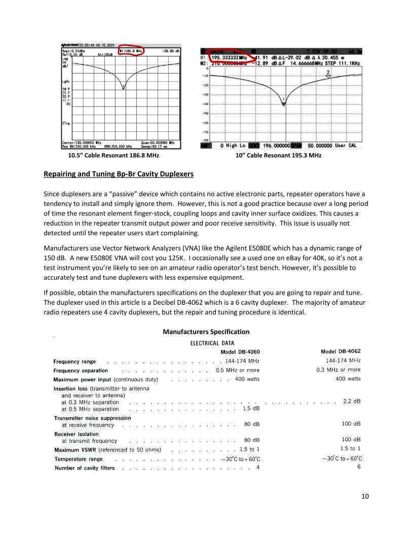
10.5” Cable Resonant 186.8 MHz 10” Cable Resonant 195.3 MHz
Repairing and Tuning Bp-Br Cavity Duplexers
Since duplexers are a “passive” device which contains no active electronic parts, repeater operators have a
tendency to install and simply ignore them. However, this is not a good practice because over a long period
of time the resonant element finger-stock, coupling loops and cavity inner surface oxidizes. This causes a
reduction in the repeater transmit output power and poor receive sensitivity. This issue is usually not
detected until the repeater users start complaining.
Manufacturers use Vector Network Analyzers (VNA) like the Agilent E5080E which has a dynamic range of
150 dB. A new E5080E VNA will cost you 125K. I occasionally see a used one on eBay for 40K, so it’s not a
test instrument you’re likely to see on an amateur radio operator’s test bench. However, it’s possible to
accurately test and tune duplexers with less expensive equipment.
If possible, obtain the manufacturers specifications on the duplexer that you are going to repair and tune.
The duplexer used in this article is a Decibel DB-4062 which is a 6 cavity duplexer. The majority of amateur
radio repeaters use 4 cavity duplexers, but the repair and tuning procedure is identical.
Manufacturers Specification
11
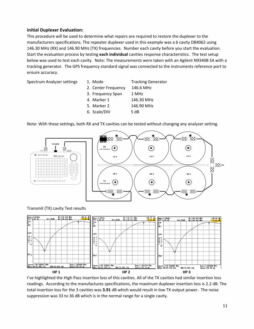
Initial Duplexer Evaluation: This procedure will be used to determine what repairs are required to restore the duplexer to the
manufacturers specifications. The repeater duplexer used in this example was a 6 cavity DB4062 using
146.30 MHz (RX) and 146.90 MHz (TX) frequencies. Number each cavity before you start the evaluation.
Start the evaluation process by testing each individual cavities response characteristics. The test setup
below was used to test each cavity. Note: The measurements were taken with an Agilent N9340B SA with a
tracking generator. The GPS frequency standard signal was connected to the instruments reference port to
ensure accuracy.
Spectrum Analyzer settings 1. Mode Tracking Generator
2. Center Frequency 146.6 MHz
3. Frequency Span 1 MHz
4. Marker 1 146.30 MHz
5. Marker 2 146.90 MHz
6. Scale/DIV 5 dB
Note: With these settings, both RX and TX cavities can be tested without changing any analyzer setting.
Transmit (TX) cavity Test results
HP 1 HP 2 HP 3
I’ve highlighted the High Pass insertion loss of this cavities. All of the TX cavities had similar insertion loss
readings. According to the manufactures specifications, the maximum duplexer insertion loss is 2.2 dB. The
total insertion loss for the 3 cavities was 3.91 dB which would result in low TX output power. The noise
suppression was 33 to 36 dB which is in the normal range for a single cavity.
GEN. OUT
LP 2
LOW PASS/146.02
LP 3
HP 3
N9340BAgilent Technologies
100 kHz - 3.0 GHz
RF INPUT TRACKING
HP 2
HIGH PASS/146.92
LP 1HANDHELD SPECTRUM ANALYZER
TO GPS
HP 1
RX
TX

12
Low Pass receive (RX) cavity test results.
LP 1 LP 2 LP 3
I’ve highlighted the Low Pass insertion loss which equaled to 1.9 dB. The RX insertion values were within
the manufactures specifications. The TX cavities have a major problem, but RX duplexer cavities tested ok.
Since the duplexer has been in service for over 20 years (8/2000), all of the cavities will need to be
refurbished.
Restoration Process: Solving insertion loss problems requires that the cavity bottom cover to be removed so you can clean the
resonator adjustable plunger. DB4062 cavity bottom covers are attached to the cavity with 4 rivets that
must be drilled out. Apparently Decibel didn’t use a template to drill these holes, so it’s important to mark
one of the holes before removal to save time later during reassembly. Once the bottom cover is removed,
turn the resonant adjustment knob screw all the way down until the resonator protrudes out of the cavity.
See photos below:
After the resonator plunger is extended as far as possible, clean and polish the plunger area just below the
finger-stock. CAUTION: Be careful not to damage the finger-stock. I prefer to use a metal polish called
“NEVER-DULL”, which can be purchased from Lowes to clean the plunger surface. Clean the polish residue
off with isopropyl alcohol. Once cleaned, adjust the plunger through the finger-stock several times and
then repeat the cleaning process again. Use the same cleaning procedure on all of the duplexer cavities.
The bottom covers were reinstalled using 8-32 x ¼ Stainless Steel screws and nuts.
The next task is to clean and polish the cavity coupling loops seen on the next page. The loop assembly can
be removed from the cavity top by removing 8 screws. The condition of the loop and variable capacitor
controls the amount of transmitter noise suppression and receiver isolation. These suppression and
isolation values are sometimes referred to as the “Notch” value in some specifications.
13
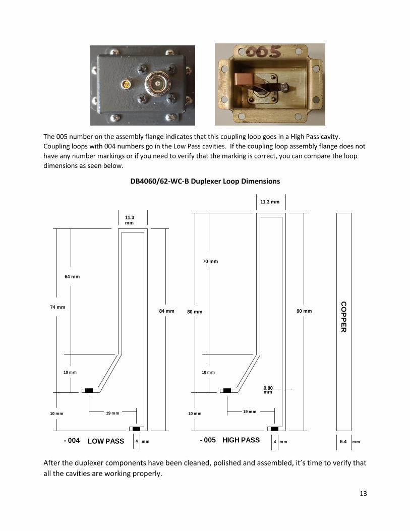
The 005 number on the assembly flange indicates that this coupling loop goes in a High Pass cavity.
Coupling loops with 004 numbers go in the Low Pass cavities. If the coupling loop assembly flange does not
have any number markings or if you need to verify that the marking is correct, you can compare the loop
dimensions as seen below.
DB4060/62-WC-B Duplexer Loop Dimensions
After the duplexer components have been cleaned, polished and assembled, it’s time to verify that
all the cavities are working properly.
HIGH PASS4
11.3mm
- 005
90 mm
4LOW PASS
19 mm
74 mm
19 mm
6.4
10 mm
mm
0.80
10 mm
CO
PP
ER
70 mm
10 mm
11.3 mm
- 004 mm
80 mm
mm
84 mm
mm
10 mm
64 mm
14
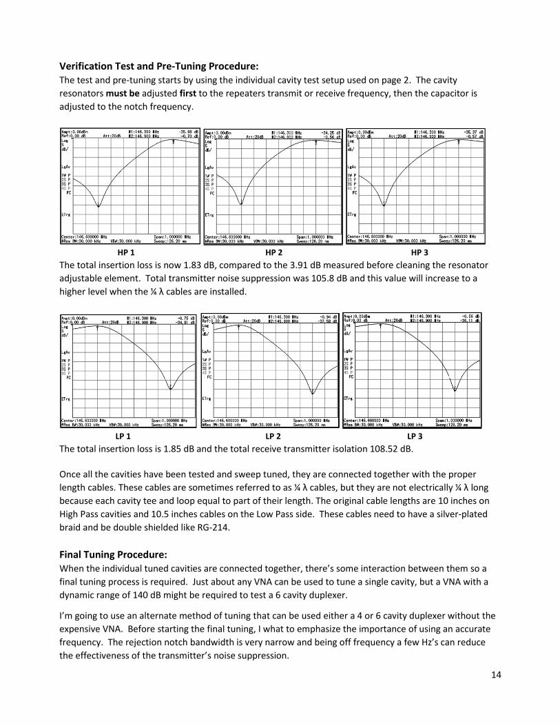
Verification Test and Pre-Tuning Procedure: The test and pre-tuning starts by using the individual cavity test setup used on page 2. The cavity
resonators must be adjusted first to the repeaters transmit or receive frequency, then the capacitor is
adjusted to the notch frequency.
HP 1 HP 2 HP 3
The total insertion loss is now 1.83 dB, compared to the 3.91 dB measured before cleaning the resonator
adjustable element. Total transmitter noise suppression was 105.8 dB and this value will increase to a
higher level when the ¼ λ cables are installed.
LP 1 LP 2 LP 3
The total insertion loss is 1.85 dB and the total receive transmitter isolation 108.52 dB.
Once all the cavities have been tested and sweep tuned, they are connected together with the proper
length cables. These cables are sometimes referred to as ¼ λ cables, but they are not electrically ¼ λ long
because each cavity tee and loop equal to part of their length. The original cable lengths are 10 inches on
High Pass cavities and 10.5 inches cables on the Low Pass side. These cables need to have a silver-plated
braid and be double shielded like RG-214.
Final Tuning Procedure: When the individual tuned cavities are connected together, there’s some interaction between them so a
final tuning process is required. Just about any VNA can be used to tune a single cavity, but a VNA with a
dynamic range of 140 dB might be required to test a 6 cavity duplexer.
I’m going to use an alternate method of tuning that can be used either a 4 or 6 cavity duplexer without the
expensive VNA. Before starting the final tuning, I what to emphasize the importance of using an accurate
frequency. The rejection notch bandwidth is very narrow and being off frequency a few Hz’s can reduce
the effectiveness of the transmitter’s noise suppression.

15
The 6 cavity duplexer is the most challenging to tune. Using the test setups below, the VNA’s VSWR test
mode is used to adjust the TX High Pass and RX Low Pass resonator knobs for the best readings a
146.90/146.30 MHz.
If the duplexers were properly designed, VSWR will usually provide the best RX and TX insertion Loss. Use
the next test to measure the insertion loss to verify this is true. If you change any of the resonator settings,
check the VSWR again to make sure it’s within the manufacturer’s 1.5:1 spec.
TX
LO
W P
AS
S
RF IN RF OUT
KC901S NETWORK ANALYZER
RX
HIG
H P
AS
S
KC901S NETWORK ANALYZER
RX
HIG
H P
AS
SLO
W P
AS
S
RF OUT
TX
RF IN

16
TX cavity sweep test setup
Spectrum Analyzer Settings
1. Mode Tracking Generator
2. Center Frequency 146.90 MHz
3. Frequency Span 2 MHz
4. Scale/DIV 1 dB
5. Maker 1 146.90 MHz
TX cavity sweep test setup
GEN. OUT
LP 1 LP 2
HP 3
TRACKING
HIGH PASS/146.92
TX
HANDHELD SPECTRUM ANALYZER
Agilent Technologies100 kHz - 3.0 GHz
RF INPUT
N9340B
HP 2
TO GPS
LOW PASS/146.02
LP 3
HP 1
RX
LP 1
GEN. OUT
TXHIGH PASS/146.92
N9340B
TO GPS
LP 2HANDHELD SPECTRUM ANALYZER
HP 1 HP 3
LOW PASS/146.02
RX
LP 3Agilent Technologies
HP 2
TRACKING
100 kHz - 3.0 GHz
RF INPUT
17
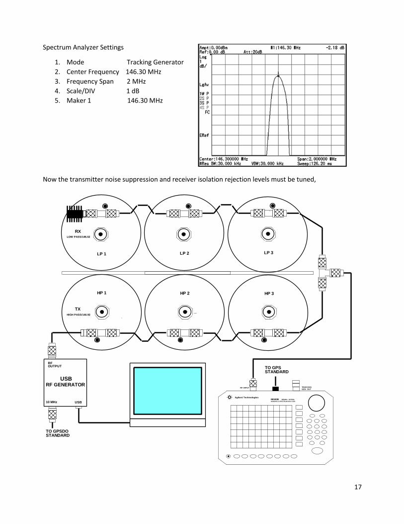
Spectrum Analyzer Settings
1. Mode Tracking Generator
2. Center Frequency 146.30 MHz
3. Frequency Span 2 MHz
4. Scale/DIV 1 dB
5. Maker 1 146.30 MHz
Now the transmitter noise suppression and receiver isolation rejection levels must be tuned,
10 MHz
LP 1
RX
HP 3
LP 2
TRACKING
RFOUTPUT
TX
HANDHELD SPECTRUM ANALYZER
Agilent Technologies
RF INPUT
USB
100 kHz - 3.0 GHz
TO GPSDO STANDARD
HIGH PASS/146.92
LOW PASS/146.02
N9340B
GEN. OUT
HP 2
RF GENERATOR
TO GPSSTANDARD
HP 1
USB
LP 3

18
Spectrum Analyzer Settings RF Generator Setting
1. Mode Spectrum Analyzer 1. Output Freq. 146.90 MHz
2. Center Freq. 146.90 MHz 2. RF Output Level 0 dBm
3. Preamp On 3. 10 MHz Reference Ext. GPS Standard
4. Att. 0 dB
5. Marker 146.90 MHz
6. Scale/DIV 10 dB
7. Span 5 kHz
Note: The signal generator must have an output that will supply 0 dBm, have a low spurious level and be
well shielded.
The test setup on the next page is used to measure the receive isolation notch level.
This measurement method allows you to determine
if the noise suppression and receiver isolation meet
the manufacturers specification. As a last resort,
you can replace the spectrum analyzer with a 2M
receiver, open its squelch and listen for a null. This
will not allow you to determine if the rejection level
meets the manufactures specifications.
Note: The signal generator must have an output
that will supply 0 dBm, have a low spurious level and
be well shielded.
The RF generator output is adjusted for 0 dBm so
the notch level can be read directly. Since this noise
suppression level determines the sensitivity of the
repeaters receiver, it’s important that the
generators be accurate.
The Agilent N9043B Spectrum has a noise floor near
150 dBm at a span of 5 kHz. This is better than you
might encounter with other spectrum analyzers.
Note: No noise averaging was used during this
measurement.

19
The suppression levels of 125 dB and 123 dB is well below the manufacturers 100 dB specification
Installing Duplexers
Duplexers are very sensitive to impedance mismatches and the performance of a perfectly tuned duplexer
can be destroyed by connecting any device to a port that’s not 50 ohms. This requires that transmitter,
antenna and receiver impedance tested to ensure they do not detune the duplexer.
Transmitter Impedance: Connecting a transmitter that’s not 50 ohms not only detunes the transmit
cavities, it also affects the antenna and receive ports. The first clue that the transmitter’s output impedance
is not 50 ohms is when the power measured at the duplexer antenna port is lower than calculated. If the TX
cavity insertion loss is 2 dB and the transmitter output 50W, the power measured at antenna port should
be 31W.
RF INPUT
HP 2
USB
LP 3
RF GENERATOR
LOW PASS/146.02
TRACKING
RX
LP 2
HP 1
TO GPSSTANDARD
USB
LP 1
100 kHz - 3.0 GHz
HIGH PASS/146.92
TX
GEN. OUT
10 MHz
TO GPSDO STANDARD
RFOUTPUT
HP 3
Agilent TechnologiesN9340BHANDHELD SPECTRUM ANALYZER
20
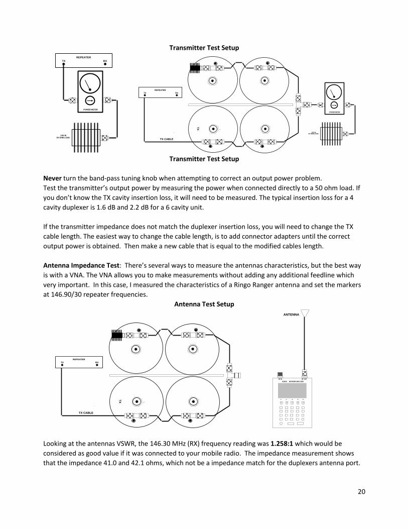
Transmitter Test Setup
Transmitter Test Setup
Never turn the band-pass tuning knob when attempting to correct an output power problem.
Test the transmitter’s output power by measuring the power when connected directly to a 50 ohm load. If
you don’t know the TX cavity insertion loss, it will need to be measured. The typical insertion loss for a 4
cavity duplexer is 1.6 dB and 2.2 dB for a 6 cavity unit.
If the transmitter impedance does not match the duplexer insertion loss, you will need to change the TX
cable length. The easiest way to change the cable length, is to add connector adapters until the correct
output power is obtained. Then make a new cable that is equal to the modified cables length.
Antenna Impedance Test: There’s several ways to measure the antennas characteristics, but the best way
is with a VNA. The VNA allows you to make measurements without adding any additional feedline which
very important. In this case, I measured the characteristics of a Ringo Ranger antenna and set the markers
at 146.90/30 repeater frequencies.
Antenna Test Setup
Looking at the antennas VSWR, the 146.30 MHz (RX) frequency reading was 1.258:1 which would be
considered as good value if it was connected to your mobile radio. The impedance measurement shows
that the impedance 41.0 and 42.1 ohms, which not be a impedance match for the duplexers antenna port.
50 OHM LOAD
POWER METER
TX
REPEATER
RX
100 W
TX RX
POWER METER
REPEATER
100 W
TX
50 OHM LOAD
TX CABLE
TX
TX CABLE
TO ANT.
TX
KC901S NETWORK ANALYZER
RF OUTRF IN
RX
REPEATER
ANTENNA
RF IN RF OUT
KC901S NETWORK ANALYZER

21
VSWR Impedance (Z)
Receiver Port Impedance Test: The duplexer’s antenna port was terminated with a 50 ohm load and a
Return Loss Bridge was used to measure the RX port value. This test showed RX port Return Loss as being
40.2 dB with 50 ohm load which equals to a VSWR of 1.02:1. and an impedance of 51 ohms.
Replacing the 50 ohm load with the antenna not only caused a change in Return Loss response, it reduced
the Return Loss value to 21.7 dB.
The screen plot below shows the results of adding 12.5 inches to the antenna feedline, the duplexers tuning
was restored and the Return Loss was 38.14 dB. Note: Page 9 of this documents explains how the
impedance of a coaxial cable can change when not terminated with 50 ohms. In this case, this phenomena
was used to correct the impedance mismatch.
RF INPUT
RF INPUTGEN. OUT
N9340BAgilent Technologies
WILTRON
RX
100 kHz - 3.0 GHz
TX
TRACKING
HIG
H P
AS
S
HANDHELD SPECTRUM ANALYZER
LO
W P
AS
S
REFL. PWR
RF BRIDGE
RF INPUT
RF BRIDGEWILTRON
TX
HANDHELD SPECTRUM ANALYZER
LO
W P
AS
S
ANTENNA
RX
N9340B
HIG
H P
AS
S
100 kHz - 3.0 GHz
REFL. PWR
GEN. OUTTRACKING
RF INPUT
Agilent Technologies
22
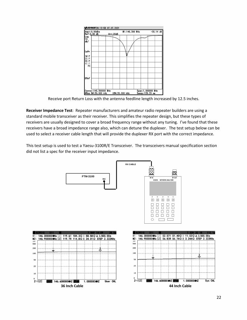
Receive port Return Loss with the antenna feedline length increased by 12.5 inches.
Receiver Impedance Test: Repeater manufacturers and amateur radio repeater builders are using a
standard mobile transceiver as their receiver. This simplifies the repeater design, but these types of
receivers are usually designed to cover a broad frequency range without any tuning. I’ve found that these
receivers have a broad impedance range also, which can detune the duplexer. The test setup below can be
used to select a receiver cable length that will provide the duplexer RX port with the correct impedance.
This test setup is used to test a Yaesu-3100R/E Transceiver. The transceivers manual specification section
did not list a spec for the receiver input impedance.
36 Inch Cable 44 Inch Cable
RF IN
RX CABLE
RX
FTM-3100RF OUT
KC901S NETWORK ANALYZER
23
Connecting the Yaesu transceiver to the duplexer RX port with a 36” cable would destroy the RX cavity
tuning and result in weak signal receiving problems. The 44” cable would provide 52.5 ohm match to the
RX port at the 146.30 MHz RX frequency.
End of Document
Jerry Ritchie WA5OKO