VHDL Training ©1997 Cypress Semiconductor, rev 2.5.3 1 PROGRAMMABLE LOGIC DESIGN WITH VHDL.
138
VHDL Training ©1997 Cypress Semiconductor, rev 2.5.3 1 PROGRAMMABLE LOGIC DESIGN WITH VHDL
-
Upload
nelson-harris -
Category
Documents
-
view
232 -
download
2
Transcript of VHDL Training ©1997 Cypress Semiconductor, rev 2.5.3 1 PROGRAMMABLE LOGIC DESIGN WITH VHDL.

VHDL Training
©1997 Cypress Semiconductor, rev 2.5.31
PROGRAMMABLE LOGIC DESIGN WITH VHDL

VHDL Training
©1997 Cypress Semiconductor, rev 2.5.32
Objectives
Upon completion of this training, your VHDL knowledge will enable you to:
Implement efficient combinatorial and sequential logic Design state machines and understand implementation trade-offs Use hierarchy / Create reusable components Identify how VHDL will synthesize and fit into a PLD or CPLD

VHDL Training
©1997 Cypress Semiconductor, rev 2.5.33
Agenda
Introduction, Why Use VHDL? PLD Design Flow VHDL Design Descriptions The Entity, Ports, Modes, Types Exercise #1 The Architecture, Architecture Styles VHDL Statements, Combinational Logic Processes, Signals vs. Variables VHDL Operators/Overloading/Inferencing Tri-State Logic, Don't Cares VHDL Identifiers Exercise #2, Exercise #3 Registers/Sequential Logic
Wait Statement, Implicit Memory
Exercise #4 - Lunch State Machines and State
Encoding Exercise #5 Hierarchy (components,
packages, and libraries) Exercise #6 Generate Statement Multiplexing I/O pins Exercise #7 Attributes, Miscellaneous
Topics, Wrap-up

VHDL Training
©1997 Cypress Semiconductor, rev 2.5.34
Introduction
VHDL is used to: document circuits simulate circuits synthesize design descriptions
Synthesis is the reduction of a design description to a lower-level representation (such as a netlist or a set of equations).
This training course covers VHDL for PLD synthesis The course will at times draw upon the concepts of
VHDL as a simulation language

VHDL Training
©1997 Cypress Semiconductor, rev 2.5.35
Why Use VHDL? Quick Time-to-Market
Allows designers to quickly develop designs requiring tens of thousands of logic gates
Provides powerful high-level constructs for describing complex logic
Supports modular design methodology and multiple levels of hierarchy
One language for design and simulation Allows creation of device-independent designs that are
portable to multiple vendors. Allows user to pick any synthesis tool, vendor, or device

VHDL Training
©1997 Cypress Semiconductor, rev 2.5.36
PLD Design Flow
Design Entry Schematic Capture/HDL or Both Front-End Simulation (optional)
Design Compilation Synthesis, Fitting/Place&Route
Design Verification Back-End Simulation (optional) Device Programming

VHDL Training
©1997 Cypress Semiconductor, rev 2.5.37
FrontEnd
BackEnd
Schematic Text
Synthesis
Fitting Place&Route
Simulation
Sim. Model
DesignEntry
DesignCompilation
SimulationJEDEC
FileProg.File
DesignVerification
Programmer

VHDL Training
©1997 Cypress Semiconductor, rev 2.5.38
VHDL Design Descriptions
VHDL design descriptions (referred to as "design entities") consist of an ENTITY declaration and ARCHITECTURE body pair
The ENTITY declaration describes the design I/O
The ARCHITECTURE body describes the content of the design

VHDL Training
©1997 Cypress Semiconductor, rev 2.5.39
VHDL Entity/Architecture Pairs:2-Input And Function
ENTITY and2 IS PORT (
a,b : IN std_logic;
f: OUT std_logic);
END and2;
ARCHITECTURE behavioral OF and2 IS
BEGIN
f <= a AND b;
END behavioral;

VHDL Training
©1997 Cypress Semiconductor, rev 2.5.310
The Entity
A “BLACK BOX” The ENTITY describes the periphery of the
black box (i.e., the design I/O)
BLACK_BOX
rst
d[7:0]
clk
q[7:0]
co

VHDL Training
©1997 Cypress Semiconductor, rev 2.5.311
Example Entity declaration
ENTITY black_box IS PORT (
clk, rst: IN std_logic;
d: IN std_logic_vector(7 DOWNTO 0);
q: OUT std_logic_vector(7 DOWNTO 0);
co: OUT std_logic);
END black_box;
More shortly
BLACK_BOX
rst
d[7:0]
clk
q[7:0]
co
VHDL Training
©1997 Cypress Semiconductor, rev 2.5.312
ENTITY entity_name IS PORT (
-- optional generics
name : mode type ;
...
) ;
END entity_name;
entity_name is an arbitrary name generics are used for defining paramaterized components name is the signal/port identifier and may be a comma
separate list for ports of identical modes and types mode describes the direction the data is flowing type indicates the set of values the port name may be
assigned
The Entity Declaration

VHDL Training
©1997 Cypress Semiconductor, rev 2.5.313
Ports
The Entity (“BLACK BOX”) has PORTS PORTS are points of communication
• PORTS are often associated with the device pins PORTS are a special class of SIGNAL PORTS have an associated SIGNAL name,
mode, and type
VHDL Training
©1997 Cypress Semiconductor, rev 2.5.314
PORT modes
A port’s MODE is the direction data is transferred:
IN Data goes into the entity but not out
OUT Data goes out of the entity but not in (and is not used internally)
INOUT Data is bi-directional (goes into and out of the entity)
BUFFER Data that goes out of the entity and is also fed-back internally within
the entity

VHDL Training
©1997 Cypress Semiconductor, rev 2.5.315
IEEE 1076 Types VHDL is a strongly typed language (you cannot assign a signal of
one type to the signal of another type) bit - a signal of type bit that can only take values of '0' or '1' bit_vector - a grouping of bits (each can be '0' or '1')
SIGNAL a: BIT_VECTOR(0 TO 3); -- ascending rangeSIGNAL b: BIT_VECTOR(3 DOWNTO 0); -- descending range
a <= "0111"; -- double quotes used for vectors
b <= "0101";This means that: a(0) = '0' b(0) = '1'
a(1) = '1' b(1) = '0'
a(2) = '1' b(2) = '1'
a(3) = '1' b(3) = '0'

VHDL Training
©1997 Cypress Semiconductor, rev 2.5.316
INTEGER
• useful as index holders for loops, constants, generics, or high-level modeling
BOOLEAN
• can take values ‘TRUE’ or ‘FALSE’ ENUMERATED
• has user defined set of possible values, e.g.,
• TYPE states IS (start, slow, fast, stop);
IEEE 1076 TYPES (contd.)

VHDL Training
©1997 Cypress Semiconductor, rev 2.5.317
IEEE 1164
"Multi-value logic system for VHDL interoperability" A package created as an aid to VHDL users Nine values as opposed to two ('0' and '1') Allows increased flexibility in behavioral VHDL
coding, synthesis, and simulation std_logic and std_logic_vector are used as opposed to
bit and bit_vector when a multi-valued logic system is required.
std_logic and std_logic_vector are used when tri-state logic is required.

VHDL Training
©1997 Cypress Semiconductor, rev 2.5.318
1164 Types
std_logic and std_logic_vector are the industry standard logic type for digital design
All 9 values are valid in a VHDL simulator, however only: ‘0’ -- Forcing ‘0’ ‘1’ -- Forcing ‘1’ ‘Z’ -- High Impedance ‘L’ -- Weak ‘0’ ‘H’ -- Weak ‘1’ ‘-’ -- Don’t care
are recognized for logic synthesis
VHDL Training
©1997 Cypress Semiconductor, rev 2.5.319
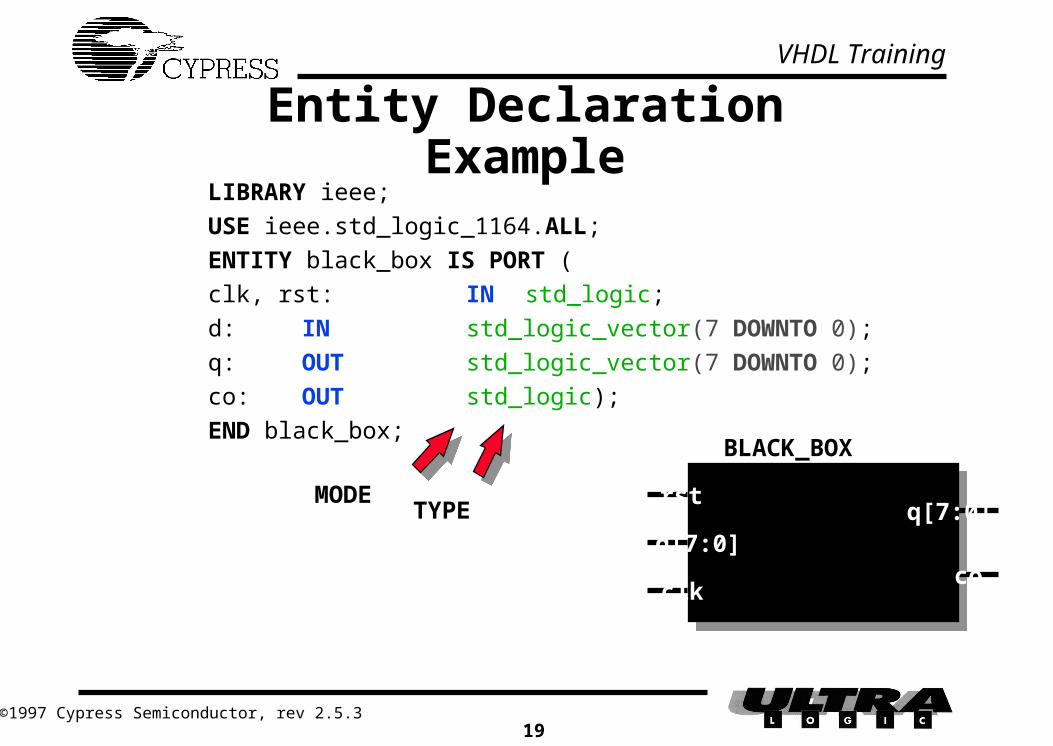
Entity Declaration ExampleLIBRARY ieee;
USE ieee.std_logic_1164.ALL;
ENTITY black_box IS PORT (
clk, rst: IN std_logic;
d: IN std_logic_vector(7 DOWNTO 0);
q: OUT std_logic_vector(7 DOWNTO 0);
co: OUT std_logic);
END black_box;BLACK_BOX
rst
d[7:0]
clk
q[7:0]
co
MODETYPE
VHDL Training
©1997 Cypress Semiconductor, rev 2.5.320
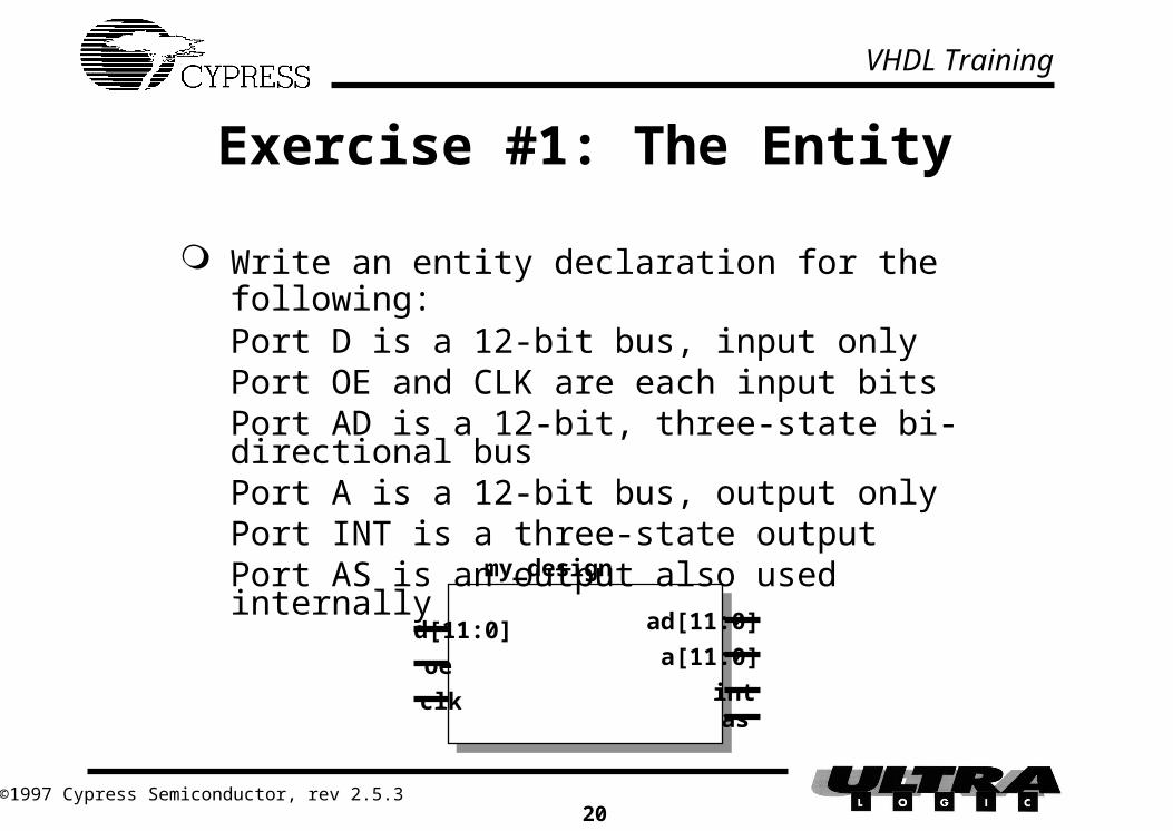
Exercise #1: The Entity
Write an entity declaration for the following:Port D is a 12-bit bus, input onlyPort OE and CLK are each input bitsPort AD is a 12-bit, three-state bi-directional
busPort A is a 12-bit bus, output onlyPort INT is a three-state outputPort AS is an output also used internallymy_design
d[11:0]
oe
clk
ad[11:0]
a[11:0]
intas

VHDL Training
©1997 Cypress Semiconductor, rev 2.5.321
Exercise #1: SolutionLIBRARY ieee;USE ieee.std_logic_1164.ALL;ENTITY my_design IS PORT (
d: IN std_logic_vector(11 DOWNTO 0);oe, clk: IN std_logic;ad: INOUT std_logic_vector(11 DOWNTO 0);a: OUT std_logic_vector(11 DOWNTO 0);int: OUT std_logic;as: BUFFER std_logic);
END my_design;-- In this presentation, VHDL keywords -- are highlighted in bold, CAPITALS;-- however, VHDL is not case sensitive: -- clock, Clock, CLOCK all refer to the-- same signal, -- means a comment
my_design
d[11:0]
oe
clk
ad[11:0]
a[11:0]
intas

VHDL Training
©1997 Cypress Semiconductor, rev 2.5.322
The Architecture Architectures describe what is in the black box (i.e., the
structure or behavior of entities) Descriptions can be either a combination of
Structural descriptions
• Instantiations (placements of logicmuch like in a schematicand their connections) of building blocks referred to as components
Behavioral/Dataflow descriptions
• Algorithmic (or “high-level”) descriptions:IF a = b THEN state <= state5;
• Boolean equations (also referred to as dataflow):x <= (a OR b) AND c;

VHDL Training
©1997 Cypress Semiconductor, rev 2.5.323
ARCHITECTURE arch_name OF entity_name IS
-- optional signal declarations, etc.
BEGIN
--VHDL statements
END arch_name;
arch_name is an arbitrary name optional signal declarations are used for signals local to
the architecture body (that is, not the entity’s I/O). entity_name is the entity name statements describe the function or contents of the entity
The Architecture Declaration
VHDL Training
©1997 Cypress Semiconductor, rev 2.5.324
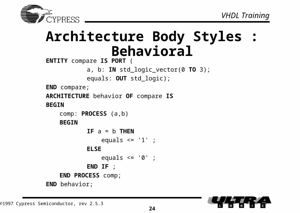
Architecture Body Styles : BehavioralENTITY compare IS PORT (
a, b: IN std_logic_vector(0 TO 3);
equals: OUT std_logic);
END compare;
ARCHITECTURE behavior OF compare IS
BEGIN
comp: PROCESS (a,b)
BEGIN
IF a = b THEN
equals <= '1' ;
ELSE
equals <= '0' ;
END IF ;
END PROCESS comp;
END behavior;

VHDL Training
©1997 Cypress Semiconductor, rev 2.5.325
Architecture Body Styles : Dataflow
ENTITY compare IS PORT (
a, b: IN std_logic_vector(0 TO 3);
equals: OUT std_logic);
END compare;
ARCHITECTURE dataflow OF compare IS
BEGIN
equals <= '1' WHEN a = b ELSE '0' ;
END dataflow;

VHDL Training
©1997 Cypress Semiconductor, rev 2.5.326
Architecture Body Styles : StructuralENTITY compare IS PORT (
a, b: IN std_logic_vector(0 TO 3);
equals: OUT std_logic);
END compare;
USE WORK.gatespkg.ALL ;
ARCHITECTURE structure OF compare IS
SIGNAL x : std_logic_vector (0 to 3) ;
BEGIN
u0: xnor2 PORT MAP (a(0),b(0),x(0)) ;
u1: xnor2 PORT MAP (a(1),b(1),x(1)) ;
u2: xnor2 PORT MAP (a(2),b(2),x(2)) ;
u3: xnor2 PORT MAP (a(3),b(3),x(3)) ;
u4: and4 PORT MAP (x(0),x(1),x(2),x(3),equals) ;
END structure;

VHDL Training
©1997 Cypress Semiconductor, rev 2.5.327
Comparing Architecture Styles
These examples synthesize to equivalent circuits In more elaborate designs, some descriptions may yield
more efficient circuits sloppy code = inefficient results (see section 3.3.4)
Use styles that make your designs easier to describe and maintain Behavioral/Dataflow exploit module generation
(described later) Structural descriptions may make the design less
portable (may rely on a library of vendor-specific components)

VHDL Training
©1997 Cypress Semiconductor, rev 2.5.328
Mixing Architecture Styles The various styles may be mixed in one architecture.
ENTITY logic IS PORT (
a,b,c: IN std_logic;
f: OUT std_logic);
END logic;
USE WORK.gatespkg.ALL;
ARCHITECTURE archlogic OF logic IS
SIGNAL d: std_logic;
BEGIN
d <= a AND b;
g1: nor2 PORT MAP (c, d, f);
END archlogic;
ab
c
d
f
LOGIC
Behavioral/Dataflow
Structural
g1

VHDL Training
©1997 Cypress Semiconductor, rev 2.5.329
VHDL Statements There are two types of statements
Sequential
• Though hardware is concurrent, it may be modeled with algorithms, by a series of sequential statements
• By definition, sequential statements are grouped using a process statement.
Concurrent
• Statements outside of a process are evaluated concurrently during simulation
• Processes are concurrent statements

VHDL Training
©1997 Cypress Semiconductor, rev 2.5.330
Concurrent Statements Concurrent statements include:
boolean equations conditional/selective signal assignments (when/else,
with/select) instantiations
Examples of concurrent statements:
-- Examples of boolean equations
x <= (a AND (NOT sel1)) OR (b AND sel1);
g <= NOT (y AND sel2);
-- Examples of conditional assignments
y <= d WHEN (sel1 = '1') ELSE c;
h <= '0' WHEN (x = '1' AND sel2 = '0') ELSE '1';
-- Examples of instantiation
inst: nand2 PORT MAP (h, g, f);

VHDL Training
©1997 Cypress Semiconductor, rev 2.5.331
The Process Statement
Used to construct algorithms/group sequential statements
Statements within a process are sequential statementsthey execute sequentially during simulation
An architecture can contain multiple processes. Each process is executed concurrently
Processes may be used to model combinational or synchronous logic

VHDL Training
©1997 Cypress Semiconductor, rev 2.5.332
The Process (contd.)
label: PROCESS (sensitivity list)
-- variable declarations
BEGIN
-- sequential statements
END PROCESS label ;
The process label and variable declarations are optional
The process executes when one of the signals in the sensitivity list has an event (changes value).

VHDL Training
©1997 Cypress Semiconductor, rev 2.5.333
Process (contd.)
Processes are executing or suspended (active or inactive/awake or asleep)
A process typically has a sensitivity list When a signal in the sensitivity list changes value,
the process is executed by the simulator e.g., a process with a clock signal in its sensitivity
list becomes active on changes of the clock signal All signal assignments occur at the END PROCESS
statement in terms of simulation The process is then suspended until there is an event
(change in value) on a signal in the sensitivity list

VHDL Training
©1997 Cypress Semiconductor, rev 2.5.334
Combinational Logic
Can be described with concurrent statements e.g. with-select-when, when-else, boolean
equations, component instantiatons Can be described with sequential statements
e.g. if-then-else, case-when

VHDL Training
©1997 Cypress Semiconductor, rev 2.5.335
Combinational Logic w/ Boolean Equations
Boolean Equations can be used in both concurrent and sequential signal assignment statements.
A 4-1 multiplexer is shown below
x <= (a AND NOT(s(1)) AND NOT(s(0))) OR
(b AND NOT(s(1)) AND s(0)) OR
(c AND s(1) AND NOT(s(0))) OR
(d AND s(1) AND s(0)) ;
ax
muxcb
d
s
2

VHDL Training
©1997 Cypress Semiconductor, rev 2.5.336
Selective Signal Assignment:with-select-when
Assignment based on a selection signal WHEN clauses must be mutually exclusive Use a WHEN OTHERS to avoid latches Only one reference to the signal, only one assignment operator (<=)
WITH selection_signal SELECT
signal_name <= value_1 WHEN value_1 of selection_signal,
value_2 WHEN value_2 of selection_signal,
...
value_n WHEN value_n of selection_signal,
value_x WHEN OTHERS;

VHDL Training
©1997 Cypress Semiconductor, rev 2.5.337
Combinational Logic w/ Selective Signal Assignment
The same 4-1 multiplexer is shown below
with s select
x <= a when “00” ,
b when “01” ,
c when “10” ,
d when others ;

VHDL Training
©1997 Cypress Semiconductor, rev 2.5.338
More on with-select-when
You can use a range of values
with int_value select
x <= a when 0 to 3,
b when 4 | 6 | 8 ,
c when 10 ,
d when others ;

VHDL Training
©1997 Cypress Semiconductor, rev 2.5.339
Conditional Signal Assignment:when-else
Signal is assigned a value based on conditions Any simple expression can be a condition Priority goes in order of appearance Only one reference to the signal, only one assignment
operator (<=) Use a final ELSE to avoid latches
signal_name <= value_1 WHEN condition1 ELSE
value_2 WHEN condition2 ELSE
...
value_n WHEN conditionn ELSE
value_x ;

VHDL Training
©1997 Cypress Semiconductor, rev 2.5.340
Combinational Logic w/ Conditional Signal Assignment
The same 4-1 multiplexer is shown below
x <= a when (s = “00”) else
b when (s = “01”) else
c when (s = “10”) else
d ;

VHDL Training
©1997 Cypress Semiconductor, rev 2.5.341
Combinational Logic w/ Conditional Signal Assignment
The when conditions do not have to be mutually exclusive (as in with-select-when)
A priority encoder is shown below
j <= w when (a = ‘1’) else
x when (b = ‘1’) else
y when (c = ‘1’) else
z when (d = ‘1’) else
‘0’ ;

VHDL Training
©1997 Cypress Semiconductor, rev 2.5.342
Combinational Logic w/ Sequential Statements
Grouped together with Processes Processes are concurrent with one another and with
concurrent statements Order of sequential statements does make a
difference in synthesis

VHDL Training
©1997 Cypress Semiconductor, rev 2.5.343
Sequential Statementsif-then-else
Used to select a set of statements to be executed Selection based on a boolean evaluation of a condition or
set of conditions
IF condition(s) THEN
do something;
ELSIF condition_2 THEN -- optional
do something different;
ELSE -- optional
do something completely different;
END IF ;

VHDL Training
©1997 Cypress Semiconductor, rev 2.5.344
if-then-else
Absence of ELSE results in implicit memory 4-1 mux shown below
mux4_1: process (a, b, c, d, s)
begin
if s = “00” then x <= a ;
elsif s = “01” then x <= b ;
elsif s = “10” then x <= c ;
else x <= d ;
end process mux4_1 ;

VHDL Training
©1997 Cypress Semiconductor, rev 2.5.345
Sequentional Statements: Case-When
CASE selection_signal
WHEN value_1_of_selection_signal =>
(do something) -- set of statements 1
WHEN value_2_of_selection_signal =>
(do something) -- set of statements 2
...
WHEN value_N_of_selection_signal =>
(do something) -- set of statements N
WHEN OTHERS =>
(do something) -- default action
END CASE ;

VHDL Training
©1997 Cypress Semiconductor, rev 2.5.346
The CASE Statement: 4-1 Mux
ARCHITECTURE archdesign OF design ISSIGNAL s: std_logic_vector(0 TO 1);
BEGINmux4_1: PROCESS (a,b,c,d,s)BEGIN
CASE s ISWHEN "00" => x <= a;WHEN "01" => x <= b;WHEN "10” => x <= c;WHEN OTHERS => x <= d;
END CASE;END PROCESS mux4_1;
END archdesign;

VHDL Training
©1997 Cypress Semiconductor, rev 2.5.347
Sequential Statements: An Example
mux: PROCESS (a, b, s)
BEGIN
IF s = '0' THEN
x <= a;
ELSE
x <= b;
END IF;
END PROCESS mux;
Note: logic within a process can be registered or combinatorial Note: the order of the signals in the sensitivity list is not important Note: the process mux is sensitive to signals a, b, and s; i.e., whenever one
or more of those signals changes value, the statements inside of the process are executed
x(3 DOWNTO 0)
s
a(3 DOWNTO 0)
b(3 DOWNTO 0)

VHDL Training
©1997 Cypress Semiconductor, rev 2.5.348
Signal Assignment in ProcessesWhich Circuit is Correct?
PROCESS
BEGIN
WAIT UNTIL clock = '1' ; -- implied sensitivity list
b <= a;
c <= b;
END PROCESS ;
a
clock
ca c
b
clock

VHDL Training
©1997 Cypress Semiconductor, rev 2.5.349
Signal Assignment in Processes (contd.)
Signals are not updated immediately. Rather, they are scheduled.
The signals are not updated until time advances (after the End Process statement)
Therefore, two registers will be synthesized Note: In some instances, the use of concurrent
statements outside the process may alleviate the problem, but this is not possible with registered logic.

VHDL Training
©1997 Cypress Semiconductor, rev 2.5.350
VARIABLES
When a concurrent signal assignment cannot be used, the previous problem can be avoided using a VARIABLE
Variables can only exist within a PROCESS, they cannot be used to communicate information between processes
Variables can be of any valid data type The value assigned to a variable is available
immediately The variable assignment statement is used to
assign values to variables, e.g.,
c := a AND b;

VHDL Training
©1997 Cypress Semiconductor, rev 2.5.351
Using Variables vs. Signals
Solution using a variable within a process:
-- assume a and c are signals defined elsewhere
PROCESS
VARIABLE b : std_logic ;
BEGIN
WAIT UNTIL clock = '1' ;
b := a ; -- this is immediate
c <= b ; -- this is scheduled
END PROCESS ;

VHDL Training
©1997 Cypress Semiconductor, rev 2.5.352
Native Operators Logical - defined for type bit, bit_vector, boolean*
AND, NAND OR, NOR XOR, XNOR NOT
Relational - defined for types bit, bit_vector, integer* = (equal to) /= (not equal to) < (less than) <= (less than or equal to) > (greater than) >= (greater than or equal to)
* overloaded for std_logic, std_logic_vector
VHDL Training
©1997 Cypress Semiconductor, rev 2.5.353
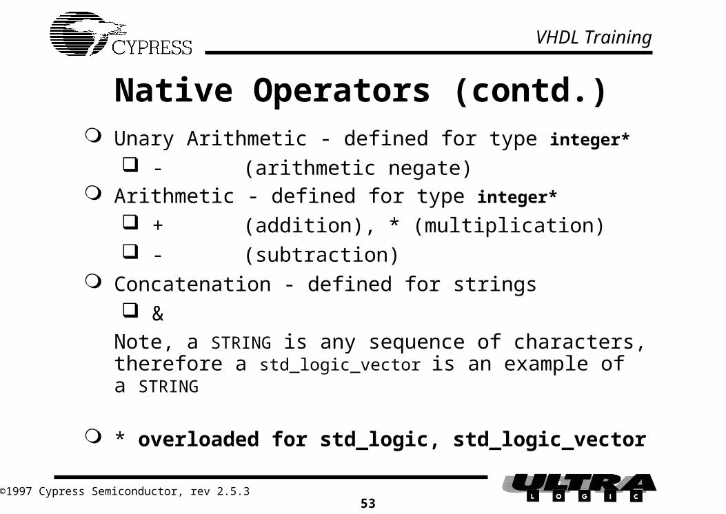
Native Operators (contd.) Unary Arithmetic - defined for type integer*
- (arithmetic negate) Arithmetic - defined for type integer*
+ (addition), * (multiplication) - (subtraction)
Concatenation - defined for strings &
Note, a STRING is any sequence of characters, therefore a std_logic_vector is an example of a STRING
* overloaded for std_logic, std_logic_vector

VHDL Training
©1997 Cypress Semiconductor, rev 2.5.354
Overloaded Operators In VHDL, the scope of all of the previous operators
can be extended (or overloaded) to accept any type supported by the language, e.g.,-- assume a declaration of a 16-bit vector as
SIGNAL pc IS std_logic_vector(15 DOWNTO 0);
-- then a valid signal assignment is
pc <= pc + 3;
-- assuming the '+' operator has been overloaded to --- accept std_logic_vector and integer operands
The std_logic_1164 package defines overloaded logical operators (AND, OR, NOT, etc.,) for the std_logic and std_logic_vector types
In this training, you will learn to use overloaded operators, but not to define them

VHDL Training
©1997 Cypress Semiconductor, rev 2.5.355
Using Tri-State LogicENTITY test_three IS
PORT( oe : in std_logic;
data : out std_logic_vector(0 to 7));
END test_three;
ARCHITECTURE archtest_three OF test_three IS
BEGIN
PROCESS (oe)
BEGIN
IF (oe = '1') THEN
data <= "01100100";
ELSE
data <= "ZZZZZZZZ";
END IF;
END PROCESS;
END archtest_three;

VHDL Training
©1997 Cypress Semiconductor, rev 2.5.356
Behavioral Don’t Cares
Can use explicit "don’t care" conditions to produce optimal logic equations
IF (a = '1') AND (b = '1') THENx <= c;
ELSEx <= '-';
END IF; Produces the equation x = c To assign don’t cares in VHDL: mysig <= '-';
'X' means "unknown" and is not useful for synthesis

VHDL Training
©1997 Cypress Semiconductor, rev 2.5.357
Comparing Vectors to Strings-more on don't cares-
Comparing "1101" to "11-1" will return FALSE Use std_match(a,"string") Must include std_arith package Example:...
signal a : stdlogic_vector (1 to 4) ;
...
IF (std_match(a,"10-1")) THEN
x <= '1' ;
END IF ;
VHDL Training
©1997 Cypress Semiconductor, rev 2.5.358
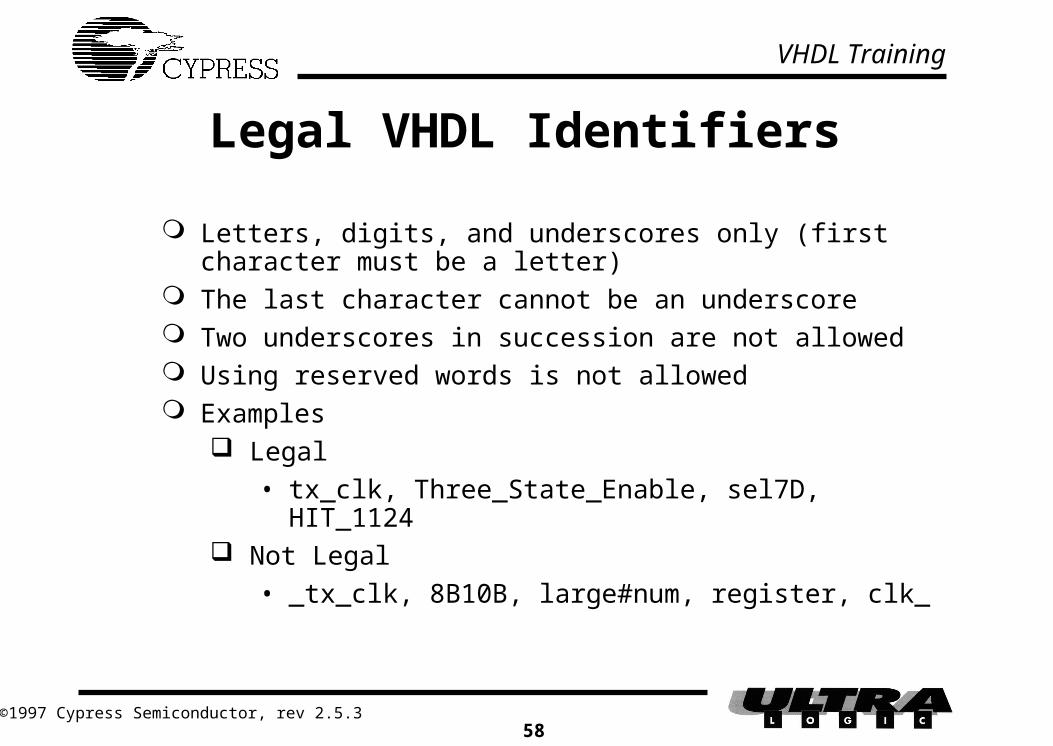
Legal VHDL Identifiers
Letters, digits, and underscores only (first character must be a letter)
The last character cannot be an underscore Two underscores in succession are not allowed Using reserved words is not allowed Examples
Legal
• tx_clk, Three_State_Enable, sel7D, HIT_1124 Not Legal
• _tx_clk, 8B10B, large#num, register, clk_

VHDL Training
©1997 Cypress Semiconductor, rev 2.5.359
Exercise #2: Architecture Declaration of a Comparator
The entity declaration is as follows:
LIBRARY ieee;
USE ieee.std_logic_1164.ALL;
ENTITY compare IS PORT (
a, b: IN std_logic_vector(0 TO 3);
aeqb: OUT std_logic);
END compare;
Write an architecture that causes aeqb to be asserted when a is equal to b
Multiple solutions exist
aeqba(0 TO 3)
b(0 TO 3)

VHDL Training
©1997 Cypress Semiconductor, rev 2.5.360
Three possible solutions Concurrent statement solution using a conditional assignment:
Concurrent statement solution using boolean equations:
ARCHITECTURE archcompare OF compare ISBEGIN
aeqb <= '1' WHEN a = b ELSE '0';END archcompare;
ARCHITECTURE archcompare OF compare ISBEGIN
aeqb <= NOT((a(0) XOR b(0)) OR(a(1) XOR b(1)) OR(a(2) XOR b(2)) OR(a(3) XOR b(3)));
END archcompare;

VHDL Training
©1997 Cypress Semiconductor, rev 2.5.361
Three possible solutions (contd.)
Solution using a process with sequential statements:
ARCHITECTURE archcompare OF compare IS
BEGIN
comp: PROCESS (a, b)
BEGIN
IF a = b THEN
aeqb <= '1';
ELSE
aeqb <= '0';
END IF;
END PROCESS comp;
END archcompare;
aeqba(0 TO 3)
b(0 TO 3)

VHDL Training
©1997 Cypress Semiconductor, rev 2.5.362
Exercise #3:The Schematic
en(1)
en(2)en(3)
en[0:3]
dir
en(0)dir
gnd
dir
CY74FCT373T
CY74FCT245T
PLD
CY74FCT373T
CY74FCT373T
addr[1:0]
nvalid
nOE
LE
nOE
LE
nOE
LE
data[7:0]
status[7:0] control[7:0]
T/R
nOEgnd

VHDL Training
©1997 Cypress Semiconductor, rev 2.5.363
Exercise #3 Use Warp to compile the VHDL design description
of the truth table below:
addr nvalid
b"00" '0'b"00" '1'b"01" '0'b"01" '1'b"10" '0'b"10" '1'b"11" '0'b"11" '1'
dir
LHHHLHHH
en(0) en(1) en(2) en(3)
L L H LH L H LH H H LH L H LH L L LH L H LH L H HH L H L
Write the Architecture for the given Entity (next) Save design in file named “ex3.vhd”

VHDL Training
©1997 Cypress Semiconductor, rev 2.5.364
Exercise #3:The Entity Declaration
the entity declaration is as follows:
LIBRARY ieee;
USE ieee.std_logic_1164.ALL;
ENTITY ex3 IS PORT (
addr: IN std_logic_vector(1 DOWNTO 0);
nvalid: IN std_logic;
en: BUFFER std_logic_vector(0 TO 3);
dir: OUT std_logic
);
END ex3;en
diraddr
nvalid
PLD

VHDL Training
©1997 Cypress Semiconductor, rev 2.5.365
Exercise #3: SolutionThe Architecture
The architecture is as follows:
ARCHITECTURE archex3 OF ex3 IS
BEGIN
en(0) <= '0' WHEN (addr = "00" AND nvalid = '0') ELSE '1';
en(1) <= (NOT addr(1)) AND addr(0) AND (NOT nvalid) ;
en(2) <= '0' WHEN (addr = "10" AND nvalid = '0') ELSE '1';
en(3) <= addr(1) AND addr(0) AND (NOT nvalid);
dir <= '0' WHEN (addr = "00" AND nvalid = '0') OR
(addr = "10" AND nvalid = '0') ELSE '1' ;
END archex3;

VHDL Training
©1997 Cypress Semiconductor, rev 2.5.366
Aggregates and Subscripts
Aggregate assignment concatenates signals together Good for creating a bus from several inputs Concatenation operator can be used as well Same number of array elements on both sides of <=
tmp <= (a,b,c,d); tmp <= a & b & c & d;
Signals can be “pulled” from larger vectors Good for grouping outputs as an “alias” Sizes on both sides must match
rw <= ctrl(0); ce <= ctrl(1); oe <= ctrl(2);
highcount <= count(7 DOWNTO 4);

VHDL Training
©1997 Cypress Semiconductor, rev 2.5.367
Exercise #3: Alternate Solution Using With/Select and aggregates
ARCHITECTURE archex3 OF ex3 IS SIGNAL control : std_logic_vector(2 DOWNTO 0); SIGNAL outputs : std_logic_vector(0 TO 4);BEGIN control <= addr & nvalid; WITH control SELECT outputs <= "00100" WHEN "000", "10101" WHEN "001", "11101" WHEN "010", "10101" WHEN "011", "10000" WHEN "100", "10101" WHEN "101", "10111" WHEN "110", "10101" WHEN "111", "-----" WHEN OTHERS; en <= outputs(0 TO 3); dir <= outputs(4);END archex3;
VHDL Training
©1997 Cypress Semiconductor, rev 2.5.368
Designs that use Registers
There are two methods of utilizing and generating flip-flops: Instantiate (place) a flip-flop or a component
that contains a flip-flop Use a process that is sensitive to a clock edge

VHDL Training
©1997 Cypress Semiconductor, rev 2.5.369
Instantiating a registered component Example: Using LPM library
LIBRARY ieee;
USE ieee.std_logic_1164.ALL;
USE WORK.lpmpkg.all ;
ENTITY registered IS PORT (
d, clk: IN std_logic;
q: OUT std_logic);
END registered;
ARCHITECTURE archregistered OF registered IS
BEGIN
flipflop: Mff generic map (lpm_width=>1,lpm_fftyp=>lpm_dff)
PORT MAP (data=>d,clock=>clk,enable=>one,q=>q);
END archregistered;
q d
clk

VHDL Training
©1997 Cypress Semiconductor, rev 2.5.370
Registers in Behavioral VHDL Example: a D-type flip-flop
ENTITY registered IS PORT (
d, clk: IN std_logic;
q: OUT std_logic);
END registered;
ARCHITECTURE archregistered OF registered IS
BEGIN
flipflop: PROCESS (clk)
BEGIN
IF clk’EVENT AND clk = '1' THEN
q <= d;
END IF;
END PROCESS flipflop;
END archregistered;

VHDL Training
©1997 Cypress Semiconductor, rev 2.5.371
Registers in Behavioral VHDL
The synthesis compiler infers that a register is to be created for which signal q is the output because The clock (clk) is in the sensitivity list The construct, clk’event and clk = ‘1’, appears in the
process The clk’event and clk = ‘1’ statement implies that subsequent
signal assignments occur on the rising-edge of the clock The absence of an “else” clause in the “if-then” statement
implies that if the clk’event and clk = ‘1’ condition is not fulfilled (i.e. not a rising-edge), q will retain its value until the next assignment occurs (this is referred to as implied memory)

VHDL Training
©1997 Cypress Semiconductor, rev 2.5.372
A Registered Process (1) A 4-bit counter with synchronous reset
USE WORK.std_arith.ALL;
...
upcount: PROCESS (clk)
BEGIN
IF clk’EVENT AND clk= '1' THEN
IF reset = '1' THEN
count <= "0000"; -- or x"0" instead
ELSE
count <= count + 1;
END IF;
END IF;
END PROCESS upcount; This process is only sensitive to changes in “clk”, i.e.,
it will become active only when the clock transitions
VHDL Training
©1997 Cypress Semiconductor, rev 2.5.373
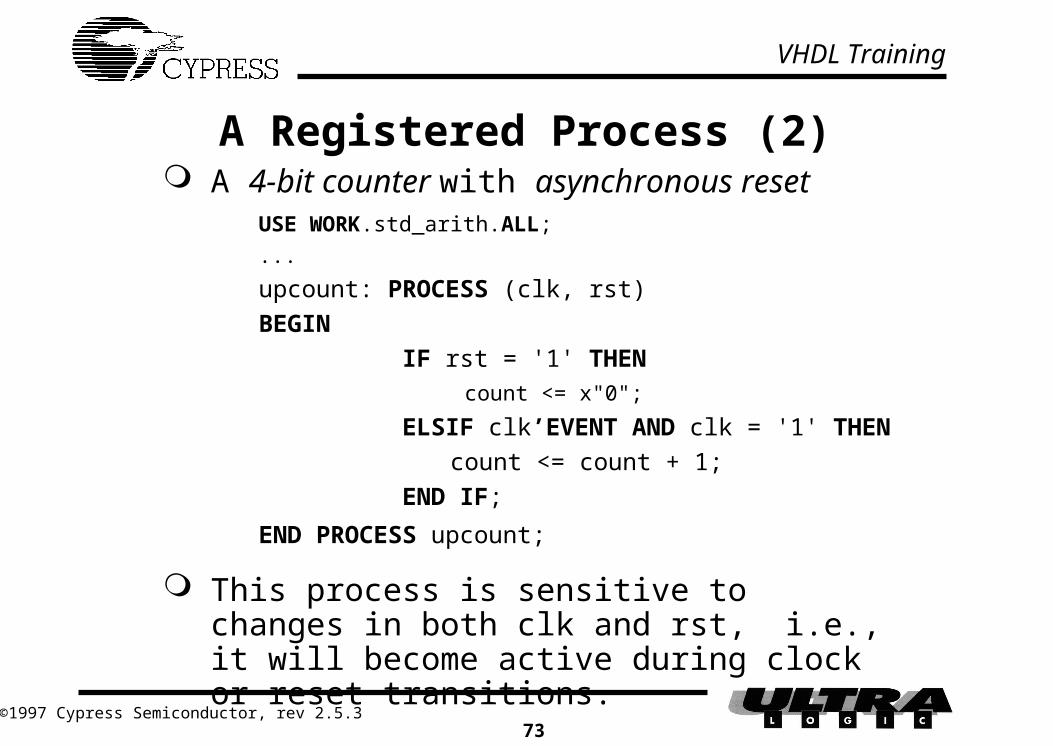
A Registered Process (2) A 4-bit counter with asynchronous reset
USE WORK.std_arith.ALL;
...
upcount: PROCESS (clk, rst)
BEGIN
IF rst = '1' THEN count <= x"0";
ELSIF clk’EVENT AND clk = '1' THEN
count <= count + 1;
END IF;
END PROCESS upcount;
This process is sensitive to changes in both clk and rst, i.e., it will become active during clock or reset transitions.
VHDL Training
©1997 Cypress Semiconductor, rev 2.5.374
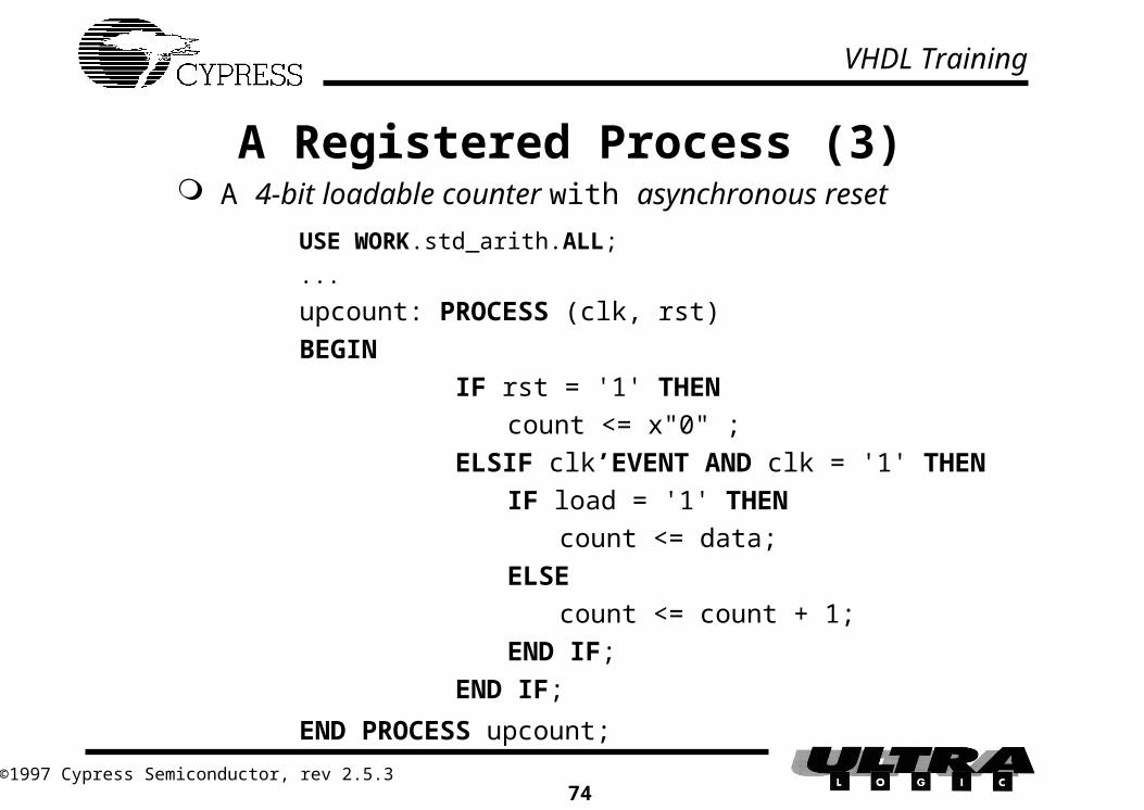
A Registered Process (3) A 4-bit loadable counter with asynchronous reset
USE WORK.std_arith.ALL;
...
upcount: PROCESS (clk, rst)
BEGIN
IF rst = '1' THEN
count <= x"0" ;
ELSIF clk’EVENT AND clk = '1' THEN
IF load = '1' THEN
count <= data;
ELSE
count <= count + 1;
END IF;
END IF;
END PROCESS upcount;

VHDL Training
©1997 Cypress Semiconductor, rev 2.5.375
The WAIT statement This is another method to activate a process The WAIT statement is a sequential statement which
suspends the execution of a process until the condition specified becomes valid (true) i.e., an implied sensitivity list, e.g.,
sync: PROCESS
BEGIN
WAIT UNTIL clock='1';
IF enable='1' THEN
q_out <= d_in;
ELSE
q_out <= '0';
END IF;
END PROCESS sync;
D
enable
d_in
clock
Qq_out

VHDL Training
©1997 Cypress Semiconductor, rev 2.5.376
Implicit memory
Signals in VHDL have a current value and may be scheduled for a future value
If the future value of a signal cannot be determined, a latch will be synthesized to preserve its current value
Advantages: Simplifies the creation of memory in logic
design Disadvantages:
Can generate unwanted latches, e.g., when all of the options in a conditional sequential statement are not specified

VHDL Training
©1997 Cypress Semiconductor, rev 2.5.377
Implicit memory:Example of incomplete specification
Note: the incomplete specification of the IF...THEN... statement causes a latch to be synthesized to store the previous state of ‘c’
ARCHITECTURE archincomplete OF incomplete IS
BEGIN
im_mem: PROCESS (a,b)
BEGIN
IF a = '1' THEN c <= b;
END IF;
END PROCESS im_mem;
END archincomplete;
ac
b
VHDL Training
©1997 Cypress Semiconductor, rev 2.5.378
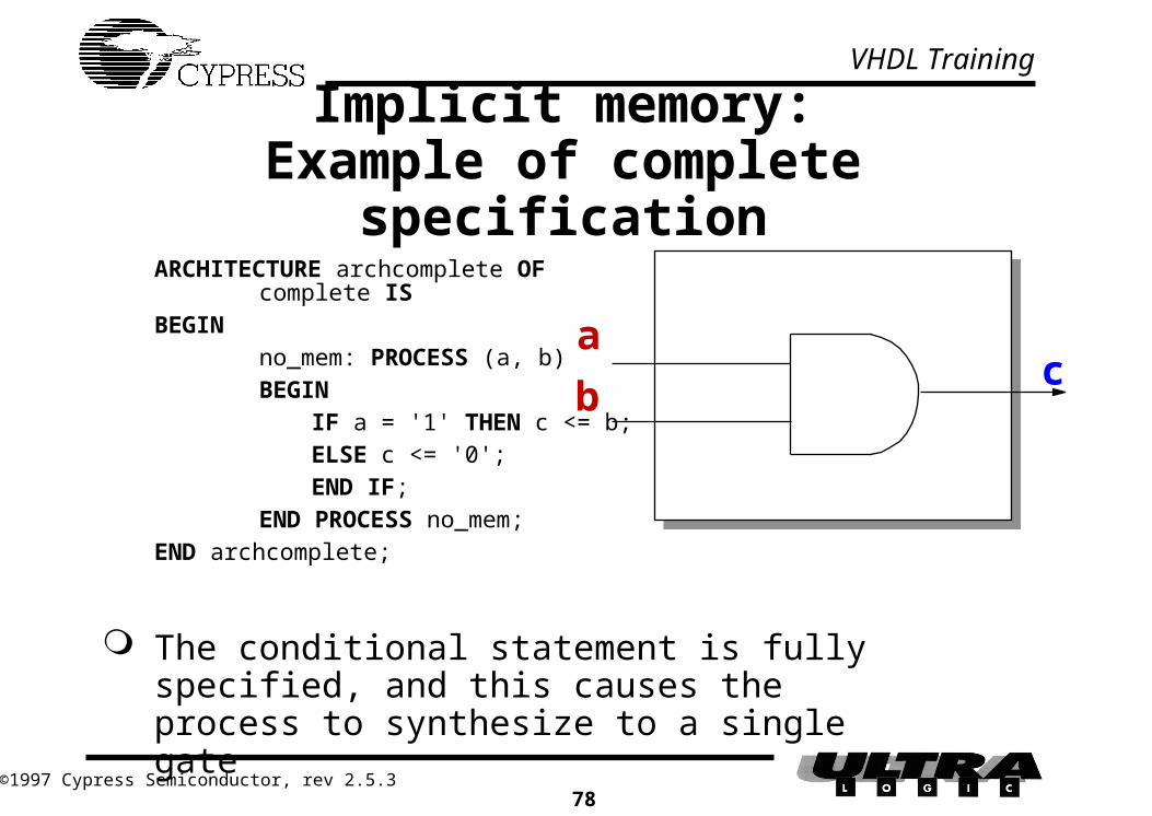
Implicit memory:Example of complete specification
The conditional statement is fully specified, and this causes the process to synthesize to a single gate
ARCHITECTURE archcomplete OFcomplete IS
BEGINno_mem: PROCESS (a, b)BEGIN
IF a = '1' THEN c <= b;ELSE c <= '0';END IF;
END PROCESS no_mem;END archcomplete;
bc
a

VHDL Training
©1997 Cypress Semiconductor, rev 2.5.379
The rules to avoid implicit memory To avoid the generation of unexpected latches
always terminate an IF...THEN... statement with an ELSE clause
cover all alternatives in a CASE statement
• define every alternative individually, or
• terminate the CASE statement with a WHEN OTHERS... clause, e.g.,CASE select IS
WHEN b"100" => key <= first;
x <= a AND b;
WHEN b"010" => key <= second;
WHEN b"001" => key <= third;
WHEN OTHERS => key <= none;
END CASE;

VHDL Training
©1997 Cypress Semiconductor, rev 2.5.380
Exercise #4 Making use of the previous examples, write an
entity/architecture pair for the following design:
ENR
DIN
Q
REGISTER
4
4
Q
P
P=Q
COMPARATOR
4
COUNT
CLOCK
ENC
LD
DATA
ENR
RESET (sync)
ENC
LD
DIN
Q
COUNTER
RST

VHDL Training
©1997 Cypress Semiconductor, rev 2.5.381
Exercise #4: SolutionLIBRARY ieee;USE ieee.std_logic_1164.ALL;ENTITY ex4 IS PORT (
clock, reset, enc, enr, ld: IN std_logic;data: IN std_logic_vector (3 DOWNTO 0);count: BUFFER std_logic_vector(3 DOWNTO 0));
END ex4;USE WORK.std_arith.ALL; -- for counter and ultragenARCHITECTURE archex4 OF ex4 IS
SIGNAL comp: std_logic;SIGNAL regout: std_logic_vector (3 DOWNTO 0);
BEGINreg: PROCESS (clock)BEGIN IF clock'EVENT AND clock = '1' THEN
IF enr = '1' THENregout <= data;
END IF;END IF;
END PROCESS reg;

VHDL Training
©1997 Cypress Semiconductor, rev 2.5.382
Exercise #4: Solution (contd.)cntr: PROCESS (clock)BEGIN
IF clock'EVENT AND clock = '1' THENIF reset = '1' THEN
count <= "0000";ELSIF ld = '1' THEN
count <= data;ELSIF enc = '1' AND comp = '0' THEN
count <= count + 1;END IF;
END IF;END PROCESS cntr;comp <= '1' WHEN regout = count ELSE '0';
END archex4;

VHDL Training
©1997 Cypress Semiconductor, rev 2.5.383
State machines
Moore Machines A finite state machine in which the outputs
change due to a change of state
Mealy Machines A finite state machine in which the outputs can
change asynchronously i.e., an input can cause an output to change immediately

VHDL Training
©1997 Cypress Semiconductor, rev 2.5.384
Moore machines
Outputs may change only with a change of state Multiple implementations include:
Arbitrary state assignment
• outputs must be decoded from the state bits
• combinatorial decode
• registered decode Specific state assignment
• outputs may be encoded within the state bits
• one-hot encoding

VHDL Training
©1997 Cypress Semiconductor, rev 2.5.385
Moore state machine implementations (1) Outputs decoded from state bits
Combinatorial decode
• Outputs are decoded combinatorially from the current state
• outputscomb = f(present state)
Inputs LogicState
Registers
Output
Logic
Outputs

VHDL Training
©1997 Cypress Semiconductor, rev 2.5.386
Moore state machine implementations (2) Outputs decoded from state bits
Registered decode
• Outputs are registered; decode of outputs is in parallel with decode of next state
• outputsreg = f(previous state, inputs)
Outputs
State
Registers
Output
Logic
Output
Registers
Inputs
NextStateLogic
Current State

VHDL Training
©1997 Cypress Semiconductor, rev 2.5.387
State Output 1 Output 2 State Encoding
s1 0 0 00
s2 1 0 01
s3 0 1 10
Moore State Machine Implementations (3) Outputs encoded within state bits
Example:
Note: Both bits of the state encoding are used as outputs
StateRegisters
OutputsInputs
Logic

VHDL Training
©1997 Cypress Semiconductor, rev 2.5.388
Example: A wait state generator
State diagram:
RESET
(async)
IDLE
00
REQ
ACK
10
RETRY
01
REQ
PWAIT
PWAIT
retry_out='1'
ack_out='1'
VHDL Training
©1997 Cypress Semiconductor, rev 2.5.389
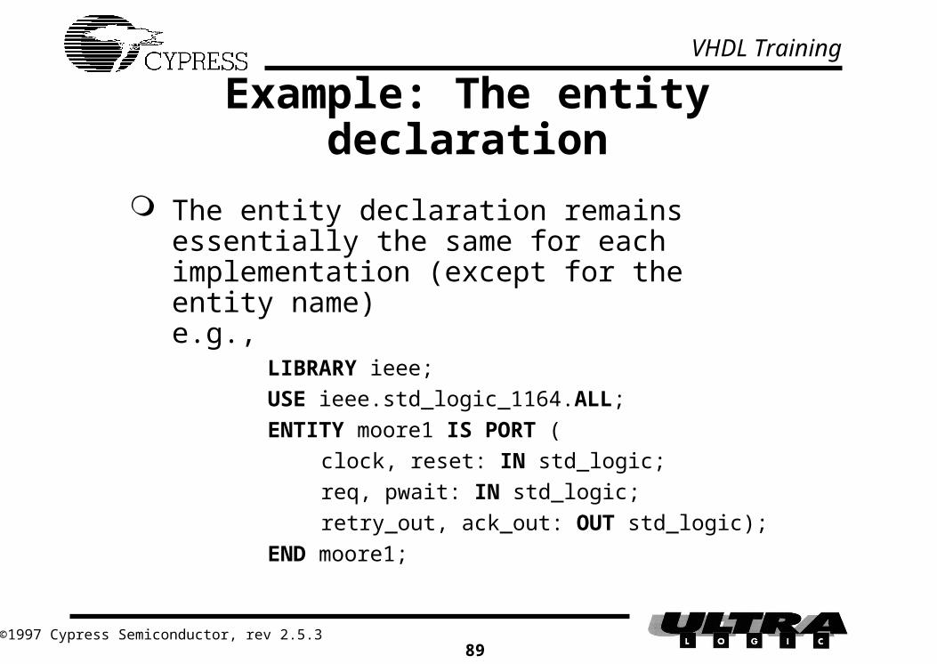
Example: The entity declaration
The entity declaration remains essentially the same for each implementation (except for the entity name)e.g.,
LIBRARY ieee;
USE ieee.std_logic_1164.ALL;
ENTITY moore1 IS PORT (
clock, reset: IN std_logic;
req, pwait: IN std_logic;
retry_out, ack_out: OUT std_logic);
END moore1;
VHDL Training
©1997 Cypress Semiconductor, rev 2.5.390
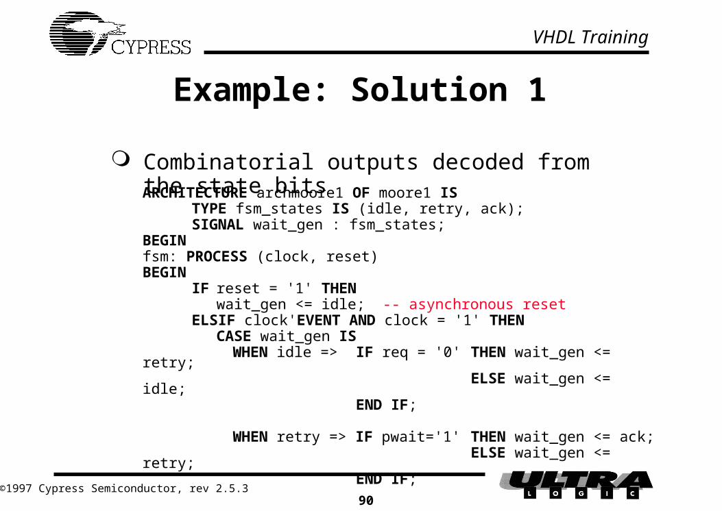
Example: Solution 1
Combinatorial outputs decoded from the state bitsARCHITECTURE archmoore1 OF moore1 IS
TYPE fsm_states IS (idle, retry, ack);SIGNAL wait_gen : fsm_states;
BEGINfsm: PROCESS (clock, reset)BEGIN
IF reset = '1' THENwait_gen <= idle; -- asynchronous reset
ELSIF clock'EVENT AND clock = '1' THENCASE wait_gen ISWHEN idle => IF req = '0' THEN wait_gen <=
retry;ELSE wait_gen <=
idle;END IF;
WHEN retry => IF pwait='1' THEN wait_gen <= ack;ELSE wait_gen <=
retry;END IF;

VHDL Training
©1997 Cypress Semiconductor, rev 2.5.391
Example: Solution 1 (contd.)
WHEN ack => wait_gen <= idle;WHEN OTHERS => wait_gen <= idle;
END CASE;END IF;
END PROCESS fsm;
retry_out <= '1' WHEN (wait_gen = retry) ELSE '0';ack_out <= '1' WHEN (wait_gen = ack) ELSE '0';
END archmoore1;

VHDL Training
©1997 Cypress Semiconductor, rev 2.5.392
Example: Solution 2 Registered outputs decoded from the state bits
ARCHITECTURE archmoore2 OF moore2 IS TYPE fsm_states IS (idle, retry, ack); SIGNAL wait_gen: fsm_states;BEGIN fsm: PROCESS (clock, reset) BEGIN IF reset = '1' THEN wait_gen <= idle; retry_out <= '0'; ack_out <= '0'; ELSIF clock'EVENT AND clock = '1' THEN
retry_out <= '0'; -- a default assignment, could do ack_out too CASE wait_gen IS WHEN idle => IF req = '0' THEN wait_gen <= retry;
retry_out <= '1';ack_out <= '0';
ELSE wait_gen <= idle; ack_out <= '0';
END IF;

VHDL Training
©1997 Cypress Semiconductor, rev 2.5.393
Example: Solution 2 (contd.) WHEN retry => IF pwait = '1' THEN wait_gen <= ack;
ack_out <= '1';ELSE wait_gen <= retry; retry_out <= '1';
ack_out <= '0'; END IF;
WHEN ack => wait_gen <= idle; ack_out <= '0';
WHEN OTHERS => wait_gen <= idle; ack_out <= '0'; -- note must define what
-- happens to ‘ack_out’ END CASE; -- here or a latch will END IF; -- be synthesized to END PROCESS fsm; -- preserve it’s
currentEND archmoore2; -- state

VHDL Training
©1997 Cypress Semiconductor, rev 2.5.394
Example: Solution 3 Outputs encoded within the state bits
ARCHITECTURE archmoore3 OF moore3 IS SIGNAL wait_gen: std_logic_vector(1 DOWNTO 0); CONSTANT idle: std_logic_vector(1 DOWNTO 0) := "00"; CONSTANT retry: std_logic_vector(1 DOWNTO 0) := "01"; CONSTANT ack: std_logic_vector(1 DOWNTO 0) := "10";BEGIN fsm: PROCESS (clock, reset) BEGIN IF reset = '1' THEN wait_gen <= idle; ELSIF clock'EVENT AND clock = '1' THEN
CASE wait_gen IS WHEN idle => IF req = '0' THEN wait_gen <= retry;
ELSE wait_gen <= idle;END IF;

VHDL Training
©1997 Cypress Semiconductor, rev 2.5.395
Example: Solution 3 (contd.)
WHEN retry => IF pwait = '1' THEN wait_gen <= ack;ELSE wait_gen <=
retry;END IF;
WHEN ack => wait_gen <= idle; WHEN OTHERS => wait_gen <= idle;
END CASE; END IF; END PROCESS fsm;
retry_out <= wait_gen(0); ack_out <= wait_gen(1);
END archmoore3;

VHDL Training
©1997 Cypress Semiconductor, rev 2.5.396
State Machines: One-hot Encoding
One state per flip-flop in FPGA-type architectures
• reduces the next state logic
• requires fewer levels of logic cells• enables high-speed state machines (> 100MHz)
in CPLDs
• reduces the number of product terms
• can eliminate ‘expander’ product terms (i.e. reduce delays, and increase operating speed)
• but, uses more macrocells

VHDL Training
©1997 Cypress Semiconductor, rev 2.5.397
Example: One-hot-one Solution
ARCHITECTURE archmoore4 OF moore4 IS
TYPE fsm_states IS (idle, retry, ack);
ATTRIBUTE state_encoding OF fsm_states:TYPE IS one_hot_one;
SIGNAL wait_gen: fsm_states;
BEGIN
fsm: PROCESS (clock, reset)
BEGIN
IF reset = '1' THEN
wait_gen <= idle;
ELSIF clock'EVENT AND clock = '1' THEN
CASE wait_gen IS
WHEN idle => IF req = '0' THEN wait_gen <= retry;
ELSE wait_gen <= idle;
END IF;

VHDL Training
©1997 Cypress Semiconductor, rev 2.5.398
Example: One-hot-one Solution (contd.)
WHEN retry => IF pwait = '1' THEN wait_gen <= ack;ELSE wait_gen <= retry;
END IF; WHEN ack => wait_gen <= idle; WHEN OTHERS => wait_gen <= idle;
END CASE; END IF; END PROCESS fsm;
-- Assign state outputs retry_out <= '1' WHEN (wait_gen = retry) ELSE '0'; ack_out <= '1' WHEN (wait_gen = ack) ELSE '0';
END archmoore4;

VHDL Training
©1997 Cypress Semiconductor, rev 2.5.399
Moore Machines: Summary Outputs decoded from the state bits
• flexibility during the design process• using enumerated types allows automatic state
assignment during compilation Outputs encoded within the state bits
• manual state assignment using constants• the state registers and the outputs are merged• reduces the number of registers• but, may require more product terms
One-Hot encoding• reduces next state decode logic• high speed operation• but, uses more registers

VHDL Training
©1997 Cypress Semiconductor, rev 2.5.3100
Mealy Machines
Outputs may change with a change of state OR with a change of inputs Mealy outputs are non-registered because they
are functions of the present inputs
Inputs
State
Registers
Logic Outputs

VHDL Training
©1997 Cypress Semiconductor, rev 2.5.3101
Example: The Wait State Generator
State diagram:
PWAIT
RESET
(async)
IDLE
0
RETRY
1
REQ
PWAIT
if, ENABLE='0'
RETRY_OUT='1'
REQ

VHDL Training
©1997 Cypress Semiconductor, rev 2.5.3102
Example: Mealy Machine SolutionARCHITECTURE archmealy1 OF mealy1 IS TYPE fsm_states IS (idle, retry); SIGNAL wait_gen: fsm_states;BEGIN fsm: PROCESS (clock, reset) BEGIN IF reset = '1' THEN wait_gen <= idle; ELSIF clock'EVENT AND clock = '1' THEN CASE wait_gen IS WHEN idle => IF req = '0' THEN wait_gen <= retry;
ELSE wait_gen <= idle;END IF;
WHEN retry => IF pwait = '1' THEN wait_gen <= idle;ELSE wait_gen <= retry;
END IF; WHEN OTHERS => wait_gen <= idle;
END CASE; END IF; END PROCESS fsm; retry_out <= '1' WHEN (wait_gen = retry AND enable='0') ELSE '0';END archmealy1;

VHDL Training
©1997 Cypress Semiconductor, rev 2.5.3103
Exercise #5 Design a state machine to implement the function
shown below:
hold extendsamplePOS
POS
RESET
RESET
if, busy='0'
track='1'clear='0'
track='1'

VHDL Training
©1997 Cypress Semiconductor, rev 2.5.3104
Exercise #5: SolutionLIBRARY ieee;USE ieee.std_logic_1164.ALL;ENTITY ex5 IS PORT (
clock, pos, busy, reset: IN std_logic;clear, track: OUT std_logic);
END ex5;
ARCHITECTURE archex5 OF ex5 ISTYPE states IS (hold, sample, extend);ATTRIBUTE state_encoding OF states:TYPE IS one_hot_one;SIGNAL fsm: states;
BEGINclear <= '0' WHEN fsm = sample ELSE '1';track <= '1' WHEN (fsm = sample) OR(fsm = extend AND busy = '0') ELSE '0';

VHDL Training
©1997 Cypress Semiconductor, rev 2.5.3105
Exercise #5: Solution (contd.)
sync: PROCESS (clock) BEGIN
IF clock'EVENT AND clock = '1' THENIF reset = '1' THEN
fsm <= hold; -- synchronous resetELSE
CASE fsm ISWHEN hold => IF pos = '0'
THEN fsm <= sample;ELSE fsm <= hold;END IF;
WHEN sample => fsm <= extend;WHEN extend => fsm <= hold;WHEN OTHERS => fsm <= hold;
END CASE;END IF; -- reset = '1'
END IF; -- clk'EVENT AND clk = '1' END PROCESS sync;END archex5;

VHDL Training
©1997 Cypress Semiconductor, rev 2.5.3106
Hierarchical design methodology
Advantages: Allows the re-use of common building blocks Components (VHDL models or schematic symbols)
can be created, tested and held for later use Smaller components can be more easily integrated
with other blocks Designs are more readable Designs are more portable The design task can be split among several members
of a team

VHDL Training
©1997 Cypress Semiconductor, rev 2.5.3107
Hierarchy decomposition
A VHDL hierarchy is composed of COMPONENTs
• declarations of VHDL models which can be instantiated (placed) within other models
PACKAGEs
• a collection of one or more COMPONENT (and other) declarations

VHDL Training
©1997 Cypress Semiconductor, rev 2.5.3108
Packages and hierarchical designs Packages contain components, types, and/or subtypes
which can be used in other designs Components are entity/architecture pairs with component
declarations Designs that make use of components or types in packages
must include a USE clause, e.g.,
USE WORK.my_package.ALL; The above allows the VHDL code to instantiate all
components/types in my_package
USE WORK.my_package.cnt4; The above allows the VHDL code to instantiate only
the cnt4 components in my_package

VHDL Training
©1997 Cypress Semiconductor, rev 2.5.3109
Packages: How it all fits together
b
selmux2to1
a
c
c
b
mux2to1a
sel• symbol
• component
• schematic
• entity/architecture
• library
• package
• schematic
• entity/architecture
r
toplevel
q
s
c
b
mux2to1a
sel
i t
p
VHDL Training
©1997 Cypress Semiconductor, rev 2.5.3110
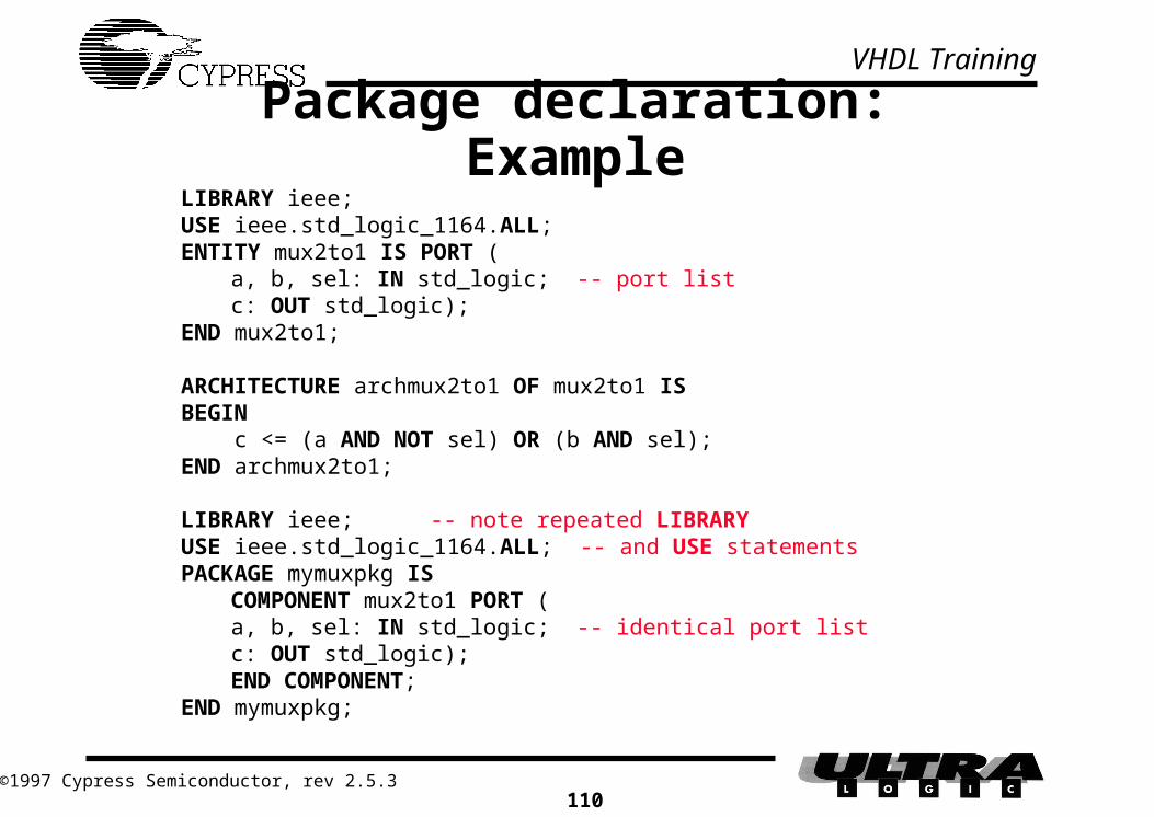
Package declaration: ExampleLIBRARY ieee;USE ieee.std_logic_1164.ALL;ENTITY mux2to1 IS PORT (
a, b, sel: IN std_logic; -- port listc: OUT std_logic);
END mux2to1;
ARCHITECTURE archmux2to1 OF mux2to1 ISBEGIN c <= (a AND NOT sel) OR (b AND sel);END archmux2to1;
LIBRARY ieee; -- note repeated LIBRARYUSE ieee.std_logic_1164.ALL; -- and USE statementsPACKAGE mymuxpkg IS
COMPONENT mux2to1 PORT (a, b, sel: IN std_logic; -- identical port listc: OUT std_logic);
END COMPONENT;END mymuxpkg;

VHDL Training
©1997 Cypress Semiconductor, rev 2.5.3111
Hierarchical design: Example Signals are connected via a PORT MAP that associates signals with the
component's I/O Port map association can be either explicit (named) or implicit (positional)
LIBRARY ieee;USE ieee.std_logic_1164.ALL;ENTITY toplevel IS PORT (s: IN std_logic; p, q, r: IN std_logic_vector(2 DOWNTO 0);
t: OUT std_logic_vector(2 DOWNTO 0));END toplevel;USE WORK.mymuxpkg.ALL;ARCHITECTURE archtoplevel OF toplevel IS
SIGNAL i: std_logic_vector(2 DOWNTO 0);BEGIN
m0: mux2to1 PORT MAP (a=>i(2), b=>r(0), sel=>s, c=>t(0));m1: mux2to1 PORT MAP (c=>t(1), b=>r(1), a=>i(1), sel=>s);m2: mux2to1 PORT MAP (i(0), r(2), s, t(2));i <= p AND NOT q;
END archtoplevel;Positional Association
Named Association

VHDL Training
©1997 Cypress Semiconductor, rev 2.5.3112
Exercise #6: The Design
UPCNT
8
4 (LSB)
4 (MSB)
8
ENABLE
LOAD
DATA
CLOCK
TEST
OE
RESET
DECODER
8
8
8MUX
MUX 8
DECODER
DECODER

VHDL Training
©1997 Cypress Semiconductor, rev 2.5.3113
Exercise #6
Write a hierarchical VHDL description of the previous schematic which instantiates all of the components shown in the design entity/architecture given for top-level design package/entity/architecture given for decoder entity/architecture given for counter, write
package The target device is a CY7C371I-143JC Compile and synthesize your design using Warp

VHDL Training
©1997 Cypress Semiconductor, rev 2.5.3114
Exercise #6: dcodepkg.vhd Analogous to mymuxpkg A entity/architecture for a 7-segment display decoder is
provided in the file - ’decoder.vhd’ A package declaration is also provided in the file -
‘dcodepkg.vhd’, e.g.:LIBRARY ieee;
USE ieee.std_logic_1164.ALL;
PACKAGE dcodepkg IS
COMPONENT decoder PORT(
digit: IN std_logic_vector(3 DOWNTO 0);
leds: OUT std_logic_vector(7 DOWNTO 0));
END COMPONENT;
END dcodepkg;

VHDL Training
©1997 Cypress Semiconductor, rev 2.5.3115
Exercise #6: upcnt.vhd Analogous to mux2to1 and archmux2to1 An entity/architecture pair for an 8-bit loadable
counter is provided in the file - ‘upcnt.vhd’ In a separate file create a package declaration for the
counter based on the entity in upcnt.vhd:LIBRARY ieee;
USE ieee.std_logic_1164.ALL;
ENTITY upcnt IS PORT (
clock, load, reset, enable: IN std_logic;
data: IN std_logic_vector(7 DOWNTO 0);
count: OUT std_logic_vector(7 DOWNTO 0));
END upcnt;

VHDL Training
©1997 Cypress Semiconductor, rev 2.5.3116
Exercise #6 top level: - ex6.vhdLIBRARY ieee;USE ieee.std_logic_1164.ALL;ENTITY ex6 IS PORT(
clock, load, enable, test, oe, reset: IN std_logic;data: IN std_logic_vector(7 DOWNTO 0);seg7hi, seg7lo: OUT std_logic_vector(7 DOWNTO 0));
END ex6;USE WORK.upcntpkg.ALL;USE WORK.dcodepkg.ALL;ARCHITECTURE archex6 OF ex6 IS SIGNAL hicode, locode, count: std_logic_vector(7 DOWNTO 0);BEGIN c1: upcnt PORT MAP (clock, load, reset,
enable, data, count); d1: decoder PORT MAP (count(7 DOWNTO 4), hicode); d2: decoder PORT MAP (count(3 DOWNTO 0), locode); seg7hi <= "ZZZZZZZZ" WHEN oe = '0' ELSE
hicode WHEN test = '0' ELSE data; seg7lo <= (OTHERS => 'Z') WHEN oe = '0' ELSE
locode WHEN test = '0' ELSE data;END archex6;

VHDL Training
©1997 Cypress Semiconductor, rev 2.5.3117
Exercise #6: Instructions Write package for the upcounter Add all of the necessary files to the input list, the top-level
file (ex6.vhd) should be last Click-on the Device button to select the target device Highlight the top-level file and Click-on the Set top button
in the Compiler options Except for the file containing the top-level, highlight each
file in turn and Click-on Selected in the Compile box Finally, highlight and then compile the top-level file to
synthesize the design. Smart will compile only files that have been updated since the last compile.

VHDL Training
©1997 Cypress Semiconductor, rev 2.5.3118
Exercise #6: Solution - upcntpkg.vhd
LIBRARY ieee;
USE ieee.std_logic_1164.ALL;
PACKAGE upcntpkg IS
COMPONENT upcnt PORT(
clock, load, reset, enable: IN std_logic;
data: IN std_logic_vector(7 DOWNTO 0);
count: OUT std_logic_vector(7 DOWNTO 0));
END COMPONENT;
END upcntpkg;

VHDL Training
©1997 Cypress Semiconductor, rev 2.5.3119
Creating repetitive structures
e.g., a 32-bit serial to parallel converter:
• • •
reset
si
clock
q(31) q(30) q(29) q(1) q(0)
po(31) po(30) po(29) po(0)po(1)

VHDL Training
©1997 Cypress Semiconductor, rev 2.5.3120
The GENERATE statement Used to specify repetitive or conditional execution of
a set of concurrent statements Useful for instantiating arrays of components
ENTITY sipo IS PORT (clk, reset: IN std_logic;si: IN std_logic;po: BUFFER std_logic_vector(31 DOWNTO 0));
END sipo;USE WORK.rtlpkg.ALL; -- User-defined package containing dsrffARCHITECTURE archsipo OF sipo ISBEGIN
gen: FOR i IN 0 TO 30 GENERATEnxt: dsrff PORT MAP (po(i+1), zero, reset, clk,
po(i));END GENERATE;beg: dsrff PORT MAP (si, zero, reset, clk, po(31));
END archsipo;

VHDL Training
©1997 Cypress Semiconductor, rev 2.5.3121
Multiplexing I/O pins:LIBRARY ieee ;USE ieee.std_logic_1164.ALL;USE WORK.std_arith.all ;ENTITY ldcnt IS PORT (
clk, ld, oe: IN std_logic;count: INOUT std_logic_vector(7 DOWNTO 0));
END ldcnt; ARCHITECTURE archldcnt OF ldcnt IS
SIGNAL int_count: std_logic_vector(7 DOWNTO 0);BEGIN
cnt: PROCESS (clk)BEGIN
IF clk’EVENT AND clk = '1' THENIF ld = '1' THEN int_count <= count; -- count as
"IN"ELSE int_count <= int_count + 1;END IF;
END IF;END PROCESS cnt ;outen: PROCESS (oe, int_count) BEGIN
IF oe = '1' THEN count <= int_count ; -- count as "OUT"
ELSE count <= (OTHERS => 'Z') ; -- count as "OUT"END IF ; -- equivalent to count <= "ZZZZZZZZ"
END PROCESS outen;END archldcnt;

VHDL Training
©1997 Cypress Semiconductor, rev 2.5.3122
Exercise #7 Design a Moore Machine to implement the Output Enable
Controller shown below:
68040
Output
Enable
Controller
DRAM
Controller
DRAM BANK A DRAM BANK B
DRAM BANK DDRAM BANK C

VHDL Training
©1997 Cypress Semiconductor, rev 2.5.3123
Exercise #7: The FSM chart Use the following FSM chart:
IDLE
OE=1111
RESET
CHOOSE
OE=1111
BANK A
OE=1110
BANK B
OE=1101
BANK C
OE=1011
BANK D
OE=0111
EOC EOC EOC
/EOC
RAM
EOC
/RAM
/A3 AND /A2 /A3 AND A2 A3 AND /A2 A3 AND A2

VHDL Training
©1997 Cypress Semiconductor, rev 2.5.3124
Exercise #7: Solution
ENTITY ex7 IS PORT (clk, reset: IN std_logic;ram, eoc: IN std_logic;a3a2 : IN std_logic_vector(1 DOWNTO 0) ;oe : OUT std_logic_vector(3 DOWNTO 0));
END ex7;
ARCHITECTURE archex7 OF ex7 IS
TYPE oe_states IS (idle, choose, banka, bankb, bankc, bankd);ATTRIBUTE state_encoding OF oe_states : TYPE IS gray ;SIGNAL present_state, next_state : oe_states ;SIGNAL oe_out : std_logic_vector(3 DOWNTO 0) ;
BEGIN

VHDL Training
©1997 Cypress Semiconductor, rev 2.5.3125
Exercise #7: Solution (contd.)
fsm: PROCESS (clk)BEGIN
IF clk'EVENT AND clk = '1' THEN IF reset = '1' THEN
next_state <= idle;ELSE
CASE present_state IS WHEN idle => IF ram = '0' THEN next_state <= choose
;ELSE next_state <= idle ;END IF ;
WHEN choose => CASE a3a2 IS
WHEN "00" => next_state <= banka ;WHEN "01" => next_state <= bankb ;WHEN "10" => next_state <= bankc ;WHEN "11" => next_state <= bankd ;WHEN OTHERS => next_state <= banka ;
END CASE ;WHEN banka => IF eoc = '1' THEN next_state <= bankb
;ELSE next_state <= idle ;END IF ;

VHDL Training
©1997 Cypress Semiconductor, rev 2.5.3126
Exercise #7: Solution (contd.)
WHEN bankb => IF eoc = '1' THEN next_state <= bankc ;
ELSE next_state <= idle ;END IF ;
WHEN bankc => IF eoc = '1' THEN next_state <= bankd ;
ELSE next_state <= idle ;END IF ;
WHEN bankd => IF eoc = '1' THEN next_state <= banka ;
ELSE next_state <= idle ;END IF ;
WHEN OTHERS => next_state <= idle;END CASE;
END IF ;END IF;
END PROCESS fsm;

VHDL Training
©1997 Cypress Semiconductor, rev 2.5.3127
Exercise #7: Solution (contd).output_logic: PROCESS (next_state)BEGIN
CASE next_state IS WHEN idle => oe_out <= "1111" ; WHEN choose => oe_out <= "1111" ; WHEN banka => oe_out <= "1110" ; WHEN bankb => oe_out <= "1101" ; WHEN bankc => oe_out <= "1011" ; WHEN bankd => oe_out <= "0111" ;
WHEN OTHERS => oe_out <= "1111" ;END CASE;
END PROCESS output_logic ;
advance_state: PROCESS (clk)BEGIN
IF clk'EVENT AND clk = '1' THENpresent_state <= next_state ;oe <= oe_out ;
END IF;END PROCESS ;
END archex7;

VHDL Training
©1997 Cypress Semiconductor, rev 2.5.3128
VHDL User-defined Attributes
VHDL construct which is used to provide information about VHDL objects such as entities, architectures, types, and signals. user-defined attributes are used as synthesis
directives to the compiler. These include:• state_encoding• enum_encoding• pin_numbers• synthesis_off

VHDL Training
©1997 Cypress Semiconductor, rev 2.5.3129
The state_encoding attribute
This is used to specify the state encoding scheme of the FSMs in a VHDL file.
The default scheme for CPLDs is sequential. Other schemes such as one_hot_zero and gray
encodings are available.
TYPE state_type IS (idle,state1,state2,state3);
ATTRIBUTE state_encoding OF state_type: TYPE IS sequential;

VHDL Training
©1997 Cypress Semiconductor, rev 2.5.3130
The enum_encoding Attribute
Used to specify the exact internal encoding to be use for each value of a user-defined enumerated type.
Overrides state_encoding in same description.
TYPE states IS (idle,state1,state2,state3);
ATTRIBUTE enum_encoding OF states: TYPE IS "11 01 00 10";

VHDL Training
©1997 Cypress Semiconductor, rev 2.5.3131
The pin_numbers attribute
LIBRARY ieee;USE ieee.std_logic_1164.ALL;ENTITY counter IS PORT (
clock, reset: IN std_logic;count: OUT std_logic_vector(3 DOWNTO 0));ATTRIBUTE pin_numbers OF counter:ENTITY IS"clock:13 reset:2" &" count(3):3 count(2):4 count(1):5
count(0):6";END counter;
Used to map the external signals of an entity to the pins on the target device Allows the back-annotation of pin placements
after synthesis, e.g.,

VHDL Training
©1997 Cypress Semiconductor, rev 2.5.3132
The synthesis_off attribute
Controls the flattening and factoring of signals Makes the signal a factoring point
Useful when a signal with a large number of product terms is used in other equations Helpful in cases where substitution causes
unacceptable compile time (due to exponentially increasing CPU and memory requirements)
Achieves more efficient implementation Should only be used on combinatorial equations
Registered equations are natural factoring points

VHDL Training
©1997 Cypress Semiconductor, rev 2.5.3133
synthesis_off: CPLD Example
An 8-bit comparator controlling a 4-bit, 2-to-1 multiplexer
a(3 DOWNTO 0)
b(3 DOWNTO 0)
x(3 DOWNTO 0)
c(7 DOWNTO 0)
d(7 DOWNTO 0)
mux
8-bitcompare

VHDL Training
©1997 Cypress Semiconductor, rev 2.5.3134
Without synthesis_off
Resources used: 1092 product terms, 68 sum splits, 72 macrocells - the comparison is not done on a bit by bit basis
LIBRARY ieee;USE ieee.std_logic_1164.ALL;ENTITY mux IS PORT (
a, b: IN std_logic_vector(3 DOWNTO 0);c, d: IN std_logic_vector(7 DOWNTO 0);x: OUT std_logic_vector(3 DOWNTO 0));
END mux;
ARCHITECTURE archmux OF mux ISBEGIN
x <= a WHEN (c = d) ELSE b;END archmux;
An implementation (without synthesis_off)

VHDL Training
©1997 Cypress Semiconductor, rev 2.5.3135
Comparison: with a 4-bit vectorS_2 = b * c_0 * /d_0 + b * /c_3 * d_3 + b * c_3 * /d_3 + b * /c_2 * d_2 + b * c_2 * /d_2 + b * /c_1 * d_1 + b * c_1 * /d_1 + b * /c_0 * d_0 S_1 = a * c_3 * c_2 * c_1 * /c_0 * d_3 * d_2 * d_1 * /d_0 + a * /c_3 * c_2 * c_1 * /c_0 * /d_3 * d_2 * d_1 * /d_0 + a * c_3 * /c_2 * c_1 * /c_0 * d_3 * /d_2 * d_1 * /d_0 + a * /c_3 * /c_2 * c_1 * /c_0 * /d_3 * /d_2 * d_1 * /d_0 + a * c_3 * c_2 * /c_1 * /c_0 * d_3 * d_2 * /d_1 * /d_0 + a * /c_3 * c_2 * /c_1 * /c_0 * /d_3 * d_2 * /d_1 * /d_0 + a * c_3 * /c_2 * /c_1 * /c_0 * d_3 * /d_2 * /d_1 * /d_0 + a * /c_3 * /c_2 * /c_1 * /c_0 * /d_3 * /d_2 * /d_1 * /d_0 + a * c_3 * c_2 * c_1 * c_0 * d_3 * d_2 * d_1 * d_0 + a * /c_3 * c_2 * c_1 * c_0 * /d_3 * d_2 * d_1 * d_0 + a * c_3 * /c_2 * c_1 * c_0 * d_3 * /d_2 * d_1 * d_0 + a * /c_3 * /c_2 * c_1 * c_0 * /d_3 * /d_2 * d_1 * d_0 + a * c_3 * c_2 * /c_1 * c_0 * d_3 * d_2 * /d_1 * d_0 + a * /c_3 * c_2 * /c_1 * c_0 * /d_3 * d_2 * /d_1 * d_0 + a * c_3 * /c_2 * /c_1 * c_0 * d_3 * /d_2 * /d_1 * d_0 + a * /c_3 * /c_2 * /c_1 * c_0 * /d_3 * /d_2 * /d_1 * d_0 /x0 = /S_1.CMB * /S_2.CMB

VHDL Training
©1997 Cypress Semiconductor, rev 2.5.3136
With synthesis_off
Resources used: 24 product terms, 1 partial result, 5 macrocells
LIBRARY ieee;USE ieee.std_logic_1164.ALL;ENTITY mux IS PORT (
a, b: IN std_logic_vector(3 DOWNTO 0);c, d: IN std_logic_vector(7 DOWNTO 0);x: OUT std_logic_vector(3 DOWNTO 0));
END mux;
ARCHITECTURE archmux OF mux ISSIGNAL sel: std_logic;ATTRIBUTE synthesis_off OF sel:SIGNAL is TRUE;
BEGINsel <= '1' WHEN (c = d) ELSE '0';x <= a WHEN (sel = '1') ELSE b;
END archmux;
A better implementation (with synthesis_off)

VHDL Training
©1997 Cypress Semiconductor, rev 2.5.3137
Results with synthesis_off
DESIGN EQUATIONS
x_3 = b_3 * /sel.CMB + a_3 * sel.CMB
x_2 = /sel.CMB * b_2 + sel.CMB * a_2
x_1 = /sel.CMB * b_1 + sel.CMB * a_1
x_0 = /sel.CMB * b_0 + sel.CMB * a_0
/sel = c_0 * /d_0 + /c_0 * d_0 + c_1 * /d_1 + /c_1 * d_1 + c_2 * /d_2 + /c_2 * d_2 + c_3 * /d_3 + /c_3 * d_3 + c_4 * /d_4 + /c_4 * d_4 + c_5 * /d_5 + /c_5 * d_5 + c_6 * /d_6 + /c_6 * d_6 + c_7 * /d_7 + /c_7 * d_7

VHDL Training
©1997 Cypress Semiconductor, rev 2.5.3138
CAE Bolt-in Tools
Viewlogic Workview Plus/Powerview/WorkView Office (Q1) Mentor (CY3144), Cadence (Q3)
Synthesis Tools
Synopsys (Q2), Exemplar PLD Development Tools
Data I/O Abel 4/5/6 and Synario, MINC, CUPL, LOG/iC, OrCAD PLD
Simulation Tools
LMG SmartModels All VHDL and Verilog Simulators (with timing)
Third Party Tool Support