vhdl-10 and 11
9
PROGRAMME NO.10 AIM- To design a D – flip flop CODE- Following is the VHDL code for simulation of D flip flop library IEEE; use IEEE.STD_LOGIC_1164.ALL; entity D_FF is Port ( rst : in STD_LOGIC; d : in STD_LOGIC; clk : in STD_LOGIC; q : out STD_LOGIC); end D_FF; architecture Behavioral of D_FF is begin process(clk,rst) begin q <=’0’; if( rst = '1') then q <='0'; elsif( clk'EVENT and clk ='1') then q <= d; end if; end process; end Behavioral;
-
Upload
ankit-goel -
Category
Documents
-
view
213 -
download
0
Transcript of vhdl-10 and 11
PROGRAMME NO.10
AIM- To design a D – flip flop
CODE- Following is the VHDL code for simulation of D flip flop
library IEEE;use IEEE.STD_LOGIC_1164.ALL;
entity D_FF isPort ( rst : in STD_LOGIC;
d : in STD_LOGIC; clk : in STD_LOGIC;
q : out STD_LOGIC);
end D_FF;
architecture Behavioral of D_FF is
begin
process(clk,rst)begin
q <=’0’;if( rst = '1') then
q <='0';elsif( clk'EVENT and clk ='1') then
q <= d;end if;
end process;
end Behavioral;

VHDL TEST BENCH FILE-
LIBRARY ieee;USE ieee.std_logic_1164.ALL; -- Uncomment the following library declaration if using-- arithmetic functions with Signed or Unsigned values--USE ieee.numeric_std.ALL; ENTITY D_FF_tb ISEND D_FF_tb; ARCHITECTURE behavior OF D_FF_tb IS -- Component Declaration for the Unit Under Test (UUT) COMPONENT D_FF PORT( rst : IN std_logic; d : IN std_logic; clk : IN std_logic; q : OUT std_logic ); END COMPONENT;
--Inputs signal rst : std_logic := '0'; signal d : std_logic := '0'; signal clk : std_logic := '0';
--Outputs signal q : std_logic;
-- Clock period definitions constant clk_period : time := 2ps; BEGIN
-- Instantiate the Unit Under Test (UUT) uut: D_FF PORT MAP ( rst => rst, d => d, clk => clk, q => q );
-- Clock process definitions clk_process :process
beginclk <= '0';wait for clk_period/2;clk <= '1';wait for clk_period/2;
end process;
-- Stimulus process stim_proc: process begin
d <= '0'; wait for 4ps;
d <= '1';wait for 4ps;
rst <= '1'; wait for 4ps;
end process;
END;
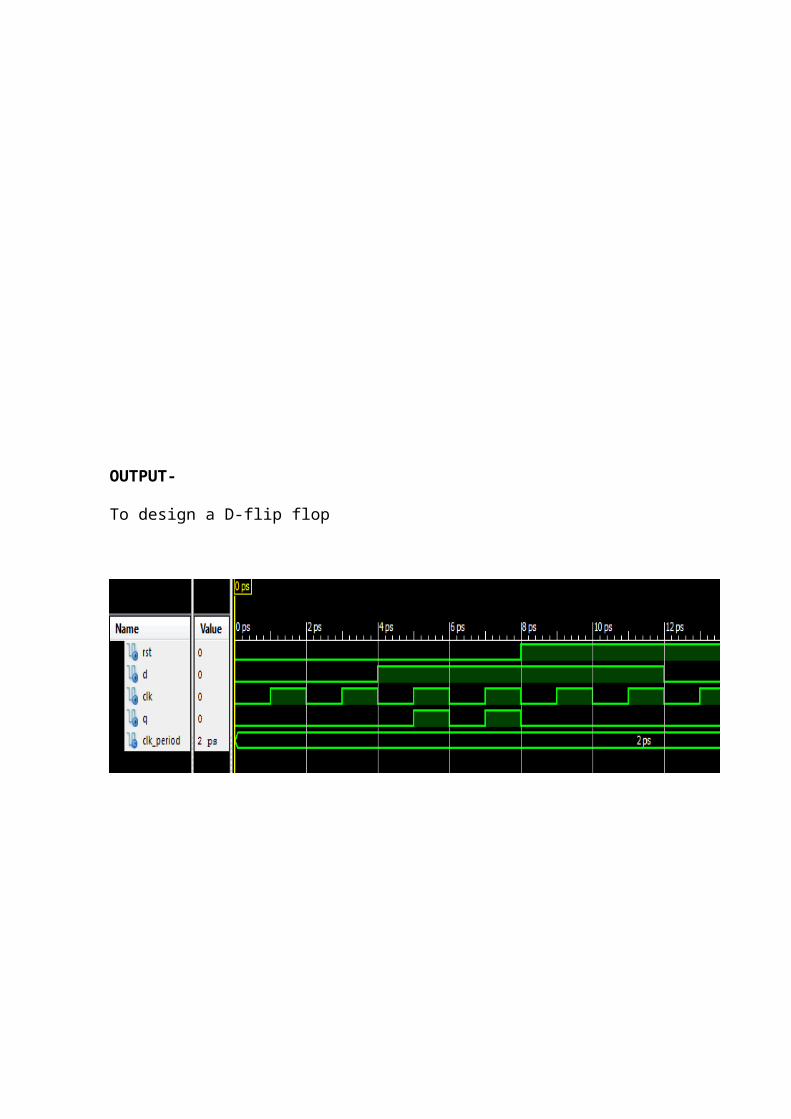
OUTPUT-
To design a D-flip flop

PROGRAMME NO.11
AIM- To design 8x1 Multiplexer
CODE-Following is the VHDL code for simulation of 8x1 Multiplexer
library IEEE;use IEEE.STD_LOGIC_1164.ALL;
-- Uncomment the following library declaration if using-- arithmetic functions with Signed or Unsigned values--use IEEE.NUMERIC_STD.ALL;
-- Uncomment the following library declaration if instantiating-- any Xilinx primitives in this code.--library UNISIM;--use UNISIM.VComponents.all;
entity multiplexer is Port ( I : in STD_LOGIC_VECTOR (7 downto 0); O : out STD_LOGIC; Sel : in STD_LOGIC_VECTOR (2 downto 0));end multiplexer;
architecture behavorial of multiplexer is
begin
with Sel select O <=I(0) when "000",I(1) when "001",I(2) when "010",I(3) when "011",I(4) when "100",I(5) when "101",I(6) when "110",I(7) when "111",'0' when others;
end behavorial;

VHDL TEST BENCH FILE-
LIBRARY ieee;USE ieee.std_logic_1164.ALL; -- Uncomment the following library declaration if using-- arithmetic functions with Signed or Unsigned values--USE ieee.numeric_std.ALL; ENTITY multiplexer_tb ISEND multiplexer_tb; ARCHITECTURE behavior OF multiplexer_tb IS -- Component Declaration for the Unit Under Test (UUT) COMPONENT multiplexer PORT( I : IN std_logic_vector(7 downto 0); O : OUT std_logic; Sel : IN std_logic_vector(2 downto 0) ); END COMPONENT;
--Inputs signal I : std_logic_vector(7 downto 0) := (others => '0'); signal Sel : std_logic_vector(2 downto 0) := (others => '0');
--Outputs signal O : std_logic; -- No clocks detected in port list. Replace <clock> below with -- appropriate port name constant period : time := 1ps; BEGIN
-- Instantiate the Unit Under Test (UUT) uut: multiplexer PORT MAP ( I => I, O => O, Sel => Sel );
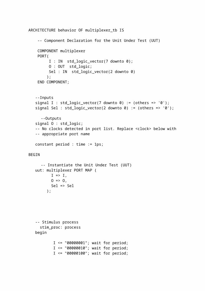
-- Stimulus process stim_proc: process begin
I <= "00000001"; wait for period;I <= "00000010"; wait for period;I <= "00000100"; wait for period;I <= "00001000"; wait for period;I <= "00010000"; wait for period;I <= "00100000"; wait for period;I <= "01000000"; wait for period;I <= "10000000"; wait for period;
end process;
select_process: process begin
Sel <= "000"; wait for period;Sel <= "001"; wait for period;Sel <= "010"; wait for period;Sel <= "011"; wait for period;Sel <= "100"; wait for period;Sel <= "101"; wait for period;Sel <= "110"; wait for period;Sel <= "111"; wait for period;
end process;END;

OUTPUT-
To design 8x1 multiplexer