VGA System Services How to use Linux’s ‘vm86()’ system-call to access the video ROM-BIOS...
25
VGA System Services How to use Linux’s ‘vm86()’ system-call to access the video ROM-BIOS functions
-
date post
21-Dec-2015 -
Category
Documents
-
view
219 -
download
2
Transcript of VGA System Services How to use Linux’s ‘vm86()’ system-call to access the video ROM-BIOS...
VGA System Services
How to use Linux’s ‘vm86()’ system-call to access the video
ROM-BIOS functions
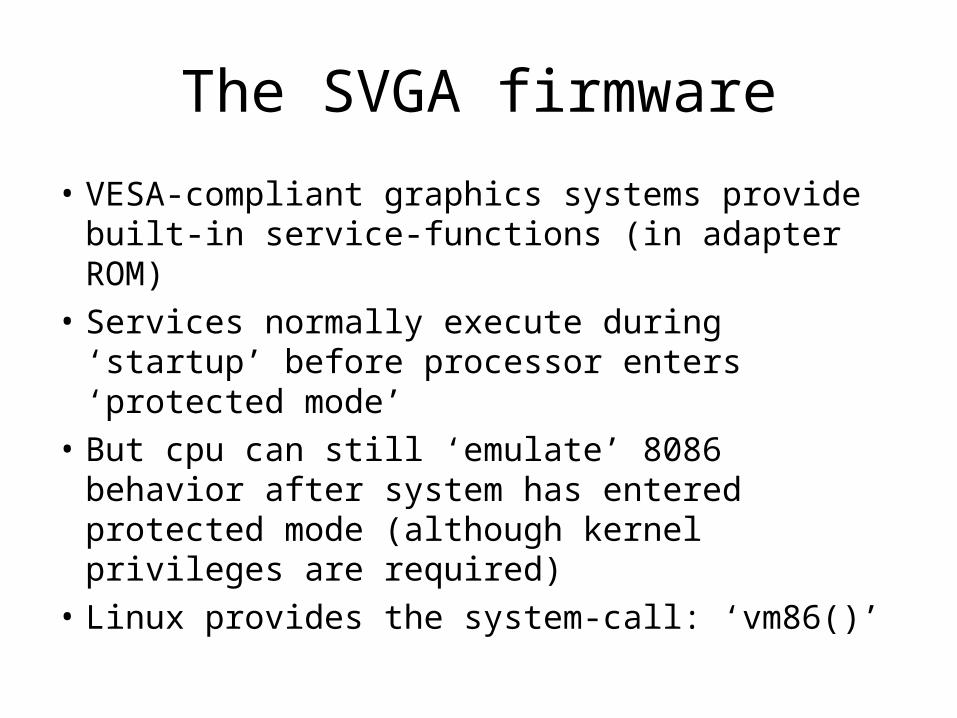
The SVGA firmware
• VESA-compliant graphics systems provide built-in service-functions (in adapter ROM)
• Services normally execute during ‘startup’ before processor enters ‘protected mode’
• But cpu can still ‘emulate’ 8086 behavior after system has entered protected mode (although kernel privileges are required)
• Linux provides the system-call: ‘vm86()’

8086
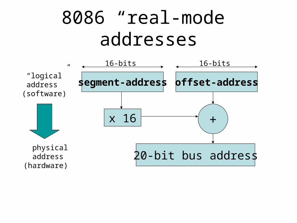
• At startup, the Pentium operates like 8086:– Physical memory is directly addressable– But memory addresses are only 20-bits
• CPU builds address from a pair of values:– Segment-address (16-bits) in special register– Offset-address (16-bits) in register or memory
• Formula: address = (segment<<4) + offset
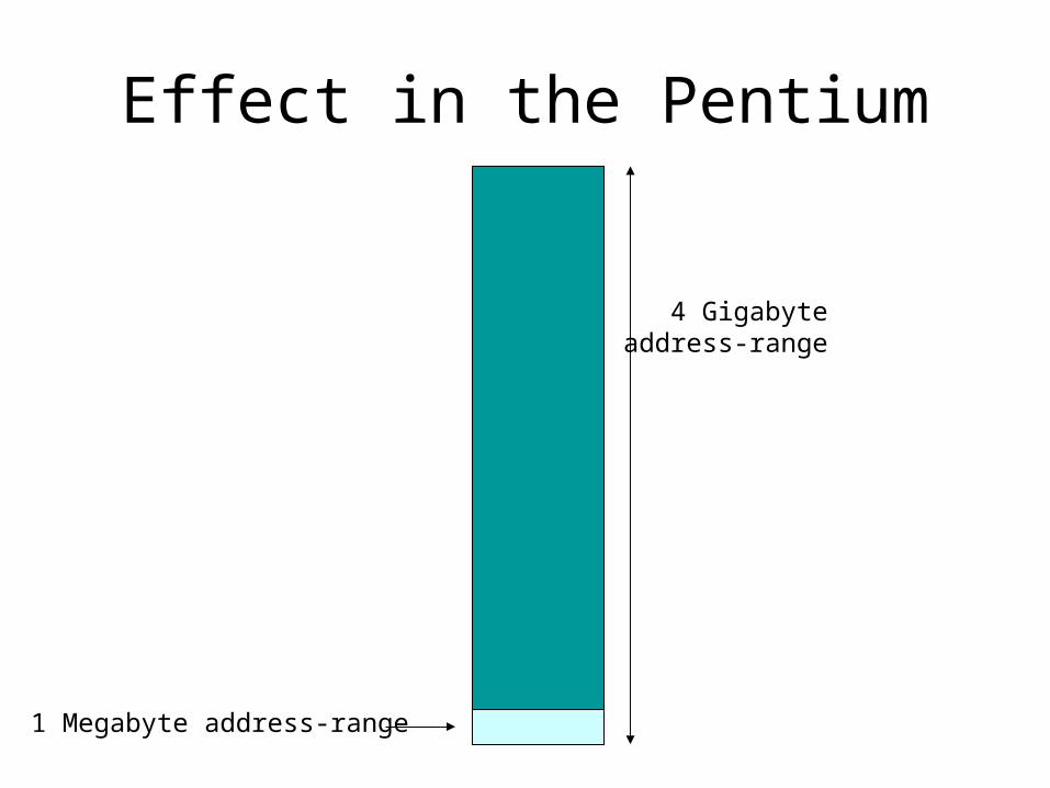
• Address-range: 220 = 1,048,576 bytes
8086 “real-mode” addresses
segment-address offset-address
20-bit bus address
+x 16
“logical” address(software)
physical address(hardware)
16-bits 16-bits
Effect in the Pentium
4 Gigabyteaddress-range
1 Megabyte address-range

“Protected” Mode
• At startup, the Pentium essentially IS an 8086 processor (operates in “real mode”):– It addresses physical memory like an 8086– It operates without any privilege-restrictions
• But after building essential data-structures the Pentium switches to “protected” mode and turns on “virtual” memory-addressing:– To supports the execution of multiple tasks – To impose restrictions on memory access

Pentium can ‘emulate’ 8086
• Even after it enters “protected” mode, the Pentium can still ‘emulate’ 8086 behavior
• This works by creating a ‘virtual 8086’ cpu represented by a special data-structure in memory and triggered by a special opcode
• But a few 8086 instructions aren’t allowed (if they could perhaps interfere with other tasks):– Device i/o: IN and OUT– Interrupts: CLI / STI, PUSHF / POPF, INT-n / IRET– Execution: HLT
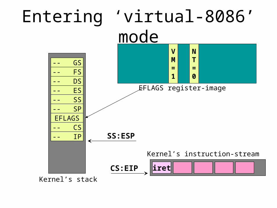
Entering ‘virtual-8086’ mode
-- GS-- FS-- DS-- ES-- SS-- SP
EFLAGS-- CS-- IP
Kernel’s stack
SS:ESP
iretCS:EIP
Kernel’s instruction-stream
NT=0
VM=1
EFLAGS register-image
Leaving “virtual-8086” mode
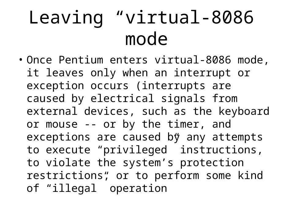
• Once Pentium enters virtual-8086 mode, it leaves only when an interrupt or exception occurs (interrupts are caused by electrical signals from external devices, such as the keyboard or mouse -- or by the timer, and exceptions are caused by any attempts to execute “privileged” instructions, to violate the system’s protection restrictions, or to perform some kind of “illegal” operation
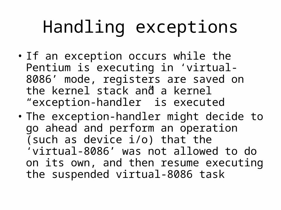
Handling exceptions
• If an exception occurs while the Pentium is executing in ‘virtual-8086’ mode, registers are saved on the kernel stack and a kernel “exception-handler” is executed
• The exception-handler might decide to go ahead and perform an operation (such as device i/o) that the ‘virtual-8086’ was not allowed to do on its own, and then resume executing the suspended virtual-8086 task
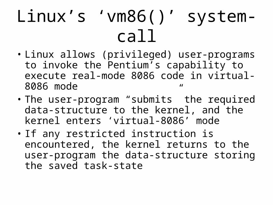
Linux’s ‘vm86()’ system-call
• Linux allows (privileged) user-programs to invoke the Pentium’s capability to execute real-mode 8086 code in virtual-8086 mode
• The user-program “submits” the required data-structure to the kernel, and the kernel enters ‘virtual-8086’ mode
• If any restricted instruction is encountered, the kernel returns to the user-program the data-structure storing the saved task-state
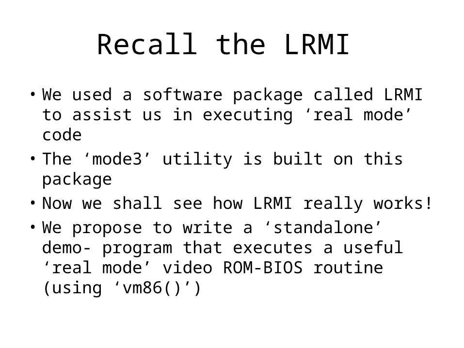
Recall the LRMI
• We used a software package called LRMI to assist us in executing ‘real mode’ code
• The ‘mode3’ utility is built on this package
• Now we shall see how LRMI really works!
• We propose to write a ‘standalone’ demo- program that executes a useful ‘real mode’ video ROM-BIOS routine (using ‘vm86()’)

Linux Device-Drivers
• We will need a way to ‘map’ certain special memory-regions into the user address-space
• These regions must be mapped to addresses that an 8086 processor could access (i.e., must be in bottom one-megabyte of virtual memory)
• Linux normally “maps” nothing else there • We’ll need device-drivers to perform mappings:
/dev/zero (This is a standard part of Linux)
/dev/dos (This is a ‘custom’ driver we built)
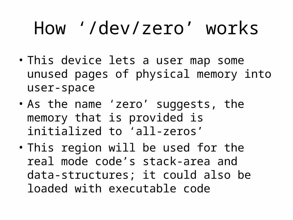
How ‘/dev/zero’ works
• This device lets a user map some unused pages of physical memory into user-space
• As the name ‘zero’ suggests, the memory that is provided is initialized to ‘all-zeros’
• This region will be used for the real mode code’s stack-area and data-structures; it could also be loaded with executable code
How ‘/dev/dos’ works
• This device lets a user map conventional areas of initialized system memory into a user’s virtual address-space (such as the real-mode Interrupt Vector Table and the ROM-BIOS Data Area); and also the VGA system firmware!
• There’s a similar device (‘/dev/mem’) that is a standard part of Linux, but it requires ‘root’ privileges for writing; so we substitute our own device-driver to avoid that ‘hassle’.
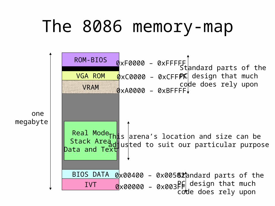
The 8086 memory-map
onemegabyte
ROM-BIOS
VRAM
VGA ROM
IVT
BIOS DATA
Real ModeStack Area
Data and Text
0xA0000 – 0xBFFFF
0xC0000 – 0xCFFFF
0xF0000 – 0xFFFFF
0x00000 – 0x003FF
0x00400 – 0x00502
This arena’s location and size can beadjusted to suit our particular purpose
Standard parts of thePC design that muchcode does rely upon
Standard parts of thePC design that muchcode does rely upon
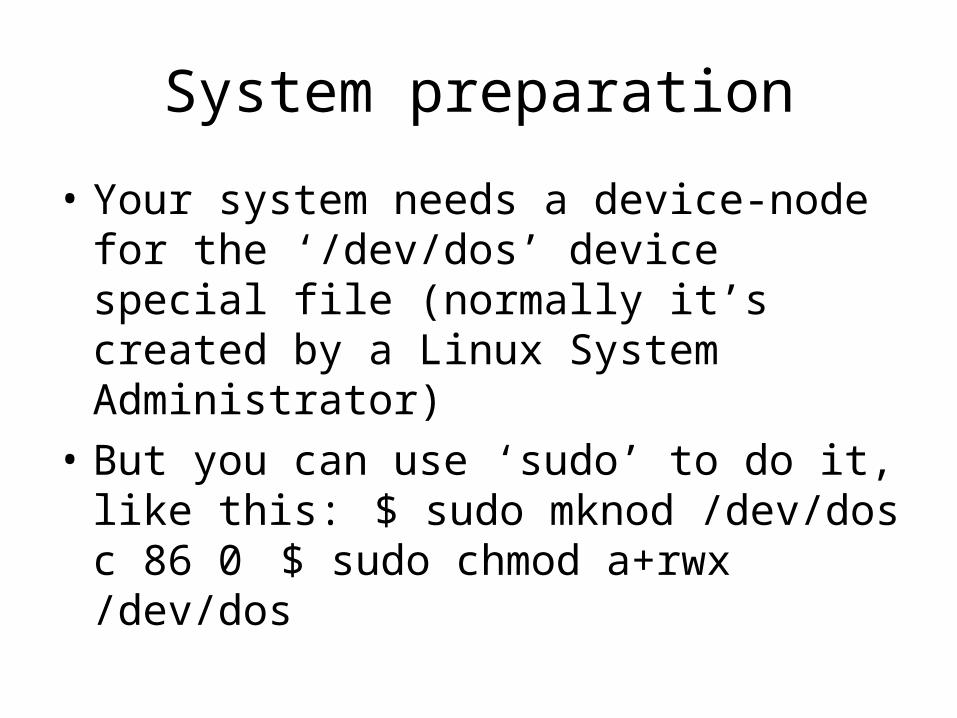
System preparation
• Your system needs a device-node for the ‘/dev/dos’ device special file (normally it’s created by a Linux System Administrator)
• But you can use ‘sudo’ to do it, like this: $ sudo mknod /dev/dos c 86 0 $ sudo chmod a+rwx /dev/dos

The actual program-code
• Use header-file: #include <sys/vm86.h>
• Declare object: struct vm86_struct vm;
• Map in the necessary memory-regions
• Initialize memory-areas as appropriate
• Initialize register-images in ‘vm86_struct’
• Call kernel: int result = vm86( &vm );
• Emulate any input and output instructions
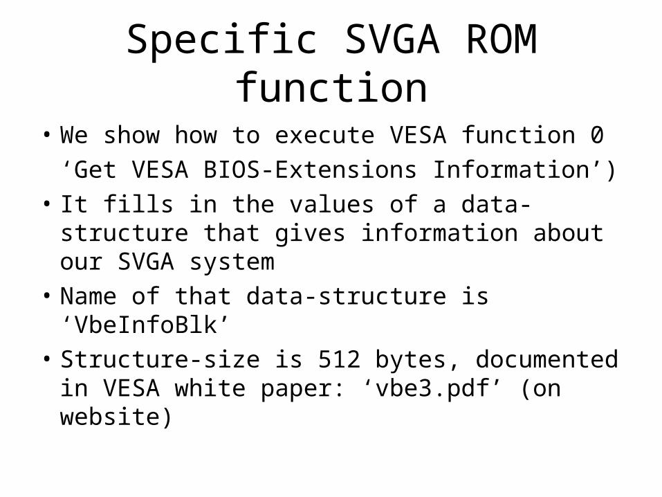
Specific SVGA ROM function
• We show how to execute VESA function 0
‘Get VESA BIOS-Extensions Information’)
• It fills in the values of a data-structure that gives information about our SVGA system
• Name of that data-structure is ‘VbeInfoBlk’
• Structure-size is 512 bytes, documented in VESA white paper: ‘vbe3.pdf’ (on website)
The calling convention
• VESA functions are designed to be called from an 8086 assembly-language program that is executing in real mode (i.e., startup)
• Register AX is loaded with value 0x0F00• Registers ES:DI are loaded with address
(segment:offset) of the memory-block that is to be filled in (512 bytes), initialized with 4-character string “VBE2”
• Then software interrupt 0x10 is executed

Software interrupt instruction
• The effect of executing ‘int-0x10’ is to transfer control to a function in ROM
• The entry-point to that function was stored in the (real-mode) Interrupt Vector Table by the ROM-BIOS startup code
• We can extract that entry-point address and use its pair of values as initial values for registers CS and IP in our virtual 8086

Emulating ‘in’ and ‘out’
• Whenever an ‘in’ or ‘out’ instruction is encountered in ‘virtual-8086’ mode, our application can do an ‘emulation’
• We decode the instruction and execute it on behalf of the virtual-8086 task, and we increment the IP value to “skip” past that ‘in’ or ‘out’ instruction, then we can resume the interrupted virtual-8086 task by calling ‘vm86()’ again, using the adjusted ‘vm’
Stopping the vm86 execution
• We need a way to stop our execution-loop
• We do it using a special 8086 instruction that cannot execute in virtual-8086 mode
• Instead of emulating it, we stop our loop
• Various instructions could serve this aim
• We choose to use the ‘hlt’ instruction
• It’s just 1-byte; its name suggests the idea
Demo-program: ‘vesainfo.cpp’
• We’ve posted source-code for this demo
• It implements the ideas we just discussed
• It prints out the information in ‘VbeInfoBlk’
• It is based on the VESA documentation
• Exercise: You could try modifying our code to perform VESA function 1 (which is quite similar to function 0): it returns information about support for specific display-modes
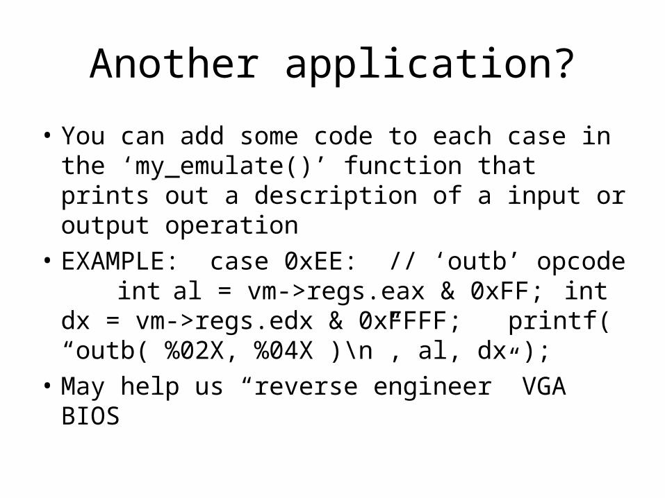
Another application?
• You can add some code to each case in the ‘my_emulate()’ function that prints out a description of a input or output operation
• EXAMPLE: case 0xEE: // ‘outb’ opcodeint al = vm->regs.eax & 0xFF;int dx = vm->regs.edx & 0xFFFF;printf( “outb( %02X, %04X )\n”, al, dx );
• May help us “reverse engineer” VGA BIOS