VESA Display Stream Compression (DSC) Standard · 2019-10-22 · a mobile application host...
145
VESA Display Stream Compression (DSC) Standard UNAUTHORIZED DISTRIBUTION PROHIBITED Version 1.2a Copyright © 2014 – 2017 Video Electronics Standards Association. All rights reserved. Page 1 of 145 VESA Display Stream Compression (DSC) Standard www.vesa.org Version 1.2a 18 January, 2017 Purpose The purpose of this document is to specify the VESA ® Display Stream Compression (DSC) Standard. Summary The DSC Standard is a specification of the algorithms used for compressing and decompressing image display streams, including the specification of the syntax and semantics of the compressed video bitstream. DSC is designed for real-time systems, with real-time compression, transmission, decompression, and display. DSC specifies the compressed video bitstream. DSC does not specify a Transport Layer. Practical systems that use DSC must follow a suitable transport specification in which the Transport Layer conveys DSC streams, from source to destination. DSC is a compression and decompression standard for display streams between two distinct devices, either from one box level product to another, or from one chip to another within a box-level product, by way of a display stream interface. Display stream interfaces that could apply this standard include those between a mobile application host processor and display panel module, between a computer graphics output and display monitor, or between a consumer electronics source device to a display device, such as a television. Display stream interfaces can be either wired or wireless.
Transcript of VESA Display Stream Compression (DSC) Standard · 2019-10-22 · a mobile application host...

VESA Display Stream Compression (DSC) Standard UNAUTHORIZED DISTRIBUTION PROHIBITED Version 1.2aCopyright © 2014 – 2017 Video Electronics Standards Association. All rights reserved. Page 1 of 145
VESA Display Stream Compression (DSC) Standard
www.vesa.org
Version 1.2a
18 January, 2017
Purpose
The purpose of this document is to specify the VESA® Display Stream Compression (DSC) Standard.
SummaryThe DSC Standard is a specification of the algorithms used for compressing and decompressing image display streams, including the specification of the syntax and semantics of the compressed video bitstream. DSC is designed for real-time systems, with real-time compression, transmission, decompression, and display.
DSC specifies the compressed video bitstream. DSC does not specify a Transport Layer. Practical systems that use DSC must follow a suitable transport specification in which the Transport Layer conveys DSC streams, from source to destination.
DSC is a compression and decompression standard for display streams between two distinct devices, either from one box level product to another, or from one chip to another within a box-level product, by way of a display stream interface. Display stream interfaces that could apply this standard include those between a mobile application host processor and display panel module, between a computer graphics output and display monitor, or between a consumer electronics source device to a display device, such as a television. Display stream interfaces can be either wired or wireless.

Contents
Purpose . . . . . . . . . . . . . . . . . . . . . . . . . . . . . . . . . . . . . . . . . . . . . . . . . . . . . . . . . . . . . . . . . . . . . . . . . . 1
Summary . . . . . . . . . . . . . . . . . . . . . . . . . . . . . . . . . . . . . . . . . . . . . . . . . . . . . . . . . . . . . . . . . . . . . . . . . 1Intellectual Property . . . . . . . . . . . . . . . . . . . . . . . . . . . . . . . . . . . . . . . . . . . . . . . . . . . . . . . . . . .9Trademarks . . . . . . . . . . . . . . . . . . . . . . . . . . . . . . . . . . . . . . . . . . . . . . . . . . . . . . . . . . . . . . . . . .9Patents . . . . . . . . . . . . . . . . . . . . . . . . . . . . . . . . . . . . . . . . . . . . . . . . . . . . . . . . . . . . . . . . . . . . . .9Support for this Standard. . . . . . . . . . . . . . . . . . . . . . . . . . . . . . . . . . . . . . . . . . . . . . . . . . . . . . .11Acknowledgments . . . . . . . . . . . . . . . . . . . . . . . . . . . . . . . . . . . . . . . . . . . . . . . . . . . . . . . . . . . .11Revision History . . . . . . . . . . . . . . . . . . . . . . . . . . . . . . . . . . . . . . . . . . . . . . . . . . . . . . . . . . . . .13
Section 1 Introduction . . . . . . . . . . . . . . . . . . . . . . . . . . . . . . . . . . . . . . . . . . . . . . . . . . . . . . . . 151.1 Document Organization . . . . . . . . . . . . . . . . . . . . . . . . . . . . . . . . . . . . . . . . . . . . . . . . .151.2 Display Stream Compression Objectives. . . . . . . . . . . . . . . . . . . . . . . . . . . . . . . . . . . .161.3 Display Stream Compression Versions . . . . . . . . . . . . . . . . . . . . . . . . . . . . . . . . . . . . .161.4 Acronyms, Initialisms, and Abbreviations. . . . . . . . . . . . . . . . . . . . . . . . . . . . . . . . . . .171.5 Glossary . . . . . . . . . . . . . . . . . . . . . . . . . . . . . . . . . . . . . . . . . . . . . . . . . . . . . . . . . . . . .191.6 Symbols . . . . . . . . . . . . . . . . . . . . . . . . . . . . . . . . . . . . . . . . . . . . . . . . . . . . . . . . . . . . .22
1.6.1 Bit Ordering . . . . . . . . . . . . . . . . . . . . . . . . . . . . . . . . . . . . . . . . . . . . . . . . . . .221.6.2 Functions . . . . . . . . . . . . . . . . . . . . . . . . . . . . . . . . . . . . . . . . . . . . . . . . . . . . . .22
1.7 Conventions . . . . . . . . . . . . . . . . . . . . . . . . . . . . . . . . . . . . . . . . . . . . . . . . . . . . . . . . . .231.8 Reference Documents . . . . . . . . . . . . . . . . . . . . . . . . . . . . . . . . . . . . . . . . . . . . . . . . . .23
Section 2 Requirements (Informative) . . . . . . . . . . . . . . . . . . . . . . . . . . . . . . . . . . . . . . . . . . . 24
Section 3 Theory of Operation (Informative). . . . . . . . . . . . . . . . . . . . . . . . . . . . . . . . . . . . . . 253.1 Overview . . . . . . . . . . . . . . . . . . . . . . . . . . . . . . . . . . . . . . . . . . . . . . . . . . . . . . . . . . . .253.2 Color Space Conversion. . . . . . . . . . . . . . . . . . . . . . . . . . . . . . . . . . . . . . . . . . . . . . . . .303.3 Prediction and Quantization . . . . . . . . . . . . . . . . . . . . . . . . . . . . . . . . . . . . . . . . . . . . . .30
3.3.1 Modified Median-Adaptive Prediction . . . . . . . . . . . . . . . . . . . . . . . . . . . . . . .303.3.2 Block Prediction . . . . . . . . . . . . . . . . . . . . . . . . . . . . . . . . . . . . . . . . . . . . . . . .313.3.3 Midpoint Prediction . . . . . . . . . . . . . . . . . . . . . . . . . . . . . . . . . . . . . . . . . . . . .32
3.4 Indexed Color History . . . . . . . . . . . . . . . . . . . . . . . . . . . . . . . . . . . . . . . . . . . . . . . . . .333.5 Bitstream Construction. . . . . . . . . . . . . . . . . . . . . . . . . . . . . . . . . . . . . . . . . . . . . . . . . .34
3.5.1 Substream Layer . . . . . . . . . . . . . . . . . . . . . . . . . . . . . . . . . . . . . . . . . . . . . . . .343.5.2 Substream Multiplexing . . . . . . . . . . . . . . . . . . . . . . . . . . . . . . . . . . . . . . . . . .36
3.6 Rate Control . . . . . . . . . . . . . . . . . . . . . . . . . . . . . . . . . . . . . . . . . . . . . . . . . . . . . . . . . .383.7 Timing . . . . . . . . . . . . . . . . . . . . . . . . . . . . . . . . . . . . . . . . . . . . . . . . . . . . . . . . . . . . . .39
3.7.1 Hypothetical Reference Decoder-Based Timing Model . . . . . . . . . . . . . . . . . .393.7.2 Constant and Variable Bit Rate Modes. . . . . . . . . . . . . . . . . . . . . . . . . . . . . . .413.7.3 Slices and Timing . . . . . . . . . . . . . . . . . . . . . . . . . . . . . . . . . . . . . . . . . . . . . . .42
3.8 Options for Slices . . . . . . . . . . . . . . . . . . . . . . . . . . . . . . . . . . . . . . . . . . . . . . . . . . . . . .453.9 Slice Multiplexing . . . . . . . . . . . . . . . . . . . . . . . . . . . . . . . . . . . . . . . . . . . . . . . . . . . . .46
VESA Display Stream Compression (DSC) Standard UNAUTHORIZED DISTRIBUTION PROHIBITED Version 1.2aCopyright © 2014 – 2017 Video Electronics Standards Association. All rights reserved. Page 2 of 145
3.10 Differences between DSC v1.1 and DSC v1.2 . . . . . . . . . . . . . . . . . . . . . . . . . . . . . . . .473.10.1 Native 4:2:2 and 4:2:0 Modes . . . . . . . . . . . . . . . . . . . . . . . . . . . . . . . . . . . . . .473.10.2 14- and 16-bits Per Component Support. . . . . . . . . . . . . . . . . . . . . . . . . . . . . .493.10.3 Other Differences . . . . . . . . . . . . . . . . . . . . . . . . . . . . . . . . . . . . . . . . . . . . . . .49
Section 4 Syntax (Normative) . . . . . . . . . . . . . . . . . . . . . . . . . . . . . . . . . . . . . . . . . . . . . . . . . . 504.1 Picture Parameter Set . . . . . . . . . . . . . . . . . . . . . . . . . . . . . . . . . . . . . . . . . . . . . . . . . . .50
4.1.1 Syntax . . . . . . . . . . . . . . . . . . . . . . . . . . . . . . . . . . . . . . . . . . . . . . . . . . . . . . . .504.1.2 Picture Parameter Set Timing . . . . . . . . . . . . . . . . . . . . . . . . . . . . . . . . . . . . . .58
4.2 Picture Syntax . . . . . . . . . . . . . . . . . . . . . . . . . . . . . . . . . . . . . . . . . . . . . . . . . . . . . . . .594.2.1 Picture Syntax Overview. . . . . . . . . . . . . . . . . . . . . . . . . . . . . . . . . . . . . . . . . .594.2.2 Slice Multiplexing in Constant Bit Rate Mode . . . . . . . . . . . . . . . . . . . . . . . . .594.2.3 Slice Multiplexing in Variable Bit Rate Mode . . . . . . . . . . . . . . . . . . . . . . . . .60
4.3 Slice . . . . . . . . . . . . . . . . . . . . . . . . . . . . . . . . . . . . . . . . . . . . . . . . . . . . . . . . . . . . . . . .624.4 Substream Multiplexing . . . . . . . . . . . . . . . . . . . . . . . . . . . . . . . . . . . . . . . . . . . . . . . . .634.5 Substream Syntax. . . . . . . . . . . . . . . . . . . . . . . . . . . . . . . . . . . . . . . . . . . . . . . . . . . . . .65
Section 5 Capability Parameter Set (Informative). . . . . . . . . . . . . . . . . . . . . . . . . . . . . . . . . . 73
Section 6 Encoding Process (Normative) . . . . . . . . . . . . . . . . . . . . . . . . . . . . . . . . . . . . . . . . 746.1 Color Space Conversion. . . . . . . . . . . . . . . . . . . . . . . . . . . . . . . . . . . . . . . . . . . . . . . . .746.2 Slice Padding . . . . . . . . . . . . . . . . . . . . . . . . . . . . . . . . . . . . . . . . . . . . . . . . . . . . . . . . .756.3 Line Storage . . . . . . . . . . . . . . . . . . . . . . . . . . . . . . . . . . . . . . . . . . . . . . . . . . . . . . . . . .756.4 Prediction and Quantization . . . . . . . . . . . . . . . . . . . . . . . . . . . . . . . . . . . . . . . . . . . . . .76
6.4.1 Modified Median-Adaptive Prediction . . . . . . . . . . . . . . . . . . . . . . . . . . . . . . .766.4.2 Block Prediction . . . . . . . . . . . . . . . . . . . . . . . . . . . . . . . . . . . . . . . . . . . . . . . .796.4.3 Midpoint Prediction . . . . . . . . . . . . . . . . . . . . . . . . . . . . . . . . . . . . . . . . . . . . .806.4.4 Prediction Method Decision . . . . . . . . . . . . . . . . . . . . . . . . . . . . . . . . . . . . . . .806.4.5 Quantization . . . . . . . . . . . . . . . . . . . . . . . . . . . . . . . . . . . . . . . . . . . . . . . . . . .836.4.6 Inverse Quantization and Reconstruction . . . . . . . . . . . . . . . . . . . . . . . . . . . . .83
6.5 Indexed Color History . . . . . . . . . . . . . . . . . . . . . . . . . . . . . . . . . . . . . . . . . . . . . . . . . .846.5.1 Pixel History . . . . . . . . . . . . . . . . . . . . . . . . . . . . . . . . . . . . . . . . . . . . . . . . . . .846.5.2 Indexed Color History Updates. . . . . . . . . . . . . . . . . . . . . . . . . . . . . . . . . . . . .866.5.3 Encoder Decisions. . . . . . . . . . . . . . . . . . . . . . . . . . . . . . . . . . . . . . . . . . . . . . .88
6.6 Entropy Encoder. . . . . . . . . . . . . . . . . . . . . . . . . . . . . . . . . . . . . . . . . . . . . . . . . . . . . . .916.6.1 Delta Size Unit-Variable Length Coding . . . . . . . . . . . . . . . . . . . . . . . . . . . . .916.6.2 Indexed Color History Coding . . . . . . . . . . . . . . . . . . . . . . . . . . . . . . . . . . . . .936.6.3 Flatness Signaling . . . . . . . . . . . . . . . . . . . . . . . . . . . . . . . . . . . . . . . . . . . . . . .946.6.4 Outputs to Rate Control . . . . . . . . . . . . . . . . . . . . . . . . . . . . . . . . . . . . . . . . . .94
6.7 Substream Multiplexer . . . . . . . . . . . . . . . . . . . . . . . . . . . . . . . . . . . . . . . . . . . . . . . . . .956.7.1 Balance FIFOs. . . . . . . . . . . . . . . . . . . . . . . . . . . . . . . . . . . . . . . . . . . . . . . . . .956.7.2 Multiplexer . . . . . . . . . . . . . . . . . . . . . . . . . . . . . . . . . . . . . . . . . . . . . . . . . . . .966.7.3 Decoder Model . . . . . . . . . . . . . . . . . . . . . . . . . . . . . . . . . . . . . . . . . . . . . . . . .966.7.4 End of Slice . . . . . . . . . . . . . . . . . . . . . . . . . . . . . . . . . . . . . . . . . . . . . . . . . . . .96
VESA Display Stream Compression (DSC) Standard UNAUTHORIZED DISTRIBUTION PROHIBITED Version 1.2aCopyright © 2014 – 2017 Video Electronics Standards Association. All rights reserved. Page 3 of 145

6.8 Rate Control Algorithm . . . . . . . . . . . . . . . . . . . . . . . . . . . . . . . . . . . . . . . . . . . . . . . . .976.8.1 Buffer Level Tracker. . . . . . . . . . . . . . . . . . . . . . . . . . . . . . . . . . . . . . . . . . . . .996.8.2 Linear Transformation . . . . . . . . . . . . . . . . . . . . . . . . . . . . . . . . . . . . . . . . . .1036.8.3 Long-term Parameter Selection. . . . . . . . . . . . . . . . . . . . . . . . . . . . . . . . . . . .1056.8.4 Short-term Quantization Parameter Adjustment. . . . . . . . . . . . . . . . . . . . . . .1076.8.5 Flatness Quantization Parameter Overrides . . . . . . . . . . . . . . . . . . . . . . . . . .1116.8.6 Mapping QP to qLevel . . . . . . . . . . . . . . . . . . . . . . . . . . . . . . . . . . . . . . . . .113
Section 7 Decoding Process (Normative) . . . . . . . . . . . . . . . . . . . . . . . . . . . . . . . . . . . . . . . 1157.1 Substream Demultiplexing. . . . . . . . . . . . . . . . . . . . . . . . . . . . . . . . . . . . . . . . . . . . . .1157.2 Entropy Decoding . . . . . . . . . . . . . . . . . . . . . . . . . . . . . . . . . . . . . . . . . . . . . . . . . . . .1167.3 Rate Control . . . . . . . . . . . . . . . . . . . . . . . . . . . . . . . . . . . . . . . . . . . . . . . . . . . . . . . . .1167.4 Line Storage . . . . . . . . . . . . . . . . . . . . . . . . . . . . . . . . . . . . . . . . . . . . . . . . . . . . . . . . .1177.5 Prediction and Reconstruction . . . . . . . . . . . . . . . . . . . . . . . . . . . . . . . . . . . . . . . . . . .118
7.5.1 Prediction Methods . . . . . . . . . . . . . . . . . . . . . . . . . . . . . . . . . . . . . . . . . . . . .1187.5.2 Prediction Method Selection . . . . . . . . . . . . . . . . . . . . . . . . . . . . . . . . . . . . . .118
7.6 Indexed Color History . . . . . . . . . . . . . . . . . . . . . . . . . . . . . . . . . . . . . . . . . . . . . . . . .1197.6.1 History. . . . . . . . . . . . . . . . . . . . . . . . . . . . . . . . . . . . . . . . . . . . . . . . . . . . . . .1197.6.2 Decoder History Updates . . . . . . . . . . . . . . . . . . . . . . . . . . . . . . . . . . . . . . . .119
7.7 Color Space Conversion. . . . . . . . . . . . . . . . . . . . . . . . . . . . . . . . . . . . . . . . . . . . . . . .1207.8 Error Handling . . . . . . . . . . . . . . . . . . . . . . . . . . . . . . . . . . . . . . . . . . . . . . . . . . . . . . .121
Annex A DSC File Format (Normative) . . . . . . . . . . . . . . . . . . . . . . . . . . . . . . . . . . . . . . . . . 122
Annex B Simple 4:2:2 Mode (Informative) . . . . . . . . . . . . . . . . . . . . . . . . . . . . . . . . . . . . . . 123
Annex C Guidance for Mapping to Transport (Informative) . . . . . . . . . . . . . . . . . . . . . . . . 125
Annex D Guidance for Hardware Implementations (Informative) . . . . . . . . . . . . . . . . . . . 127D.1 Throughput . . . . . . . . . . . . . . . . . . . . . . . . . . . . . . . . . . . . . . . . . . . . . . . . . . . . . . . . . .127D.2 Block Prediction. . . . . . . . . . . . . . . . . . . . . . . . . . . . . . . . . . . . . . . . . . . . . . . . . . . . . .128D.3 Rate Buffer Size . . . . . . . . . . . . . . . . . . . . . . . . . . . . . . . . . . . . . . . . . . . . . . . . . . . . . .128
Annex E Derivation of Rate Control Parameters (Informative) . . . . . . . . . . . . . . . . . . . . . 129
Annex F Hypothetical Reference Decoder (Informative) . . . . . . . . . . . . . . . . . . . . . . . . . . 134
Annex G Slice Timing Examples (Informative) . . . . . . . . . . . . . . . . . . . . . . . . . . . . . . . . . . 136G.1 Problem Statement . . . . . . . . . . . . . . . . . . . . . . . . . . . . . . . . . . . . . . . . . . . . . . . . . . . .136G.2 Analysis . . . . . . . . . . . . . . . . . . . . . . . . . . . . . . . . . . . . . . . . . . . . . . . . . . . . . . . . . . . .136
G.2.1 Case – 1 Slice/Line . . . . . . . . . . . . . . . . . . . . . . . . . . . . . . . . . . . . . . . . . . . . .137G.2.2 Case – 2 Slices/Line . . . . . . . . . . . . . . . . . . . . . . . . . . . . . . . . . . . . . . . . . . . .139G.2.3 Case – 4 Slices/Line . . . . . . . . . . . . . . . . . . . . . . . . . . . . . . . . . . . . . . . . . . . .142
Annex H Main Contributor History (Previous Versions). . . . . . . . . . . . . . . . . . . . . . . . . . . 144
VESA Display Stream Compression (DSC) Standard UNAUTHORIZED DISTRIBUTION PROHIBITED Version 1.2aCopyright © 2014 – 2017 Video Electronics Standards Association. All rights reserved. Page 4 of 145

Tables
Table 1: Patents . . . . . . . . . . . . . . . . . . . . . . . . . . . . . . . . . . . . . . . . . . . . . . . . . . . . . . . . . . . . . . . . . .9
Table 2: Main Contributors to DSC v1.2a . . . . . . . . . . . . . . . . . . . . . . . . . . . . . . . . . . . . . . . . . . . . .11Table 3: Revision History . . . . . . . . . . . . . . . . . . . . . . . . . . . . . . . . . . . . . . . . . . . . . . . . . . . . . . . . .13
Table 1-1: DSC Supported Modes, by Version . . . . . . . . . . . . . . . . . . . . . . . . . . . . . . . . . . . . . . . . . .17Table 1-2: Acronyms, Initialisms, and Abbreviations . . . . . . . . . . . . . . . . . . . . . . . . . . . . . . . . . . . . .17Table 1-3: Glossary of Terms . . . . . . . . . . . . . . . . . . . . . . . . . . . . . . . . . . . . . . . . . . . . . . . . . . . . . . . .19Table 1-4: Normative Reference Document . . . . . . . . . . . . . . . . . . . . . . . . . . . . . . . . . . . . . . . . . . . . .23Table 1-5: Informative Reference Documents . . . . . . . . . . . . . . . . . . . . . . . . . . . . . . . . . . . . . . . . . . .23
Table 3-1: Examples of Sizes for Different Residual ValuesUsed in Delta Size Unit-Variable Length Coding. . . . . . . . . . . . . . . . . . . . . . . . . . . . . . . .34
Table 3-2: Rate Control Components . . . . . . . . . . . . . . . . . . . . . . . . . . . . . . . . . . . . . . . . . . . . . . . . . .38
Table 4-1: Picture Parameter Set Syntax Elements . . . . . . . . . . . . . . . . . . . . . . . . . . . . . . . . . . . . . . .50Table 4-2: rc_parameter_set Field Descriptions . . . . . . . . . . . . . . . . . . . . . . . . . . . . . . . . . . . . . . . . .57Table 4-3: rc_range_parameters Field Descriptions . . . . . . . . . . . . . . . . . . . . . . . . . . . . . . . . . . . . . .58Table 4-4: Picture Layer Syntax (Constant Bit Rate Mode). . . . . . . . . . . . . . . . . . . . . . . . . . . . . . . . .59Table 4-5: Picture Layer Syntax (Variable Bit Rate Mode) . . . . . . . . . . . . . . . . . . . . . . . . . . . . . . . . .61Table 4-6: Slice Layer Syntax when native_422 = 0 . . . . . . . . . . . . . . . . . . . . . . . . . . . . . . . . . . . . . .64Table 4-7: Slice Layer Syntax Field Descriptions . . . . . . . . . . . . . . . . . . . . . . . . . . . . . . . . . . . . . . . .64Table 4-8: Y Substream Layer Syntax . . . . . . . . . . . . . . . . . . . . . . . . . . . . . . . . . . . . . . . . . . . . . . . . .65Table 4-9: Y_syntax_element() Syntax . . . . . . . . . . . . . . . . . . . . . . . . . . . . . . . . . . . . . . . . . . . . . . . . .65Table 4-10: Y_syntax_element() Descriptions . . . . . . . . . . . . . . . . . . . . . . . . . . . . . . . . . . . . . . . . . . . .67Table 4-11: Y2 Substream Layer Syntax (Native 4:2:2 Mode Only) . . . . . . . . . . . . . . . . . . . . . . . . . . .67Table 4-12: Y2_syntax_element() Syntax (Native 4:2:2 Mode Only). . . . . . . . . . . . . . . . . . . . . . . . . . .68Table 4-13: Y2_syntax_element() Descriptions . . . . . . . . . . . . . . . . . . . . . . . . . . . . . . . . . . . . . . . . . . .68Table 4-14: Co Substream Layer Syntax . . . . . . . . . . . . . . . . . . . . . . . . . . . . . . . . . . . . . . . . . . . . . . . .69Table 4-15: Co_syntax_element() Syntax . . . . . . . . . . . . . . . . . . . . . . . . . . . . . . . . . . . . . . . . . . . . . . . .69Table 4-16: Co_syntax_element() Descriptions . . . . . . . . . . . . . . . . . . . . . . . . . . . . . . . . . . . . . . . . . . .70Table 4-17: Cg Substream Layer Syntax . . . . . . . . . . . . . . . . . . . . . . . . . . . . . . . . . . . . . . . . . . . . . . . .71Table 4-18: Cg_syntax_element() Syntax . . . . . . . . . . . . . . . . . . . . . . . . . . . . . . . . . . . . . . . . . . . . . . . .71Table 4-19: Cg_syntax_element() Descriptions . . . . . . . . . . . . . . . . . . . . . . . . . . . . . . . . . . . . . . . . . . .72
Table 5-1: Recommended Capability Parameter Set . . . . . . . . . . . . . . . . . . . . . . . . . . . . . . . . . . . . . .73
Table 6-1: Prefix Codebooks Summary . . . . . . . . . . . . . . . . . . . . . . . . . . . . . . . . . . . . . . . . . . . . . . . .93Table 6-2: Mapping of QP to qLevel . . . . . . . . . . . . . . . . . . . . . . . . . . . . . . . . . . . . . . . . . . . . . . . .114
VESA Display Stream Compression (DSC) Standard UNAUTHORIZED DISTRIBUTION PROHIBITED Version 1.2aCopyright © 2014 – 2017 Video Electronics Standards Association. All rights reserved. Page 5 of 145

Table A-1: .DSC File Format. . . . . . . . . . . . . . . . . . . . . . . . . . . . . . . . . . . . . . . . . . . . . . . . . . . . . . . .122
Table E-1: Useful Intermediate Rate Control Parameter Values . . . . . . . . . . . . . . . . . . . . . . . . . . . .129Table E-2: Recommended and Required PPS Syntax Element Rate Control Values. . . . . . . . . . . . .130Table E-3: Recommended Alternative Slice Dimensions to Prevent scale_increment_interval . . . .131Table E-4: rc_parameter_set Syntax Elements Typically Constant across Operating Modes . . . . . .131Table E-5: Common Recommended Rate Control-Related Parameter Values. . . . . . . . . . . . . . . . . .132
Table H-1: Main Contributor History (Previous Versions) . . . . . . . . . . . . . . . . . . . . . . . . . . . . . . . . .144
VESA Display Stream Compression (DSC) Standard UNAUTHORIZED DISTRIBUTION PROHIBITED Version 1.2aCopyright © 2014 – 2017 Video Electronics Standards Association. All rights reserved. Page 6 of 145
Figures
Figure 3-1: DSC Use in End-to-end System . . . . . . . . . . . . . . . . . . . . . . . . . . . . . . . . . . . . . . . . . . . . .25Figure 3-2: DSC Syntax and Application Layer Hierarchy . . . . . . . . . . . . . . . . . . . . . . . . . . . . . . . . . .26Figure 3-3: Relationship between Picture Parameter Set, Pictures, and Slices . . . . . . . . . . . . . . . . . . .27Figure 3-4: Encoding Process. . . . . . . . . . . . . . . . . . . . . . . . . . . . . . . . . . . . . . . . . . . . . . . . . . . . . . . . .28Figure 3-5: Decoding Process . . . . . . . . . . . . . . . . . . . . . . . . . . . . . . . . . . . . . . . . . . . . . . . . . . . . . . . .29Figure 3-6: Example of Samples Used for Block Point Search and Prediction for BP Vector = -10 . .32Figure 3-7: Indexed Color History Concept. . . . . . . . . . . . . . . . . . . . . . . . . . . . . . . . . . . . . . . . . . . . . .33Figure 3-8: Example of Slice Layer Multiplexing Output . . . . . . . . . . . . . . . . . . . . . . . . . . . . . . . . . . .36Figure 3-9: Example of Substream Demultiplexing. . . . . . . . . . . . . . . . . . . . . . . . . . . . . . . . . . . . . . . .36Figure 3-10: Example of Substream Multiplexing. . . . . . . . . . . . . . . . . . . . . . . . . . . . . . . . . . . . . . . . . .37Figure 3-11: Decoder Slice Timing and Delays for Two Slices/Line . . . . . . . . . . . . . . . . . . . . . . . . . . .46Figure 3-12: Sample Positions in a Group for Native 4:2:2 Mode . . . . . . . . . . . . . . . . . . . . . . . . . . . . .47Figure 3-13: Mapping of 4:2:2/4:2:0 Picture to 4:4:4:4/4:4:4 Container. . . . . . . . . . . . . . . . . . . . . . . . .48Figure 3-14: Sample Positions in a Group for Native 4:2:0 Mode (Even- and Odd-position Lines) . . .49
Figure 6-1: Pixels Surrounding Current Group . . . . . . . . . . . . . . . . . . . . . . . . . . . . . . . . . . . . . . . . . . .76Figure 6-2: Pixel Positions Used for Luma MMAP in Native 4:2:2 and 4:2:0 Modes . . . . . . . . . . . . .78Figure 6-3: Pixel Positions Used for Chroma MMAP in Native 4:2:2 Mode . . . . . . . . . . . . . . . . . . . .78Figure 6-4: Pixel Positions Used for Chroma MMAP in Native 4:2:0 Mode . . . . . . . . . . . . . . . . . . . .79Figure 6-5: 3x1 Partial Sum of Absolute Differences Used to Form
One 9x1 Sum of Absolute Differences . . . . . . . . . . . . . . . . . . . . . . . . . . . . . . . . . . . . . . . .81Figure 6-6: Indexed Color History in Encoder. . . . . . . . . . . . . . . . . . . . . . . . . . . . . . . . . . . . . . . . . . . .84Figure 6-7: Pixels with Chroma in Native 4:2:2 Mode . . . . . . . . . . . . . . . . . . . . . . . . . . . . . . . . . . . . .85Figure 6-8: Pixels with Chroma in Native 4:2:0 Mode (Even-position Line Example) . . . . . . . . . . . .86Figure 6-9: Indexed Color History State Update Example – Three Unique Indices Selected . . . . . . . .87Figure 6-10: Indexed Color History State Update Example – Two Unique Indices Selected . . . . . . . . .87Figure 6-11: Encoder Substream Multiplexer Block Diagram . . . . . . . . . . . . . . . . . . . . . . . . . . . . . . . .95Figure 6-12: Rate Control Algorithm Structure . . . . . . . . . . . . . . . . . . . . . . . . . . . . . . . . . . . . . . . . . . . .97Figure 6-13: Long- and Short-term Rate Control Timing . . . . . . . . . . . . . . . . . . . . . . . . . . . . . . . . . . . .98Figure 6-14: Buffer Level Tracker . . . . . . . . . . . . . . . . . . . . . . . . . . . . . . . . . . . . . . . . . . . . . . . . . . . . . .99Figure 6-15: Example of Offset and Scale in Linear Transformation after First Line of Slice . . . . . . .104Figure 6-16: Range Selection . . . . . . . . . . . . . . . . . . . . . . . . . . . . . . . . . . . . . . . . . . . . . . . . . . . . . . . . .106Figure 6-17: Short-term Rate Control Flowchart . . . . . . . . . . . . . . . . . . . . . . . . . . . . . . . . . . . . . . . . . .108Figure 6-18: Quantization Parameter Increment Logic . . . . . . . . . . . . . . . . . . . . . . . . . . . . . . . . . . . . .109Figure 6-19: Original Pixels Used for Encoder Flatness Checks . . . . . . . . . . . . . . . . . . . . . . . . . . . . . .111
Figure 7-1: Substream Demultiplexing Block Diagram. . . . . . . . . . . . . . . . . . . . . . . . . . . . . . . . . . . .115Figure 7-2: Indexed Color History in Decoder . . . . . . . . . . . . . . . . . . . . . . . . . . . . . . . . . . . . . . . . . .119
VESA Display Stream Compression (DSC) Standard UNAUTHORIZED DISTRIBUTION PROHIBITED Version 1.2aCopyright © 2014 – 2017 Video Electronics Standards Association. All rights reserved. Page 7 of 145

Figure B-1: System with 4:2:2 Input/Output . . . . . . . . . . . . . . . . . . . . . . . . . . . . . . . . . . . . . . . . . . . .123Figure B-2: Simple 4:2:2 to 4:4:4 Conversion at Encoder Input . . . . . . . . . . . . . . . . . . . . . . . . . . . . .123Figure B-3: 4:4:4 to Simple 4:2:2 Conversion at Decoder Output . . . . . . . . . . . . . . . . . . . . . . . . . . . .124
Figure F-1: Example of Decoder Buffer Fullness at Different Points within Slice . . . . . . . . . . . . . . .134
Figure G-1: 1 Slice/Line . . . . . . . . . . . . . . . . . . . . . . . . . . . . . . . . . . . . . . . . . . . . . . . . . . . . . . . . . . . .137Figure G-2: 2 Slices/Line . . . . . . . . . . . . . . . . . . . . . . . . . . . . . . . . . . . . . . . . . . . . . . . . . . . . . . . . . . .139Figure G-3: 4 Slices/Line . . . . . . . . . . . . . . . . . . . . . . . . . . . . . . . . . . . . . . . . . . . . . . . . . . . . . . . . . . .142
VESA Display Stream Compression (DSC) Standard UNAUTHORIZED DISTRIBUTION PROHIBITED Version 1.2aCopyright © 2014 – 2017 Video Electronics Standards Association. All rights reserved. Page 8 of 145
Preface
Intellectual PropertyCopyright © 2014 – 2017 Video Electronics Standards Association. All rights reserved.
While every precaution has been taken in the preparation of this Standard, the Video Electronics Standards Association and its contributors assume no responsibility for errors or omissions and make no warranties, expressed or implied, of functionality or suitability for any purpose.
TrademarksDisplayPort is a trademark and VESA is a registered trademark of the Video Electronics Standards Association.
HDMI is a registered trademark of HDMI, LLC.
MIPI is a registered trademark of MIPI Alliance, Inc.
All other trademarks used within this document are the property of their respective owners.
Patents
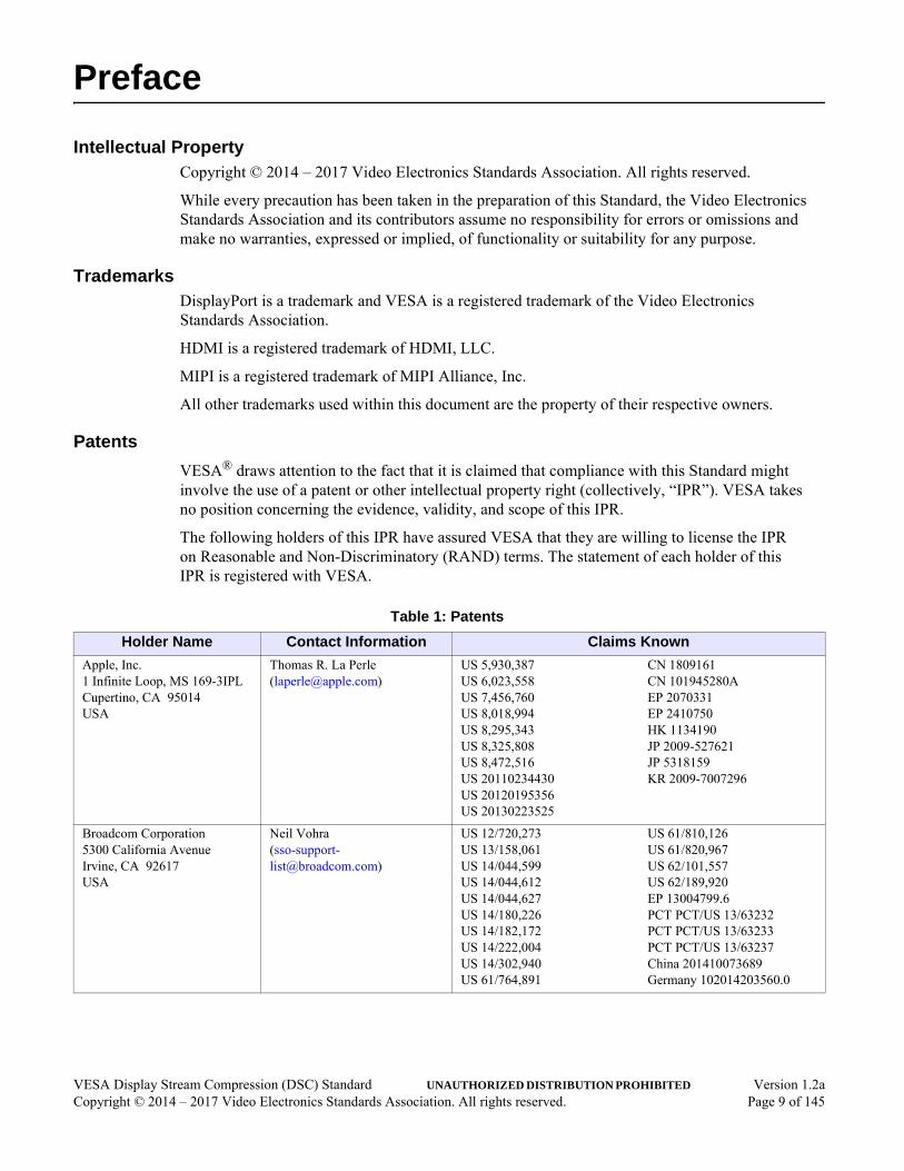
VESA® draws attention to the fact that it is claimed that compliance with this Standard might involve the use of a patent or other intellectual property right (collectively, “IPR”). VESA takes no position concerning the evidence, validity, and scope of this IPR.
The following holders of this IPR have assured VESA that they are willing to license the IPR on Reasonable and Non-Discriminatory (RAND) terms. The statement of each holder of this IPR is registered with VESA.
Table 1: Patents
Holder Name Contact Information Claims Known
Apple, Inc.1 Infinite Loop, MS 169-3IPLCupertino, CA 95014USA
Thomas R. La Perle([email protected])
US 5,930,387US 6,023,558US 7,456,760US 8,018,994US 8,295,343US 8,325,808US 8,472,516US 20110234430US 20120195356US 20130223525
CN 1809161CN 101945280AEP 2070331EP 2410750HK 1134190JP 2009-527621JP 5318159KR 2009-7007296
Broadcom Corporation5300 California AvenueIrvine, CA 92617USA
Neil Vohra([email protected])
US 12/720,273US 13/158,061US 14/044,599US 14/044,612US 14/044,627US 14/180,226US 14/182,172US 14/222,004US 14/302,940US 61/764,891
US 61/810,126US 61/820,967US 62/101,557US 62/189,920EP 13004799.6PCT PCT/US 13/63232PCT PCT/US 13/63233PCT PCT/US 13/63237China 201410073689Germany 102014203560.0
VESA Display Stream Compression (DSC) Standard UNAUTHORIZED DISTRIBUTION PROHIBITED Version 1.2aCopyright © 2014 – 2017 Video Electronics Standards Association. All rights reserved. Page 9 of 145

Attention is drawn to the possibility that some of the elements of this VESA Standard might be the subject of IPR other than those identified above. VESA shall not be held responsible for identifying any or all such IPR, and has made no inquiry into the possible existence of any such IPR.
THIS STANDARD IS BEING OFFERED WITHOUT ANY WARRANTY WHATSOEVER, AND IN PARTICULAR, ANY WARRANTY OF NON-INFRINGEMENT IS EXPRESSLY DISCLAIMED. ANY IMPLEMENTATION OF THIS STANDARD SHALL BE MADE ENTIRELY AT THE IMPLEMENTER’S OWN RISK, AND NEITHER VESA, NOR ANY OF ITS MEMBERS OR SUBMITTERS, SHALL HAVE ANY LIABILITY WHATSOEVER TO ANY IMPLEMENTER OR THIRD PARTY FOR ANY DAMAGES OF ANY NATURE WHATSOEVER DIRECTLY OR INDIRECTLY ARISING FROM THE IMPLEMENTATION OF THIS STANDARD.
MediaTek, Inc.
No. 1, Dusing 1st RoadHsinchu Science ParkHsinchu City 30078Taiwan
Chu-Cheng Ju([email protected])
US 13/913,520US 13/936,231US 13/937,224US 14/048,06061/712,94961/712,97561/865,345
61/895,45461/895,46161/902,86761/904,49061/922,13561/920,841
International application numbers:PCT/CN2013/083061PCT/CN2013/083118PCT/CN2013/083739
Microsoft Corporation1 Microsoft WayRedmond, WA 98052USA
Peggy Maloney([email protected])
US 7,155,055
QUALCOMM, Inc.5775 Morehouse DriveSan Diego, CA 92121USA
Thomas R. Rouse([email protected])
US 8,238,428US 20120300835US 20120328004CN 101682783EP 2149263IN 1783/MUMNP/2009
IN 9586/CHENP/2013JP 2010-525676KR 1096467TWI380697WO 2012178053
Samsung Electronics Co., Ltd.601 McCarthy BoulevardMilpitas, CA 95035USA
Dong Chan Park([email protected])
US 7,860,322US 7,860,323US 8,126,053
US 8,165,195US 8,311,110
Table 1: Patents (Continued)
Holder Name Contact Information Claims Known
VESA Display Stream Compression (DSC) Standard UNAUTHORIZED DISTRIBUTION PROHIBITED Version 1.2aCopyright © 2014 – 2017 Video Electronics Standards Association. All rights reserved. Page 10 of 145

Support for this StandardTo obtain the latest Standard and any support documentation, contact VESA.
If you have a product that incorporates Display Stream Compression (DSC), ask the company that manufactured your product for assistance. If you are a manufacturer, VESA can assist you with any clarification you might require. Submit all comments to [email protected].
AcknowledgmentsThis document would not have been possible without the efforts of VESA’s Display Stream Compression Task Group. In particular, Table 2 lists the individuals and their companies that contributed significant time and knowledge to this version of the Standard.
Table 2: Main Contributors to DSC v1.2a
Company Name Contribution
Advanced Micro Devices, Inc. Dennis Au Contributor
Nick Chorney Contributor, Reviewer
Graeme Cox Contributor
Jim Hunkins Task Group Vice-Chair, Contributor, Reviewer
Brent Jackson Contributor
Minghua Zhu Contributor, Reviewer
Apple, Inc. Bob Ridenour Contributor
Broadcom Corporation Rick Berard Contributor, Reviewer
Sandy (Alexander) MacInnis Primary Technical Contributor
Fred Walls Document Editor, Primary Technical Contributor
DisplayLink (UK), Ltd. Dan Ellis Contributor
Eric Hamaker Contributor
Extron Electronics Mike Izquierdo Contributor
Alex Petrulian Contributor, Reviewer
Hardent, Inc. Simon Bussieres Contributor, Reviewer
Avrum Warshawky Contributor
Intel Corporation Nausheen Ansari Contributor
Simon Ellis Contributor
George Hayek Contributor
intoPIX SA Jean-Baptiste Lorent Contributor
Gael Rouvroy Contributor
Jupiter Systems Emme Yarwood Contributor
Lattice Semiconductor (formerly Silicon Image, Inc.)
Donny (Young-Don) Bae Contributor
Larry Thompson Contributor
LG Electronics Michael Frank Contributor
Marseille Networks, Inc. Remi Lenoir Contributor
Mediatek, Inc. Tung-Hsing Wu Contributor
VESA Display Stream Compression (DSC) Standard UNAUTHORIZED DISTRIBUTION PROHIBITED Version 1.2aCopyright © 2014 – 2017 Video Electronics Standards Association. All rights reserved. Page 11 of 145

MegaChips Technology America
Alan Kobayashi Contributor
NVIDIA Corporation David Stears Contributor, Reviewer
Parade Technologies, Ltd. Craig Wiley Contributor
Qualcomm, Inc. Harris Chan Contributor
Ramprasad Chandrasekaran Contributor
James Goel Contributor, Reviewer
Natan Jacobson Contributor
Rajan Joshi Contributor
Mohsin Riaz Contributor
Vijayaraghavan Thirumalai Contributor
Samsung Display Company Greg Cook Contributor
Dale Stolitzka Task Group Chair, Contributor, Reviewer
Samsung Electronics Co., Ltd. Deoksoo Park Reviewer
Taewoo Kim Reviewer
Synaptics, Inc. Bruce Chin Contributor, Reviewer
Jeff Lukanc Contributor
Toshiba America Information Systems, Inc.
Tomoo Yamakage Contributor
Table 2: Main Contributors to DSC v1.2a (Continued)
Company Name Contribution
VESA Display Stream Compression (DSC) Standard UNAUTHORIZED DISTRIBUTION PROHIBITED Version 1.2aCopyright © 2014 – 2017 Video Electronics Standards Association. All rights reserved. Page 12 of 145

Revision History
Table 3: Revision History
Date Version Description
January 18, 2017 1.2a Added proposed changes from the following DSC v1.2 SCRs:
• Applied SCR# DSC 1.2 RGB 16bpc clarification
• Section 6.1 and Section 7.7 – Corrections to Co and Cg when bits_per_component is equal to 16
• Applied SCR# DSC 1.2 QP Restriction in 1.1 YCbCr Mode
• Table 4-3 – Updated range_max_qp description
• Added qp-related text to Table E-4/Table E-5 introduction
• Applied SCR# DSC 1.2 4:2:2 mode specification typos
• Section 3.10.1 – Corrected last paragraph
• Section 6.5.3.1 – Corrected weightedSad equation (changed + to *)
• Applied SCR# Change on rules for slice_height/picture_height in 4:2:2 and 4:2:0
• Table 4-1 – Revised last two paragraphs of slice_height and slice_width definitions
• Applied SCR# DSC 1.2 4:2:0 prediction and RC bug fixes SCR v4
• Section 1.3, Section 3.4, Section 6.4.1, Section 6.5.1, Section 6.8.4 – Added Native 4:2:0 mode-related clarifications
• Table 1-1 – Added DSC v1.2a-supported modes, removed DSC v1.2 support for Native 4:2:0 mode
• Applied SCR# DSC 1.2 alternative encoder ICH selection SCR v5
• Section 6.5.3.3 – Added
• Applied SCR# DSC 1.2 YCbCr QP map spec typo fix SCR
• Section 6.8.6 – Revised second paragraph
• Applied SCR# DSC 1.2 C model max QP check SCR v2
• Adds new paragraph to Table E-4/Table E-5 introduction
January 20, 2016 1.2 • Applied major update to support Native 4:2:2 and 4:2:0 modes, and 14 and 16bpc
• Changed pixelsPerGroup to pixelsInGroup in select locations within Section 6.8.1
• Updated Table 2 and Table H-1 contributor lists
• Applied new template style to cover and Support for this Standard section
• Global changes
• Corrected PPS to match C model
• Adjusted ICH lambda based on flatness of next group
• Applied rate control changes to improve performance on white noise pictures
• Applied TGR and GMR feedback, including minor editorial changes
• Applied minor text corrections and clarifications throughout document
VESA Display Stream Compression (DSC) Standard UNAUTHORIZED DISTRIBUTION PROHIBITED Version 1.2aCopyright © 2014 – 2017 Video Electronics Standards Association. All rights reserved. Page 13 of 145

August 1, 2014 1.1 • Table 1-3 – Updated DSC Model C document information.
• Table 4-1, dsc_version_minor – PPS version updated to DSC v1.1.
• Changed overflow avoid condition, and action is now to set QP to the maximum QP of range 14. No flatness adjustment is made if current QP is equal to the maximum QP of range 14. Second flatness check is bypassed for 1-pixel groups. Updated Figure 6-12.
• Applied SCR# DSC 1.0 Update scale_increment_interval. Updated scale_increment_interval value in Table E-2 and added new Table E-3. Subsequent tables renumbered accordingly and cross-references updated.
March 10, 2014 1.0 Initial release of the Standard.
Table 3: Revision History (Continued)
Date Version Description
VESA Display Stream Compression (DSC) Standard UNAUTHORIZED DISTRIBUTION PROHIBITED Version 1.2aCopyright © 2014 – 2017 Video Electronics Standards Association. All rights reserved. Page 14 of 145

1 Introduction
This VESA® document specifies the bitstream syntax and semantic, encoding process and decoding process of the Display Stream Compression (DSC) Standard.
1.1 Document OrganizationThis Standard is organized into the following sections and annexes:
• Section 1 – Introduction
This section defines the high-level industry needs for DSC and the resulting technical objectives that the remaining sections of this Standard are intended to satisfy. This section also includes a glossary of terms for the overall Standard, references, and overview of DSC.
• Section 2 – Requirements (Informative)
This section lists the requirements that form the basis of this Standard.
• Section 3 – Theory of Operation (Informative)
This section provides a general overview of the DSC algorithm. It includes background information, high-level description, and broad explanation for the algorithm.
• Section 4 – Syntax (Normative)
This section specifies the syntax for DSC bitstreams.
• Section 5 – Capability Parameter Set (Informative)
This section lists and describes the recommended Capability Parameter Set.
• Section 6 – Encoding Process (Normative)
This section describes the processing required for DSC-compatible encoders.
• Section 7 – Decoding Process (Normative)
This section describes the processing required for DSC-compatible decoders.
• Annex A – DSC File Format (Normative)
This annex defines the .DSC file format.
• Annex B – Simple 4:2:2 Mode (Informative)
This annex describes an easy method that can be referenced by an application specification to convert 4:2:2 to 4:4:4, and vice versa, because DSC operates on 4:4:4 video.
• Annex C – Guidance for Mapping to Transport (Informative)
This annex provides guidance to application specification committees to assist in using DSC within such specifications.
• Annex D – Guidance for Hardware Implementations (Informative)
This annex provides guidance for hardware implementations of the DSC algorithm.
• Annex E – Derivation of Rate Control Parameters (Informative)
This annex provides explanation and guidance regarding how to derive PPS parameters related to rate control.
VESA Display Stream Compression (DSC) Standard UNAUTHORIZED DISTRIBUTION PROHIBITED Version 1.2aCopyright © 2014 – 2017 Video Electronics Standards Association. All rights reserved. Page 15 of 145
• Annex F – Hypothetical Reference Decoder (Informative)
This annex presents a hypothetical reference decoder model that could be used to verify stream compliance. Although some details in this annex are specific to the 4:4:4 modes, the same concepts also apply to Native and Simple 4:2:2 mode and Native 4:2:0 mode.
• Annex G – Slice Timing Examples (Informative)
This annex describes and analyzes slice timing use cases.
• Annex H – Main Contributor History (Previous Versions)
This annex lists the contributors of past releases of this Standard.
1.2 Display Stream Compression ObjectivesThe DSC algorithm is designed to enable low-cost hardware implementations of visually lossless video compression over display links.
1.3 Display Stream Compression VersionsDSC v1.2 contained some issues related to the Native 4:2:0 mode definition, and therefore Native 4:2:0 mode was deprecated in an errata. The primary purpose of DSC v1.2a is to correct these issues so that Native 4:2:0 mode may be fully supported. All other modes in DSC v1.2 are fully compatible with DSC v1.2a.
Although DSC v1.2 replaces DSC v1.1, DSC v1.1 implementations are still fully supported in this Standard. The main objectives of DSC v1.2 are to add support for 14 and 16 bits per component (bpc) and Native 4:2:0 and 4:2:2 modes. DSC v1.2 also includes minor adjustments to some parts of the algorithm.
DSC streams may be configured to conform to DSC v1.1. In this case, a DSC v1.2 encoder would then generate an identical stream to a DSC v1.1 encoder, and such encoded streams could be decoded by either a DSC v1.1 or DSC v1.2 decoder.
Transports that support carriage of DSC v1.1 bitstreams that also allow for carriage of DSC v1.2 and higher bitstreams shall require that all encoders must be capable of generating a DSC v1.1 stream. Additionally, all decoders must be capable of decoding a DSC v1.1 stream. This restriction does not apply to transports that do not support DSC v1.1.
A picture is encoded using the version of DSC that is specified by the PPS dsc_version_minor field value, as follows:
• 0x1: Corresponding bitstream is a DSC v1.1 bitstream
• 0x2: Corresponding bitstream is a DSC v1.2 or DSC v1.2a bitstream
Note: DSC v1.0 is deprecated and no longer supported.
VESA Display Stream Compression (DSC) Standard UNAUTHORIZED DISTRIBUTION PROHIBITED Version 1.2aCopyright © 2014 – 2017 Video Electronics Standards Association. All rights reserved. Page 16 of 145

1.4 Acronyms, Initialisms, and Abbreviations
Table 1-1: DSC Supported Modes, by Version
Mode DSC v1.1 DSC v1.2 DSC v1.2a4:4:4 RGB, 8, 10, and 12bpc ✔ ✔ ✔
4:4:4 YCbCr, 8, 10, and 12bpc ✔ ✔ ✔
4:2:2 YCbCr 8, 10, and 12bpc ✔
(Simple mode only)✔
(Native and Simple modes)✔
(Native and Simple modes)
4:2:0 YCbCr, 8, 10, and 12bpc ✔
Any mode, 14 and 16bpc ✔ ✔
Table 1-2: Acronyms, Initialisms, and Abbreviations
Acronym/Abbreviation Stands for
BP Block Prediction
bpc bits per component
bpg bits per group
bpp bits per pixel
CBR Constant Bit Rate
CRC Cyclic Redundancy Check
CSC Color Space Conversion
DSC Display Stream Compression (VESA)
DSU-VLC Delta Size Unit-Variable Length Coding
ECC Error Correcting Code
eDP Embedded DisplayPort (VESA)
FIFO First-In, First-Out
HBlank Horizontal blanking period
HRD Hypothetical reference decoder
ICH Indexed Color History
ICH-mode Indexed Color History mode of coding
lsb least significant bit
LRU Least-Recently Used
MAP Median Adaptive Prediction
MMAP Modified Median-Adaptive Prediction
MPP Midpoint Prediction
MRU Most-Recently Used
P-mode Predictive mode of coding
PPS Picture Parameter Set
VESA Display Stream Compression (DSC) Standard UNAUTHORIZED DISTRIBUTION PROHIBITED Version 1.2aCopyright © 2014 – 2017 Video Electronics Standards Association. All rights reserved. Page 17 of 145

qLevel Quantization level. Exponent applied to 2 to produce a quantization divisor. There are separate qLevelY (luma) and qLevelC (qLevelCo and qLevelCg; chroma) values.
QP Quantization Parameter
RC Rate Control
SAD Sum of Absolute Differences
SSM Substream Multiplexing
SSP Substream Processor
VBR Variable Bit Rate
VESA Video Electronics Standards Association
VLC Variable length code
Table 1-2: Acronyms, Initialisms, and Abbreviations (Continued)
Acronym/Abbreviation Stands for
VESA Display Stream Compression (DSC) Standard UNAUTHORIZED DISTRIBUTION PROHIBITED Version 1.2aCopyright © 2014 – 2017 Video Electronics Standards Association. All rights reserved. Page 18 of 145

1.5 Glossary
Table 1-3: Glossary of Terms
Term Definition
4:2:0 Format for YCbCr video in which the chrominance components are horizontally and vertically subsampled by 2 and 2, respectively.
4:2:2 Format for YCbCr video in which both chrominance components are horizontally subsampled by 2.
4:4:4 Format for RGB or YCbCr video in which the chrominance components are not subsampled.
4:4:4:4 Container format used in Native 4:2:2 mode. Consists of four components in which the chrominance components are not subsampled.
Bit depth Number of bits allocated for a given component in the coded color space. This value is one larger for Co and Cg components than Y components.
Bits per component bpc. Number of bits for each of R, G, and B, or Y, Cb, and Cr in the source format of the encoder, or destination format of the decoder.
Bits per pixel bpp. Number of bits sent from an encoder and received by a decoder, per unit of pixel time. The bits per pixel rate can have a non-integer value, in which case the number of bits received averaged over a number of successive pixels is an integer.
Bitstream Stream of bits conforming to this Standard. Represents the effects of the multiplexing functions specified by this Standard, as well as the various layers. See Layer.
Block prediction Prediction method in which a sample is predicted by using a sample of the same component type from a previously reconstructed pixel that is to the left of the predicted pixel.
Block prediction vector Vector that indicates the relative pixel location that is being used for block prediction.
Chunk Portion of the bitstream that comprises a set of data bytes. For each slice, there are the same number of chunks as lines within a slice. Chunk sizes vary and can be zero-length in variable bit rate (VBR) mode. Every chunk is the same size in constant bit rate (CBR) mode.
Constant bit rate mode CBR. Rate control scheme which ensures that the compressed bit rate measured over a slice is equal to a specified value.
Container A virtual 4:4:4 or 4:4:4:4 half-width picture created by repackaging samples from a 4:2:0 or 4:2:2 picture, respectively. Containers are coded like pictures and allow native coding of 4:2:0 and 4:2:2 formats.
Container pixel time In Native 4:2:2 and 4:2:0 modes, amount of time that it takes for a single container pixel (or equivalently a pair of actual pixels) to be consumed or generated.
Current samples In general, the samples belonging to the current group being coded. In the context of block prediction search, the set of current samples refers to the samples corresponding to the 9x1 set of pixels that is used in all the SADs for determining the block prediction vector for the current group.
Display interface Wired or wireless link conveying a DSC stream, from a DSC Source device to a separate DSC Sink device.
DSC Sink device System or subsystem comprising a DSC decoder and a display, wherein a DSC stream is received by way of a display interface, and the received DSC stream is decoded and the result is shown on the display.
DSC Source device System or subsystem comprising a DSC encoder, wherein an uncompressed stream of video information intended for display is compressed by the encoder, and the resulting DSC stream is communicated to a DSC Sink device by way of a display interface.
Entropy decoder Part of the DSC algorithm that parses syntax elements for a single component’s substream.
VESA Display Stream Compression (DSC) Standard UNAUTHORIZED DISTRIBUTION PROHIBITED Version 1.2aCopyright © 2014 – 2017 Video Electronics Standards Association. All rights reserved. Page 19 of 145

Entropy encoder Part of the DSC algorithm that generates the Substream Layer data for each component.
Fractional bits Number of bits that are to the right of the binary point. For example, the binary number 101.01 has two fractional bits and represents the decimal value 5.25.
Funnel shifter Logical function that allows many types of shifts; in this Standard, a funnel shifter shifts an n-bit word a programmable number of positions, while optionally inserting a mux word at a programmable position.
Group Set of three consecutive pixels, in raster scan order, within one slice that is coded together and is the basis for many of the functions in DSC.
HRD delay End-to-end rate buffer delay of an idealized DSC system. The value is in units of pixel time and is equal to the buffer model size divided by the nominal bit rate.
Hypothetical reference decoder
HRD. Theoretical video buffer model that ensures an encoded stream can be correctly buffered and played back with a decoder.
Indexed color history ICH. Part of the DSC algorithm that allows efficient coding of recently coded pixel values.
Inverse quantization Function that maps quantized values to a set of discrete original values. In this Standard, inverse quantization is done using a logical left shift.
Layer Portion of the hierarchy used in this Standard. A DSC bitstream can differ from a combination of bits from different layers due to the actions of the multiplexing functions specified within this Standard. See Bitstream.
Line buffer or line storage
Memory used to retain reconstructed pixel values from the previous line.
Median adaptive prediction
Prediction method in which a sample is predicted by using the median of several predictors.
Midpoint prediction Prediction method in which a sample is predicted by using the midpoint (or approximate midpoint) of the component’s range.
Mux word Fixed number of bits from a single Substream Layer bitstream. See Chunk.
Picture Single frame (or interlaced field) of pixels.
Picture Layer Set of bits (including an optional Picture Parameter Set) that represent a single picture.
Picture Parameter Set PPS. Set of parameters that is optionally transmitted at the start of a coded picture, which provides information necessary to decode the picture.
Pixel time Amount of time that it takes for a single pixel to be consumed or generated.
Prediction Process that produces an estimated value for a sample, based on previously coded values. Prediction decorrelates the pixel sample data and generally reduces the amount of information that needs to be coded.
Quantization Function that maps a large set of input values to a smaller set of output values. In this Standard, quantization is done by rounding and shifting input values.
Reconstructed pixels Pixels that the decoder uses as output pixels. The encoding process uses these values for prediction.
Reconstruction Process that the decoder uses to determine the output pixels, and that the encoder uses to determine reconstructed pixel values.
Reference samples In the block prediction search, the set of reference samples refers to the samples corresponding to the 9x1 set of pixels located some number of pixels to the left of the current samples.
Residual Difference between a predicted sample and the actual sample.
Table 1-3: Glossary of Terms (Continued)
Term Definition
VESA Display Stream Compression (DSC) Standard UNAUTHORIZED DISTRIBUTION PROHIBITED Version 1.2aCopyright © 2014 – 2017 Video Electronics Standards Association. All rights reserved. Page 20 of 145
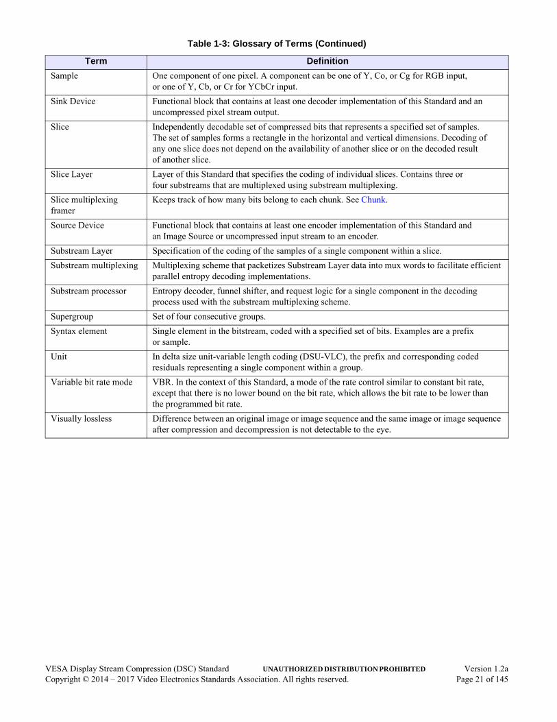
Sample One component of one pixel. A component can be one of Y, Co, or Cg for RGB input, or one of Y, Cb, or Cr for YCbCr input.
Sink Device Functional block that contains at least one decoder implementation of this Standard and an uncompressed pixel stream output.
Slice Independently decodable set of compressed bits that represents a specified set of samples. The set of samples forms a rectangle in the horizontal and vertical dimensions. Decoding of any one slice does not depend on the availability of another slice or on the decoded result of another slice.
Slice Layer Layer of this Standard that specifies the coding of individual slices. Contains three or four substreams that are multiplexed using substream multiplexing.
Slice multiplexing framer
Keeps track of how many bits belong to each chunk. See Chunk.
Source Device Functional block that contains at least one encoder implementation of this Standard and an Image Source or uncompressed input stream to an encoder.
Substream Layer Specification of the coding of the samples of a single component within a slice.
Substream multiplexing Multiplexing scheme that packetizes Substream Layer data into mux words to facilitate efficient parallel entropy decoding implementations.
Substream processor Entropy decoder, funnel shifter, and request logic for a single component in the decoding process used with the substream multiplexing scheme.
Supergroup Set of four consecutive groups.
Syntax element Single element in the bitstream, coded with a specified set of bits. Examples are a prefix or sample.
Unit In delta size unit-variable length coding (DSU-VLC), the prefix and corresponding coded residuals representing a single component within a group.
Variable bit rate mode VBR. In the context of this Standard, a mode of the rate control similar to constant bit rate, except that there is no lower bound on the bit rate, which allows the bit rate to be lower than the programmed bit rate.
Visually lossless Difference between an original image or image sequence and the same image or image sequence after compression and decompression is not detectable to the eye.
Table 1-3: Glossary of Terms (Continued)
Term Definition
VESA Display Stream Compression (DSC) Standard UNAUTHORIZED DISTRIBUTION PROHIBITED Version 1.2aCopyright © 2014 – 2017 Video Electronics Standards Association. All rights reserved. Page 21 of 145

1.6 Symbols
1.6.1 Bit OrderingThe order of bits within the DSC bitstream is specified in the syntax portion of this Standard. With each multi-bit code, the leftmost bit is communicated first, and the rightmost bit is communicated last. Codes are segmented into multiple portions that are transmitted discontinuously, due to the multiplexing functions specified within this Standard.
1.6.2 FunctionsThe bitstream syntax is specified in C-like language. Operators used in this Standard, such as +, -, *, /, <<, >>, and others are interpreted the same way as C operators. Standard C library functions, such as ceil() and floor(), have the same meaning as in C. Some C macros are also referenced within this Standard:
#define CLAMP(X, MIN, MAX) ((X)>(MAX) ? (MAX) : ((X)<(MIN) ? (MIN) : (X)))
#define MAX(X, Y) ((X) > (Y) ? (X) : (Y))
#define MIN(X, Y) ((X) < (Y) ? (X) : (Y))
#define ABS(X) ((X) < 0 ? (-1 * (X)) : (X))
A fixed-point equivalent of ceil(log2 (X + 1)), where log2() is the base-2 logarithm function, is defined as follows:
int ceil_log2(int val)
{
int ret = 0, x;
x = val;
while(x) { ret++; x >>= 1; }
return(ret);
}
VESA Display Stream Compression (DSC) Standard UNAUTHORIZED DISTRIBUTION PROHIBITED Version 1.2aCopyright © 2014 – 2017 Video Electronics Standards Association. All rights reserved. Page 22 of 145

1.7 Conventions• Internal signals/states – Bold, lowercase first letter followed by CamelCase in fixed-width
typeface. For example, rcModelFullness or rcXformOffset. Use of bold blue text indicates that the term is hyperlinked to its definition within this Standard.
• Parameters in PPS or bitstream syntax elements – Bold, italic, lowercase words and/or abbreviations separated by underscores. For example, bits_per_pixel or initial_dec_delay. Use of bold italic blue text indicates that the term is hyperlinked to its definition within this Standard.
• Function names in the C model – Uppercase first letter followed by CamelCase in fixed-width typeface. For example, MaxOverPixelsInGroup or QuantDivisor.
1.8 Reference Documents
Table 1-4: Normative Reference Document
Document Version/Revision
Referenced As
Publication Date
VESA DSC C Model – see www.vesa.org Version 1.57 – December 12, 2016
Table 1-5: Informative Reference Documents
Document Version/Revision
Publication Date
Malvar, H. S., G. J. Sullivan, and S. Srinivasan, Lifting-based reversible color transformations for image compression, Proceedings of SPIE, Vol. 7073.
– 2008
Martucci, S. A., Reversible compression of HDTV images using median adaptive prediction and arithmetic coding, IEEE International Symposium on Circuits and Systems, Vol. 2.
– 1990
VESA Display Stream Compression Conformance Test Guideline (DSC CTG) Version 1.0 April 27, 2015
VESA Display Stream Compression (DSC) Standard UNAUTHORIZED DISTRIBUTION PROHIBITED Version 1.2aCopyright © 2014 – 2017 Video Electronics Standards Association. All rights reserved. Page 23 of 145

VESA Display Stream Compression (DSC) Standard UNAUTHORIZED DISTRIBUTION PROHIBITED Version 1.2aCopyright © 2014 – 2017 Video Electronics Standards Association. All rights reserved. Page 24 of 145
2 Requirements (Informative)The requirements that form the basis of this Standard include:
• Support TVs, monitors, and mobile panels, with either higher resolution than could otherwise be supported with a given display link, or with fewer lanes or lower rate in the display link
• RGB and YCbCr input format, supporting 4:4:4, 4:2:2, and 4:2:0 sampling
• Input bits per component (bpc) of 8, 10, 12, 14, and 16
• Programmable compressed bit rate of 8bpp and higher (6bpp and higher for 4:2:0 pictures)
• Visually lossless quality at the specified target bit rate, using a wide variety of both still images and motion video sequences
• Real-time encoding and decoding
• Low cost
• Support of slices to enable partial update of compressed frame buffers, and for bounding the range of artifacts resulting from errors in the received bitstream
This Standard is designed for use over any display link. Examples include, but are not limited to,
MIPI® Alliance’s Display Serial Interface (DSI) Specification, DisplayPort™ (DP), Embedded
DisplayPort (eDP), and High-Definition Multimedia Interface (HDMI®).

3 Theory of Operation (Informative)
3.1 OverviewThis section provides a general overview of the DSC algorithm. It includes background information, high-level description, and broad explanation for the algorithm.
This Standard specifies the encoding process, bitstream syntax and semantics, and decoding process used for compressing display streams. The entire system is designed to work in real-time. Uncompressed video enters the encoder in real-time, in raster scan order. The encoder compresses incoming pixels to form a bitstream, then temporarily stores portions of the bitstream in its rate buffer. The rate buffer’s output is the Picture Layer of a DSC bitstream (i.e., everything except the picture parameter set (PPS)). The DSC bitstream is conveyed in real-time from the encoder to the decoder, by way of a Transport Layer, which is outside the scope of this Standard. The decoder receives the bitstream into its rate buffer, which temporarily stores portions of the bitstream. The decoder decodes bits from the rate buffer and then forms uncompressed pixels, which are output in real-time and raster scan order, and then sent to a display. The image output from the decoding process has the same format as the image input to the encoding process. Figure 3-1 illustrates how DSC works in an end-to-end system.
Figure 3-1: DSC Use in End-to-end System
Display Link
DSC Bitstream
Image Source
DSC Encoder
Internal Connection
Source Device
DSC Decoder
Display
Internal Connection
Sink Device
VESA Display Stream Compression (DSC) Standard UNAUTHORIZED DISTRIBUTION PROHIBITED Version 1.2aCopyright © 2014 – 2017 Video Electronics Standards Association. All rights reserved. Page 25 of 145

The DSC bitstream consists of one or more pictures coded using the Picture Layer syntax, which includes a Slice Layer syntax. Correct decoding also requires that an identical PPS be used at the encoder and decoder. The bitstream reflects the substream multiplexing (SSM) process and slice multiplexing process operations. The PPS contains parameters that the decoder needs to correctly decode pictures. Figure 3-2 illustrates the DSC syntax and application layer hierarchy.
Figure 3-2: DSC Syntax and Application Layer Hierarchy
Substream Y
Substream Co
Substream Cg
Substream Multiplexing
Substream Y
Substream Co
Substream Cg
Substream Multiplexing
Slice Multiplexing
PPS
…
Bitstream
Substream Layer Slice Layer Picture Layer
VESA Display Stream Compression (DSC) Standard UNAUTHORIZED DISTRIBUTION PROHIBITED Version 1.2aCopyright © 2014 – 2017 Video Electronics Standards Association. All rights reserved. Page 26 of 145

The Picture Layer operates in units of entire pictures. A picture is either a frame (when coding progressive format video) or a field (when coding interlaced format video). Each picture consists of an integer number n of contiguous, non-overlapping, rectangular slices. Slices within a picture have identical dimensions. Slice coding is specified by the Slice Layer. Each slice is independently decoded, without reference to other slices. There can be one or multiple slices per line. In the case of multiple slices per line, bits from the slices covering one line are multiplexed in the bitstream by a slice multiplexing process specified in Section 3.9. Each slice consists of a set of groups, and each group is a set of three or six consecutive pixels in raster scan order. Each group is coded with three or four delta size unit-variable length coding (DSU-VLC) units, each of which is a specific type of variable length code (VLC). Some groups have one or more bits that signal specific decoding operations. The bits that comprise each component form a substream. There are three or four substreams, depending on the input chroma subsampling, where each substream maps to one of the encoded units for a group. The substreams are multiplexed according to the Substream Multiplexing (SSM) process, which is described in Section 3.5.2. The bits that form a coded slice result from the SSM process. Figure 3-3 illustrates the relationship of pictures and slices with the PPS.
Figure 3-3: Relationship between Picture Parameter Set, Pictures, and Slices
Slice Slice
Slice Slice
Slice
SliceSlice
Slice
PPS
Picture
VESA Display Stream Compression (DSC) Standard UNAUTHORIZED DISTRIBUTION PROHIBITED Version 1.2aCopyright © 2014 – 2017 Video Electronics Standards Association. All rights reserved. Page 27 of 145

Figure 3-4 illustrates the DSC encoding process, which generates bitstreams that precisely conform to the independently specified bit rate. The bit rate is specified in units of bits per pixel time, and as such, the rate is specified algorithmically because units of pixel time are the same at the encoder’s input and output. The number of bits used to code each pixel group can vary considerably. The rate buffer converts the variable number of bits used to code each group into a constant bit rate. The encoding process includes a rate control (RC) to manage rate buffer fullness.
Figure 3-4: Encoding Process
The DSC encoding process uses these subprocesses:
• Color space conversion (in case of RGB input) to reversible YCoCg (YCoCg-R), which is bypassed for YCbCr input
• Three sample value and generation of residual value prediction methods:
• Modified Median-Adaptive Prediction (MMAP)
• Block Prediction (BP)
• Midpoint Prediction (MPP)
• Quantization of residual values and reconstruction of sample values
• Indexed color history (ICH)
• Entropy coding using delta size unit-variable length coding (DSU-VLC)
• Rate control (RC)
VLC Entropy Coding
Rate Control
ICH
Reconstructed Pixel Values
Line Buffer
# of Bits
Flatness Determination
Flatness Indication Flatness Indication
Predictors, Quantization, and Reconstruction
Image Input
BufferRGB to
YCoCg-R (if RGB in)
Bitstream OutputSubstream
Multiplexing Rate Buffer
QP
VESA Display Stream Compression (DSC) Standard UNAUTHORIZED DISTRIBUTION PROHIBITED Version 1.2aCopyright © 2014 – 2017 Video Electronics Standards Association. All rights reserved. Page 28 of 145
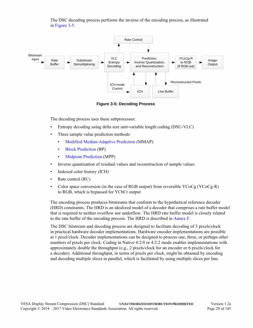
The DSC decoding process performs the inverse of the encoding process, as illustrated in Figure 3-5.
Figure 3-5: Decoding Process
The decoding process uses these subprocesses:
• Entropy decoding using delta size unit-variable length coding (DSU-VLC)
• Three sample value prediction methods:
• Modified Median-Adaptive Prediction (MMAP)
• Block Prediction (BP)
• Midpoint Prediction (MPP)
• Inverse quantization of residual values and reconstruction of sample values
• Indexed color history (ICH)
• Rate control (RC)
• Color space conversion (in the case of RGB output) from reversible YCoCg (YCoCg-R) to RGB, which is bypassed for YCbCr output
The encoding process produces bitstreams that conform to the hypothetical reference decoder (HRD) constraints. The HRD is an idealized model of a decoder that comprises a rate buffer model that is required to neither overflow nor underflow. The HRD rate buffer model is closely related to the rate buffer of the encoding process. The HRD is described in Annex F.
The DSC bitstream and decoding process are designed to facilitate decoding of 3 pixels/clock in practical hardware decoder implementations. Hardware encoder implementations are possible at 1 pixel/clock. Decoder implementations can be designed to process one, three, or perhaps other numbers of pixels per clock. Coding in Native 4:2:0 or 4:2:2 mode enables implementations with approximately double the throughput (e.g., 2 pixels/clock for an encoder or 6 pixels/clock for a decoder). Additional throughput, in terms of pixels per clock, might be obtained by encoding and decoding multiple slices in parallel, which is facilitated by using multiple slices per line.
Rate Control
RateBuffer
ICH-mode Control
Reconstructed Pixels
Prediction, Inverse Quantization, and Reconstruction
YCoCg-Rto RGB
(if RGB out)
Bitstream Input VLC
Entropy Decoding
Line BufferICH
Substream Demultiplexing
Image Output
VESA Display Stream Compression (DSC) Standard UNAUTHORIZED DISTRIBUTION PROHIBITED Version 1.2aCopyright © 2014 – 2017 Video Electronics Standards Association. All rights reserved. Page 29 of 145

3.2 Color Space ConversionRGB video input to the encoding process is converted to YCoCg before any other processing is performed [Malvar 2008]. The reversible form of YCoCg is used (YCoCg-R), and as such, the number of bits per each of the two chroma components is one greater in YCoCg-R than the number of bits in RGB. In the case of 16 bpc input, the least-significant bit of each YCoCg chroma component is rounded off to limit the syntax element sizes and data path widths. This means that the transformation is no longer reversible and there is no mathematically lossless encoding for 16 bpc; however, in most applications, these rounded least-significant bits have a negligible effect on the perceived pictures. In the case of YCbCr input, no color space conversion (CSC) is performed.
The inverse color space conversion is performed at the end of the decoding process.
3.3 Prediction and QuantizationEach group of pixels is coded using either predictive coding (P-mode) or indexed color history coding (ICH-mode). P-mode is described in this section.
For P-mode, there are three prediction methods:
• Modified Median-Adaptive Prediction (MMAP)
• Block Prediction (BP)
• Midpoint Prediction (MPP)
The encoder and decoder automatically select MMAP, BP, or MPP, using the same algorithm in each, without signaling the selection in the bitstream. Encoders are required to support all three prediction methods; however, BP is optional for decoders, and implementers can choose whether to support BP, based on cost and quality considerations.
In an encoder, each sample is predicted using the selected predictor. The predicted value is subtracted from the original pixel value, and the resulting difference is quantized. Each quantized residual, also referred to as an “error,” is then entropy-coded if P-mode is selected. The encoder also performs a reconstruction step wherein the inverse-quantized error is added to the prediction so that the encoder and decoder have and use the same reference pixels.
In a decoder, similarly to an encoder, each sample is predicted using the selected predictor. The residual value obtained from decoding the bitstream is inverse quantized and the result is added to the prediction, which forms the reconstructed sample value.
3.3.1 Modified Median-Adaptive PredictionMedian adaptive prediction (MAP) is a well-known prediction method that is used in the Joint Photographic Experts Group-Lossless Standard (ITU-T Rec. T.87 | ISO/IEC 14495-1) [Martucci 1990]. Although MAP provides excellent performance, a straightforward decoder implementation is difficult at throughputs greater than 1 pixel/clock. Therefore, a simple modification is necessary to allow decoders to process the three pixels in parallel within a group.
VESA Display Stream Compression (DSC) Standard UNAUTHORIZED DISTRIBUTION PROHIBITED Version 1.2aCopyright © 2014 – 2017 Video Electronics Standards Association. All rights reserved. Page 30 of 145

Modified median-adaptive prediction (MMAP) preserves the essence of MAP, but allows decoder hardware implementations to easily predict three samples/clock for each component. MMAP, specified in Section 6.4.1, predicts a current sample value as a function of previously coded samples to the left and above the current sample, as well as residuals from the entropy decoder. The previously coded samples used by MMAP are outside the current group. The encoder and decoder use the identical sets of reconstructed samples for this purpose, and hence MMAP produces the same results in both encoders and decoders. MMAP is the default prediction method, and is effective at predicting sample values under most conditions.
3.3.2 Block PredictionBlock prediction (BP) predicts a current sample from a previously reconstructed sample to the left of the current sample within the same scan line. The offset from the current sample to the predictor position is referred to as a “BP vector” The BP vector and decision of whether to use BP, both of which apply to all three components of the three pixels within the group, are automatically determined by a process that is identical in both the encoder and decoder. The BP and decision processes are specified in Section 6.4.4.1.
The search to find the best vector is performed on the previous line of samples, rather than on the line that is currently being coded. No samples from the current line are used to determine the vector. Block prediction is not allowed on the first line of a slice because the previous line is unavailable. The BP search compares a set of nine consecutive current samples with sets of nine consecutive reference samples corresponding to various potential vectors, ranging from -3 to -10. All current and reference samples being compared are within the same scan line, which is the line previous to the sample being coded. For each vector considered, a sum of absolute differences (SAD) is calculated over nine samples of all three components, in each of the current and reference sample sets. The vector with the lowest SAD value is selected. In case of a tie, the vector with the smallest magnitude is selected.
The 9-pixel SAD of the vector -1 is also used to determine whether to use BP or MMAP. For a detailed description of the predictor selection algorithm, see Section 6.4.4.1.
Once selected, a vector applies to each group of three samples. Therefore, the BP search is performed every three samples.
When BP and a corresponding vector are selected for a group, the predictor for a given pixel within the group is the sample value of a pixel that is |vector| number of pixels to the left of that pixel within the same line.
Figure 3-6 illustrates the sets of samples used for BP search and prediction for an example BP vector of -10.
VESA Display Stream Compression (DSC) Standard UNAUTHORIZED DISTRIBUTION PROHIBITED Version 1.2aCopyright © 2014 – 2017 Video Electronics Standards Association. All rights reserved. Page 31 of 145

Figure 3-6: Example of Samples Used for Block Point Search and Prediction for BP Vector = -10
3.3.3 Midpoint PredictionMidpoint prediction (MPP) predicts a current sample from a value that is approximately at the midpoint of the sample’s valid range. Use of MPP has the benefit of bounding the residual’s maximum size. MPP is selected in place of MMAP or BP when the number of bits required to code the largest quantized residual for one component of a group would be greater than or equal to the bit depth for that component, minus the quantization shift.
The midpoint value used by MPP is specified in Section 6.4.3. The midpoint predictor lsbs are copied from the previous group’s reconstructed pixel samples. This removes the bias caused by using the exact midpoint, and improves the perceived quality when MPP is selected.
Previous Line
Current Line
Current Group
Reference SamplesBP Vector = -10 Current Samples
PredictorBP Vector = -10
-18 -17 -16 -15 -14 -13 -12 -11
-12 -11 -10
-10 -9 -8
-9 -8
-7 -6 -5 -4 -3 -2 -1 0
-7 -6 -5 -4 -3 -2 -1 0
VESA Display Stream Compression (DSC) Standard UNAUTHORIZED DISTRIBUTION PROHIBITED Version 1.2aCopyright © 2014 – 2017 Video Electronics Standards Association. All rights reserved. Page 32 of 145
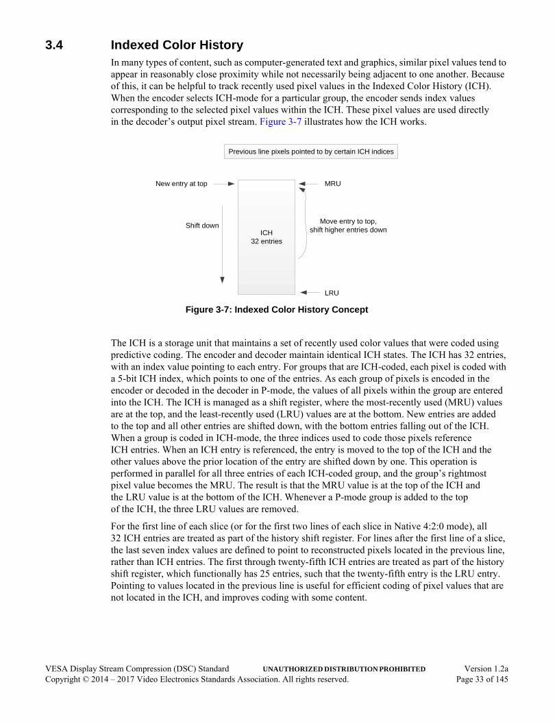
3.4 Indexed Color HistoryIn many types of content, such as computer-generated text and graphics, similar pixel values tend to appear in reasonably close proximity while not necessarily being adjacent to one another. Because of this, it can be helpful to track recently used pixel values in the Indexed Color History (ICH). When the encoder selects ICH-mode for a particular group, the encoder sends index values corresponding to the selected pixel values within the ICH. These pixel values are used directly in the decoder’s output pixel stream. Figure 3-7 illustrates how the ICH works.
Figure 3-7: Indexed Color History Concept
The ICH is a storage unit that maintains a set of recently used color values that were coded using predictive coding. The encoder and decoder maintain identical ICH states. The ICH has 32 entries, with an index value pointing to each entry. For groups that are ICH-coded, each pixel is coded with a 5-bit ICH index, which points to one of the entries. As each group of pixels is encoded in the encoder or decoded in the decoder in P-mode, the values of all pixels within the group are entered into the ICH. The ICH is managed as a shift register, where the most-recently used (MRU) values are at the top, and the least-recently used (LRU) values are at the bottom. New entries are added to the top and all other entries are shifted down, with the bottom entries falling out of the ICH. When a group is coded in ICH-mode, the three indices used to code those pixels reference ICH entries. When an ICH entry is referenced, the entry is moved to the top of the ICH and the other values above the prior location of the entry are shifted down by one. This operation is performed in parallel for all three entries of each ICH-coded group, and the group’s rightmost pixel value becomes the MRU. The result is that the MRU value is at the top of the ICH and the LRU value is at the bottom of the ICH. Whenever a P-mode group is added to the top of the ICH, the three LRU values are removed.
For the first line of each slice (or for the first two lines of each slice in Native 4:2:0 mode), all 32 ICH entries are treated as part of the history shift register. For lines after the first line of a slice, the last seven index values are defined to point to reconstructed pixels located in the previous line, rather than ICH entries. The first through twenty-fifth ICH entries are treated as part of the history shift register, which functionally has 25 entries, such that the twenty-fifth entry is the LRU entry. Pointing to values located in the previous line is useful for efficient coding of pixel values that are not located in the ICH, and improves coding with some content.
ICH32 entries
MRU
LRU
Shift downMove entry to top,
shift higher entries down
New entry at top
Previous line pixels pointed to by certain ICH indices
VESA Display Stream Compression (DSC) Standard UNAUTHORIZED DISTRIBUTION PROHIBITED Version 1.2aCopyright © 2014 – 2017 Video Electronics Standards Association. All rights reserved. Page 33 of 145

The encoder selects ICH-mode on a per-group basis. The encoder signals the use of ICH-mode for a group in the luma substream using an escape code. For each group coded in ICH-mode, each pixel within the group is coded using a fixed-length 5-bit code, where the index values point into the history.
To decode an ICH-coded group, first the decoder determines the use of ICH-mode by way of the syntax in use, and then decodes each pixel within the group by reading the values pointed to by the ICH indices that constitute the coded values of the pixels. The encoder and decoder both update the ICH state in an identical manner. The updates occur every group, by inserting P-mode pixels into the ICH and re-ordering the ICH entries in response to ICH-mode groups.
3.5 Bitstream ConstructionThis Standard defines syntax at multiple layers. The lowest layer is the Substream Layer. There are three or four substreams within each slice, one for each component. The three or four substreams are multiplexed together by the SSM process to form a coded slice. If there is more than one slice per line, the coded slices are multiplexed by the slice multiplexing process. The resulting bits of all slices are concatenated to form a coded picture. Each coded picture is optionally preceded by a PPS. There is at least one picture, up to an unlimited number of pictures. The result of all these operations is the DSC bitstream.
3.5.1 Substream LayerDSC encodes prediction residuals, using the DSU-VLC entropy coding scheme, as listed in Table 3-1. ICH coding of pixels uses a fixed-length code for each pixel. Specialized values are used to signal ICH-mode use, and other codes signal quantization adjustments associated with flat regions of pixels.
Table 3-1: Examples of Sizes for Different Residual ValuesUsed in Delta Size Unit-Variable Length Coding
ResidualValues
Size(Bits)
Representation
-3 3 101b
-2 2 10b
-1 1 1b
0 0 <none>
1 2 01b
2 3 010b
3 3 011b
VESA Display Stream Compression (DSC) Standard UNAUTHORIZED DISTRIBUTION PROHIBITED Version 1.2aCopyright © 2014 – 2017 Video Electronics Standards Association. All rights reserved. Page 34 of 145

The pixels within each slice are organized into groups of three consecutive pixels each. A group is a logical construct used by the encoding and decoding processes; however, groups are not directly represented in the bitstream due to the SSM process. DSU-VLC organizes samples into units. A unit is the coded set of residuals comprised of three consecutive samples of one component (i.e., one component of a group). Each unit has two parts – a prefix and residual. The size of each residual is predicted, based on the size of the residuals (see Table 3-1 for examples) in the previous unit of the same component (i.e., the three previous residuals) and any change in quantization parameter (QP) that might have occurred since that preceding unit. The prefix is a unary code that indicates the non-negative difference between the size of the largest residual in the unit and the predicted size. If the difference is negative, the prefix codes a value of 0. The residual portion of each group contains three values, one for each sample within the unit. The residual values are coded in two’s complement. All three residuals within one unit are allocated the same number of bits. The number of bits allocated to residuals can vary from unit to unit.
In the coding scheme, a quantized residual size equal to the component’s bit depth minus the quantization level indicates that MPP is selected. Therefore, MMAP or BP cannot be used for a particular component if the resulting quantized residuals have a size greater than or equal to the component bit depth minus the quantization level. Instead, the encoder selects MPP, where all quantized residuals are “0” bit-padded or sign-extended, as needed, to a size of bit depth minus quantization level.
In addition, the prefix for the first unit of a group also indicates whether ICH-mode is used for that group. A transition from P-mode to ICH-mode is indicated by an escape code (i.e., a prefix value that indicates a size that is one greater than the maximum possible residual size for luma). The maximum possible residual size for luma depends on the QP value that applies to luma within the group. An ICH-mode group immediately following another ICH-mode group is indicated by a luma prefix code consisting of a single “1” bit. A P-mode group immediately following an ICH-mode group is indicated by a modified unary code.
For an ICH-mode group, the residual portion is a 5-bit fixed-length code that represents an ICH index that codes the samples for a complete pixel. Only the first unit has a prefix for an ICH-coded group.
For subsequent ICH-mode groups following an initial ICH-mode group, each group uses 16 bits for every group (i.e., a 1-bit “1” prefix and three 5-bit ICH codes, one in each substream).
Note: The resulting 5.333 bits/pixel can constrain the minimum possible bit rate achievable with DSC. In Native 4:2:0 and 4:2:2 modes, each group represents six pixels, so the corresponding minimum bit rate in that mode is 2.667 bits/pixel.
The first luma substream also contains some conditional fixed-length codes within the syntax, which allows the encoder to convey information about a transition from a busy to smooth area. Section 6.8.5 discusses this “flatness indication” in further detail.
VESA Display Stream Compression (DSC) Standard UNAUTHORIZED DISTRIBUTION PROHIBITED Version 1.2aCopyright © 2014 – 2017 Video Electronics Standards Association. All rights reserved. Page 35 of 145

3.5.2 Substream MultiplexingThe three or four single-component substreams are multiplexed together, using substream multiplexing (SSM). SSM uses fixed-length mux words and no headers. Figure 3-8 illustrates an example of SSM results for an 8 or 10bpc RGB picture.
Figure 3-8: Example of Slice Layer Multiplexing Output
Each mux word has an identical size (muxWordSize) – 48 bits for 8 or 10bpc, or 64 bits for 12, 14, or 16bpc. The mux word order is derived from the order in which parallel substream decoders need the data to decode in real time, as illustrated in Figure 3-9.
Figure 3-9: Example of Substream Demultiplexing
The combination of a funnel shifter and VLD is referred to as a “substream processor” (SSP). At each group time, any combination of the SSPs can request a mux word or none at all. If a request is received from an SSP, the demultiplexer sends a mux word to that SSP. If multiple requests are received within the same group time, the demultiplexer sends a mux word to each SSP that made a request, in the order requested.
At the end of the slice, each SSP could request a mux word beyond the end of the substream data. This is because the SSP loads a mux word into its funnel shifter whenever the funnel shifter has sufficient space, which accounts for the possibility that the last one or few units of a slice could use the maximum possible number of bits. Therefore, the encoder might insert one or more empty mux words near the end of the slice that correspond to SSP requests from finished substreams.
Y Co Cg Y Y Co Y Co Cg Y Co Y Cg
Mux words inserted anddemultiplexed thereafter, as needed
One mux word per componentat start of slice
Mux words @ 48 bits.In this example, Y uses more bits than Co, which uses more bits than Cg.
Demultiplexer places a mux word into each funnel shifter when the funnel shifter has sufficient space for a mux word.
Can demultiplex 0, 1, 2, or 3 mux words within each clock cycle.
Funnel Shifter and Entropy Decoder
Rate Buffer RAM DemultiplexerBitstream Funnel Shifter
and Entropy Decoder
Funnel Shifter and Entropy Decoder
Y
Co
Cg
VESA Display Stream Compression (DSC) Standard UNAUTHORIZED DISTRIBUTION PROHIBITED Version 1.2aCopyright © 2014 – 2017 Video Electronics Standards Association. All rights reserved. Page 36 of 145

The encoding SSM process uses a model of the decoder SSM demultiplexer to correctly order the mux words. Balance FIFOs store many groups worth of data so that each mux word can be inserted into the bitstream in the correct order. For example, if one component’s substream is coded with 1 bit/unit, the encoding process must code a number of groups equal to the mux word size to generate a first mux word for that component. Depending on the mux word ordering, the other components might need to temporarily store a similar number of coded units, each of which could potentially use the maximum possible number of bits before the SSM can process the mux words from those other components. The calculation of the maximum possible Balance FIFO occupancy is a little more involved, and is reflected in the encoding processing described in Section 6.7.1.
The use of Balance FIFOs in the SSM process introduces latency into the encoding process. As long as the encoding process precisely follows the specified algorithm, the encoder’s output should conform to this Standard and should be interoperable with conforming decoders. For further details regarding the effect of SSM and Balance FIFOs on timing, see Section 3.7.
Figure 3-10: Example of Substream Multiplexing
Multiplexer places a mux word from each substream into the bitstream when its model of the decoder funnel shifter has sufficient space for a mux word.
Can multiplex 0, 1, 2, or 3 mux words within each clock cycle.
VLC andFunnel Shifter
Rate Buffer RAMMultiplexerBitstream
VLC and
Funnel Shifter
VLC andFunnel Shifter
Y
Co
Cg
BalanceFIFO
Balance
FIFO
BalanceFIFO
DemultiplexerModel
Multiplexing ControlStream Information
VESA Display Stream Compression (DSC) Standard UNAUTHORIZED DISTRIBUTION PROHIBITED Version 1.2aCopyright © 2014 – 2017 Video Electronics Standards Association. All rights reserved. Page 37 of 145

3.6 Rate ControlThe encoder and decoder use identically configured rate control (RC) algorithms. Decisions made by the RC algorithm to adjust quantization parameters (QP) in the encoder are mimicked in the decoder, such that the decoder has the same QP value as the encoder at every pixel. No bits are spent communicating the QP value except for the flatness indication. RC decisions are made in the encoder and decoder based on previously transmitted and received information. respectively. The RC algorithm can change the QP value for each group.
The RC algorithm is designed with several goals in mind:
• Provide the encoder and decoder with the QP to use for each group. Because the RC algorithm is the same on both the encoder and decoder sides, the base QP value is known to both the encoder and decoder and does not need to be transmitted in the bitstream, with the exception of indicating flatness as described in Section 6.8.5.
• Ensure hypothetical reference decoder (HRD) conformance. RC incorporates a model of an idealized rate buffer (which behaves like a FIFO) that converts a varying number of bits to code for each group into a specified constant bit rate. The RC algorithm guarantees that this model neither overflows nor underflows. This ensures that a real rate buffer within an encoder neither overflows nor underflows, as long as bits are removed from the rate buffer at the specified constant bit rate.
The RC algorithm is designed to optimize subjective picture quality by way of its QP decisions. It is desirable to use a lower QP on relatively flat areas, and a higher QP on busy areas because errors are less perceptible in busy areas. It is also desirable to maintain a constant quality for all pixels (e.g., the first line of a slice has limited prediction, and therefore requires an additional bit allocation). Table 3-2 describes the RC components. The RC algorithm is specified in detail in Section 6.8.
Table 3-2: Rate Control Components
Component Description
Buffer Tracker Keeps track of the modeled buffer fullness, which is the hypothetical fullness of an encoder rate buffer assuming that the buffer behaves in an ideal way.
Linear Transformation Converts the fullness to a normalized value for the remainder of the model, handling the initial transmission delay and extra bit allocation for the first lines of each slice.
Long-term RC Converts the transformed buffer fullness into parameters that are used by the short-term RC (i.e., minimum QP, maximum QP and target bits/group adjustment).
Short-term RC Adjusts the QP on a group-by-group basis.
Flatness Adjustment Provides a means for the encoder to rapidly drop the QP if the upcoming pixels are relatively flat.
VESA Display Stream Compression (DSC) Standard UNAUTHORIZED DISTRIBUTION PROHIBITED Version 1.2aCopyright © 2014 – 2017 Video Electronics Standards Association. All rights reserved. Page 38 of 145
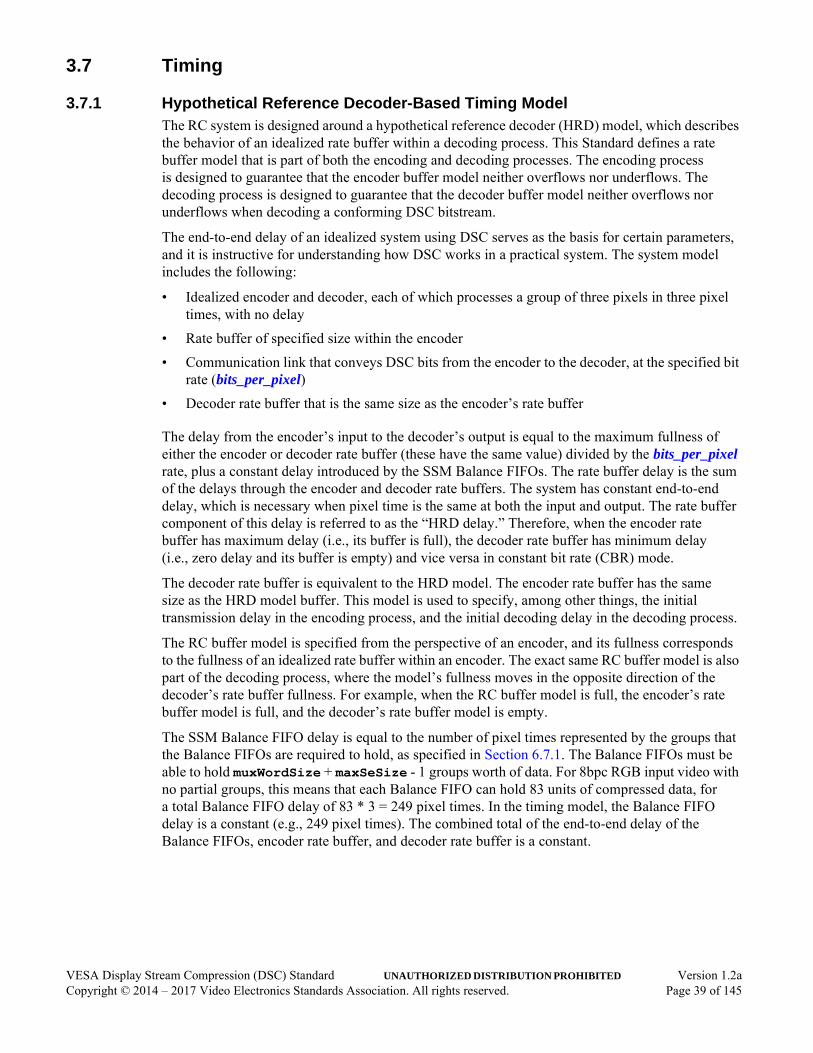
3.7 Timing
3.7.1 Hypothetical Reference Decoder-Based Timing ModelThe RC system is designed around a hypothetical reference decoder (HRD) model, which describes the behavior of an idealized rate buffer within a decoding process. This Standard defines a rate buffer model that is part of both the encoding and decoding processes. The encoding process is designed to guarantee that the encoder buffer model neither overflows nor underflows. The decoding process is designed to guarantee that the decoder buffer model neither overflows nor underflows when decoding a conforming DSC bitstream.
The end-to-end delay of an idealized system using DSC serves as the basis for certain parameters, and it is instructive for understanding how DSC works in a practical system. The system model includes the following:
• Idealized encoder and decoder, each of which processes a group of three pixels in three pixel times, with no delay
• Rate buffer of specified size within the encoder
• Communication link that conveys DSC bits from the encoder to the decoder, at the specified bit rate (bits_per_pixel)
• Decoder rate buffer that is the same size as the encoder’s rate buffer
The delay from the encoder’s input to the decoder’s output is equal to the maximum fullness of either the encoder or decoder rate buffer (these have the same value) divided by the bits_per_pixel rate, plus a constant delay introduced by the SSM Balance FIFOs. The rate buffer delay is the sum of the delays through the encoder and decoder rate buffers. The system has constant end-to-end delay, which is necessary when pixel time is the same at both the input and output. The rate buffer component of this delay is referred to as the “HRD delay.” Therefore, when the encoder rate buffer has maximum delay (i.e., its buffer is full), the decoder rate buffer has minimum delay (i.e., zero delay and its buffer is empty) and vice versa in constant bit rate (CBR) mode.
The decoder rate buffer is equivalent to the HRD model. The encoder rate buffer has the same size as the HRD model buffer. This model is used to specify, among other things, the initial transmission delay in the encoding process, and the initial decoding delay in the decoding process.
The RC buffer model is specified from the perspective of an encoder, and its fullness corresponds to the fullness of an idealized rate buffer within an encoder. The exact same RC buffer model is also part of the decoding process, where the model’s fullness moves in the opposite direction of the decoder’s rate buffer fullness. For example, when the RC buffer model is full, the encoder’s rate buffer model is full, and the decoder’s rate buffer model is empty.
The SSM Balance FIFO delay is equal to the number of pixel times represented by the groups that the Balance FIFOs are required to hold, as specified in Section 6.7.1. The Balance FIFOs must be able to hold muxWordSize + maxSeSize - 1 groups worth of data. For 8bpc RGB input video with no partial groups, this means that each Balance FIFO can hold 83 units of compressed data, for a total Balance FIFO delay of 83 * 3 = 249 pixel times. In the timing model, the Balance FIFO delay is a constant (e.g., 249 pixel times). The combined total of the end-to-end delay of the Balance FIFOs, encoder rate buffer, and decoder rate buffer is a constant.
VESA Display Stream Compression (DSC) Standard UNAUTHORIZED DISTRIBUTION PROHIBITED Version 1.2aCopyright © 2014 – 2017 Video Electronics Standards Association. All rights reserved. Page 39 of 145

In practice, the Balance FIFO delay is not exactly constant because there is a small variation term that is the direct result of grouping compressed bits into mux words (e.g., 48 bits), and there is a complement variation term in the decoder, for the same reason. However, this does not affect the end-to-end delay because the initial delay (i.e., at the start of the slice) sets the constant end-to-end delay. In a practical encoder, the compressed bits can be distributed anywhere between the Balance FIFOs and rate buffer, as long as the function conforms to this Standard. A decoder delays its start for a specified time (initial_dec_delay), during which bits accumulate within the decoder’s rate buffer. After decoding starts, mux words are moved from the rate buffer to the entropy decoder, as required, without necessarily introducing any delay.
The initial transmission delay refers to the delay after the compressed bits enter the encoder’s rate buffer model (i.e., after the Balance FIFOs and SSM and before beginning slice transmission). The total delay through the encoder is greater than this by the Balance FIFO delay, plus any implementation delays.
In constant bit rate (CBR) mode, the HRD model fullness is equal to the HRD buffer size minus the encoder buffer fullness; therefore, the decoder buffer model is guaranteed to neither overflow nor underflow. In variable bit rate (VBR) mode (i.e., bit rate drops to 0 when the encoder buffer becomes empty), the HRD fullness can be less than the HRD buffer size minus encoder buffer fullness; however, the decoder buffer model still neither overflows nor underflows. CBR and VBR modes are described in Section 3.7.2.
The DSC encoder rate buffer model defines a schedule for bits entering and leaving the rate buffer:
• During an initial transmission delay (specified by initial_xmit_delay), the encoder generates a number of bits every pixel time, as described in Section 6.6, then places the bits into its Balance FIFO. From there, the encoder moves the bits into its rate buffer after the SSM process and associated Balance FIFO delay; however, no bits are removed. During this period, the encoder model fullness increases according to the number of bits that are produced. The delay period is specified in units of pixel time.
• As long as there are more pixels in the slice that need to be encoded, the encoder generates bits according to its content. Bits are removed at the specified constant rate. The usual prediction method selection is overridden with MPP when the buffer fullness is sufficiently low in CBR mode. MPP guarantees a minimum data rate, which prevents the buffer fullness from dropping below 0.
• After the last group within a slice is encoded, no more bits are added to the rate buffer. Bits continue to leave the rate buffer at the constant rate, until the buffer becomes empty. In CBR mode, the encoder sends “0” padding bits afterward to ensure that the compressed slice size, in units of bits, is equal to the slice bit budget (sliceBits, described in Table E-1).
The decoder accumulates bits within its rate buffer for a period of time before starting to decode the bits. This initial decoding delay specified by initial_dec_delay is the complement of the encoder initial delay (i.e., the HRD delay minus the encoder’s initial transmission delay). The decoder rate buffer fullness then tracks as the complement of the encoder buffer fullness.
VESA Display Stream Compression (DSC) Standard UNAUTHORIZED DISTRIBUTION PROHIBITED Version 1.2aCopyright © 2014 – 2017 Video Electronics Standards Association. All rights reserved. Page 40 of 145

Note: The Balance FIFO latency might be relevant in practical system designs. In an example encoder architecture, the SSM’s output is the input to the encoder’s rate buffer, where the rate buffer is a real buffer, which is not necessarily the same as the rate buffer model in the Standard. The SSM process and associated Balance FIFOs add latency to the encoding process. This does not affect the rate buffer model behavior or the required rate buffer size. The initial_xmit_delay applies after the initial Balance FIFO delay. The Balance FIFO latency does not affect the encoded bitstream or the decoder behavior. However, in typical architectures, Balance FIFO latency does affect end-to-end system latency.
3.7.2 Constant and Variable Bit Rate ModesThe DSC encoding process can operate in either constant bit rate (CBR) or variable bit rate (VBR) mode. In CBR mode, the bit rate is specified in units of bits per pixel time, which is constant and equal to the specified bits_per_pixel rate. In VBR mode, the bit rate at any pixel time is either the specified bits_per_pixel rate or 0. The rate is typically the bits_per_pixel rate and changes to 0 when necessary to avoid encoder buffer model underflow. Application specifications should make the choice of whether to use CBR or VBR mode.
The practical effect of the CBR vs. VBR mode design choice is seen in what the encoding process does when conditions exist that would otherwise cause the encoder rate buffer to underflow. To avoid underflow in CBR mode, the encoder artificially increases the number of bits used.
To avoid underflow in CBR mode, the RC algorithm determines whether underflow is possible after the next coded group. This condition forces selection of MPP, which guarantees a minimum bit rate. The decoder does not require any special logic to handle bit stuffing because the decoder simply decodes the extra bits the same as it would for any other group.
To avoid underflow in VBR mode, the encoder stops sending bits when the encoder would otherwise underflow and has no bits to send. Specifically, the encoder’s RC algorithm operates once per group. At each group, the RC algorithm adds to the buffer model the number of bits that code the group, subtracts the nominal number of bits per group from the buffer model (3 * bits_per_pixel), and then adjusts, as necessary, to be an integer number of bits. With VBR, if this subtraction of bits/group from the buffer model fullness would result in a negative value of fullness, the RC algorithm subtracts the nominal number of bits, and then clamps the buffer fullness to 0 (i.e., the model fullness is never allowed to be negative).
In a real system, with a real transport and decoder, when the encoder has no more bits to send (i.e., its real rate buffer is empty), the transport does not send any bits and the decoder does not receive any bits. The decoder’s real rate buffer might be full; however, the buffer does not overflow. When the encoder has bits to send, the transport is expected to transmit the bits at the usual rate, and the decoder receives the bits at that rate. The decoder’s real buffer neither overflows nor underflows, and the decoder does not have to do anything special to handle VBR mode. The transport must, however, must be able to determine when valid data is available to send and receive.
VBR does have an effect on the formal HRD constraint and end-to-end buffer model. The effects on the HRD are discussed in Annex F. Regarding the end-to-end buffer model, because VBR sometimes enables the bit rate to be 0, the average effective bit rate can be significantly reduced as compared to the nominal bits_per_pixel rate. As a result, the total sum fullness of the encoder and decoder idealized rate buffers can be less than the buffer model size. For example, the encoder buffer might be empty and the decoder buffer might be significantly less than full.
VESA Display Stream Compression (DSC) Standard UNAUTHORIZED DISTRIBUTION PROHIBITED Version 1.2aCopyright © 2014 – 2017 Video Electronics Standards Association. All rights reserved. Page 41 of 145

3.7.3 Slices and TimingIn CBR mode, DSC operation requires that the number of bits that code a picture be equal to the number of pixels in that picture times the specified bits_per_pixel rate. Furthermore, DSC requires support for slices, where any subset of slices of a picture can be updated in place within a compressed frame buffer by overwriting the previous version of each of the corresponding slices. A picture can be transmitted as a series of consecutive slices comprising the entire picture, and an entire picture transmitted as a series of consecutive slices must meet the same requirement as for slices (i.e., for both the entire picture and each individual slice, the number of bits equals the number of pixels times the bits_per_pixel rate). In addition, the entire picture’s slices must conform to an appropriate HRD model to ensure correct real-time buffer behavior with this mode of operation. Therefore, the delay from the start of transmission to the start of decoding, and the delay from the end of transmission to the end of decoding, must be the same as one another, and the same for each slice. By design, DSC guarantees that these requirements are met.
The RC algorithm uses a rate buffer. The algorithm is designed to allow the encoder’s rate buffer to have up to a specified fullness (i.e., a maximum number of bits) at the end of each slice. In CBR mode, if the encoder’s buffer has fewer bits at the end of coding a slice than this maximum number, the encoder stuffs “0” padding bits at the end of the slice to produce the required number of bits. The total number of bits (including the stuffed bits) remaining in the encoder’s rate buffer at the end of a slice occupies a specified number of pixel times to transmit at the specified bits_per_pixel rate. This number of pixel times is the delay from the end of encoding to the end of transmission, which can be referred to as the “final transmission delay.” The total rate buffer delay, in units of pixel time, in a combined idealized encoder and decoder is equal to the rate buffer size divided by the bits_per_pixel rate. The initial transmission delay (i.e., from the start of encoding a slice until the start of transmitting that slice) is the same as the final transmission delay. The initial decoding delay (i.e., the delay in the HRD from the start of receiving a slice to the start of decoding that slice) is set equal to the total end-to-end rate buffer delay minus the initial transmission delay. This guarantees correct operation, per the requirements outlined above.
The RC algorithm has a parameter value for the maximum number of bits that can be in the encoder buffer at the end of a slice, typically approximately 4kbits. The ending transmission delay is a function of the bits_per_pixel rate; assuming the value is 4096 bits, the rate is roughly 4096 / bits_per_pixel. At 8bpp, this delay is 512 pixel times, and at 12bpp, this delay is 341 pixel times. The actual value of this parameter – the maximum number of bits at the end of a slice – is determined from the initial_xmit_delay parameter. The initial_xmit_delay value is the same as the ending transmission delay described here.
VESA Display Stream Compression (DSC) Standard UNAUTHORIZED DISTRIBUTION PROHIBITED Version 1.2aCopyright © 2014 – 2017 Video Electronics Standards Association. All rights reserved. Page 42 of 145

The end-to-end HRD delay is equal to the HRD buffer size divided by the bits_per_pixel rate. For example, if the HRD buffer size is 19836 bits and the rate is 12bpp, the end-to-end HRD delay is as follows:
ceil(19836 / 12) = 1653 pixel times
The initial decoding delay, which applies directly to the HRD and indirectly to real decoders, should be set to the HRD delay minus the initial transmission delay. In the example provided here, where the initial transmission delay is set to 341 pixel times as above, the initial decoding delay is as follows:
1653 - 341 = 1312 pixel times
This is a delay that applies to the HRD (i.e., an idealized hypothetical decoder). A real decoder is able to have additional delay. Additional decoder delay and buffering capacity can be required in some applications, due to differences between the idealized transport schedule used in the HRD model and the real transport schedule used in the application.
The rate buffer size is a function of several factors, including the bits_per_pixel rate and width of slices. The formula used to determine the rate buffer size is provided in Annex E. Some configurations of multiple slices per line do not require additional buffering, such as the example illustrated in Figure 3-11. However, some configurations might require additional buffering, as described in Annex G.
In a practical system that uses multiple slices per picture, where the slices are consecutively transmitted and received, the encoder and decoder rate buffers (i.e., actual buffers, not algorithmic buffer models) can contain data from more than one slice, due to the buffer model delays and the associated overlap between transmitting bits for one slice while decoding the previous slice or encoding the next slice. Although data from more than one slice might be present, the rate buffer size needed in an encoder or decoder for vertically adjacent slices is no larger than would be necessary for a single slice.
In an encoder, at the beginning of a slice, the encoder buffer model is empty, and the rate buffer has up to roughly 4096 bits (in general, initial_xmit_delay * bits_per_pixel bits) remaining to transmit from the previous slice. Assuming that the slice width is greater than the initial_xmit_delay, during the transition time (i.e., while bits from the previous slice are waiting to be transmitted, and bits from the current slice are being added to the rate buffer), the maximum net accumulation of bits from the new slice is bounded by the rate control to be no larger than the following:
rc_model_size - initial_offset + (first_line_bpg_offset + pixelsPerGroup * bits_per_pixel) * number of groups processed
The number of bits remaining in the buffer from the previous slice is bounded by the following:
MAX(0, 4096 - pixelsPerGroup * bits_per_pixel) * number of groups
where:
• pixelsPerGroup is 3, regardless of mode (4:4:4, Native or Simple 4:2:2, –or– Native 4:2:0)
• number of groups is the same number of groups from the new slice processed by the encoder
VESA Display Stream Compression (DSC) Standard UNAUTHORIZED DISTRIBUTION PROHIBITED Version 1.2aCopyright © 2014 – 2017 Video Electronics Standards Association. All rights reserved. Page 43 of 145

The sum of these numbers of bits is equal to the following:
rc_model_size - initial_offset + 4096 + first_line_bpg_offset * number of groups
The rate buffer is assumed to be at least as large as the buffer model, which is specified to be as follows:
rc_model_size - initial_offset + ceil(initial_xmit_delay * bits_per_pixel) + groupsPerLine * first_line_bpg_offset
Note: groupsPerLine is described in Table E-1.
Because of this, it is impossible for the sum to exceed the rate buffer size. A similar analysis holds true for the case in which the slice width is smaller than the initial_xmit_delay.
On the decoder side, the overlap time occurs just before the end of a first slice while a second slice is arriving into the buffer. During the initial_dec_delay pixel times since the start of arrival of bits from the second slice, the decoder rate buffer fills up with data for the second slice while the decoder rate buffer might still have bits from the first slice. In the worst case, the last group of the first slice has approximately 4096 bits (i.e., initial_xmit_delay * bits_per_pixel bits) due to the stuffing of “0” padding bits at the end of the slice. The time during the overlap when the maximum decoder buffer fullness occurs is just before decoding the last group of the first slice (i.e., just before initial_dec_delay pixel times) after the start of receiving the second slice. During this interval, the decoder does not remove any bits associated with the second slice because the first pixel of the second slice is decoded after the last pixel of the first slice. At this time, the decoder buffer has received just under initial_dec_delay * bits_per_pixel bits. The sum of these two components of fullness is less than or equal to (initial_xmit_delay + initial_dec_delay) * bits_per_pixel bits, which is equal to the buffer model size. As long as the decoder rate buffer size is greater than or equal to the buffer model size, the decoder buffer fullness during the overlap cannot exceed the rate buffer size.
VESA Display Stream Compression (DSC) Standard UNAUTHORIZED DISTRIBUTION PROHIBITED Version 1.2aCopyright © 2014 – 2017 Video Electronics Standards Association. All rights reserved. Page 44 of 145
3.8 Options for SlicesDSC is configurable to support a wide variety of slice widths and heights. The following two sample configurations are appropriate for real system usage:
slice_width = ¼ pic_width; slice_height = 108 lines
slice_width = pic_width; slice_height = 108 lines
The slice dimensions can be specified up to the picture width by the picture height. To minimize extra data that might need to be sent, systems can select pic_width and pic_height to be evenly divisible by slice_width and slice_height, respectively.
Taller slices allow for better compression, with diminishing returns. Extra bits are allocated to the first line of each slice to maximize quality and avoid creating artifacts at the boundaries between slices. The number of extra bits allocated per group on the first line is set by a PPS parameter. The number of bits available to all lines after the first line within each slice must be reduced to meet the requirement that the total number of bits per slice must be equal to the number of pixels times the bits_per_pixel rate. The need to reduce bit allocation decreases as the number of lines within the slice increases. For example, a slice height of 108 lines typically provides better performance than a slice height of 8 lines. There is no cost associated with slice height because there is no additional buffering or any other additional resources required. Among other things, DSC supports a slice size equal to the entire picture size. This configuration can be desirable in some applications. However, taller slices also create potentially larger partial update sizes and have more visible impact for bit errors.
Slices narrower than full screen width can be desirable for various practical purposes. Some possible motivations include the ability to update a narrower slice by way of partial update, or to facilitate parallel processing within one image. In practice, multiple slices per line can use one line buffer that is equal to the picture width. With multiple slices per line, there are separate rate buffers for each of the different columns of slices within a picture. For example, with four slices per line, there are four rate buffers. The size of each rate buffer is determined in part by the slice width. For example, the total size of the rate buffers for the case of 4 slices/line is less than four times the size of a rate buffer for the case of 1 slice/line. Some additional buffering and hardware might also be needed; therefore, it is generally desirable to limit the number of slices per line.
Note: A display image can be divided into multiple independent subimages, each being processed by a separate DSC instance. Such a configuration might be desirable, for example, with system designs that have separate devices for separate regions of a display, with each device having a separate link and DSC decoder. Such independent subimages can be encoded in parallel and decoded in parallel. In this case, because these are separate images, the subimages do not need to use multiple slices per line in the context of DSC.
VESA Display Stream Compression (DSC) Standard UNAUTHORIZED DISTRIBUTION PROHIBITED Version 1.2aCopyright © 2014 – 2017 Video Electronics Standards Association. All rights reserved. Page 45 of 145

3.9 Slice MultiplexingIn systems configured to use more than one slice per scan line, the compressed data is multiplexed according to a specific pattern to minimize implementation costs in both encoders and decoders. The pattern is as follows – for a picture width of W pixels and an integer number of S slices per line, each slice has P pixels per line. P is equal for all slices. When W/S is an integer, P is equal to W/S. However, when W/S is not an integer, P is equal to ceil(W/S) and the last slice of the line is padded with replicated pixels so that P is equal for the different columns of slices within a picture.
The multiplexed bitstream contains a series of chunks. The first chunk has ceil(P * bits_per_pixel rate / 8) bytes for the first slice of the first row of slices. The second chunk has ceil(P * bits_per_pixel rate / 8) bytes for the second slice of the first row of slices, and so forth for each slice within the first row of slices. One iteration of this pattern (i.e., all the chunks of one line) has S * ceil(P * bits_per_pixel rate / 8) bytes. This pattern then repeats with as many chunks as are needed to transmit all the bits for the first row of slices. The process repeats for all rows of compressed slice lines within the picture. An application specification (e.g., a transport specification that is designed to carry DSC compressed image data) can have additional constraints, such as the number of bits per line of a slice might need to be an integer multiple of some larger word size (e.g., 16 bits, 24 bits, etc.).
A transport can be designed to carry data from different slices, in separate packets. In this case, the last bits from one slice are in a separate packet from those of all other slices, including the first bits of the vertically adjacent slice immediately below the first slice. The DSC bitstream does not contain markers or other identifiers indicating which bits are for which slice nor the locations of the first bits of each slice within the bitstream – those are the responsibility of the Transport Layer, which is outside the scope of this Standard.
Figure 3-11 illustrates an example of the buffering and decoding timing in a decoder that is receiving a stream with two slices per line multiplexed, and sequentially decoding pixels in raster scan order.
An encoder that produces more than 1 slice/line, and hence implements slice multiplexing, should also take into account the implications of slice multiplexing on the timing of encoder operations and the associated buffering requirements. The implications might be similar to those of the decoder slice timing illustrated in Figure 3-11.
Figure 3-11: Decoder Slice Timing and Delays for Two Slices/Line
Slice transmission timing
Left chunk 1 Right chunk 1 Left chunk 2
Left slice line 1 part 1
Right chunk 2 Left chunk 3
Left slice line 1 part 2
Right slice line 1 part 1
Right slice line 1 part 2
initial_dec_delay initial_dec_delay
Left sliceline 2 part 2
Left slice line 2 part 1Part 1 delayed
to be contiguous with part 2
initial_dec_delay
SSM demultiplexing delay at start of slice is effectively 0
VESA Display Stream Compression (DSC) Standard UNAUTHORIZED DISTRIBUTION PROHIBITED Version 1.2aCopyright © 2014 – 2017 Video Electronics Standards Association. All rights reserved. Page 46 of 145
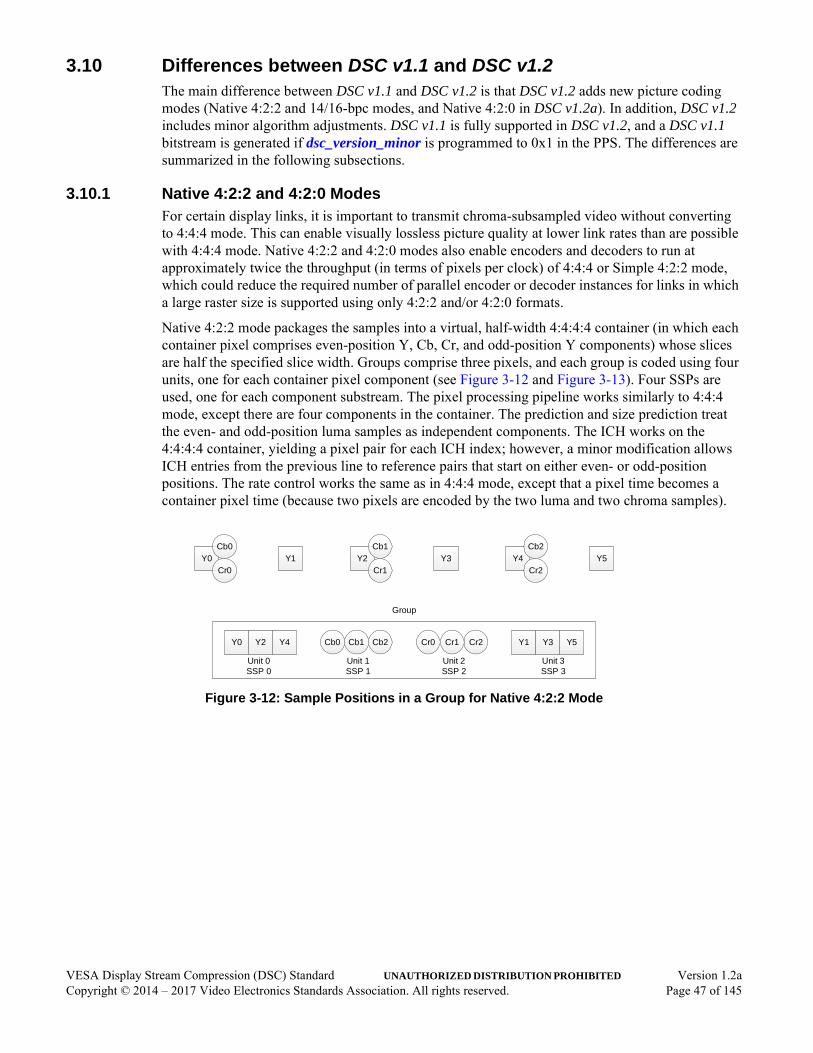
3.10 Differences between DSC v1.1 and DSC v1.2The main difference between DSC v1.1 and DSC v1.2 is that DSC v1.2 adds new picture coding modes (Native 4:2:2 and 14/16-bpc modes, and Native 4:2:0 in DSC v1.2a). In addition, DSC v1.2 includes minor algorithm adjustments. DSC v1.1 is fully supported in DSC v1.2, and a DSC v1.1 bitstream is generated if dsc_version_minor is programmed to 0x1 in the PPS. The differences are summarized in the following subsections.
3.10.1 Native 4:2:2 and 4:2:0 ModesFor certain display links, it is important to transmit chroma-subsampled video without converting to 4:4:4 mode. This can enable visually lossless picture quality at lower link rates than are possible with 4:4:4 mode. Native 4:2:2 and 4:2:0 modes also enable encoders and decoders to run at approximately twice the throughput (in terms of pixels per clock) of 4:4:4 or Simple 4:2:2 mode, which could reduce the required number of parallel encoder or decoder instances for links in which a large raster size is supported using only 4:2:2 and/or 4:2:0 formats.
Native 4:2:2 mode packages the samples into a virtual, half-width 4:4:4:4 container (in which each container pixel comprises even-position Y, Cb, Cr, and odd-position Y components) whose slices are half the specified slice width. Groups comprise three pixels, and each group is coded using four units, one for each container pixel component (see Figure 3-12 and Figure 3-13). Four SSPs are used, one for each component substream. The pixel processing pipeline works similarly to 4:4:4 mode, except there are four components in the container. The prediction and size prediction treat the even- and odd-position luma samples as independent components. The ICH works on the 4:4:4:4 container, yielding a pixel pair for each ICH index; however, a minor modification allows ICH entries from the previous line to reference pairs that start on either even- or odd-position positions. The rate control works the same as in 4:4:4 mode, except that a pixel time becomes a container pixel time (because two pixels are encoded by the two luma and two chroma samples).
Figure 3-12: Sample Positions in a Group for Native 4:2:2 Mode
Cr0 Cr1 Cr2
Unit 2SSP 2
Y0Cb0
Cr0Y1 Y2
Cb1
Cr1Y3 Y4
Cb2
Cr2Y5
Y0 Y2 Y4 Cb0 Cb1 Cb2
Group
Unit 0SSP 0
Unit 1SSP 1
Y1 Y3 Y5
Unit 3SSP 3
VESA Display Stream Compression (DSC) Standard UNAUTHORIZED DISTRIBUTION PROHIBITED Version 1.2aCopyright © 2014 – 2017 Video Electronics Standards Association. All rights reserved. Page 47 of 145

Figure 3-13: Mapping of 4:2:2/4:2:0 Picture to 4:4:4:4/4:4:4 Container
Native 4:2:0 mode (see Figure 3-13 and Figure 3-14) packages the samples into a virtual, half-width 4:4:4 container (in which each container pixel comprises even-position Y, Cb, Cr, and odd-position Y components) whose slices are half the specified slice width. The even-position luma samples are treated as one component in the container, the odd-position luma samples are treated as the second component, and the chroma samples (Cb and Cr on even- and odd-position lines, respectively) are treated as the third component. The prediction and size prediction treats the even- and odd-position luma samples as independent components. The ICH works on the 4:4:4 container, yielding a pixel pair for each ICH index; however, a minor modification allows ICH entries from the previous line to reference pairs that start on either even- or odd-position positions. The rate control works the same as in 4:4:4 mode, except a pixel time becomes a container pixel time (because two pixels are encoded by the two luma and one chroma samples) and some minor modifications are made to ensure that the second luma line (which contains the first Cr samples) is not overquantized.
slice_height
slice_width
pic_height
pic_
wid
th
slice_width/2
pic_
wid
th/2
4:2:2/4:2:0 picture 4:4:4:4/4:4:4 container
VESA Display Stream Compression (DSC) Standard UNAUTHORIZED DISTRIBUTION PROHIBITED Version 1.2aCopyright © 2014 – 2017 Video Electronics Standards Association. All rights reserved. Page 48 of 145

Figure 3-14: Sample Positions in a Group for Native 4:2:0 Mode(Even- and Odd-position Lines)
In Native 4:2:0 mode, the block prediction and block prediction search applies only to luma pixels, and MMAP or MPP is always used for chroma.
3.10.2 14- and 16-bits Per Component SupportSupport for larger component bit depths (14 and 16bpc) is new in DSC v1.2. As compared to 12bpc mode, the data path in 14bpc mode is simply expanded, with the data widths and syntax element sizes expanding accordingly. The new 16bpc mode, however, requires a few small changes to keep the mux word size to 64 bits. First, for RGB inputs, the YCoCg transformation in 16bpc mode rounds the least-significant bit of chroma so that the chroma component bit depth is 16 bits. Second, the entropy coding is adjusted so that the luma prefix (prefix_Y) is limited to a maximum of 13 bits (see Table 4-14).
3.10.3 Other DifferencesThis section outlines a few minor algorithmic differences between DSC v1.1 and DSC v1.2. Note that these changes apply only to pictures if dsc_version_minor is programmed to 0x2 in the PPS.
• The ICH mode decision no longer applies extra weight to luma log costs (see Section 6.5.3.2).
• Short-term rate control QP adjustment has changed and now includes a “bit-saving” state (see Section 6.8.4).
• Flatness detection includes a few changes (see Section 6.8.4 and Section 6.8.5):
• First group of non-first lines is processed the same as a “very flat” group.
• Flatness corrections are now applied as part of the short-term rate control.
• QP mapping to quantization level is slightly modified for cases in which the chroma bits per component equals the luma bits per component (see Section 6.8.6).
Y0
Cb0
Cr0
Y1 Y2 Y3
Y0 Y1 Y2 Y3
Y4 Y5
Y4 Y5
Y0 Y2 Y4 Cb0 Cb1 Cb2Y1 Y3 Y5
Group (Even-Numbered Lines)
Unit 0SSP 0
Unit 2SSP 2
Unit 1SSP 1
Y0 Y2 Y4 Cr0 Cr1 Cr2Y1 Y3 Y5
Group (Odd-Numbered Lines)
Unit 0SSP 0
Unit 2SSP 2
Unit 1SSP 1
Cb1
Cr1
Cb2
Cr2
Line 0
Line 1
VESA Display Stream Compression (DSC) Standard UNAUTHORIZED DISTRIBUTION PROHIBITED Version 1.2aCopyright © 2014 – 2017 Video Electronics Standards Association. All rights reserved. Page 49 of 145
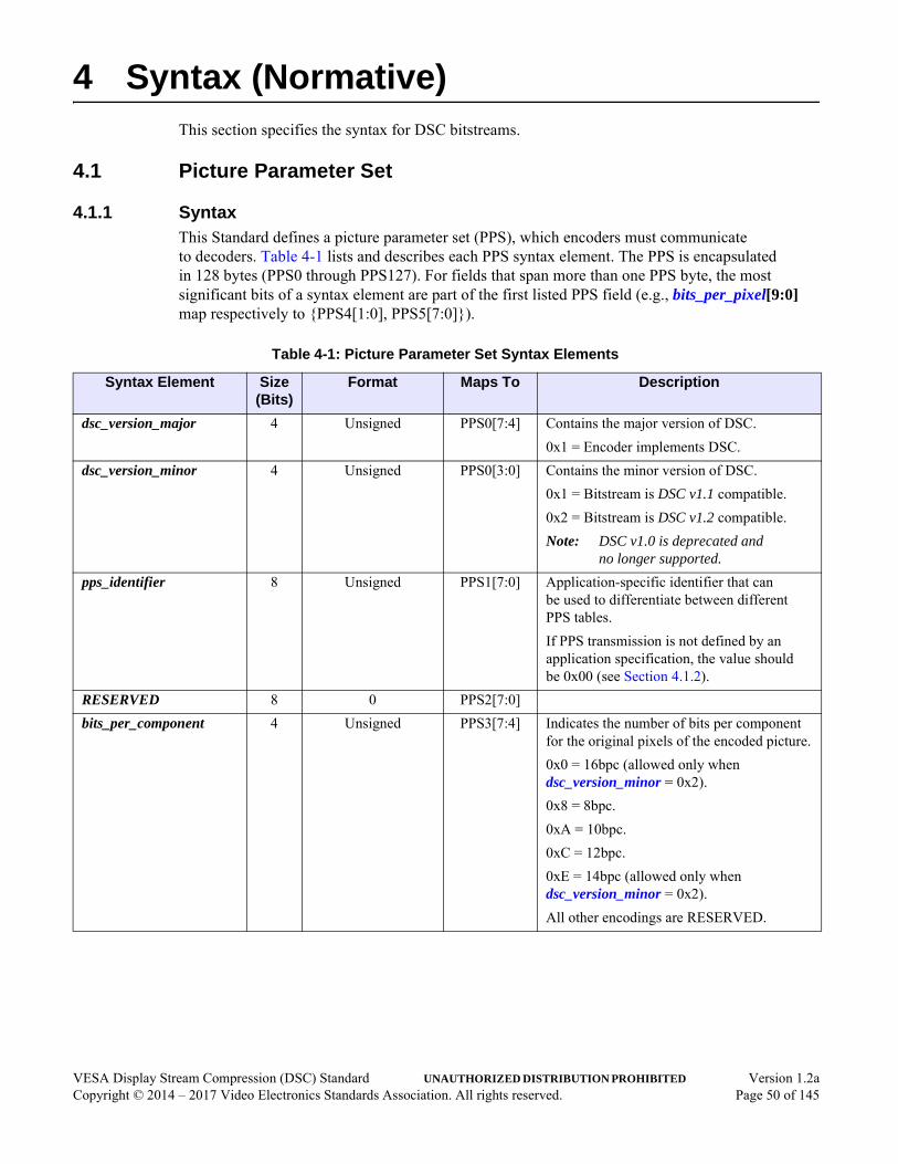
4 Syntax (Normative)This section specifies the syntax for DSC bitstreams.
4.1 Picture Parameter Set
4.1.1 SyntaxThis Standard defines a picture parameter set (PPS), which encoders must communicate to decoders. Table 4-1 lists and describes each PPS syntax element. The PPS is encapsulated in 128 bytes (PPS0 through PPS127). For fields that span more than one PPS byte, the most significant bits of a syntax element are part of the first listed PPS field (e.g., bits_per_pixel[9:0] map respectively to {PPS4[1:0], PPS5[7:0]}).
Table 4-1: Picture Parameter Set Syntax Elements
Syntax Element Size (Bits)
Format Maps To Description
dsc_version_major 4 Unsigned PPS0[7:4] Contains the major version of DSC.
0x1 = Encoder implements DSC.
dsc_version_minor 4 Unsigned PPS0[3:0] Contains the minor version of DSC.
0x1 = Bitstream is DSC v1.1 compatible.
0x2 = Bitstream is DSC v1.2 compatible.
Note: DSC v1.0 is deprecated and no longer supported.
pps_identifier 8 Unsigned PPS1[7:0] Application-specific identifier that can be used to differentiate between different PPS tables.
If PPS transmission is not defined by an application specification, the value should be 0x00 (see Section 4.1.2).
RESERVED 8 0 PPS2[7:0]
bits_per_component 4 Unsigned PPS3[7:4] Indicates the number of bits per component for the original pixels of the encoded picture.
0x0 = 16bpc (allowed only when dsc_version_minor = 0x2).
0x8 = 8bpc.
0xA = 10bpc.
0xC = 12bpc.
0xE = 14bpc (allowed only when dsc_version_minor = 0x2).
All other encodings are RESERVED.
VESA Display Stream Compression (DSC) Standard UNAUTHORIZED DISTRIBUTION PROHIBITED Version 1.2aCopyright © 2014 – 2017 Video Electronics Standards Association. All rights reserved. Page 50 of 145

linebuf_depth 4 Unsigned PPS3[3:0] Contains the line buffer bit depth used to generate the bitstream. If a component’s bit depth (after color space conversion; see Section 6.1) is greater than this value, the line storage rounds the reconstructed values to this number of bits.
0x0 = 16 bits (allowed only when dsc_version_minor = 0x2).
0x8 = 8 bits.
0x9 = 9 bits.
0xA = 10 bits.
0xB = 11 bits.
0xC = 12 bits.
0xD = 13 bits.
0xE = 14 bits (allowed only when dsc_version_minor = 0x2).
0xF = 15 bits (allowed only when dsc_version_minor = 0x2).
All other encodings are RESERVED.
RESERVED 2 0 PPS4[7:6]
block_pred_enable 1 Flag PPS4[5] 0 = BP is not used to code any groups within the picture.
1 = Decoder must select between BP and MMAP, using the method described in Section 6.4.4.1.
convert_rgb 1 Flag PPS4[4] Indicates whether DSC color space conversion is active.
0 = Color space is YCbCr.
1 = Encoder converts RGB to YCoCg-R, and decoder converts YCoCg-R to RGB.
simple_422 1 Flag PPS4[3] Indicates whether a decoder creates a reconstructed 4:2:2 picture by dropping samples using the method described in Annex B.
Value shall be 0 if native_422 or native_420 is set to 1.
0 = Decoder does not drop samples to reconstruct a 4:2:2 picture.
1 = Decoder drops samples to reconstruct a 4:2:2 picture.
Table 4-1: Picture Parameter Set Syntax Elements (Continued)
Syntax Element Size (Bits)
Format Maps To Description
VESA Display Stream Compression (DSC) Standard UNAUTHORIZED DISTRIBUTION PROHIBITED Version 1.2aCopyright © 2014 – 2017 Video Electronics Standards Association. All rights reserved. Page 51 of 145

vbr_enable 1 Flag PPS4[2] 0 = VBR mode is disabled.
1 = VBR mode is enabled, if the mode is supported by the transport and decoder (see Section 3.7.2).
bits_per_pixel 10 Unsigned(four fractional bits)
PPS4[1:0], PPS5[7:0]
Specifies the target bits/pixel (bpp) rate that is used by the encoder, in steps of 1/16 of a bit per pixel. Only values greater than or equal to 6.0 are allowed. If vbr_enable is cleared to 0, this value must be less than or equal to the sustained rate that would apply if MPP is always selected with QP = 0, which is a function of bits_per_component, convert_rgb, and rc_range_parameters[0].If native_422 or native_420 is set to 1, this value shall be programmed to double the target bits per pixel rate.
Note: The maximum supported PPS value is 63.9375.
pic_height 16 Unsigned PPS6[7:0], PPS7[7:0]
Specify the picture size, in units of pixels. pic_height is the number of pixel rows within the raster. pic_width is the number of pixel columns within the raster. Although not required, it is recommended that pic_height and pic_width be close to integer multiples of slice_height and slice_width, respectively.
pic_width 16 Unsigned PPS8[7:0], PPS9[7:0]
slice_height 16 Unsigned PPS10[7:0], PPS11[7:0]
Specify the size for each slice, in units of pixels. All slices that comprise a single picture are required to have an identical size. If the pic_height is not evenly divisible by the slice_height, lines consisting of midpoint-valued samples are added to the bottommost slice(s) so that these slices are the same height as the other slices. If the pic_width is not evenly divisible by the slice_width, the rightmost column of pixels is replicated to pad the rightmost slices to be the same width as the other slices. The transport must allocate transmission time for sending the compressed bits corresponding to any replicated pixels.
slice_height shall be a multiple of 2 if native_420 is set to 1.
slice_width shall be a multiple of 2 if simple_422, native_422, or native_420 is set to 1.
slice_width 16 Unsigned PPS12[7:0], PPS13[7:0]
Table 4-1: Picture Parameter Set Syntax Elements (Continued)
Syntax Element Size (Bits)
Format Maps To Description
VESA Display Stream Compression (DSC) Standard UNAUTHORIZED DISTRIBUTION PROHIBITED Version 1.2aCopyright © 2014 – 2017 Video Electronics Standards Association. All rights reserved. Page 52 of 145
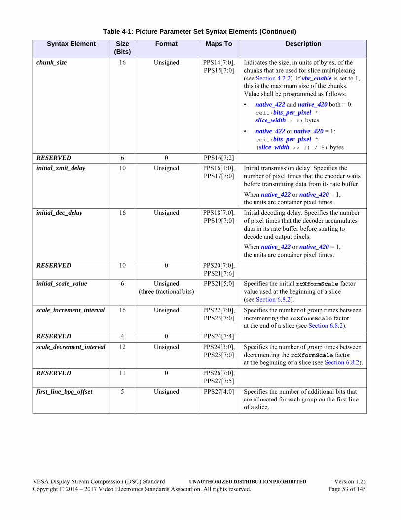
chunk_size 16 Unsigned PPS14[7:0], PPS15[7:0]
Indicates the size, in units of bytes, of the chunks that are used for slice multiplexing (see Section 4.2.2). If vbr_enable is set to 1, this is the maximum size of the chunks. Value shall be programmed as follows:
• native_422 and native_420 both = 0: ceil(bits_per_pixel * slice_width / 8) bytes
• native_422 or native_420 = 1: ceil(bits_per_pixel * (slice_width >> 1) / 8) bytes
RESERVED 6 0 PPS16[7:2]
initial_xmit_delay 10 Unsigned PPS16[1:0], PPS17[7:0]
Initial transmission delay. Specifies the number of pixel times that the encoder waits before transmitting data from its rate buffer.
When native_422 or native_420 = 1, the units are container pixel times.
initial_dec_delay 16 Unsigned PPS18[7:0], PPS19[7:0]
Initial decoding delay. Specifies the number of pixel times that the decoder accumulates data in its rate buffer before starting to decode and output pixels.
When native_422 or native_420 = 1, the units are container pixel times.
RESERVED 10 0 PPS20[7:0], PPS21[7:6]
initial_scale_value 6 Unsigned(three fractional bits)
PPS21[5:0] Specifies the initial rcXformScale factor value used at the beginning of a slice (see Section 6.8.2).
scale_increment_interval 16 Unsigned PPS22[7:0], PPS23[7:0]
Specifies the number of group times between incrementing the rcXformScale factor at the end of a slice (see Section 6.8.2).
RESERVED 4 0 PPS24[7:4]
scale_decrement_interval 12 Unsigned PPS24[3:0], PPS25[7:0]
Specifies the number of group times between decrementing the rcXformScale factor at the beginning of a slice (see Section 6.8.2).
RESERVED 11 0 PPS26[7:0], PPS27[7:5]
first_line_bpg_offset 5 Unsigned PPS27[4:0] Specifies the number of additional bits that are allocated for each group on the first line of a slice.
Table 4-1: Picture Parameter Set Syntax Elements (Continued)
Syntax Element Size (Bits)
Format Maps To Description
VESA Display Stream Compression (DSC) Standard UNAUTHORIZED DISTRIBUTION PROHIBITED Version 1.2aCopyright © 2014 – 2017 Video Electronics Standards Association. All rights reserved. Page 53 of 145

nfl_bpg_offset 16 Unsigned(11 fractional bits)
PPS28[7:0], PPS29[7:0]
Specifies the number of bits (including fractional bits) that are deallocated for each group, for groups after the first line of a slice. If the first line has an additional bit budget, the additional bits that are allocated must come out of the budget for coding the remainder of the slice. Therefore, the value must be programmed to first_line_bpg_offset / (slice_height - 1), then rounded up to 16 fractional bits.
slice_bpg_offset 16 Unsigned(11 fractional bits)
PPS30[7:0], PPS31[7:0]
Specifies the number of bits (including fractional bits) that are deallocated for each group to enforce the slice constraint (i.e., the final buffer model fullness cannot exceed the initial transmission delay times bits per group), while allowing a programmable initial_offset. If the initial rate control (RC) model condition is not completely full, the difference between the initial RC model offset and size (initial_offset and rc_model_size, respectively) must be accounted for. The slice_bpg_offset parameter provides a means to resolve this difference. This parameter also allows the RC algorithm to account for bits that might be lost to SSM at the end of a slice. The value must be programmed to (rc_model_size - initial_offset + numExtraMuxBits) / groupsTotal, then rounded up to 16 fractional bits. numExtraMuxBits and groupsTotal are described in Table E-1.
initial_offset 16 Unsigned PPS32[7:0], PPS33[7:0]
Specifies the initial value for rcXformOffset, which is initial_offset - rc_model_size at the start of a slice (see Section 6.8.2).
final_offset 16 Unsigned PPS34[7:0], PPS35[7:0]
Specifies the maximum end-of-slice value for rcXformOffset, which is final_offset - rc_model_size (see Section 6.8.2). To ensure HRD compliance, the final_offset parameter value must be equal to rc_model_size - initial_xmit_delay * bits_per_pixel + numExtraMuxBits. numExtraMuxBits is described in Table E-1.
RESERVED 3 0 PPS36[7:5]
Table 4-1: Picture Parameter Set Syntax Elements (Continued)
Syntax Element Size (Bits)
Format Maps To Description
VESA Display Stream Compression (DSC) Standard UNAUTHORIZED DISTRIBUTION PROHIBITED Version 1.2aCopyright © 2014 – 2017 Video Electronics Standards Association. All rights reserved. Page 54 of 145

flatness_min_qp 5 Unsigned PPS36[4:0] Specifies the minimum QP at which flatness is signaled and the flatness QP adjustment is made.
RESERVED 3 0 PPS37[7:5]
flatness_max_qp 5 Unsigned PPS37[4:0] Specifies the maximum QP at which flatness is signaled and the flatness QP adjustment is made.
rc_parameter_set 400 SeeTable 4-2
PPS38[7:0] through
PPS87[7:0]
RC algorithm parameters (see Table 4-2 for details).
RESERVED 6 0 PPS88[7:2]
native_420 1 Flag PPS88[1] Value shall be 0 if any of the following conditions exist:
• dsc_version_minor = 1
• simple_422 or native_422 = 1
0 = Native 4:2:0 mode is not used.
1 = Native 4:2:0 mode is used.
native_422 1 Flag PPS88[0] Value shall be 0 if any of the following conditions exist:
• dsc_version_minor = 1
• simple_422 or native_420 = 1
0 = Native 4:2:2 mode is not used.
1 = Native 4:2:2 mode is used.
RESERVED 3 0 PPS89[7:5]
second_line_bpg_offset 5 Unsigned PPS89[4:0] Specifies additional bits/group budget for the second line of a slice in Native 4:2:0 mode (see Section 6.8.2).
Value shall be 0 if either of the following conditions exist:
• dsc_version_minor = 1
• native_420 = 0
Table 4-1: Picture Parameter Set Syntax Elements (Continued)
Syntax Element Size (Bits)
Format Maps To Description
VESA Display Stream Compression (DSC) Standard UNAUTHORIZED DISTRIBUTION PROHIBITED Version 1.2aCopyright © 2014 – 2017 Video Electronics Standards Association. All rights reserved. Page 55 of 145
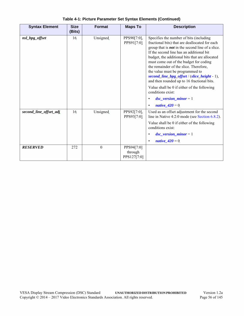
nsl_bpg_offset 16 Unsigned PPS90[7:0], PPS91[7:0]
Specifies the number of bits (including fractional bits) that are deallocated for each group that is not in the second line of a slice. If the second line has an additional bit budget, the additional bits that are allocated must come out of the budget for coding the remainder of the slice. Therefore, the value must be programmed to second_line_bpg_offset / (slice_height - 1), and then rounded up to 16 fractional bits.
Value shall be 0 if either of the following conditions exist:
• dsc_version_minor = 1
• native_420 = 0
second_line_offset_adj 16 Unsigned PPS92[7:0], PPS93[7:0]
Used as an offset adjustment for the second line in Native 4:2:0 mode (see Section 6.8.2).
Value shall be 0 if either of the following conditions exist:
• dsc_version_minor = 1
• native_420 = 0
RESERVED 272 0 PPS94[7:0] through
PPS127[7:0]
Table 4-1: Picture Parameter Set Syntax Elements (Continued)
Syntax Element Size (Bits)
Format Maps To Description
VESA Display Stream Compression (DSC) Standard UNAUTHORIZED DISTRIBUTION PROHIBITED Version 1.2aCopyright © 2014 – 2017 Video Electronics Standards Association. All rights reserved. Page 56 of 145
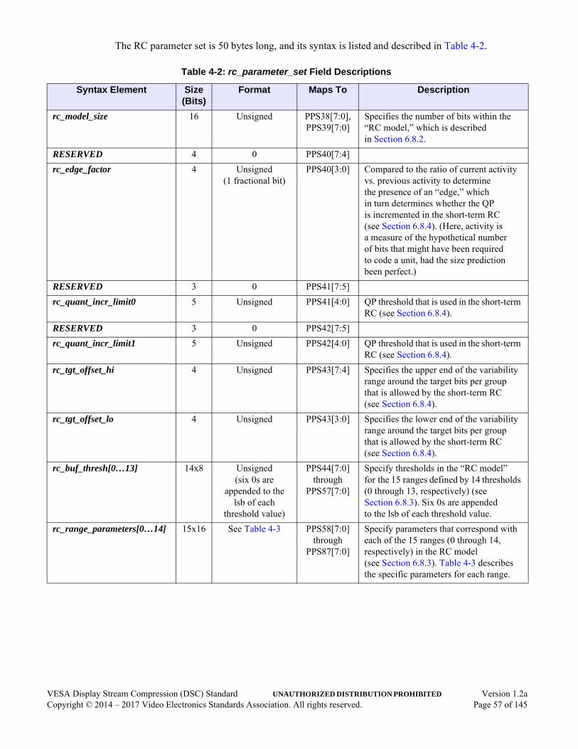
The RC parameter set is 50 bytes long, and its syntax is listed and described in Table 4-2.
Table 4-2: rc_parameter_set Field Descriptions
Syntax Element Size (Bits)
Format Maps To Description
rc_model_size 16 Unsigned PPS38[7:0], PPS39[7:0]
Specifies the number of bits within the “RC model,” which is described in Section 6.8.2.
RESERVED 4 0 PPS40[7:4]
rc_edge_factor 4 Unsigned(1 fractional bit)
PPS40[3:0] Compared to the ratio of current activity vs. previous activity to determine the presence of an “edge,” which in turn determines whether the QP is incremented in the short-term RC (see Section 6.8.4). (Here, activity is a measure of the hypothetical number of bits that might have been required to code a unit, had the size prediction been perfect.)
RESERVED 3 0 PPS41[7:5]
rc_quant_incr_limit0 5 Unsigned PPS41[4:0] QP threshold that is used in the short-term RC (see Section 6.8.4).
RESERVED 3 0 PPS42[7:5]
rc_quant_incr_limit1 5 Unsigned PPS42[4:0] QP threshold that is used in the short-term RC (see Section 6.8.4).
rc_tgt_offset_hi 4 Unsigned PPS43[7:4] Specifies the upper end of the variability range around the target bits per group that is allowed by the short-term RC (see Section 6.8.4).
rc_tgt_offset_lo 4 Unsigned PPS43[3:0] Specifies the lower end of the variability range around the target bits per group that is allowed by the short-term RC (see Section 6.8.4).
rc_buf_thresh[0…13] 14x8 Unsigned(six 0s are
appended to the lsb of each
threshold value)
PPS44[7:0] through
PPS57[7:0]
Specify thresholds in the “RC model” for the 15 ranges defined by 14 thresholds (0 through 13, respectively) (see Section 6.8.3). Six 0s are appended to the lsb of each threshold value.
rc_range_parameters[0…14] 15x16 See Table 4-3 PPS58[7:0] through
PPS87[7:0]
Specify parameters that correspond with each of the 15 ranges (0 through 14, respectively) in the RC model (see Section 6.8.3). Table 4-3 describes the specific parameters for each range.
VESA Display Stream Compression (DSC) Standard UNAUTHORIZED DISTRIBUTION PROHIBITED Version 1.2aCopyright © 2014 – 2017 Video Electronics Standards Association. All rights reserved. Page 57 of 145
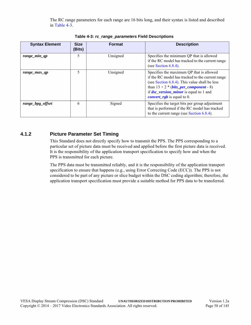
The RC range parameters for each range are 16 bits long, and their syntax is listed and described in Table 4-3.
4.1.2 Picture Parameter Set TimingThis Standard does not directly specify how to transmit the PPS. The PPS corresponding to a particular set of picture data must be received and applied before the first picture data is received. It is the responsibility of the application transport specification to specify how and when the PPS is transmitted for each picture.
The PPS data must be transmitted reliably, and it is the responsibility of the application transport specification to ensure that happens (e.g., using Error Correcting Code (ECC)). The PPS is not considered to be part of any picture or slice budget within the DSC coding algorithm; therefore, the application transport specification must provide a suitable method for PPS data to be transferred.
Table 4-3: rc_range_parameters Field Descriptions
Syntax Element Size (Bits)
Format Description
range_min_qp 5 Unsigned Specifies the minimum QP that is allowed if the RC model has tracked to the current range (see Section 6.8.4).
range_max_qp 5 Unsigned Specifies the maximum QP that is allowed if the RC model has tracked to the current range (see Section 6.8.4). This value shall be less than 13 + 2 * (bits_per_component - 8) if dsc_version_minor is equal to 1 and convert_rgb is equal to 0.
range_bpg_offset 6 Signed Specifies the target bits per group adjustment that is performed if the RC model has tracked to the current range (see Section 6.8.4).
VESA Display Stream Compression (DSC) Standard UNAUTHORIZED DISTRIBUTION PROHIBITED Version 1.2aCopyright © 2014 – 2017 Video Electronics Standards Association. All rights reserved. Page 58 of 145
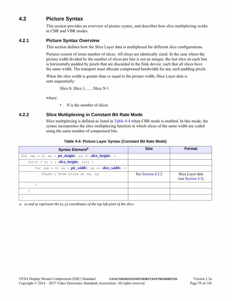
4.2 Picture SyntaxThis section provides an overview of picture syntax, and describes how slice multiplexing works in CBR and VBR modes.
4.2.1 Picture Syntax OverviewThis section defines how the Slice Layer data is multiplexed for different slice configurations.
Pictures consist of some number of slices. All slices are identically sized. In the case where the picture width divided by the number of slices per line is not an integer, the last slice on each line is horizontally padded by pixels that are discarded in the Sink device, such that all slices have the same width. The transport must allocate compressed bandwidth for any such padding pixels.
When the slice width is greater than or equal to the picture width, Slice Layer data is sent sequentially:
Slice 0, Slice 1, …, Slice N-1
where:
• N is the number of slices
4.2.2 Slice Multiplexing in Constant Bit Rate ModeSlice multiplexing is defined as listed in Table 4-4 when CBR mode is enabled. In this mode, the syntax incorporates the slice multiplexing function in which slices of the same width are coded using the same number of compressed bits.
Table 4-4: Picture Layer Syntax (Constant Bit Rate Mode)
Syntax Elementa
a. sx and sy represent the (x, y) coordinates of the top left pixel of the slice.
Size Format
for (sy = 0; sy < pic_height; sy += slice_height) {for(i = 0; i < slice_height; ++i) {
for (sx = 0; sx < pic_width; sx += slice_width) {Chunk i from slice at sx, sy See Section 4.2.2 Slice Layer data
(see Section 4.3)
}
}
}
VESA Display Stream Compression (DSC) Standard UNAUTHORIZED DISTRIBUTION PROHIBITED Version 1.2aCopyright © 2014 – 2017 Video Electronics Standards Association. All rights reserved. Page 59 of 145
The slice data for all slices on the same line is multiplexed into fixed-length chunks. The length of each chunk is calculated as follows:
• native_422 and native_420 are both cleared to 0: ceil(bits_per_pixel * slice_width / 8) bytes
• native_422 or native_420 is set to 1: ceil(bits_per_pixel * (slice_width >> 1) / 8) bytes
The ceil() function is required because the bits_per_pixel value might be fractional and all bits are carried by the equally sized chunks. The specification of chunk size, in units of bytes, enables transport schemes to use byte-aligned chunks of data. For example, in a case where the picture is split into two equally sized slices on each line, the multiplexed bitstream would contain:
Slice 0 chunk / Slice 1 chunk / Slice 0 chunk / Slice 1 chunk …
The final chunks of each slice are stuffed with “0” padding bits, if needed, due to the ceil() function. For the other previous chunks within the slice, the RC algorithm adjusts for the extra bits created by the ceil() function so that no “0” padding bits are required for the previous chunks.
4.2.3 Slice Multiplexing in Variable Bit Rate ModeWhen VBR mode is enabled, the number of bits coding each slice (and chunk) can vary. Hence, there is some added complexity. Each chunk has a variable size that must be communicated (see Table 4-5), either in a packet header or some other defined mechanism within the Transport Layer, which is outside the scope of this Standard.
VESA Display Stream Compression (DSC) Standard UNAUTHORIZED DISTRIBUTION PROHIBITED Version 1.2aCopyright © 2014 – 2017 Video Electronics Standards Association. All rights reserved. Page 60 of 145
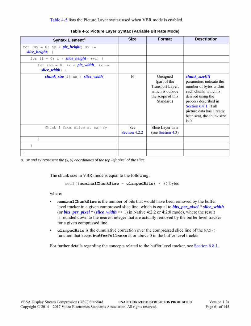
Table 4-5 lists the Picture Layer syntax used when VBR mode is enabled.
The chunk size in VBR mode is equal to the following:
ceil((nominalChunkSize - clampedBits) / 8) bytes
where:
• nominalChunkSize is the number of bits that would have been removed by the buffer level tracker in a given compressed slice line, which is equal to bits_per_pixel * slice_width (or bits_per_pixel * (slice_width >> 1) in Native 4:2:2 or 4:2:0 mode), where the result is rounded down to the nearest integer that are actually removed by the buffer level tracker for a given compressed line
• clampedBits is the cumulative correction over the compressed slice line of the MAX() function that keeps bufferFullness at or above 0 in the buffer level tracker
For further details regarding the concepts related to the buffer level tracker, see Section 6.8.1.
Table 4-5: Picture Layer Syntax (Variable Bit Rate Mode)
Syntax Elementa
a. sx and sy represent the (x, y) coordinates of the top left pixel of the slice.
Size Format Description
for (sy = 0; sy < pic_height; sy += slice_height) {for (i = 0; i < slice_height; ++i) {
for (sx = 0; sx < pic_width; sx += slice_width) {
chunk_size[i][sx / slice_width] 16 Unsigned(part of the
Transport Layer, which is outside the scope of this
Standard)
chunk_size[][] parameters indicate the number of bytes within each chunk, which is derived using the process described in Section 6.8.1. If all picture data has already been sent, the chunk size is 0.
Chunk i from slice at sx, sy See Section 4.2.2
Slice Layer data(see Section 4.3)
}
}
}
VESA Display Stream Compression (DSC) Standard UNAUTHORIZED DISTRIBUTION PROHIBITED Version 1.2aCopyright © 2014 – 2017 Video Electronics Standards Association. All rights reserved. Page 61 of 145

4.3 SliceEach slice comprises a number of groups. If native_422 and native_420 are both cleared to 0, each group consists of three pixels, except where the last group of a line contains fewer pixels to fit the slice width. Each 4:4:4 pixel has three components:
• Y, Co, and Cg, or
• Y, Cr, and Cb
When native_422 or native_420 is set to 1, the group size is six pixels, and each pair of pixels is described by two Y samples and one or two chroma samples. In this case, the codec reorders the samples into a half-width 4:4:4:4 or 4:4:4 container in which even- and odd-position luma samples are treated as separate components. This container is then divided into half-width slices and coded using the standard 4:4:4 toolset and a group size of three.
Three samples of one component from the same group are coded using a single DSU-VLC unit (see Section 6.6.1) or an escape code along with fixed-length codes for ICH-mode. When native_422 is cleared to 0, a predictive-coded group has three units, one per component. When native_422 is set to 1, a predictive-coded group has four units, two for luma and one for each chroma component. In the case of ICH coding of a group, the first unit uses a modified DSU-VLC code and the other units contain fixed-length codes corresponding to history index codes. The bits corresponding to a single component’s worth of data for a single group is also referred to as a “syntax element,” and the seSize_Y[], seSize_Co[], seSize_Cg[], and seSize_Y2[] syntax element sizes are used in the sspFullness_Y, sspFullness_Co, sspFullness_Cg, and sspFullness_Y2 definitions, respectively, as described in Section 4.4.
The bits representing each slice are the result of the SSM process. Therefore, the group is a logical construct that does not directly represent a sequence of bits within the bitstream.
VESA Display Stream Compression (DSC) Standard UNAUTHORIZED DISTRIBUTION PROHIBITED Version 1.2aCopyright © 2014 – 2017 Video Electronics Standards Association. All rights reserved. Page 62 of 145

4.4 Substream MultiplexingEach slice consists of three or four parallel substreams in which each substream corresponds to a component. The substreams are multiplexed together, as follows:
• Native 4:2:2 mode has four substreams:
• One substream for even-position luma samples
• One substream for odd-position luma samples
• Two substreams for chroma samples (Cb and Cr)
• Native 4:2:0 mode has three substreams:
• Two substreams for luma samples (one of which maps to the Co substream)
• One substream for chroma samples (which maps to the Cg substream)
The muxWordSize is determined by the bits_per_component value:
• When bits_per_component is 12, 14, or 16bpc, muxWordSize shall be equal to 64 bits
• When bits_per_component is 8 or 10bpc, muxWordSize shall be equal to 48 bits
For each group time, either 0, 1, 2, 3, or 4 mux words of size muxWordSize are inserted into the bitstream, depending on the sspFullness_Y, sspFullness_Co, sspFullness_Cg, or sspFullness_Y2 state. The sspFullness_Y value increases by muxWordSize when a Y mux word is inserted, which occurs when sspFullness_Y falls below the maximum syntax element size for Y. The sspFullness_Y value decreases by the size of the syntax element (seSize_Y[]) that is parsed within each substream. The same algorithms apply for sspFullness_Co, sspFullness_Cg, and sspFullness_Y2.
Table 4-6 lists the Slice Layer syntax. Table 4-7 describes each Slice Layer syntax field.
VESA Display Stream Compression (DSC) Standard UNAUTHORIZED DISTRIBUTION PROHIBITED Version 1.2aCopyright © 2014 – 2017 Video Electronics Standards Association. All rights reserved. Page 63 of 145

Table 4-6: Slice Layer Syntax when native_422 = 0
Fielda
a. groupsTotal is described in Table E-1.
Size Format
for (grpNum = 0; grpNum < groupsTotal; ++grpNum) {
if(sspFullness_Y < maxSeSize_Y) {
mux_word_from_Y_substream muxWordSize Substream Layer data(see Section 4.5)
sspFullness_Y += muxWordSize;
}
if(sspFullness_Co < maxSeSize_Co) {
mux_word_from_Co_substream muxWordSize Substream Layer data(see Section 4.5)
sspFullness_Co += muxWordSize;
}
if(sspFullness_Cg < maxSeSize_Cg) {
mux_word_from_Cg_substream muxWordSize Substream Layer data(see Section 4.5)
sspFullness_Cg += muxWordSize;
}
if(native_422 && sspFullness_Y2 < maxSeSize_Y2) {
mux_word_from_Y2_substream muxWordSize Substream Layer data(see Section 4.5)
sspFullness_Y2 += muxWordSize;
}
sspFullness_Y -= seSize_Y[grpNum];
sspFullness_Co -= seSize_Co[grpNum];
sspFullness_Cg -= seSize_Cg[grpNum];
sspFullness_Y2 -= seSize_Y2[grpNum];
}
Table 4-7: Slice Layer Syntax Field Descriptions
Field Description
mux_word_from_Y_substream Chunk of data from the Y substream (see Table 4-8) that is muxWordSize bits long.
mux_word_from_Co_substream Chunk of data from the Co substream (see Table 4-14) that is muxWordSize bits long.
mux_word_from_Cg_substream Chunk of data from the Cg substream (see Table 4-17) that is muxWordSize bits long.
mux_word_from_Y2_substream Chunk of data from the Y2 substream (see Table 4-11) that is muxWordSize bits long.
VESA Display Stream Compression (DSC) Standard UNAUTHORIZED DISTRIBUTION PROHIBITED Version 1.2aCopyright © 2014 – 2017 Video Electronics Standards Association. All rights reserved. Page 64 of 145
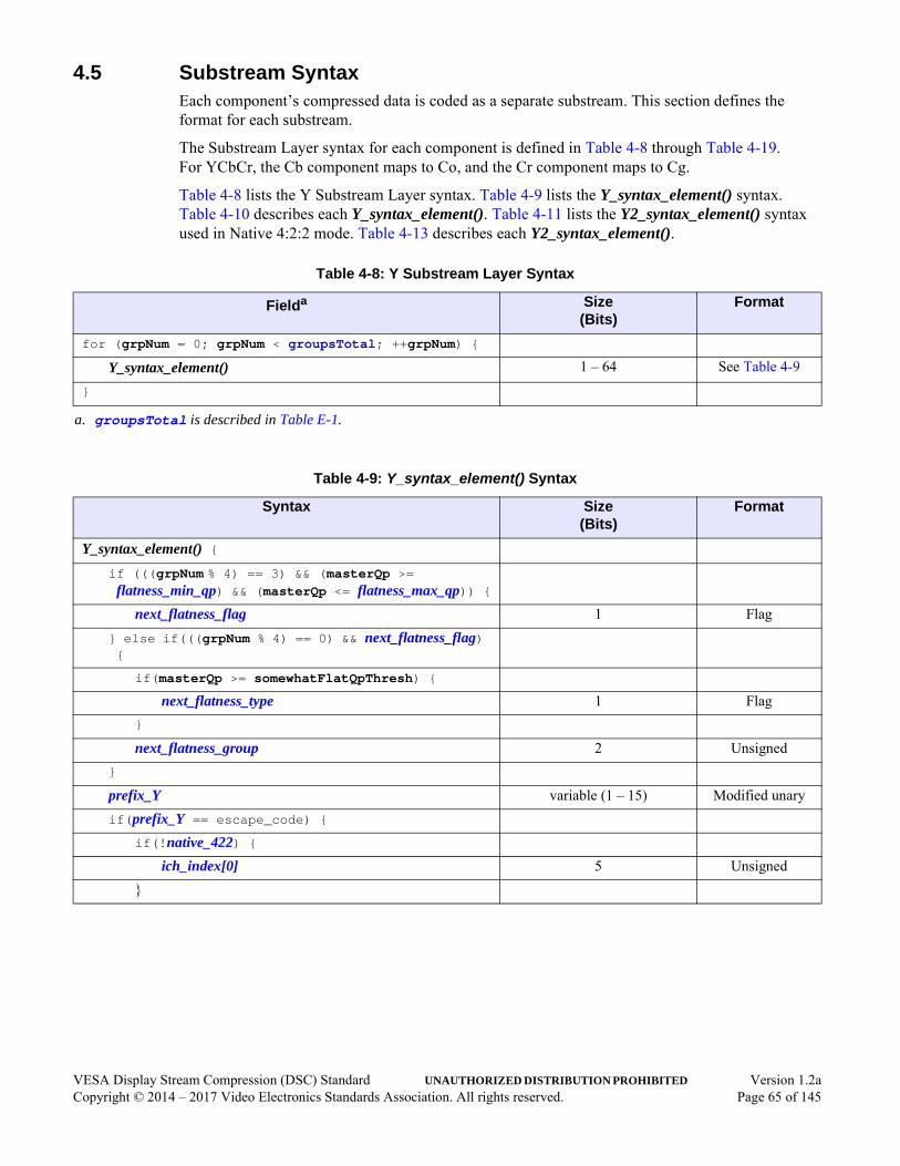
4.5 Substream SyntaxEach component’s compressed data is coded as a separate substream. This section defines the format for each substream.
The Substream Layer syntax for each component is defined in Table 4-8 through Table 4-19. For YCbCr, the Cb component maps to Co, and the Cr component maps to Cg.
Table 4-8 lists the Y Substream Layer syntax. Table 4-9 lists the Y_syntax_element() syntax. Table 4-10 describes each Y_syntax_element(). Table 4-11 lists the Y2_syntax_element() syntax used in Native 4:2:2 mode. Table 4-13 describes each Y2_syntax_element().
Table 4-8: Y Substream Layer Syntax
Fielda
a. groupsTotal is described in Table E-1.
Size(Bits)
Format
for (grpNum = 0; grpNum < groupsTotal; ++grpNum) {
Y_syntax_element() 1 – 64 See Table 4-9
}
Table 4-9: Y_syntax_element() Syntax
Syntax Size(Bits)
Format
Y_syntax_element() {if (((grpNum % 4) == 3) && (masterQp >=
flatness_min_qp) && (masterQp <= flatness_max_qp)) {next_flatness_flag 1 Flag
} else if(((grpNum % 4) == 0) && next_flatness_flag) {
if(masterQp >= somewhatFlatQpThresh) {
next_flatness_type 1 Flag
}
next_flatness_group 2 Unsigned
}
prefix_Y variable (1 – 15) Modified unary
if(prefix_Y == escape_code) {if(!native_422) {
ich_index[0] 5 Unsigned
}
VESA Display Stream Compression (DSC) Standard UNAUTHORIZED DISTRIBUTION PROHIBITED Version 1.2aCopyright © 2014 – 2017 Video Electronics Standards Association. All rights reserved. Page 65 of 145

} else {
quantized_residual_Y[0] MAX(residualSizeY, predictedSizeY)
Two’s complement
quantized_residual_Y[1] MAX(residualSizeY, predictedSizeY)
Two’s complement
quantized_residual_Y[2] MAX(residualSizeY, predictedSizeY)
Two’s complement
}
}
Table 4-9: Y_syntax_element() Syntax (Continued)
Syntax Size(Bits)
Format
VESA Display Stream Compression (DSC) Standard UNAUTHORIZED DISTRIBUTION PROHIBITED Version 1.2aCopyright © 2014 – 2017 Video Electronics Standards Association. All rights reserved. Page 66 of 145

Table 4-10: Y_syntax_element() Descriptions
Syntax Element Description
next_flatness_flag Parameter. Maps directly to the flatnessFlag that applies to the supergroup that starts at the second group to the right. If flatnessFlag is set to 1 for a particular supergroup, one of the four consecutive groups is signaled as being flat and a QP adjustment might be applied (see Section 6.8.5.2).
next_flatness_group Parameter. Maps directly to the flatnessGroup that applies to the supergroup that starts with the first group to the right. The flatnessGroup indicates to which of the four consecutive groups in that supergroup the flatness QP adjustment applies (see Section 6.8.5.2).
next_flatness_type Parameter. Maps directly to the flatnessType that applies to the supergroup that starts with the group to the right (see Section 6.8.5.2). The two possible values are:
0 = “Somewhat flat.”
1 = “Very flat.”
prefix_Y Field. Indicates the size delta, which is the number of additional bits beyond the predicted size needed to hold each residual (i.e., MAX(0, residualSizeY - predictedSizeY), where residualSizeY is the minimum number of bits required to represent any of the three residuals, and predictedSizeY is the predicted size (see Section 6.6.1)). Indicating the size as bits_per_component - qLevelY + 1 is an escape code to use ICH-mode. Once in ICH-mode, the escape code becomes a size indication of predictedSizeY (i.e., prefix_Y = 1), and switching back to P-mode requires coding a size delta of 1 + MAX(0, residualSizeY - predictedSizeY).
The coding used is a modified unary code. In general, there are some number of “0” bits, followed by a “1” bit (e.g., 001b indicates a value of 2). However, the final “1” bit is omitted if the bit can be inferred (i.e., the prefix_Y unary code contains (bits_per_component - qLevelY + 1) “0” bits).
If bits_per_component == 16 and masterQp == 0, the maximum length of this field is 13, ICH is disallowed, and the prefix is not adjusted if the previous group was coded in ICH-mode. If all 13 bits are “0” bits, midpoint prediction is used for the residuals, which are each 16 bits long regardless of the size prediction.
ich_index[0] ICH index corresponding to the first (i.e., leftmost) pixel within the group.
quantized_residual_Y[0] Two’s complement representation of the Y quantized residual corresponding to the first (i.e., leftmost) pixel within the group.
quantized_residual_Y[1] Two’s complement representation of the Y quantized residual corresponding to the second pixel within the group.
quantized_residual_Y[2] Two’s complement representation of the Y quantized residual corresponding to the third pixel within the group.
Table 4-11: Y2 Substream Layer Syntax (Native 4:2:2 Mode Only)
Fielda
a. groupsTotal is described in Table E-1.
Size(Bits)
Format
for (grpNum = 0; grpNum < groupsTotal; ++grpNum) {
Y2_syntax_element() 1 – 64 See Table 4-12
}
VESA Display Stream Compression (DSC) Standard UNAUTHORIZED DISTRIBUTION PROHIBITED Version 1.2aCopyright © 2014 – 2017 Video Electronics Standards Association. All rights reserved. Page 67 of 145

Table 4-12: Y2_syntax_element() Syntax (Native 4:2:2 Mode Only)
Syntax Size(Bits)
Format
Y2_syntax_element() {if(prefix_Y == escape_code) {
ich_index[0] 5 Unsigned
} else {
prefix_Y2 variable (1 – 16) Modified unary
quantized_residual_Y2[0] MAX(residualSizeY2, predictedSizeY2)
Two’s complement
quantized_residual_Y2[1] MAX(residualSizeY2, predictedSizeY2)
Two’s complement
quantized_residual_Y2[2] MAX(residualSizeY2, predictedSizeY2)
Two’s complement
}
}
Table 4-13: Y2_syntax_element() Descriptions
Syntax Element Description
prefix_Y2 Field. Indicates the size delta, which is the number of additional bits beyond the predicted size needed to hold each residual (i.e., MAX(0, residualSizeY2 - predictedSizeY2), where residualSizeY2 is the minimum number of bits required to represent any of the three residuals, and predictedSizeY2 is the predicted size (see Section 6.6.1)). No adjustments to prefix_Y2 are made based on the previous group’s mode.
The coding used is a modified unary code. In general, there are some number of “0” bits, followed by a “1” bit (e.g., 001b indicates a value of 2). However, the final “1” bit is omitted if the bit can be inferred (i.e., the prefix_Y2 unary code contains (bits_per_component - qLevelY) “0” bits).
ich_index[0] ICH index corresponding to the 1st (i.e., leftmost) pixel within the group.
quantized_residual_Y2[0] Two’s complement representation of the first odd-position Y quantized residual within the group.
quantized_residual_Y2[1] Two’s complement representation of the second odd-position Y quantized residual within the group.
quantized_residual_Y2[2] Two’s complement representation of the third odd-position Y quantized residual within the group.
VESA Display Stream Compression (DSC) Standard UNAUTHORIZED DISTRIBUTION PROHIBITED Version 1.2aCopyright © 2014 – 2017 Video Electronics Standards Association. All rights reserved. Page 68 of 145

Table 4-14 lists the Co Substream Layer syntax. Table 4-15 lists the Co_syntax_element() syntax. Table 4-16 describes each Co_syntax_element().
Table 4-14: Co Substream Layer Syntax
Fielda
a. groupsTotal is described in Table E-1.
Size(Bits)
Format
for (grpNum = 0; grpNum < groupsTotal; ++grpNum) {
Co_syntax_element() 1 – 64 See Table 4-15
}
Table 4-15: Co_syntax_element() Syntax
Syntax Size(Bits)
Coding
Co_syntax_element() {if (prefix_Y == escape_code) {
ich_index[1] 5 Unsigned
} else {
prefix_Co variable (1 – 16) Modified unary
quantized_residual_Co[0] MAX(residualSizeCo, predictedSizeCo)
Two’s complement
quantized_residual_Co[1] MAX(residualSizeCo, predictedSizeCo)
Two’s complement
quantized_residual_Co[2] MAX(residualSizeCo, predictedSizeCo)
Two’s complement
}
}
VESA Display Stream Compression (DSC) Standard UNAUTHORIZED DISTRIBUTION PROHIBITED Version 1.2aCopyright © 2014 – 2017 Video Electronics Standards Association. All rights reserved. Page 69 of 145

Table 4-16: Co_syntax_element() Descriptions
Syntax Element Description
ich_index[1] ICH index corresponding to the second (middle) pixel within the group.
prefix_Co Field. Indicates the size delta, which is number of additional bits beyond the predicted size needed to hold each residual (i.e., MAX(0, residualSizeCo - predictedSizeCo), where residualSizeCo is the minimum number of bits required to represent any of the three residuals, and predictedSizeCo is the predicted size (see Section 6.6.1)).
The coding used is a modified unary code. In general, there are some number of “0” bits, followed by a “1” bit (e.g., 001b indicates a value of 2). However, the final “1” bit is omitted if the bit can be inferred (i.e., the prefix_Co unary code contains (cpntBitDepth_C - qLevelC) “0” bits, where cpntBitDepth_C is the chroma bit depth).
quantized_residual_Co[0] Two’s complement representation of the Co/Cb quantized residual corresponding to the leftmost sample within the group.
quantized_residual_Co[1] Two’s complement representation of the Co/Cb quantized residual corresponding to the middle sample within the group.
quantized_residual_Co[2] Two’s complement representation of the Co/Cb quantized residual corresponding to the rightmost sample within the group.
VESA Display Stream Compression (DSC) Standard UNAUTHORIZED DISTRIBUTION PROHIBITED Version 1.2aCopyright © 2014 – 2017 Video Electronics Standards Association. All rights reserved. Page 70 of 145
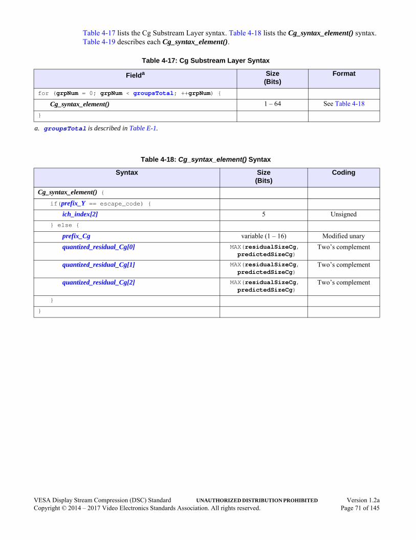
Table 4-17 lists the Cg Substream Layer syntax. Table 4-18 lists the Cg_syntax_element() syntax. Table 4-19 describes each Cg_syntax_element().
Table 4-17: Cg Substream Layer Syntax
Fielda
a. groupsTotal is described in Table E-1.
Size(Bits)
Format
for (grpNum = 0; grpNum < groupsTotal; ++grpNum) {
Cg_syntax_element() 1 – 64 See Table 4-18
}
Table 4-18: Cg_syntax_element() Syntax
Syntax Size(Bits)
Coding
Cg_syntax_element() {if(prefix_Y == escape_code) {
ich_index[2] 5 Unsigned
} else {
prefix_Cg variable (1 – 16) Modified unary
quantized_residual_Cg[0] MAX(residualSizeCg, predictedSizeCg)
Two’s complement
quantized_residual_Cg[1] MAX(residualSizeCg, predictedSizeCg)
Two’s complement
quantized_residual_Cg[2] MAX(residualSizeCg, predictedSizeCg)
Two’s complement
}
}
VESA Display Stream Compression (DSC) Standard UNAUTHORIZED DISTRIBUTION PROHIBITED Version 1.2aCopyright © 2014 – 2017 Video Electronics Standards Association. All rights reserved. Page 71 of 145

Table 4-19: Cg_syntax_element() Descriptions
Syntax Element Description
ich_index[2] ICH index corresponding to the rightmost pixel within the group.
prefix_Cg Field. Indicates the size delta, which is number of additional bits beyond the predicted size needed to hold each residual (i.e., MAX(0, residualSizeCg - predictedSizeCg), where residualSizeCg is the minimum number of bits required to represent any of the three residuals, and predictedSizeCg is the predicted size (see Section 6.6.1)).
The coding used is a modified unary code. In general, there are some number of “0” bits, followed by a “1” bit (e.g., 001b indicates a value of 2). However, the final “1” bit is omitted if the bit can be inferred (i.e., the prefix_Cg unary code contains (cpntBitDepth_C - qLevelCg) “0” bits, where cpntBitDepth_C is the chroma bit depth).
quantized_residual_Cg[0] Two’s complement representation of the Cg/Cr quantized residual corresponding to the leftmost chroma sample within the group.
quantized_residual_Cg[1] Two’s complement representation of the Cg/Cr quantized residual corresponding to the middle chroma sample within the group.
quantized_residual_Cg[2] Two’s complement representation of the Cg/Cr quantized residual corresponding to the rightmost chroma sample within the group.
VESA Display Stream Compression (DSC) Standard UNAUTHORIZED DISTRIBUTION PROHIBITED Version 1.2aCopyright © 2014 – 2017 Video Electronics Standards Association. All rights reserved. Page 72 of 145

VESA Display Stream Compression (DSC) Standard UNAUTHORIZED DISTRIBUTION PROHIBITED Version 1.2aCopyright © 2014 – 2017 Video Electronics Standards Association. All rights reserved. Page 73 of 145
5 Capability Parameter Set (Informative)It can be helpful for the transport in an application specification to define a way for the decoder to communicate the capability parameters listed in Table 5-1 to the encoder. This list is not intended to be exhaustive.
Table 5-1: Recommended Capability Parameter Set
Name Format Description
Block_prediction_allowed Flag 0 = Decoder does not support block prediction.
1 = Decoder supports block prediction.
Display_bpc 4 bits Native bits per component of the display.
Line_buf_bit_depth 4 bits Indicates the number of bits of precision within the decoder line buffer.
Native_420_support Flag 0 = Decoder does not support Native 4:2:0 mode.
1 = Decoder supports Native 4:2:0 mode.
Native_422_support Flag 0 = Decoder does not support Native 4:2:2 mode.
1 = Decoder supports Native 4:2:2 mode.
Picture_height 16 bits Indicates the number of rows that comprise the picture height.
Picture_width 16 bits Indicates the number of columns that comprise the picture width.
Rate_buffer_size 16 bits Indicates the number of bits that can be supported in the decoder rate buffer model.
Slice_height 16 bits Indicates the number of pixel rows that comprise the slice height.
Slice_width 16 bits Indicates the number of pixel columns that comprise the slice width
Supported_dsc_version 4 bits major/4 bits minor
Indicates the major/minor DSC version supported by the decoder.
Vbr_allowed Flag 0 = Does not support VBR.
1 = Supports VBR, where “0” padding bits are not sent.

6 Encoding Process (Normative)This section describes the processing required for DSC-compatible encoders. If there are discrepancies between this Standard and the C model, the C model implementation takes precedence. References to the C model are provided below the section headers, as appropriate.
6.1 Color Space Conversionmodel note: MN_ENC_CSC in dsc_util.c
DSC is specified in terms of components that are labeled Y, Co, and Cg.
If the convert_rgb flag is cleared to 0 in the current PPS, the encoder shall accept YCbCr input. The Cb component is mapped to the Co component label. The Cr component is mapped to the Cg component label. In this case, the Cb and Cr component bit depth is equal to the Y component, whose bit depth is specified using the bits_per_component parameter in the current PPS.
If the convert_rgb flag is set to 1 in the current PPS, the encoder shall perform a color space conversion (CSC) from RGB to YCoCg-R. The CSC is specified as follows:
cscCo = R - B
t = B + (cscCo >> 1)
cscCg = G - t
Y = t + (cscCg >> 1)
where:
• t is a temporary storage value
• Y is the Y component sample value
When bits_per_component is 8, 10, or 12bpc, or 14bpc, cscCo and cscCg have one additional bit of dynamic range compared with Y, so that the Co and Cg component bit depth (cpntBitDepth_C) is one greater than the luma bit depth, which is specified by bits_per_component. The final Co and Cg values are centered around the midpoint:
Co = cscCo + (1 << bits_per_component)Cg = cscCg + (1 << bits_per_component)
When bits_per_component is 16bpc (DSC v1.2 and higher), the encoder shall round the chroma’s lsb. Co and Cg component bit depth (cpntBitDepth_C) is then the same as the luma bit depth (16 bits). The final Co and Cg values are centered around the midpoint:
Co = MIN (0xFFFF, ((cscCo + 1) >> 1) + 0x8000
Cg = MIN (0xFFFF, ((cscCg + 1) >> 1) + 0x8000
VESA Display Stream Compression (DSC) Standard UNAUTHORIZED DISTRIBUTION PROHIBITED Version 1.2aCopyright © 2014 – 2017 Video Electronics Standards Association. All rights reserved. Page 74 of 145
When native_422 is enabled:
• Even-position luma samples are treated as the first component
• Cb samples are treated as the second component
• Cr samples are treated as the third component
• Odd-position luma samples are treated as the fourth component
When native_420 is enabled:
• Even-position luma samples are treated as the first component
• Odd-position luma samples are treated as the second component
• Chroma samples are treated as the third component (Cb samples are encoded on even-position lines and Cr samples are encoded on odd-position lines)
6.2 Slice PaddingIf a slice extends beyond the right edge of a picture, the rightmost pixel within each line of the picture is replicated to pad the slice to the correct horizontal size. If a slice extends beyond the bottom edge of a picture, the encoder pads the slice to the correct vertical size, using a midpoint sample value for each component (e.g., for 8bpc, Y = 0x80, Co = 0x100, and Cg = 0x100).
6.3 Line Storagemodel note: MN_LINE_STORAGE in dsc_codec.c
DSC requires storage of the previous line’s reconstructed pixel values for MMAP prediction and ICH. Typically, a decoder line buffer would have sufficient storage to contain the full-range reconstructed samples. However, some decoders might use a smaller bit depth to minimize implementation costs, at a slight impact to picture quality.
If a smaller bit depth is used, the decoder must communicate this to the encoder using a mechanism that is not defined within this Standard (see Section 5). The encoder shall program linebuf_depth according to what the decoder implementation supports. The following method for bit-reducing samples shall be used:
shiftAmount = MAX(0, cpntBitDepth - linebuf_depth);round = (shiftAmount > 0) ? (1 << (shiftAmount - 1)) : 0;
storedSample = MIN((sample + round) >> shiftAmount, (1 << linebuf_depth) - 1);
readSample = storedSample << shiftAmount;
where:
• cpntBitDepth is the current component’s bit depth
• storedSample is the sample value that is written to the decoder line buffer
• readSample is the value that is read back from the decoder line buffer
VESA Display Stream Compression (DSC) Standard UNAUTHORIZED DISTRIBUTION PROHIBITED Version 1.2aCopyright © 2014 – 2017 Video Electronics Standards Association. All rights reserved. Page 75 of 145
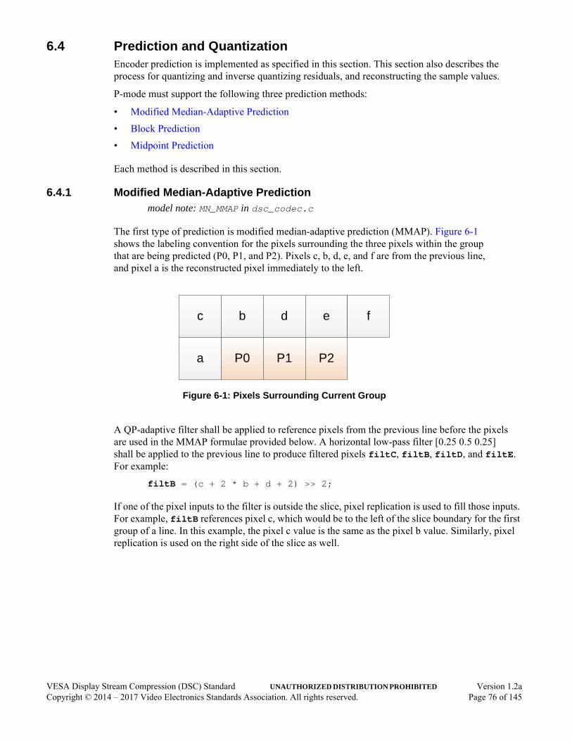
6.4 Prediction and QuantizationEncoder prediction is implemented as specified in this section. This section also describes the process for quantizing and inverse quantizing residuals, and reconstructing the sample values.
P-mode must support the following three prediction methods:
• Modified Median-Adaptive Prediction
• Block Prediction
• Midpoint Prediction
Each method is described in this section.
6.4.1 Modified Median-Adaptive Predictionmodel note: MN_MMAP in dsc_codec.c
The first type of prediction is modified median-adaptive prediction (MMAP). Figure 6-1 shows the labeling convention for the pixels surrounding the three pixels within the group that are being predicted (P0, P1, and P2). Pixels c, b, d, e, and f are from the previous line, and pixel a is the reconstructed pixel immediately to the left.
Figure 6-1: Pixels Surrounding Current Group
A QP-adaptive filter shall be applied to reference pixels from the previous line before the pixels are used in the MMAP formulae provided below. A horizontal low-pass filter [0.25 0.5 0.25] shall be applied to the previous line to produce filtered pixels filtC, filtB, filtD, and filtE. For example:
filtB = (c + 2 * b + d + 2) >> 2;
If one of the pixel inputs to the filter is outside the slice, pixel replication is used to fill those inputs. For example, filtB references pixel c, which would be to the left of the slice boundary for the first group of a line. In this example, the pixel c value is the same as the pixel b value. Similarly, pixel replication is used on the right side of the slice as well.
c b d e
a P0 P1 P2
f
VESA Display Stream Compression (DSC) Standard UNAUTHORIZED DISTRIBUTION PROHIBITED Version 1.2aCopyright © 2014 – 2017 Video Electronics Standards Association. All rights reserved. Page 76 of 145

The filtered pixels are blended with the original pixels to produce the values that are used in MMAP (blendC, blendB, blendD, and blendE, respectively). The following blending method is used:
diffC = CLAMP(filtC - c, -QuantDivisor(qLevel) / 2, QuantDivisor(qLevel) / 2);
blendC = c + diffC;
diffB = CLAMP(filtB - b, -QuantDivisor(qLevel) / 2, QuantDivisor(qLevel) / 2);
blendB = b + diffB;
diffD = CLAMP(filtD - d, -QuantDivisor(qLevel) / 2, QuantDivisor(qLevel) / 2);
blendD = d + diffD;
diffE = CLAMP(filtE - e, -QuantDivisor(qLevel) / 2, QuantDivisor(qLevel) / 2);
blendE = e + diffE;
where:
• qLevel is the luma or chroma quantization level corresponding to the current masterQp (see Section 6.8.6)
For the first group of each slice line, a and blendC are both set to the component range’s midpoint.
The predicted value for each of the three pixels is as follows:
P0 = CLAMP(a + blendB - blendC, MIN(a, blendB), MAX(a, blendB));
P1 = CLAMP(a + blendD - blendC + R0, MIN(a, blendB, blendD), MAX(a, blendB, blendD));
P2 = CLAMP(a + blendE - blendC + R0 + R1, MIN(a, blendB, blendD, blendE), MAX(a, blendB, blendD, blendE));
where:
• R0 is the inverse quantized residual for the first sample within the group
• R1 is the inverse quantized residual for the second sample within the group
In the case of the first line of a slice, the previous line’s pixels are not available. In Native 4:2:0 mode, the previous line’s chroma samples are not available for both the first and second line of a slice. Therefore, in these cases, the prediction for each pixel becomes:
P0 = a;
P1 = CLAMP(a + R0, 0, (1 << cpntBitDepth) - 1);
P2 = CLAMP(a + R0 + R1, 0, (1 << cpntBitDepth) - 1);
where:
• cpntBitDepth is the bit depth for the component that is being predicted
VESA Display Stream Compression (DSC) Standard UNAUTHORIZED DISTRIBUTION PROHIBITED Version 1.2aCopyright © 2014 – 2017 Video Electronics Standards Association. All rights reserved. Page 77 of 145

6.4.1.1 MMAP in Native 4:2:2 Modemodel note: MN_MMAP in dsc_codec.c
In Native 4:2:2 mode, the MMAP works the same as 4:4:4 mode, except that it operates on the 4:4:4:4 container. For luma prediction, this means that even- and odd-position samples are predicted only from even- and odd-position samples, respectively, as illustrated in Figure 6-2.
Figure 6-2: Pixel Positions Used for Luma MMAP in Native 4:2:2 and 4:2:0 Modes
The even-position samples are predicted only from other even-position samples (i.e., a, b, c, d, e, f). The odd-position samples are predicted only from other odd-position samples (i.e., A, B, C, D, E, F). The P0E, P1E, and P2E predictions are used for the first luma unit, and P0O, P1O, and P2O predictions are used for the second luma unit within the same group.
Because the chroma is subsampled by 2, the chroma samples horizontally skip every other luma pixel position, as illustrated in Figure 6-3.
Figure 6-3: Pixel Positions Used for Chroma MMAP in Native 4:2:2 Mode
a A P0E P0O P1E P1O P2E P2O
c C b B d D e E f F
a P0 P1 P2
c b d e f
VESA Display Stream Compression (DSC) Standard UNAUTHORIZED DISTRIBUTION PROHIBITED Version 1.2aCopyright © 2014 – 2017 Video Electronics Standards Association. All rights reserved. Page 78 of 145
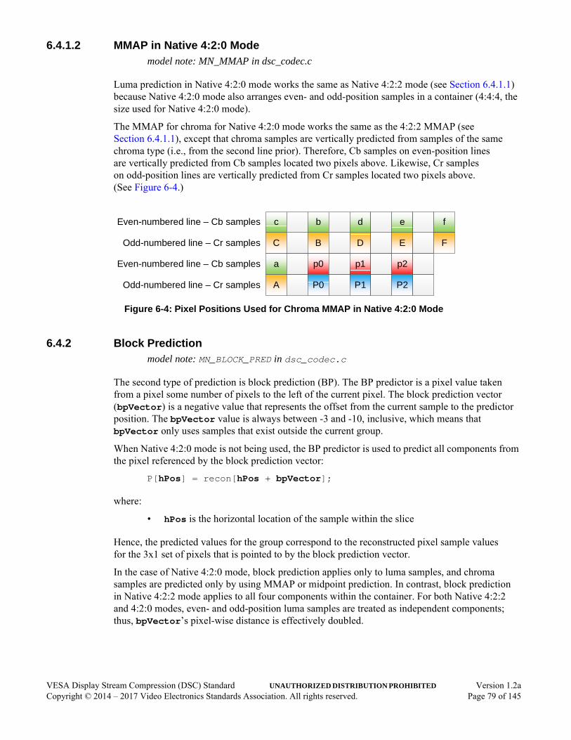
6.4.1.2 MMAP in Native 4:2:0 Modemodel note: MN_MMAP in dsc_codec.c
Luma prediction in Native 4:2:0 mode works the same as Native 4:2:2 mode (see Section 6.4.1.1) because Native 4:2:0 mode also arranges even- and odd-position samples in a container (4:4:4, the size used for Native 4:2:0 mode).
The MMAP for chroma for Native 4:2:0 mode works the same as the 4:2:2 MMAP (see Section 6.4.1.1), except that chroma samples are vertically predicted from samples of the same chroma type (i.e., from the second line prior). Therefore, Cb samples on even-position lines are vertically predicted from Cb samples located two pixels above. Likewise, Cr samples on odd-position lines are vertically predicted from Cr samples located two pixels above. (See Figure 6-4.)
Figure 6-4: Pixel Positions Used for Chroma MMAP in Native 4:2:0 Mode
6.4.2 Block Predictionmodel note: MN_BLOCK_PRED in dsc_codec.c
The second type of prediction is block prediction (BP). The BP predictor is a pixel value taken from a pixel some number of pixels to the left of the current pixel. The block prediction vector (bpVector) is a negative value that represents the offset from the current sample to the predictor position. The bpVector value is always between -3 and -10, inclusive, which means that bpVector only uses samples that exist outside the current group.
When Native 4:2:0 mode is not being used, the BP predictor is used to predict all components from the pixel referenced by the block prediction vector:
P[hPos] = recon[hPos + bpVector];
where:
• hPos is the horizontal location of the sample within the slice
Hence, the predicted values for the group correspond to the reconstructed pixel sample values for the 3x1 set of pixels that is pointed to by the block prediction vector.
In the case of Native 4:2:0 mode, block prediction applies only to luma samples, and chroma samples are predicted only by using MMAP or midpoint prediction. In contrast, block prediction in Native 4:2:2 mode applies to all four components within the container. For both Native 4:2:2 and 4:2:0 modes, even- and odd-position luma samples are treated as independent components; thus, bpVector’s pixel-wise distance is effectively doubled.
C B D E
c b d e f
A P0 P1 P2
a p0 p1 p2
F
Even-numbered line – Cb samples
Odd-numbered line – Cr samples
Even-numbered line – Cb samples
Odd-numbered line – Cr samples
VESA Display Stream Compression (DSC) Standard UNAUTHORIZED DISTRIBUTION PROHIBITED Version 1.2aCopyright © 2014 – 2017 Video Electronics Standards Association. All rights reserved. Page 79 of 145

6.4.3 Midpoint Predictionmodel note: MN_MIDPOINT_PRED in dsc_codec.c
The last type of prediction is midpoint prediction (MPP). The MPP predictor is a value at or near the range’s midpoint. The predictor depends on the rightmost reconstructed sample value of the previous group, even if the previous group is on the previous line:
P = (1 << (cpntBitDepth - 1)) + (prevRecon & ((1 << qLevel) - 1));
where:
• cpntBitDepth is the bit depth of the component being predicted
• prevRecon is the rightmost reconstructed sample from the previous group
• qLevel is the quantization level that applies to the current component
For the first group of a slice, the prevRecon value in this formula is programmed to 0.
6.4.4 Prediction Method DecisionThe bitstream does not explicitly signal the BP vs. MMAP predictor method; therefore, the encoder and decoder shall both follow identical processes to determine which prediction method to use for each group. An encoder first selects between BP and MMAP, then selects between BP or MMAP and MPP, as described in the sections that follow. BP is never used for chroma samples when Native 4:2:0 mode is used.
6.4.4.1 Selection between Block and Modified Median-Adaptive Predictionmodel note: MN_BP_SEARCH in dsc_codec.c
DSC encoders are required to support BP. Encoders can choose to disable block prediction in the stream (either because the attached decoder does not support block prediction, or because the picture would not benefit from block prediction) by clearing block_pred_enable to 0 in the current PPS. In this case, MMAP is always selected over block prediction, and the algorithms in this section are not used.
The decision of whether to use BP or MMAP is made on a group basis, using only information from the previous line. This means that the decision can be made up to one line time in advance of processing the current group. In the example illustrated in Figure 6-5, the group starts at a horizontal location of hPos pixels from the leftmost pixel column in the slice, where hPos is a multiple of 3.
VESA Display Stream Compression (DSC) Standard UNAUTHORIZED DISTRIBUTION PROHIBITED Version 1.2aCopyright © 2014 – 2017 Video Electronics Standards Association. All rights reserved. Page 80 of 145
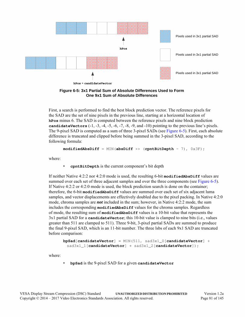
Figure 6-5: 3x1 Partial Sum of Absolute Differences Used to FormOne 9x1 Sum of Absolute Differences
First, a search is performed to find the best block prediction vector. The reference pixels for the SAD are the set of nine pixels in the previous line, starting at a horizontal location of hPos minus 6. The SAD is computed between the reference pixels and nine block prediction candidateVectors (-1, -3, -4, -5, -6, -7, -8, -9, and -10) pointing to the previous line’s pixels. The 9-pixel SAD is computed as a sum of three 3-pixel SADs (see Figure 6-5). First, each absolute difference is truncated and clipped before being summed in the 3-pixel SAD, according to the following formula:
modifiedAbsDiff = MIN(absDiff >> (cpntBitDepth - 7), 0x3F);
where:
• cpntBitDepth is the current component’s bit depth
If neither Native 4:2:2 nor 4:2:0 mode is used, the resulting 6-bit modifiedAbsDiff values are summed over each set of three adjacent samples and over the three components (see Figure 6-5). If Native 4:2:2 or 4:2:0 mode is used, the block prediction search is done on the container; therefore, the 6-bit modifiedAbsDiff values are summed over each set of six adjacent luma samples, and vector displacements are effectively doubled due to the pixel packing. In Native 4:2:0 mode, chroma samples are not included in the sum; however, in Native 4:2:2 mode, the sum includes the corresponding modifiedAbsDiff values for the chroma samples. Regardless of mode, the resulting sum of modifiedAbsDiff values is a 10-bit value that represents the 3x1 partial SAD for a candidateVector; this 10-bit value is clamped to nine bits (i.e., values greater than 511 are clamped to 511). Three 9-bit, 3-pixel partial SADs are summed to produce the final 9-pixel SAD, which is an 11-bit number. The three lsbs of each 9x1 SAD are truncated before comparison:
bpSad[candidateVector] = MIN(511, sad3x1_0[candidateVector] + sad3x1_1[candidateVector] + sad3x1_2[candidateVector]);
where:
• bpSad is the 9-pixel SAD for a given candidateVector
hPos
hPos + candidateVector
Pixels used in 3x1 partial SAD
Pixels used in 3x1 partial SAD
Pixels used in 3x1 partial SAD
VESA Display Stream Compression (DSC) Standard UNAUTHORIZED DISTRIBUTION PROHIBITED Version 1.2aCopyright © 2014 – 2017 Video Electronics Standards Association. All rights reserved. Page 81 of 145

The nine 9-pixel SADs are compared to one another and the lowest SAD is selected, with ties broken by selecting the smallest magnitude bpVector, which is equal to the candidateVector with the lowest SAD. If the lowest SAD bpVector is -1, the bpCount counter is reset to 0 and MMAP is selected for this group. If the lowest SAD bpVector is not -1, the bpVector for the group becomes the vector with the lowest SAD, and the bpCount counter is incremented unless hPos is less than 9.
Note that the BP decision applies to groups in 4:4:4 mode. In Native 4:2:2 and 4:2:0 modes, the BP decision applies to groups within the container. BP is selected for a given group if the following conditions are all true:
• bpCount is greater than or equal to 3.
• lastEdgeCount is less than 3. Its value represents the number of pixels that have passed since an “edge” occurred. An “edge” occurs when ABS(currentSample - leftSample) > 32 << (bits_per_component - 8) for any component.
• Current group is not a partial group at the end of a slice line (e.g., if the slice width is not evenly divisible by 3, the last group of each line would be a partial group and BP would not be selected).
6.4.4.2 Selection between Block/Modified Median-Adaptive and Midpoint Predictionmodel note: MN_ENC_MPP_SELECT in dsc_codec.c
Note: In the following, the outcome of the BP vs. MMAP decision for the current group (described in Section 6.4.4.1) is referred to as “BP/MMAP.”
The encoder shall decide whether to use BP/MMAP, based on the size of the quantized residuals that would be generated if BP/MMAP is selected. The maximum residual size for BP/MMAP is computed for each of the units. If the maximum residual size for any unit is greater than or equal to cpntBitDepth - qLevel for that unit, MPP shall be selected for that unit. The residual size for an MPP residual is always considered to be equal to cpntBitDepth - qLevel.
In addition, the encoder shall select MPP to enforce a minimum data rate that avoids underflow. The encoder algorithm used to force MPP (forceMpp) is described in Section 6.8.1.
VESA Display Stream Compression (DSC) Standard UNAUTHORIZED DISTRIBUTION PROHIBITED Version 1.2aCopyright © 2014 – 2017 Video Electronics Standards Association. All rights reserved. Page 82 of 145

6.4.5 Quantizationmodel note: MN_ENC_QUANTIZATION in dsc_codec.c
The predicted value of each sample of the pixel is subtracted from the corresponding input samples to form the residual sample values E.
E = x - Px; // x is input, Px is predicted value
Each residual value E is quantized using division, with truncation by a divisor that is a power of 2, and using a rounding value that is 1 less than half the divisor:
if (E < 0) QE = -((ROUND - E) >> qLevel);
else QE = ((E + ROUND) >> qLevel);
// the >> operator is shift right with truncation, the same as in C
where:
ROUND = (qLevel > 0) ? ((1 << qLevel) / 2 - 1) : 0;
The qLevel value can be different for luma and chroma, and is determined by the rate control (RC) algorithm. See Section 6.8.6 for further details.
MPP quantized residuals are checked to ensure that their sizes do not exceed:
cpntBitDepth - qLevel
where:
• qLevel is the quantization level for the component type (luma or chroma)
• cpntBitDepth is the current component’s bit depth
If an MPP residual exceeds this size, the residual is changed to the nearest residual with a size of cpntBitDepth - qLevel.
Note: The residual check performed for MPP is not needed by MMAP or BP.
6.4.6 Inverse Quantization and Reconstructionmodel note: MN_IQ_RECON in dsc_codec.c
The encoder must follow the same process used in the decoder to determine the reconstructed sample values. For pixels that are predicted using MMAP, BP, or MPP, the reconstructed sample (reconSample) value shall be equal to the following:
reconSample = CLAMP(predSample + (quantized_residual << qLevel), 0, maxVal);
where:
• predSample is the predicted sample value
• quantized_residual is the quantized residual
• qLevel is the quantization level for the component type (luma or chroma)
• maxVal is the component type’s maximum possible sample value
VESA Display Stream Compression (DSC) Standard UNAUTHORIZED DISTRIBUTION PROHIBITED Version 1.2aCopyright © 2014 – 2017 Video Electronics Standards Association. All rights reserved. Page 83 of 145
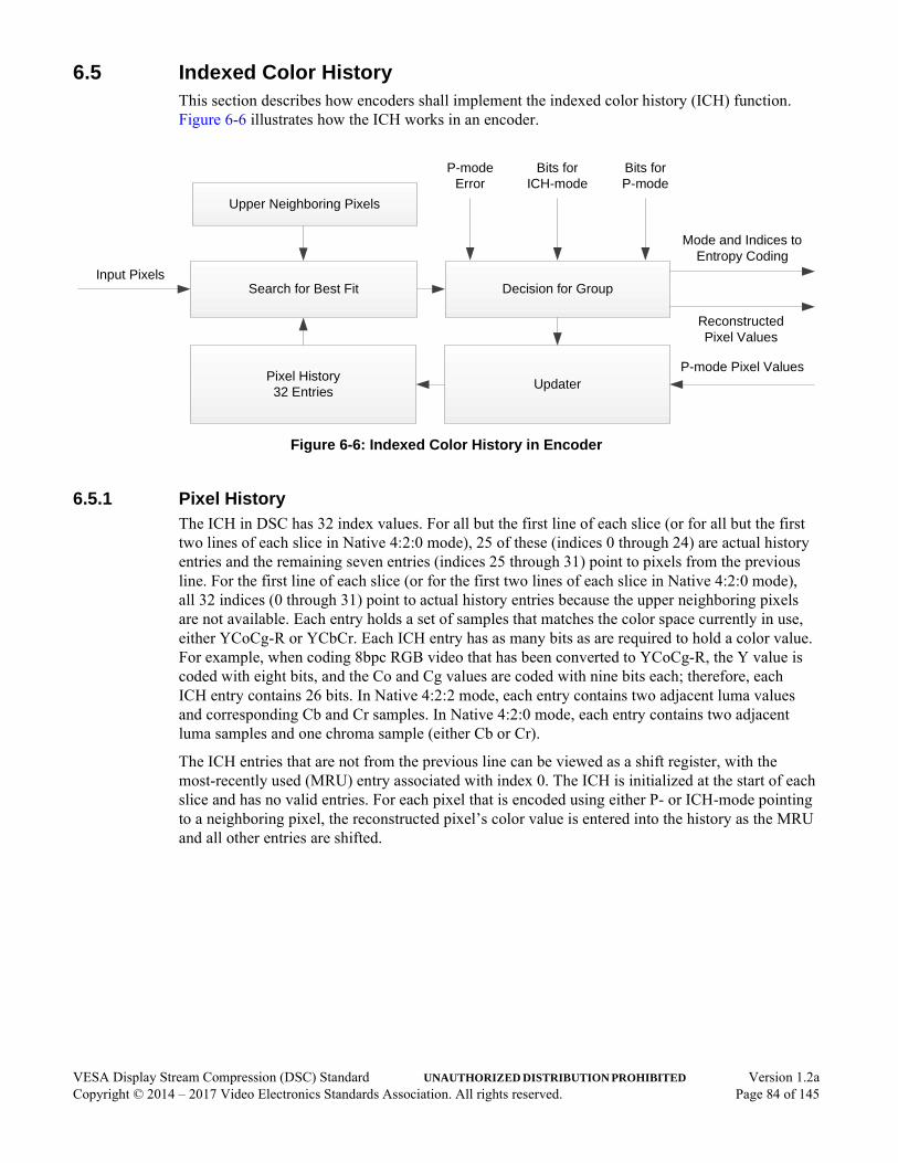
6.5 Indexed Color HistoryThis section describes how encoders shall implement the indexed color history (ICH) function. Figure 6-6 illustrates how the ICH works in an encoder.
Figure 6-6: Indexed Color History in Encoder
6.5.1 Pixel HistoryThe ICH in DSC has 32 index values. For all but the first line of each slice (or for all but the first two lines of each slice in Native 4:2:0 mode), 25 of these (indices 0 through 24) are actual history entries and the remaining seven entries (indices 25 through 31) point to pixels from the previous line. For the first line of each slice (or for the first two lines of each slice in Native 4:2:0 mode), all 32 indices (0 through 31) point to actual history entries because the upper neighboring pixels are not available. Each entry holds a set of samples that matches the color space currently in use, either YCoCg-R or YCbCr. Each ICH entry has as many bits as are required to hold a color value. For example, when coding 8bpc RGB video that has been converted to YCoCg-R, the Y value is coded with eight bits, and the Co and Cg values are coded with nine bits each; therefore, each ICH entry contains 26 bits. In Native 4:2:2 mode, each entry contains two adjacent luma values and corresponding Cb and Cr samples. In Native 4:2:0 mode, each entry contains two adjacent luma samples and one chroma sample (either Cb or Cr).
The ICH entries that are not from the previous line can be viewed as a shift register, with the most-recently used (MRU) entry associated with index 0. The ICH is initialized at the start of each slice and has no valid entries. For each pixel that is encoded using either P- or ICH-mode pointing to a neighboring pixel, the reconstructed pixel’s color value is entered into the history as the MRU and all other entries are shifted.
Pixel History32 Entries
Search for Best FitInput Pixels
Updater
Decision for Group
Mode and Indices to Entropy Coding
Upper Neighboring Pixels
P-modeError
Bits forICH-mode
Bits forP-mode
Reconstructed Pixel Values
P-mode Pixel Values
VESA Display Stream Compression (DSC) Standard UNAUTHORIZED DISTRIBUTION PROHIBITED Version 1.2aCopyright © 2014 – 2017 Video Electronics Standards Association. All rights reserved. Page 84 of 145

For lines after the first line of a slice (or for lines that follow the second line of a slice in Native 4:2:0 mode), index 24 is the least-recently used (LRU) entry of the shift register history, and indices 25 through 31 point to pixels from the previous line. For the first group of a line, these seven pixels are the first seven pixels from the previous line. For subsequent groups, the seven pixels are the two adjacent pixels to the left of the current group in the previous line, the pixels above the current group in the previous line, and two adjacent pixels to the right of the current group in the previous line. If any of the seven pixels fall outside the slice boundary (e.g., for the last or second-to-last group of a slice line), the seven pixels used are the last seven pixels in the previous slice line.
For Native 4:2:0 mode, each ICH entry contains two adjacent luma samples and a chroma sample (Cb for even-position lines and Cr for odd-position lines) that can be used to represent two adjacent pixels and one of the chroma components. The chroma type (Cb or Cr), however, is not recorded; thus, the chroma value may be used to fill in either a Cb or Cr component. When referring to previous lines, the chroma type refers to a sample on the second line prior because that line contains the chroma type.
In Native 4:2:2 and 4:2:0 modes, the pairs of adjacent luma samples on the previous line can start on any pixel boundary and are not restricted to even pairings. (See Figure 6-7 and Figure 6-8, respectively.) As illustrated in the figure, the referenced luma samples are the six samples above the current group in the previous line and one adjacent sample to the left and right of the current group in the previous line. At the left and right edges of the slice, the window of referenced pixel values is shifted so that referenced sample values always come from the active raster.
Figure 6-7: Pixels with Chroma in Native 4:2:2 Mode
Y0 Y1
Cb
Ye0
Yo0
Cb0
Ye1
Yo1
Cb1
Ye2
Yo2
Cb2
Ye3
Yo3
Cb3
Ye24
Yo24
Y0 Y1
Y2 Y3
Cb
Y4 Y5
Cb
Y-1 Y3Y2 Y4 Y5 Y6I0 I1 I2 I3 I24...
... Cb Cb Cb Cb
Current line
Previous line
ICH storage:
I25 I26 I27 I28 I29 I30 I31
Cr0 Cr1 Cr2 Cr3
Cr Cr Cr Cr
Cr Cr Cr
Cb24
Cr24
VESA Display Stream Compression (DSC) Standard UNAUTHORIZED DISTRIBUTION PROHIBITED Version 1.2aCopyright © 2014 – 2017 Video Electronics Standards Association. All rights reserved. Page 85 of 145

Figure 6-8: Pixels with Chroma in Native 4:2:0 Mode (Even-position Line Example)
6.5.2 Indexed Color History UpdatesFor each group coded using P-mode, the rightmost reconstructed pixel value becomes the MRU (ICH entry 0), the middle reconstructed pixel becomes the second MRU (ICH entry 1), and the leftmost reconstructed pixel becomes the third MRU (ICH entry 2). The current entries shift down by three, and the three LRU entries drop off. Because there is no redundancy checking, it is possible to have multiple ICH entries with the same pixel value. Reconstructed values are used so that the decoder and encoder have identical sets of values in their respective ICHs.
For each group that is encoded using ICH-mode, three ICH indices are referenced. Hence, there are either three indices (e.g., I0, I1, I2), two indices (e.g., I1, I2), or one index (e.g., I2) that are used to update the ICH. The ICH state changes only on group times and not on pixel times; therefore, these three indices point to the same ICH state. If there are fewer than three unique indices, the first replicated index is ignored for the purposes of ICH updates (e.g., if indices I5, I21, and I5 are selected, the first I5 is ignored).
The I2 value then becomes the MRU, the I1 (if present) value becomes the second MRU, and the I0 (if present) value becomes the third MRU. Subsequent values in the ICH are:
• Shifted down by three if the current index is less than three of the indices (e.g., I0, I1, and I2),
• Shifted down by two if the current index is less than two of the indices (e.g., I1, I2),
• Shifted down by one if the current index is less than one index (e.g., I2), or
• Not shifted down if the current index is greater than all the indices.
This update process is the same, regardless of whether the ICH indices refer to pixel values in the shift register or from the previous line.
Examples of ICH updates are illustrated in Figure 6-9 and Figure 6-10. The values of P0, P1, …, P31 represent the sample values in the ICH before the update. In 4:4:4 mode, each P represents a set of three samples that form a single pixel. In Native 4:2:0 or 4:2:2 mode, each P represents a set of three or four samples, respectively, that form a single pixel within the container.
Y0 Y1
Cb0
Ye0
Yo0
C0
Ye1
Yo1
C1
Ye2
Yo2
C2
Ye3
Yo3
C3
Ye24
Yo24
C24 Y0 Y1
Y2 Y3
Cb1
Y4 Y5
Cb2
Y-1 Y3Y2 Y4 Y5 Y6
Cr0 Cr1 Cr2 Cr3
I0 I1 I2 I3 I24...
...
Y0 Y1Y-1 Y3Y2 Y4 Y5 Y6
Cb0 Cb1 Cb2 Cb3
Current line
Previous line
Second line prior
I25 I26 I27 I28 I29 I30 I31
e.g., I25 uses Y-1 and Y0 from previous line
and Cb0 from second line prior
ICH storage:
VESA Display Stream Compression (DSC) Standard UNAUTHORIZED DISTRIBUTION PROHIBITED Version 1.2aCopyright © 2014 – 2017 Video Electronics Standards Association. All rights reserved. Page 86 of 145

Figure 6-9: Indexed Color History State Update Example – Three Unique Indices Selected
If there are fewer than three unique history indices, the first occurrence of a replicated index is ignored for the purposes of updating the ICH state (see Figure 6-10), and only the rightmost unique entries of the three pixels in the group are used to update the history.
Figure 6-10: Indexed Color History State Update Example – Two Unique Indices Selected
The last (or partial) group of each slice line does not result in an ICH update. In addition, if the current PPS indicates more than one slice per line (pic_width != slice_width), the ICH entries in the shift register are invalidated at the beginning of each line within the slice.
P0 P1 P2 P3 P4 P5 P6 P7 P31
Select I0, I6, I3
P3 P6 P0 P1 P2 P4 P5 P7 P31
…
…
Top Bottom
P0 P1 P2 P3 P4 P5 P6 P7 P31
Select I3, I6, I3
P3 P6 P0 P1 P2 P4 P5 P7 P31
…
…
(The state update ignores the first I3 because I3 appears again later)
Top Bottom
VESA Display Stream Compression (DSC) Standard UNAUTHORIZED DISTRIBUTION PROHIBITED Version 1.2aCopyright © 2014 – 2017 Video Electronics Standards Association. All rights reserved. Page 87 of 145
6.5.3 Encoder DecisionsThe encoder makes the decisions of when to code a group in ICH-mode. These decisions are independent of the decoder design, as there is no matching algorithm in the decoder. However, this Standard defines the specific algorithm that the encoder uses for ICH selection.
6.5.3.1 Indexed Color History Candidate Index Selectionmodel note: MN_ENC_ICH_IDX_SELECT in dsc_codec.c
For each pixel within the group, the encoder searches over the 32 ICH entries and finds the best entry for each pixel with the smallest weighted SAD of per-component errors (weightedSad):
weightedSad = lumaWeight * ABS(Y_orig - Y_history) + ABS(Co_orig - Co_history) + ABS(Cg_orig - Cg_history) + 2 * ABS(Y2_orig - Y2_history)
where:
• Y_orig, Co_orig, Cg_orig, and Y2_orig correspond to the sample values of the original image pixels
• Y_history, Co_history, Cg_history, and Y2_history correspond with sample values of an ICH entry
• lumaWeight is 1 if native_420 is set to 1; otherwise, lumaWeight is 2
Note: In Native 4:2:0 mode, Co_orig and Co_history represent odd-position pixel luma samples, and Cg_orig and Cg_history represent either Cb or Cr samples depending on whether an even- or odd-position line is being processed. Y2_orig and Y2_history are used only in Native 4:2:2 mode.
If the weightedSad is the same for two indices for a given pixel, the smaller of the two indices is selected for that pixel.
6.5.3.2 Indexed Color History- vs. Predictive-Mode Decisionmodel note: MN_ENC_ICH_MODE_SELECT in dsc_codec.c
The encoder selects ICH-mode for a group based on a set of conditions.
The first condition is that at least one ICH entry must exist such that the coding error(i.e., ABS(inputSample - ichSample)) of each component sample, of each group, must not exceed a certain threshold.
where:
• inputSample is the original picture sample from the input to the encoder
• ichSample is the sample value for the “one ICH entry” that is mentioned
VESA Display Stream Compression (DSC) Standard UNAUTHORIZED DISTRIBUTION PROHIBITED Version 1.2aCopyright © 2014 – 2017 Video Electronics Standards Association. All rights reserved. Page 88 of 145

Note: The “one ICH entry” that is used can be different for each of the three pixels within the group.
This threshold is derived as follows:
modifiedQp = MIN(masterQp + 2, 2 * bits_per_component - 1);maxQerr = (1 << MapQpToQlevel(modifiedQp)) / 2;
The MapQpToQlevel() function performs the mapping of modifiedQp to luma and chroma qLevel, as described in Section 6.8.6. The encoder finds the absolute difference for each component between each input pixel and the corresponding components in all the ICH entries. The encoder then compares those differences to the maximum quantization error values that apply to each pixel to determine whether any entry is suitable. If there is at least one suitable ICH entry for each of the pixels in the group, ICH-mode is a valid option for the group. It is not necessary for the entries that correspond to the candidate indices discussed in Section 6.5.3.1 to meet this condition, as long as one or more entries among the 32 ICH entries meets this condition.
After the optimal ICH entries are determined using the method described in Section 6.5.3.1, the encoder decides whether to use ICH- or P-mode. This decision is made based on the maximum unit-wise errors for each mode, and the numbers of bits that would be required to code each mode. The unit-wise errors are determined as follows:
maxYErrIchMode = MaxOverPixelsInGroup(ABS(Y_orig - Y_ich) >> shift);
maxCoErrIchMode = MaxOverPixelsInGroup(ABS(Co_orig - Co_ich) >> shift);
maxCgErrIchMode = MaxOverPixelsInGroup(ABS(Cg_orig - Cg_ich) >> shift);
maxY2ErrIchMode = MaxOverPixelsInGroup(ABS(Y2_orig - Y2_ich) >> shift);
maxYErrPMode = MaxOverPixelsInGroup(ABS(Y_orig - Y_recon) >> shift);
maxCoErrPMode = MaxOverPixelsInGroup(ABS(Co_orig - Co_recon) >> shift);
maxCgErrPMode = MaxOverPixelsInGroup(ABS(Cg_orig - Cg_recon) >> shift);
maxY2ErrPMode = MaxOverPixelsInGroup(ABS(Y2_orig - Y2_recon) >> shift);
where:
• shift is equal to bits_per_component - 8• Y_orig, Co_orig, Cg_orig, and Y2_orig are the original samples
(Y/Co/Cg/unused, Y/Cb/Cr/unused, or Y/Cb/Cr/Y2)
• Y_ich, Co_ich, and Cg_ich are the samples of the selected ICH entry
• Y_recon, Co_recon, Cg_recon, and Y2_recon are the samples of the reconstructed pixels if P-mode is selected
VESA Display Stream Compression (DSC) Standard UNAUTHORIZED DISTRIBUTION PROHIBITED Version 1.2aCopyright © 2014 – 2017 Video Electronics Standards Association. All rights reserved. Page 89 of 145
In Native 4:2:2 mode:
• maxYErrIchMode and maxYErrPMode are computed over the group’s even-position luma samples
• maxY2ErrIchMode and maxY2ErrPMode are computed over the group’s odd-position luma samples
The bitsIchMode value represents the number of bits required to code the group in ICH-mode. The bitsPMode value represents the number of bits required to code the group in P-mode. The final ICH decision is made as follows:
if (dsc_version_minor == 1){
logErrIchMode = 2 * ceil_log2(maxYErrIchMode) + ceil_log2(maxCoErrIchMode) + ceil_log2(maxCgErrIchMode);
logErrPMode = 2 * ceil_log2(maxYErrPMode) + ceil_log2(maxCoErrPMode) + ceil_log2(maxCgErrPMode);
} else if (!native_422) {
logErrIchMode = ceil_log2(maxYErrIchMode) +
ceil_log2(maxCoErrIchMode) + ceil_log2(maxCgErrIchMode);
logErrPMode = ceil_log2(maxYErrPMode) +
ceil_log2(maxCoErrPMode) + ceil_log2(maxCgErrPMode);
} else { // Native 4:2:2 mode
logErrIchMode = ceil_log2(maxYErrIchMode) + ceil_log2(maxY2ErrIchMode) + ceil_log2(maxCoErrIchMode) + ceil_log2(maxCgErrIchMode);
logErrPMode = ceil_log2(maxYErrPMode) + ceil_log2(maxY2ErrPMode) + ceil_log2(maxCoErrPMode) + ceil_log2(maxCgErrPMode);
}
if (dsc_version_minor == 1 || nextIsVeryFlat)
useIch = (logErrIchMode <= logErrPMode) && (bitsIchMode + 4 * logErrIchMode < bitsPMode + 4 * logErrPMode);
else
useIch = (bitsIchMode + 4 * logErrIchMode < bitsPMode + 4 * logErrPMode);
VESA Display Stream Compression (DSC) Standard UNAUTHORIZED DISTRIBUTION PROHIBITED Version 1.2aCopyright © 2014 – 2017 Video Electronics Standards Association. All rights reserved. Page 90 of 145

The nextIsVeryFlat value is true when the “very flat” flatness search described in Section 6.8.5.1 results in a “very flat” determination for the next group in the current line. The first group of every slice is never coded in ICH-mode because the ICH is reset at the first pixel and there are no valid entries. The first group of a line that is not the first line of a slice can use ICH-mode to point to nearby pixels from the previous line. If the last group of a slice extends beyond the edge of the raster, pixel replication is used for ICH selection (or equivalently, the ICH index can be repeated), and the final ICH decision is made as described above. ICH-mode is never selected if forceMpp is used for the group (see Section 6.8.1).
6.5.3.3 Full Error Precision for ICH DecisionFor some implementations, particularly at bit depths greater than or equal to 10bpc, it can be advantageous to make slight modifications to the ICH decision process. Implementations shall use either the method described in this section or Section 6.5.3.2 to compute the errors used for the ICH decision. The method described in Section 6.5.3.2 shall be used if dsc_version_minor is equal to 1.
For implementations that choose to implement the alternative decision, the error computation (for maxYErrIchMode, maxCoErrIchMode, etc.) described in Section 6.5.3.2 shall use a shift value of 0, regardless of the component bit depth (i.e., the full precision of the errors shall be used to compute the log error costs). The remainder of the calculation shall be the same as that described in Section 6.5.3.2.
6.6 Entropy EncoderThe entropy encoder is required to generate bits according to the substream syntax listed in Section 4.5.
The Slice Layer contains three or four multiplexed substreams. This section describes how encoders create substreams. Section 6.7 describes how the substreams are multiplexed together to form a slice.
Each group is coded in either P- or ICH-mode. P-mode uses the delta size unit-variable length coding (DSU-VLC) scheme, as described in Section 6.6.1. ICH-mode uses a special escape code, as described in Section 6.6.2.
Each line of a slice is required to start on a group boundary. If slice_width (or slice_width/2 in Native 4:2:2 or 4:2:0 mode) is not evenly divisible by three, the last group of each line might contain fewer than a full group’s worth of pixels. If that last group is coded in P-mode, any residuals that correspond with pixels beyond the edge of the slice are cleared to 0. If that last group is coded in ICH-mode, the index used for the rightmost pixel shall be replicated to pad the entropy coding unit to complete the syntax.
6.6.1 Delta Size Unit-Variable Length CodingDelta size unit-variable length coding (DSU-VLC), which is used in P-mode, defines the two parts of each unit – prefix and suffix. The prefix indicates the size of the residual data that follows in the suffix. Three residuals are coded within each suffix.
The entropy coding algorithm makes a size prediction based on the sizes of decoded data from the previous unit of the same component type:
• If the predicted size is sufficient to hold the new residual data, the prefix code indicates “no change,” and each residual is contained within as many bits as the predicted size, with leading 0s inserted or sign extension used if the residuals are small.
VESA Display Stream Compression (DSC) Standard UNAUTHORIZED DISTRIBUTION PROHIBITED Version 1.2aCopyright © 2014 – 2017 Video Electronics Standards Association. All rights reserved. Page 91 of 145

• If the predicted size is too small to hold any of the three residuals in the unit, the prefix code indicates the amount to increase the size to accommodate the largest of the three residuals. Each residual is then contained within as many bits as the new size, with leading 0s inserted or sign extension used if some residuals are small.
If MPP is selected, the required size is always cpntBitDepth - qLevel, even if the residual sizes could have been coded in fewer bits.
Size prediction is done independently for each component. One value that is needed is the change in qLevel for the current component from the previous unit to the current unit (qLevelChange). The required sizes for each quantized residual within the previous unit (requiredSize[0], requiredSize[1], and requiredSize[2]) are also needed. From these, the predicted size (adjPredictedSize) for the unit is provided by the following:
predictedSize = (requiredSize[0] + requiredSize[1] + 2 * requiredSize[2] + 2) >> 2;
adjPredictedSize = CLAMP(predictedSize - qLevelChange, 0, maxSize - 1);
where:
• maxSize is the current component’s maximum possible residual size
If the previous group is ICH-coded, the predictedSize that is used comes from the most-recent P-mode group. In this case, the qLevelChange that is used is still based on a comparison of the QP between the previous (ICH-coded) group and current group. By specifying a maximum value in the CLAMP() function, the coding allows either MPP or MMAP/BP to be selected for the next group. For the first group of a slice, the adjPredictedSize is equal to 0.
For Native 4:2:2 and 4:2:0 modes, the size predictions for the even- and odd-position luma units are independent.
The prefix coding is a modified unary code. There are three different codebooks:
• If coding the first luma unit of a group and the previous group is P-mode-coded, a straight unary code is used; the size increase is indicated by the number of “0” bits that precede a trailing “1” bit.
• If coding the first luma unit of a group and the previous group is ICH-mode-coded, the single “1” bit indicates that ICH-mode is used again; therefore, each code is offset by 1. For example, “01” means that there is no size change, “001” means that the size is increased by one, etc. For the maximum-length code (i.e., where the size is equal to bits_per_component - qLevelY), the trailing “1” bit is not coded because the decoder can infer the bit.
• For units other than the first luma unit of a group, a unary code is used as in the first codebook, except for the maximum-length code (i.e., where the size is equal to either cpntBitDepth_Y - qLevelY or cpntBitDepth_C - qLevelC, depending on the component type). In this case, only the “0” bits are coded because the decoder can infer the trailing “1” bit.
VESA Display Stream Compression (DSC) Standard UNAUTHORIZED DISTRIBUTION PROHIBITED Version 1.2aCopyright © 2014 – 2017 Video Electronics Standards Association. All rights reserved. Page 92 of 145

6.6.2 Indexed Color History CodingIndexed Color History coding (ICH-mode) is signaled using an escape code on the first luma unit of a group. If the previous group was coded in P-mode, ICH-mode is signaled by indicating a DSU-VLC prefix size for the first unit of a group that is one greater than the maximum length allowed for P-mode (i.e., the DSU-VLC prefix for luma must indicate a size of bits_per_component - qLevelY + 1). Because only one escape code is defined, the trailing “1” bit that is typically used at the end of the prefix is not coded because the decoder infers the bit.
If the previous group is ICH-coded, a prefix_Y consisting of a single “1” bit indicates that ICH-mode continues to be used for the current group. In 4:4:4 and Native 4:2:0 modes, the 5-bit ICH index for the leftmost pixel within the group is coded after prefix_Y within the Y substream. In Native 4:2:2 mode, the 5-bit ICH index for the leftmost pixel within the group is coded within the Y2 substream, with no prefix. In all modes, the 5-bit ICH index for the middle pixel within the group is coded within the Co substream, with no prefix. The 5-bit ICH index for the rightmost pixel within the group is coded within the Cg substream, with no prefix.
Table 6-1 summarizes the prefix codebooks for P- and ICH-modes.
Table 6-1: Prefix Codebooks Summary
Type PreviousGroup Mode
CurrentGroup Mode
Prefix Codebook(Number of “0” and “1” Bits)
First Y P P “0” bits = MAX(0, residualSizeY - adjPredictedSizeY).
“1” bits = One.
First Y P ICH “0” bits = bits_per_component - qLevelY + 1 - adjPredictedSizeY.
“1” bits = None.
First Y ICH P “0” bits = 1 + MAX(0, residualSizeY - adjPredictedSizeY).
“1” bits = One if residualSizeY < bits_per_component - qLevelY; otherwise, none.
First Y ICH ICH “0” bits = None.
“1” bits = One.
Second Y Any P “0” bits = MAX(0, residualSizeY2 - adjPredictedSizeY2).
“1” bits = One if residualSizeY2 < cpntBitDepth_Y - qLevelY; otherwise, none.
Co Any P “0” bits = MAX(0, residualSizeCo - adjPredictedSizeCo).
“1” bits = One if residualSizeCo < cpntBitDepth_C - qLevelC; otherwise, none.
Cg Any P “0” bits = MAX(0, residualSizeCg - adjPredictedSizeCg).
“1” bits = One if residualSizeCg < cpntBitDepth_C - qLevelC; otherwise, none.
Second Y, Co, or Cg
Any ICH “0” bits = None.
“1” bits = None.
VESA Display Stream Compression (DSC) Standard UNAUTHORIZED DISTRIBUTION PROHIBITED Version 1.2aCopyright © 2014 – 2017 Video Electronics Standards Association. All rights reserved. Page 93 of 145

6.6.3 Flatness SignalingThere is a conditional flag in the syntax of luma units, next_flatness_flag, that can occur once every four groups. If the luma unit’s masterQp value is between flatness_min_qp and flatness_max_qp, inclusive, a next_flatness_flag flag is inserted that applies to the supergroup that starts with the group that is the second group to the right. If the next_flatness_flag is set to 1, the next group’s luma unit contains a next_flatness_group syntax element and a conditional next_flatness_type that occurs if the QP for that luma unit is greater than or equal to somewhatFlatQpThresh (i.e., 7 + 2 * (bits_per_component - 8)).
Section 6.8.5 describes the encoder algorithm that is used to determine the values to use for next_flatness_flag, next_flatness_group, and next_flatness_type.
6.6.4 Outputs to Rate ControlFor the purposes of RC, the entropy encoder outputs two values:
• codedBits
• rcSizeGroup
The codedBits value represents the actual number of bits that are used to code a group. The rcSizeGroup value is set to the number of bits that DSU-VLC would have spent coding that group, if the size prediction had exactly matched the actual sizes of the residuals within the group. That is, for each unit within the group, find the largest size of the residuals within the unit, times the number of samples in the unit, plus 1 for a prefix coding the value 0, then add the resulting sizes of the units in the group. If MPP is selected, the value of the largest size of the residual within the unit for this purpose is assumed to be cpntBitDepth - qLevel. If ICH-mode is selected, rcSizeGroup is set to 1 + ichIndicesPerGroup * 5.
These values are assumed to be available after the encoder finishes encoding a group. The values are used in the RC cycle that operates after the current group is encoded.
VESA Display Stream Compression (DSC) Standard UNAUTHORIZED DISTRIBUTION PROHIBITED Version 1.2aCopyright © 2014 – 2017 Video Electronics Standards Association. All rights reserved. Page 94 of 145

6.7 Substream MultiplexerThe substream multiplexer takes the three or four component-wise substreams and combines the substreams into a single slice. Balance FIFOs ensure that the multiplexer has adequate bits to construct mux words, under all conditions. A decoder model dictates how the data is multiplexed. The period between SSM updates is defined to be one group time. Figure 6-11 illustrates the block diagram for substream multiplexing; the Y2 paths are used only for implementations that support Native 4:2:2 mode.
Figure 6-11: Encoder Substream Multiplexer Block Diagram
6.7.1 Balance FIFOsThe Balance FIFOs ensure that the multiplexer has at least one mux word’s worth of data whenever the multiplexer receives a request signal from the decoder model. At the beginning of a slice, each of these FIFOs is filled with muxWordSize + maxSeSize - 1 syntax elements. Each group time, mux words are removed, as dictated by the substream multiplexing, and coded groups are added. For each substream, a Balance FIFO size of (muxWordSize + maxSeSize - 1) entries of maxSeSize bits is sufficient to ensure that the Balance FIFOs do not overflow.
EntropyEncoder Y
EntropyEncoder Co
EntropyEncoder Cg
BalanceFIFO
BalanceFIFO
BalanceFIFO
MultiplexerDecoderModel
Rate Buffer
RateControl
sizeY
requestY
sizeCo
requestCo
sizeCg
requestCg
Up to four mux words
EntropyEncoder Y2
BalanceFIFO
sizeY2
requestY2
VESA Display Stream Compression (DSC) Standard UNAUTHORIZED DISTRIBUTION PROHIBITED Version 1.2aCopyright © 2014 – 2017 Video Electronics Standards Association. All rights reserved. Page 95 of 145

6.7.2 MultiplexerThe multiplexer generates anywhere from zero to four mux words every group time. After the Balance FIFOs are primed, the multiplexer generates one mux word for each active substream as an initial condition (four mux words for Native 4:2:2 mode; three mux words for all other modes) to start the decoder model. The decoder model can signal any combination of requestY, requestCo, requestCg, and requestY2, or none of these, for each group time. If none of these requests are signaled within a given group time, no data is sent to the rate buffer. If one request is signaled for a particular group time, one mux word from that substream is sent to the rate buffer. If more than one request is signaled for a particular group time, mux words from each requested substream are sent to the rate buffer in the following sequence:
1 One mux word for Y.
2 One mux word for Co.
3 One mux word for Cg.
4 One mux word for Y2.
The Balance FIFOs might become empty when a mux word is requested at the end of a slice. If a Balance FIFO is empty, any missing bits within a mux word shall be stuffed with “0” padding bits. In some cases, an entire mux word might consist of stuffed “0” padding bits. If vbr_enable is cleared to 0, the multiplexer stuffs “0” padding bits at the end of a slice to ensure that the total number of bits within the slice is equal to the slice bit budget (sliceBits, described in Table E-1).
6.7.3 Decoder ModelThe decoder model behaves the same as an idealized decoder. The decoder is modeled as a demultiplexer and three or four substream processors (SSPs), each consisting of a funnel shifter and entropy decoder. Each funnel shifter initially contains 1 mux word’s worth of data (note again that only Native 4:2:2 mode uses the Y2 substream). For each group time, the funnel shifter fullness decreases by the size of the syntax element at the front of the funnel shifter. If the new fullness is less than the maximum syntax element size, a request signal is sent and a mux word is added to the funnel shifter.
6.7.4 End of SliceIf vbr_enable is cleared to 0, the substream multiplexer is required to stuff “0” padding bits at the end of the slice so that the total number of bits produced for a slice is equal to 8 * chunk_size * slice_height.
If vbr_enable is set to 1, bit stuffing is bypassed, and the stream ends with the final mux word that is requested by the decoder model.
VESA Display Stream Compression (DSC) Standard UNAUTHORIZED DISTRIBUTION PROHIBITED Version 1.2aCopyright © 2014 – 2017 Video Electronics Standards Association. All rights reserved. Page 96 of 145

6.8 Rate Control AlgorithmThe RC algorithm uses a buffer model. The model is an idealized rate buffer (which behaves like a FIFO) that converts a varying number of bits used to code each group into a specified constant bit rate (CBR). As each group is coded, the number of bits used to code the group is added to the original buffer model fullness, and the number of bits that is to be transmitted per group is then subtracted from the original buffer model fullness. The result is the new buffer model fullness (bufferFullness). bufferFullness is then modified by a linear transformation (i.e., offset and scale) to produce a value (rcModelFullness). The linear transformation is designed to allocate extra bits to the first and (in Native 4:2:0 mode) second line of each slice and fewer bits to other lines, and to bound the maximum number of bits within the encoder buffer at the end of each slice to a specified bound. The first and second line allocation and end-of-slice boundary are configurable.
In CBR mode, the number of bits removed from the buffer model for each group can vary slightly from one group to the next because the specified number of bits per group might include a fractional component. The bits_per_pixel rate is specified using four fractional bits, which produces a resolution of 1/16bpp. If the specified number of bits per group is an integer, the number of bits removed from the buffer model for every group is equal to the specified integer. If the fractional component is not 0, then for each group, the fractional residual resulting from removing an integer number of bits is retained and applied to the next group.
The RC algorithm is designed to maintain the rcModelFullness value between empty (= -rc_model_size) and full (= 0). rcXformOffset and the rcXformScale factor are designed to convert the bufferFullness, which is always non-negative, into the rcModelFullness. The reason the empty level is numerically negative and the full level is 0 relates to the way the linear transformation is designed, is explained in Section 6.8.2.
The RC algorithm dynamically selects a quantization parameter (QP) to maintain rcModelFullness within its valid range and optimize subjective quality. In general, the RC algorithm seeks to code each group with an approximate target number of bits, while the number of bits spent coding each individual group can significantly vary. This behavior allows unexpectedly difficult image features to be efficiently coded while also coding smooth areas with high accuracy, which helps maintain approximately equal subjective quality across the image without wasting bits.
Figure 6-12 illustrates the overall RC algorithm structure.
Figure 6-12: Rate Control Algorithm Structure
For high throughput, an extra clock cycle is allowed within this path
codedGroupSize(previous group)
masterQpLinear
TransformationBuffer Level
Tracker
Select Long-term Parameters,
Based on Range
Short-termQP Adjustment
VESA Display Stream Compression (DSC) Standard UNAUTHORIZED DISTRIBUTION PROHIBITED Version 1.2aCopyright © 2014 – 2017 Video Electronics Standards Association. All rights reserved. Page 97 of 145
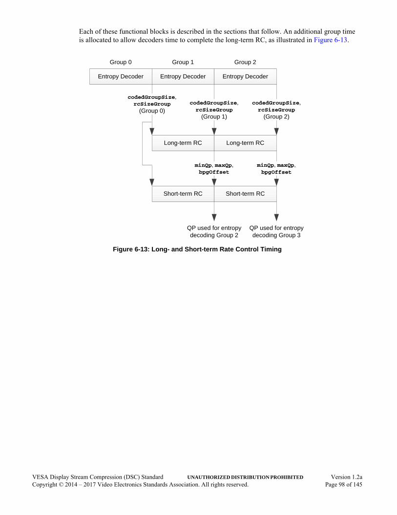
Each of these functional blocks is described in the sections that follow. An additional group time is allocated to allow decoders time to complete the long-term RC, as illustrated in Figure 6-13.
Figure 6-13: Long- and Short-term Rate Control Timing
Entropy Decoder
Short-term RC
Entropy Decoder
Long-term RC
codedGroupSize,rcSizeGroup
(Group 0)
Group 0 Group 1 Group 2
QP used for entropy decoding Group 2
Entropy Decoder
Long-term RC
Short-term RC
codedGroupSize,rcSizeGroup
(Group 1)
minQp, maxQp,bpgOffset
minQp, maxQp,bpgOffset
codedGroupSize,rcSizeGroup
(Group 2)
QP used for entropy decoding Group 3
VESA Display Stream Compression (DSC) Standard UNAUTHORIZED DISTRIBUTION PROHIBITED Version 1.2aCopyright © 2014 – 2017 Video Electronics Standards Association. All rights reserved. Page 98 of 145

6.8.1 Buffer Level TrackerThe buffer level tracker (see Figure 6-14) performs the following processes:
• Keeps track of the buffer model fullness as groups are encoded
• Sends a forceMpp signal to avoid buffer underflows
• Determines chunk boundaries and sizes
Figure 6-14: Buffer Level Tracker
bitsPerGroup
codedGroupSize(previous group)
bufferFullness
forceMpp
Chunk BoundariesadjustmentBits
adjustmentBits
numBitsChunk
Slice Multiplexing
Framer
Accumulate bitsClamped
Bit Stuffing Detection
Register
Register
-
-
+
+
+
VESA Display Stream Compression (DSC) Standard UNAUTHORIZED DISTRIBUTION PROHIBITED Version 1.2aCopyright © 2014 – 2017 Video Electronics Standards Association. All rights reserved. Page 99 of 145

In Figure 6-14, codedGroupSize is an output from the entropy encoder or decoder that indicates how many bits were used to code the previous group. bitsPerGroup is the number of bits allocated for each group, which can vary from group to group:
for (i = 0; i < pixelsInGroup; ++i)
{
pixelCount ++;
if(pixelCount >= initial_xmit_delay){
bpgFracAccum += bits_per_pixel & 0xf; // 4 fractional bits
bitsPerGroup += (bits_per_pixel >> 4) + (bpgFracAccum >> 4);numBitsChunk += (bits_per_pixel >> 4) + (bpgFracAccum >> 4);bpgFracAccum &= 0xf;
}
if(((pixelCount - initial_xmit_delay) % sliceWidth) == 0)bpgFracAccum = 0;
}
where:
• pixelsInGroup is the number of pixels coded by each group. For Native 4:2:2 and 4:2:0 modes, pixelsInGroup refers to the number of container pixels coded by each group.
• pixelCount is a running total of the number of pixels that have been processed.
• bits_per_pixel above is treated as an integer value rather than a fixed-point value with fractional bits.
• bpgFracAccum is the fractional-bit accumulator.
• numBitsChunk corresponds with the number of bits that have been removed from the rate buffer model for the current chunk.
• sliceWidth is equal to slice_width if native_422 and native_420 are both cleared to 0; if native_422 or native_420 is set to 1, sliceWidth is equal to slice_width >> 1.
The pixelsInGroup value is generally 3, except when a partial group is being processed at the end of a line, in which case its value is equal to the number of pixels within the group.
VESA Display Stream Compression (DSC) Standard UNAUTHORIZED DISTRIBUTION PROHIBITED Version 1.2aCopyright © 2014 – 2017 Video Electronics Standards Association. All rights reserved. Page 100 of 145

In Figure 6-14, the adjustmentBits value is typically 0, except when the last group of a chunk is being processed. In that case, adjustmentBits corresponds to the number of additional bits that are required to make the chunk size an integer number of bytes. The slice multiplexing framer is responsible for determining the adjustmentBits value for each line. The framer tracks how many bits have been removed for each slice line:
if(pixelsInGroup + chunkPixelTimes >= sliceWidth)
{
pixelsRemaining = sliceWidth - chunkPixelTimes;
modBpgFracAccum = prevBpgFracAccum + (pixelsRemaining *bits_per_pixel) & 0xf;
modBitsPerGroup = ((pixelsRemaining * bits_per_pixel) >> 4) +(modBpgFracAccum >> 4);
if(vbr_enable) {vbrChunkSize = ceil((prevNumBitsChunk + modBitsPerGroup -bitsClamped) / 8);
adjustmentBits = 8 * vbrChunkSize - (prevNumBitsChunk +modBitsPerGroup - bitsClamped);
} else
adjustmentBits = 8 * chunk_size - (prevNumBitsChunk +modBitsPerGroup);
numBitsChunk = prevNumBitsChunk - 8 * chunk_size;} else
adjustmentBits = 0;
where:
• chunkPixelTimes is a counter that counts the number of pixel times (container pixel times in Native 4:2:2 and 4:2:0 modes) that have accumulated for the current chunk, based on summing the values of pixelsInGroup
• bits_per_pixel above is treated as an integer value rather than a fixed-point value with fractional bits.
• prevBpgFracAccum and prevNumBitsChunk are the values of bpgFracAccum and numBitsChunk, respectively, resulting from processing the previous group
• vbrChunkSize is the actual size of the chunk, in units of bytes, when operating in VBR mode
The adjustmentBits value is between 0 and 8, inclusive, and corresponds to the number of “0” padding bits that are stuffed to ensure that the chunk is byte-aligned. In CBR mode, the adjustmentBits value is the same for each slice line because the bpgFracAccum value is reset for each line.
VESA Display Stream Compression (DSC) Standard UNAUTHORIZED DISTRIBUTION PROHIBITED Version 1.2aCopyright © 2014 – 2017 Video Electronics Standards Association. All rights reserved. Page 101 of 145
If vbr_enable is cleared to 0, the “bit stuffing detection” function checks whether the next group could potentially cause an underflow condition (i.e., resulting in a bufferFullness that is less than 0). If so, the forceMpp signal is set to 1, which indicates to the entropy encoder to use MPP to guarantee a minimum bit rate. forceMpp is determined as follows:
forceMpp = (pixelCount > initial_xmit_delay) && (bufferFullness < maxBitsPerGroup - pixelsPerGroup);
where:
• maxBitsPerGroup is equal to (bits_per_pixel * 3 + 15) >> 4
• bits_per_pixel above is treated as an integer value rather than a fixed-point value with fractional bits.
The forceMpp value applies to the group immediately prior to the one that coincides with the end of a chunk:
bugFixCondition = (bits_per_pixel * slice_width) & 0xf;
if ((numBitsChunk + maxBitsPerGroup + 8 > 8 * chunk_size) ||(bugFixCondition && (numBitsChunk + maxBitsPerGroup + 8 ==
chunk_size)))
forceMpp = (pixelCount > initial_xmit_delay) &&(bufferFullness - 8 < maxBitsPerGroup - 3);
This ensures that there is always a sufficient number of bits in the encoder buffer to output the stuffed “0” padding bits.
If vbr_enable is set to 1, bufferFullness is clamped to be no less than 0 if the final modified value would be less than 0:
if(bufferFullness < 0)
{
bitsClamped += -bufferFullness;
bufferFullness = 0;
}
The cumulative amount of the correction for a chunk is stored as bitsClamped, which is used to determine the actual chunk size, as described in Section 4.2.2.
forceMpp is almost never asserted in VBR mode, with the following exception. The forceMpp output is asserted only on the group prior to the one where the adjustmentBits are present, using the same condition as for CBR mode. forceMpp is needed to ensure that the encoder rate buffer has a sufficient number of bits to allow the chunk to end on a byte boundary.
VESA Display Stream Compression (DSC) Standard UNAUTHORIZED DISTRIBUTION PROHIBITED Version 1.2aCopyright © 2014 – 2017 Video Electronics Standards Association. All rights reserved. Page 102 of 145

6.8.2 Linear Transformationmodel note: MN_RC_XFORM and MN_CALC_SCALE_OFFSET in dsc_codec.c
The linear transformation is designed to manage rate buffer fullness over the course of the slice. The transformation has three main functions:
• Maintain constant quality during the initial delay
• Allocate extra bits for the first and second line of each slice
• Ensure that the slice is coded within the correct number of bits, by constraining the final encoder buffer fullness
Linear transformation is provided by the following equation:
rcModelFullness = (rcXformScale * (bufferFullness + rcXformOffset)) >> 3
rcXformOffset is designed to perform the three functions listed above. The rcXformScale factor is applied at the beginning and end of a slice to prevent the RC model’s usable range from shrinking, which helps maintain picture quality (see Figure 6-15).
The range of rcXformOffset values is chosen to be negative, which produces a negative range of rcModelFullness values. This is done so that the rcXformScale factor’s coarse resolution has minimal effect on the rcModelFullness value when the buffer is nearly full. This is because the error term resulting from coarse quantization times a value near 0 results in an error that is near 0. The rcXformScale factor quantization error is instead shifted to the empty end of the rcModelFullness range, where the error has insignificant effect.
The rcXformOffset value starts each slice at a known initial value, initial_offset - rc_model_size. The rcXformOffset modification per group consists of the superposition of several adjustments:
1 During the initial delay, rcXformOffset decreases at a rate of (bits_per_pixel * 3) per group.
2 During the entire slice, rcXformOffset increases at a rate of slice_bpg_offset per group.
3 During the first line of a slice, rcXformOffset decreases at a rate of first_line_bpg_offset per group.
4 During the non-first lines of a slice (which includes the second line), rcXformOffset increases at a rate of nfl_bpg_offset per group.
5 During the second line of a slice, rcXformOffset decreases at a rate of second_line_bpg_offset per group (used only in Native 4:2:0 mode; required to be cleared to 0 when native_420 is also cleared to 0).
6 During the non-second lines of a slice (which includes the first line), rcXformOffset increases at a rate of nsl_bpg_offset per group (used only in Native 4:2:0 mode; required to be cleared to 0 when native_420 is also cleared to 0).
For example, for the first few groups of the slice, rcXformOffset is modified using adjustments 1, 2, 3, and 6 each group time. After rcXformOffset falls below final_offset - rc_model_size, rcXformOffset is not allowed to exceed final_offset - rc_model_size at any point afterward.
These adjustments are done using a precision of 11 fractional bits to ensure accuracy for all slice sizes.
VESA Display Stream Compression (DSC) Standard UNAUTHORIZED DISTRIBUTION PROHIBITED Version 1.2aCopyright © 2014 – 2017 Video Electronics Standards Association. All rights reserved. Page 103 of 145
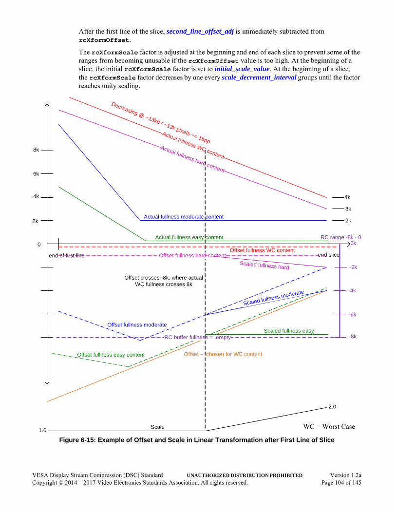
After the first line of the slice, second_line_offset_adj is immediately subtracted from rcXformOffset.
The rcXformScale factor is adjusted at the beginning and end of each slice to prevent some of the ranges from becoming unusable if the rcXformOffset value is too high. At the beginning of a slice, the initial rcXformScale factor is set to initial_scale_value. At the beginning of a slice, the rcXformScale factor decreases by one every scale_decrement_interval groups until the factor reaches unity scaling.
Figure 6-15: Example of Offset and Scale in Linear Transformation after First Line of Slice
end of first line end slice
8k
6k
4k
2k
Actual fullness easy content
Actual fullness moderate content
Actual fullness WC content
RC range -8k - 0
Offset fullness WC content
Offset fullness easy content
Offset fullness moderate
0 0k
-2k
-4k
-6k
-8kRC buffer fullness = empty
Actual fullness hard content
4k
3k
2k
Offset – chosen for WC content
Offset crosses -8k, where actual WC fullness crosses 8k
Offset fullness hard content
Scaled fullness easy
Scale1.0
2.0
Decreasing @ ~13kb / ~13k pixels ~= 1bpp
Scaled fullness moderate
Scaled fullness hard
WC = Worst Case
VESA Display Stream Compression (DSC) Standard UNAUTHORIZED DISTRIBUTION PROHIBITED Version 1.2aCopyright © 2014 – 2017 Video Electronics Standards Association. All rights reserved. Page 104 of 145
When scale_increment_interval is not equal to 0, the rcXformScale factor is also adjusted toward the end of the slice. The rcXformScale is programmed to 9 on the group immediately following the first group, when all the following conditions are met:
• rcXformOffset is greater than -rc_model_size• pixelCount is greater than or equal to initial_xmit_delay• Group is not from the first line of a slice
After this, the rcXformScale factor smoothly ramps up, incrementing by one every scale_increment_interval groups. The encoder is responsible for determining the PPS RC parameters that are discussed in this section. Annex E provides guidance regarding how to derive the parameters.
The net effect of rcXformOffset and the rcXformScale factor is to allow the buffer fullness to grow according to an allocation of extra bits within the first line and a specified initial transmission delay. This allows the buffer to smoothly ramp down the maximum fullness from the end of the first line until the end of the slice, and to guarantee that the number of bits remaining in the buffer at the end of the slice does not exceed:
initial_xmit_delay * pixelsPerGroup * bits_per_pixel - numExtraMuxBits
where:
• numExtraMuxBits is as described in Table E-1
6.8.3 Long-term Parameter Selectionmodel note: MN_RC_LONG_TERM in dsc_codec.c
The next step in the RC algorithm is long-term parameter selection. The rcModelFullness value is classified as being in one of a number of ranges. The set of ranges is determined by a set of thresholds. Fifteen ranges are defined by 14 thresholds (rc_buf_thresh[0…13]) and the rc_model_size. For each range, there is a minimum and maximum QP (range_min_qp and range_max_qp, respectively), and an offset that adjusts the target bits per group (range_bpg_offset).
The range_min_qp and range_max_qp values for each range are configured such that when the RC buffer fullness is at or near empty, the RC algorithm programs the masterQp value to either 0 or near 0. As the RC buffer fullness approaches full, the RC algorithm increases the masterQp value, eventually reaching a point at which the RC sets the masterQp to the maximum valid value when the RC buffer fullness is nearly full. The target number of bits per group is greatest when the RC buffer fullness is empty, and least when the RC buffer fullness is full.
rcModelFullness is compared to a number of thresholds to determine which of 15 ranges it falls within, as illustrated in Figure 6-16. Each range has an associated range_min_qp, range_max_qp, and range_bpg_offset that are used for short-term RC. The threshold can be thought of in terms of positive values, from 0 to rc_model_size; however, this Standard uses values from -rc_model_size to 0, which can be determined by subtracting rc_model_size from each threshold. Each threshold’s six lsbs are constrained to be 0s, which facilitates an efficient look-up table implementation for this function.
VESA Display Stream Compression (DSC) Standard UNAUTHORIZED DISTRIBUTION PROHIBITED Version 1.2aCopyright © 2014 – 2017 Video Electronics Standards Association. All rights reserved. Page 105 of 145

The minQp, maxQp, and bpgOffset values in Figure 6-16 are loaded with the range_min_qp, range_max_qp, and range_bpg_offset values, respectively, that correspond to the range associated with rcModelFullness.
Figure 6-16: Range Selection
Range 2
Range 14
…
Threshold 0
Threshold 1
Threshold 2
Threshold 11
Threshold 12
Threshold 13
0
-rc_model_size
minQp,maxQp,
bpgOffsetrcModelFullness
Range 13
Range 12
Range 1
Range 0
VESA Display Stream Compression (DSC) Standard UNAUTHORIZED DISTRIBUTION PROHIBITED Version 1.2aCopyright © 2014 – 2017 Video Electronics Standards Association. All rights reserved. Page 106 of 145
6.8.4 Short-term Quantization Parameter Adjustmentmodel note: MN_RC_SHORT_TERM in dsc_codec.c
The last step in the RC algorithm uses information provided by the entropy encoder to make final QP adjustments.
Figure 6-17 illustrates the short-term RC algorithm. The prevQp value is the most-recently generated masterQp value:
• When dsc_version_minor is programmed to 0x1, the prev2Qp value is the masterQp value that was used before the prevQp value.
• When dsc_version_minor is programmed to 0x2, the prev2Qp value, before it is used, is adjusted for flatness using the equations defined in Section 6.8.5.2 if the current group is signaled as flat. Also, the final stQp value is clamped to be between minQp and maxQp after these values are adjusted according to the logic illustrated in Figure 6-17 and Figure 6-18. adjustedMaxQp is equal to MIN(2 * bits_per_component - 1, maxQp + 1). lowMinQp is equal to MAX(maxQp - 4, 0). bitSaveMode is computed according to the following pseudocode:
if (native_420)
predActivity = prevQp + MAX(predictedSize[0], predictedSize[1] + predictedSize[2];
else if (native_422)
predActivity = prevQp + (predictedSize[0] + predictedSize[1] + predictedSize[2] + predictedSize[3]) >> 1;
else
predActivity = prevQp + predictedSize[0] + MAX(predictedSize[1], predictedSize[2]);
bitSaveThresh = cpntBitDepth[0] + cpntBitDepth[1] - 2;
if (dsc_version_minor == 2 && not first line of slice && no flatness signaled for supergroup)
{
If (ichSelected && (mpSel >= 3))
{
mppState = MIN(mppState + 1, 2);
if(mppState >= 2)
bitSaveMode = 2;
}
else if (ichSelected && predActivity >= bitSaveThresh)
bitSaveMode = bitSaveMode; // Don't reset
else if ichSelected
bitSaveMode = MAX(1, bitSaveMode);
VESA Display Stream Compression (DSC) Standard UNAUTHORIZED DISTRIBUTION PROHIBITED Version 1.2aCopyright © 2014 – 2017 Video Electronics Standards Association. All rights reserved. Page 107 of 145
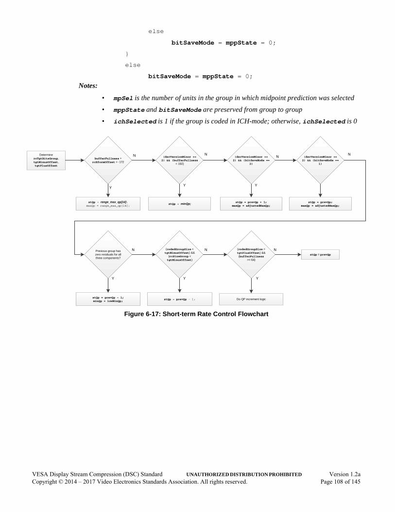
else
bitSaveMode = mppState = 0;
}
else
bitSaveMode = mppState = 0;
Notes:
• mpSel is the number of units in the group in which midpoint prediction was selected
• mppState and bitSaveMode are preserved from group to group
• ichSelected is 1 if the group is coded in ICH-mode; otherwise, ichSelected is 0
Figure 6-17: Short-term Rate Control Flowchart
Determine rcTgtBitsGroup, tgtMinusOffset, tgtPlusOffset
(codedGroupSize < tgtMinusOffset) &&
(rcSizeGroup < tgtMinusOffset)
stQp = prevQp - 1;
(codedGroupSize > tgtPlusOffset) &&(bufferFullness
>= 64)
stQp = prevQp
Do QP increment logic
Previous group has zero residuals for all three components?
stQp = prevQp - 1;minQp = lowMinQp;
bufferFullness + rcXformOffset > -172
stQp = range_max_qp[14];maxQp = range_max_qp[14];
(dscVersionMinor == 2) && (bufferFullness
< 192)
stQp = minQp;
(dscVersionMinor == 2) && (bitSaveMode ==
2)
stQp = prevQp + 1;maxQp = adjustedMaxQp;
N
YY
N
Y
N
Y
N
Y
N
Y
N
(dscVersionMinor == 2) && (bitSaveMode ==
1)
stQp = prevQp;maxQp = adjustedMaxQp;
N
VESA Display Stream Compression (DSC) Standard UNAUTHORIZED DISTRIBUTION PROHIBITED Version 1.2aCopyright © 2014 – 2017 Video Electronics Standards Association. All rights reserved. Page 108 of 145
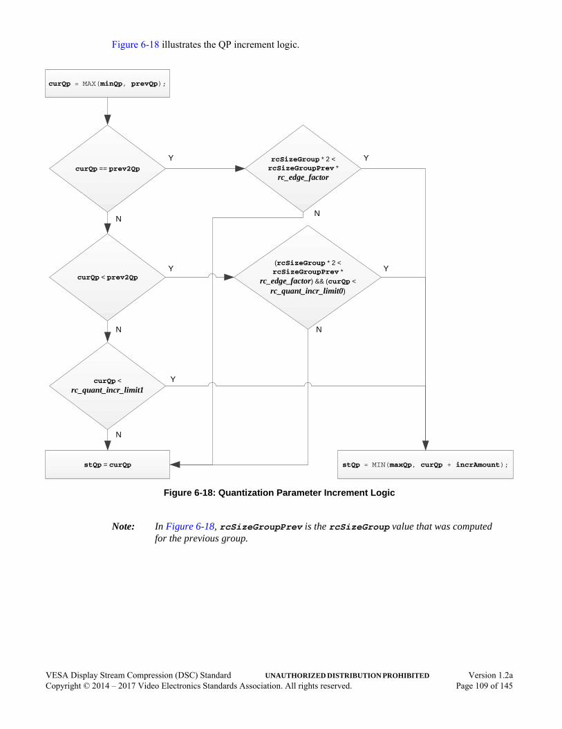
Figure 6-18 illustrates the QP increment logic.
Figure 6-18: Quantization Parameter Increment Logic
Note: In Figure 6-18, rcSizeGroupPrev is the rcSizeGroup value that was computed for the previous group.
stQp = MIN(maxQp, curQp + incrAmount);
curQp = MAX(minQp, prevQp);
rcSizeGroup * 2 <rcSizeGroupPrev *
rc_edge_factorcurQp == prev2Qp
curQp < prev2Qp
stQp = curQp
(rcSizeGroup * 2 <rcSizeGroupPrev *
rc_edge_factor) && (curQp <
rc_quant_incr_limit0)
curQp <
rc_quant_incr_limit1
Y Y
NN
N
N
Y Y
Y
N
VESA Display Stream Compression (DSC) Standard UNAUTHORIZED DISTRIBUTION PROHIBITED Version 1.2aCopyright © 2014 – 2017 Video Electronics Standards Association. All rights reserved. Page 109 of 145

The rcXformBpgOffset value is an offset that is typically positive for the first line within each slice (and second line if Native 4:2:0 mode is used) and negative for all other lines within the slice. The value is internally calculated, as follows:
if (first line of slice)
rcXformBpgOffset = first_line_bpg_offset;else
rcXformBpgOffset = -floor(nfl_bpg_offset);if (second line of slice)
rcXformBpgOffset = second_line_bpg_offset;else
rcXformBpgOffset = -floor(nsl_bpg_offset);rcXformBpgOffset -= floor(slice_bpg_offset);
The target number of bits for each group is referred to as “rcTgtBitsGroup”:
rcTgtBitsGroup = round(pixelsInGroup * bits_per_pixel) + bpgOffset + rcXformBpgOffset;
In addition to responding to rcModelFullness, the RC algorithm adjusts the QP according to a measure of the image’s activity (i.e., how complex the content is to code), using values from the entropy coding – rcSizeGroup and codedGroupSize – which are rough measures of the activity of the group preceding the current group. Large rcSizeGroup and/or codedGroupSize values indicate that the group was difficult to code.
The RC algorithm calculates high and low bits, per group thresholds:
tgtMinusOffset = rcTgtBitsGroup - rc_tgt_offset_lo;
tgtPlusOffset = rcTgtBitsGroup + rc_tgt_offset_hi;
The codedGroupSize and rcSizeGroup values are compared to tgtMinusOffset and tgtPlusOffset to determine whether the image’s activity is within, less than, or greater than the expected range. The rcSizeGroup value is also compared to the constant, 3, which represents the minimum possible number of bits per group. Based on these comparisons, the RC algorithm increases or decreases the QP or leaves the QP unchanged, subject to the minimum and maximum QP boundaries that apply to each range.
If bufferFullness + rcXformOffset is greater than -172 (-224 in Native 4:2:2 mode), the QP is automatically set to range_max_qp for range 14 to avoid overflowing the buffer. Figure 6-18 includes three other PPS parameters:
• rc_edge_factor• rc_quant_incr_limit0• rc_quant_incr_limit1
VESA Display Stream Compression (DSC) Standard UNAUTHORIZED DISTRIBUTION PROHIBITED Version 1.2aCopyright © 2014 – 2017 Video Electronics Standards Association. All rights reserved. Page 110 of 145
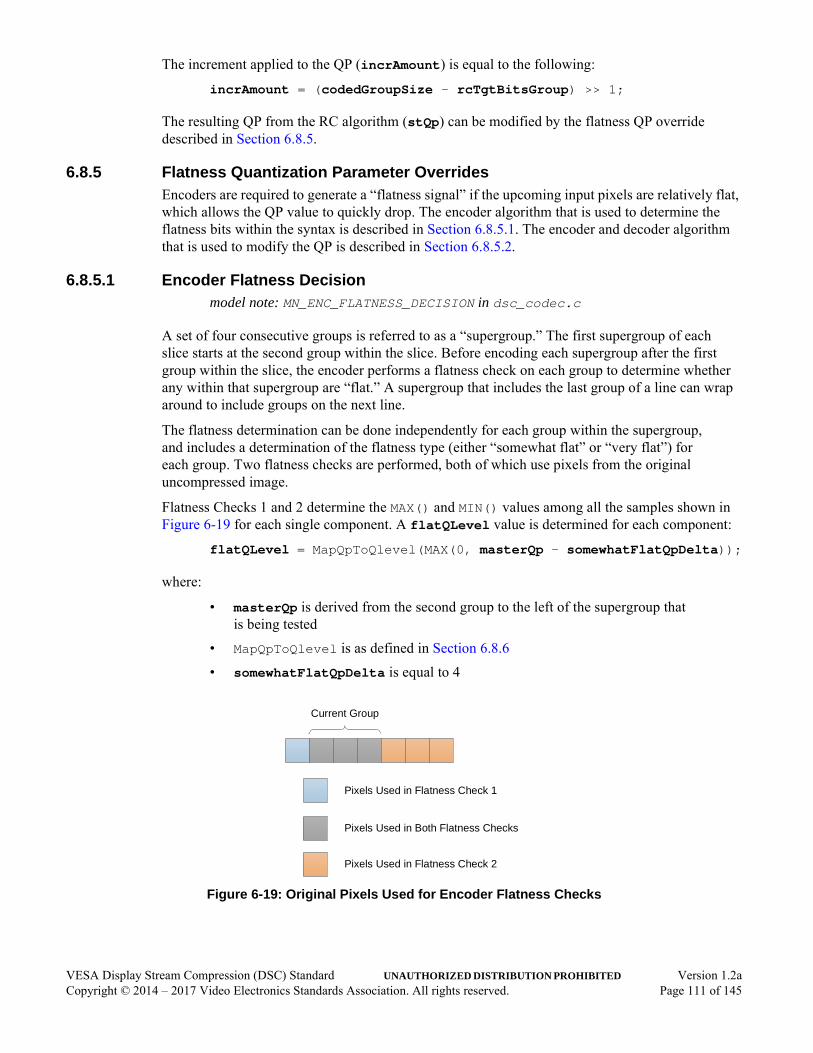
The increment applied to the QP (incrAmount) is equal to the following:
incrAmount = (codedGroupSize - rcTgtBitsGroup) >> 1;
The resulting QP from the RC algorithm (stQp) can be modified by the flatness QP override described in Section 6.8.5.
6.8.5 Flatness Quantization Parameter OverridesEncoders are required to generate a “flatness signal” if the upcoming input pixels are relatively flat, which allows the QP value to quickly drop. The encoder algorithm that is used to determine the flatness bits within the syntax is described in Section 6.8.5.1. The encoder and decoder algorithm that is used to modify the QP is described in Section 6.8.5.2.
6.8.5.1 Encoder Flatness Decisionmodel note: MN_ENC_FLATNESS_DECISION in dsc_codec.c
A set of four consecutive groups is referred to as a “supergroup.” The first supergroup of each slice starts at the second group within the slice. Before encoding each supergroup after the first group within the slice, the encoder performs a flatness check on each group to determine whether any within that supergroup are “flat.” A supergroup that includes the last group of a line can wrap around to include groups on the next line.
The flatness determination can be done independently for each group within the supergroup, and includes a determination of the flatness type (either “somewhat flat” or “very flat”) for each group. Two flatness checks are performed, both of which use pixels from the original uncompressed image.
Flatness Checks 1 and 2 determine the MAX() and MIN() values among all the samples shown in Figure 6-19 for each single component. A flatQLevel value is determined for each component:
flatQLevel = MapQpToQlevel(MAX(0, masterQp - somewhatFlatQpDelta));
where:
• masterQp is derived from the second group to the left of the supergroup that is being tested
• MapQpToQlevel is as defined in Section 6.8.6
• somewhatFlatQpDelta is equal to 4
Figure 6-19: Original Pixels Used for Encoder Flatness Checks
Pixels Used in Flatness Check 1
Pixels Used in Flatness Check 2
Pixels Used in Both Flatness Checks
Current Group
VESA Display Stream Compression (DSC) Standard UNAUTHORIZED DISTRIBUTION PROHIBITED Version 1.2aCopyright © 2014 – 2017 Video Electronics Standards Association. All rights reserved. Page 111 of 145
The flatness checks for Native 4:2:2 and 4:2:0 modes are the same as in 4:4:4 mode, except that flatness checks are performed on the container pixels. Therefore, each pixel in the figure represents a pixel pair in the original image, and even- and odd-position luma samples are treated as independent components.
If the MAX() minus MIN() value for any component is greater than flatnessDetThresh, Flatness Check 1’s check for “very flat” fails; otherwise, the check passes. The value of flatnessDetThresh is equal to (2 << (bits_per_component - 8). If the MAX() minus MIN() value for any component is greater than MAX(flatnessDetThresh, QuantDivisor[flatQLevel]), Flatness Check 1’s check for “somewhat flat” fails; otherwise, the check passes.
If Flatness Check 1 indicates that the group is either “somewhat flat” or “very flat,” that result is the group’s final result. If the “somewhat flat” and “very flat” checks both fail, Flatness Check 2 is performed over the pixels indicated in Figure 6-19. The same comparisons are done as in Flatness Check 1, except that the MAX() and MIN() values are computed over six samples rather than four. The final Flatness Check 2 result is then used as the group’s final result unless the group contains a single pixel (i.e., at the end of a line). In that case, Flatness Check 2 is ignored, and the result of Flatness Check 1 is used as the group’s final result.
For a given supergroup, there are then four flatness indications (one for each group within the supergroup) of either not flat, “somewhat flat,” or “very flat.” The prevIsFlat value is set to 1 if the previous supergroup had a flatness indication; otherwise, the value is cleared to 0. The following algorithm is used to distill the flatness information into a single flatness location and type:
Loop over four groups in supergroup {
If (!prevIsFlat && groupIsFlat)
…// Current group and flatness type is signaled
prevIsFlat = groupIsFlat;
}
where:
• groupIsFlat is true only when the current group is detected as “somewhat flat” or “very flat”
If no group is selected, the QP is not adjusted and the next_flatness_flag that applies to the supergroup is cleared to 0 in the entropy decoder. If a group is selected, the next_flatness_flag that applies to the supergroup is set to 1 and the corresponding group is signaled as the next_flatness_group group within the bitstream, along with its associated next_flatness_type. The entropy encoder signals next_flatness_flag only if the masterQp value is within the flatness_min_qp and flatness_max_qp range; therefore, no adjustment is made in the RC algorithm if the corresponding masterQp is out of range.
Encoder flatness searches do not span to the next line. If a group within a supergroup falls within the next line, that group is not considered to be flat. However, the first group of a line can contain the next_flatness_flag syntax element if the syntax allows the element at that point (see Section 4.5).
VESA Display Stream Compression (DSC) Standard UNAUTHORIZED DISTRIBUTION PROHIBITED Version 1.2aCopyright © 2014 – 2017 Video Electronics Standards Association. All rights reserved. Page 112 of 145
6.8.5.2 Encoder and Decoder Flatness QP Adjustmentmodel note: MN_FLAT_QP_ADJ in dsc_codec.c
The encoder and decoder make the same QP adjustment to a group in which flatness is indicated. The RC algorithm receives a flatness signal corresponding to a particular group within a supergroup that is either “somewhat flat” or “very flat.” When the following conditions exist:
• dsc_version_minor is programmed to 0x2, and
• Current masterQp value is less than the range_max_qp value for rc_range_parameters[14],
the masterQp of the first group of each line, other than the first line, is adjusted using the “very flat” adjustment described below; however, the group is never signaled as such because flatness searches do not span lines.
Note: If the current masterQp value is less than somewhatFlatQpThresh (which is equal to 7 + (2 * (bits_per_component - 8)), the flatness indication, if there is one, is always “somewhat flat.”
If there is no flatness signal for a particular group, or if the current masterQp value is equal to the range_max_qp value for rc_range_parameters[14], the QP is adjusted as follows:
masterQp = stQp;
For a “somewhat flat” signal, the QP is adjusted as follows:
masterQp = MAX(stQp - somewhatFlatQpDelta, 0);
where:
• somewhatFlatQpDelta is equal to 4
For a “very flat” signal, the QP is adjusted as follows:
masterQp = veryFlatQp
where:
• veryFlatQp is equal to 1 + (2 * (bits_per_component - 8))
If the flatness QP override modifies the masterQp, the modified masterQp is used as the starting point for the short-term RC on the next RC cycle.
6.8.6 Mapping QP to qLevelmodel note: MN_MAP_QP_TO_QLEVEL in dsc_codec.c
If convert_rgb is set to 1 or dsc_version_minor is programmed to 0x1, masterQp is mapped to luma and chroma qLevelY and qLevelC, respectively, according to Table 6-2. If the bit depth for luma and chroma are the same and dsc_version_minor is programmed to 0x2, masterQp is mapped to luma qLevelY using Table 6-2, and chroma qLevelC from the table is further modified using the following equation:
qLevelC = MAX(0, qLevelC - 1);
VESA Display Stream Compression (DSC) Standard UNAUTHORIZED DISTRIBUTION PROHIBITED Version 1.2aCopyright © 2014 – 2017 Video Electronics Standards Association. All rights reserved. Page 113 of 145
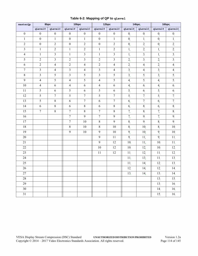
Table 6-2: Mapping of QP to qLevel
masterQp 8bpc 10bpc 12bpc 14bpc 16bpc
qLevelY qLevelC qLevelY qLevelC qLevelY qLevelC qLevelY qLevelC qLevelY qLevelC
0 0 0 0 0 0 0 0 0 0 0
1 0 1 0 1 0 1 0 1 0 1
2 0 2 0 2 0 2 0 2 0 2
3 1 2 1 2 1 2 1 2 1 2
4 1 3 1 3 1 3 1 3 1 3
5 2 3 2 3 2 3 2 3 2 3
6 2 4 2 4 2 4 2 4 2 4
7 3 4 3 4 3 4 3 4 3 4
8 3 5 3 5 3 5 3 5 3 5
9 4 5 4 5 4 5 4 5 4 5
10 4 6 4 6 4 6 4 6 4 6
11 5 6 5 6 5 6 5 6 5 6
12 5 7 5 7 5 7 5 7 5 7
13 5 8 6 7 6 7 6 7 6 7
14 6 8 6 8 6 8 6 8 6 8
15 7 8 7 8 7 8 7 8 7 8
16 7 9 7 9 7 9 7 9
17 7 10 8 9 8 9 8 9
18 8 10 8 10 8 10 8 10
19 9 10 9 10 9 10 9 10
20 9 11 9 11 9 11
21 9 12 10 11 10 11
22 10 12 10 12 10 12
23 11 12 11 12 11 12
24 11 13 11 13
25 11 14 12 13
26 12 14 12 14
27 13 14 13 14
28 13 15
29 13 16
30 14 16
31 15 16
VESA Display Stream Compression (DSC) Standard UNAUTHORIZED DISTRIBUTION PROHIBITED Version 1.2aCopyright © 2014 – 2017 Video Electronics Standards Association. All rights reserved. Page 114 of 145

7 Decoding Process (Normative)This section describes the processing required for DSC-compatible decoders. If there are discrepancies between this document and the C model, the C model implementation shall take precedence. References to the C model are provided below the section headers, as appropriate.
7.1 Substream DemultiplexingSlices are demultiplexed into the three or four component-wise substreams to perform the entropy decoding. The demultiplexer is illustrated in Figure 7-1.
Figure 7-1: Substream Demultiplexing Block Diagram
The demultiplexer receives requests from each SSP that indicates that a mux word is needed. The request signal is sent if the current funnel shifter fullness minus the decoded syntax element size is less than the maximum syntax element size. Zero, one, two, three, or four requests can occur for any given group time. If multiple requests are asserted within a given group time, the order of the mux words within a slice is muxWordY, followed by muxWordCo, followed by muxWordCg, followed by muxWordY2.
If vbr_enable is cleared to 0 (constant bit rate (CBR) mode), the demultiplexer shall flush any stuffed “0” padding bits from the end of a slice (that were inserted by the encoder to pad the slice) to a total compressed size of chunk_size * slice_height bytes.
If vbr_enable is set to 1 (variable bit rate (VBR) mode), no stuffed “0” padding bits are removed from the end of the slice.
Demultiplexer
Rate Buffer
Funnel Shifter
Funnel Shifter
Funnel Shifter
Entropy Decoder Y
Entropy Decoder Co
Entropy Decoder Cg
Rate Control
muxWordY
requestY
muxWordCo
requestCo
muxWordCg
requestCg
Up to 4 mux words
Funnel Shifter Entropy Decoder Y2
muxWordY2
requestY2
VESA Display Stream Compression (DSC) Standard UNAUTHORIZED DISTRIBUTION PROHIBITED Version 1.2aCopyright © 2014 – 2017 Video Electronics Standards Association. All rights reserved. Page 115 of 145
7.2 Entropy Decodingmodel note: MN_DEC_ENTROPY in dsc_codec.c
The entropy decoder parses the bits from the incoming bitstream after demultiplexing. The Picture Layer is demultiplexed to extract the Slice Layer bits for each slice. The substream demultiplexer demultiplexes the Slice Layer data into three or four substreams. The entropy decoder parses the Substream Layer, which is described in Section 4.5.
Each group in the Substream Layer is sequentially processed. Some groups have conditional bits at the beginning of the luma unit, associated with flatness determination. After each group is processed, the entropy decoder sends the residual and ICH index data to the pixel reconstruction and ICH blocks. The entropy decoder outputs the total number of bits parsed for the entire group (codedGroupSize) and number of bits that would have been used had the sizes been optimally predicted (rcSizeGroup) to the rate control.
After each group is processed, the resulting residuals and ICH selections are passed to the pixel reconstruction and ICH blocks.
Each line is required to start on a group boundary. If the slice_width is not evenly divisible by the group size, the last group of each line represents fewer than a group’s worth of pixels. However, the entropy decoder still parses three residuals in P-mode and three history indices in ICH-mode. Although no pixel data is produced for pixels beyond the edge of the slice, the P-mode residuals are still used for the purposes of calculating the next predicted size.
If the input rate buffer overflows, the decoder shall treat the overflow as an error condition. The decoder counts the bits as the bits are decoded, and flags an error condition if the entropy decoder attempts to parse bits beyond the end of the slice data. The slice data length is either fixed (vbr_enable is cleared to 0; CBR mode) or is variable and communicated to the decoder by the transport (vbr_enable is set to 1; VBR mode). See Section 7.8 for decoder error handling requirements.
7.3 Rate ControlThe main rate control (RC) algorithm in the decoder is the same as that in the encoder. For interoperability, the encoder and decoder RC must produce the same QP values at every group. (See Section 6.8 for the encoder specification.)
For each group, where the encoder encodes the group and adds the number of bits used to code the group to its buffer model fullness, the decoder adds the same number of bits to its buffer model fullness when it decodes the group. Both the encoder and decoder RC algorithms subtract the same number of bits when encoding or decoding the same group.
The decoder RC buffer model is the same as the encoder RC buffer model. However, the operating context of a decoder is different from that of an encoder. The decoder has a rate buffer, which is not the same as the RC buffer model.
A bitstream (minus the PPS) to be decoded enters the decoder rate buffer, after which the decoder removes bits from the rate buffer as the bits are decoded. This is opposite to the way in which the RC buffer model operates. At the start of each slice, the decoder accumulates bits within its rate buffer for initial_dec_delay group times before starting to decode the slice. After decoding begins, the RC algorithm behaves the same as in the encoder, including the function of initial_xmit_delay.
VESA Display Stream Compression (DSC) Standard UNAUTHORIZED DISTRIBUTION PROHIBITED Version 1.2aCopyright © 2014 – 2017 Video Electronics Standards Association. All rights reserved. Page 116 of 145
Flatness information is conveyed to the decoder RC by way of the entropy decoder. The flatness information for a given supergroup is signaled in the previous supergroup to simplify entropy decoding and timing. If the flatnessFlag is cleared to 0 for a given supergroup, no QP adjustment is made. If the flatnessFlag is set to 1 for a given supergroup:
• flatnessGroup signals which of the four groups within the supergroup requires the QP adjustment
• flatnessType indicates whether the content is “somewhat flat” or “very flat”
If the flatnessType is not explicitly signaled within the bitstream because the QP is too low, the flatnessType is 0 (“somewhat flat”). The QP adjustment is done in exactly the same manner as the encoder, as specified in Section 6.8.5.2.
7.4 Line Storagemodel note: MN_LINE_STORAGE in dsc_codec.c
DSC requires a single line storage to access pixels from the previous line. By default, the decoder line buffer stores full range reconstructed samples. However, decoders can choose to use a line buffer with a smaller bit depth to minimize implementation costs. If a smaller bit depth is used, the decoder must communicate this to the encoder, using a mechanism that is not defined in this Standard (see Section 5). The encoder shall set its linebuf_depth according to what the decoder implementation supports. The following method for bit-reducing samples shall be used:
shiftAmount = MAX(0, cpntBitDepth - linebuf_depth);round = (shiftAmount > 0) ? (1 << (shiftAmount - 1)) : 0;
storedSample = (sample + round) >> shiftAmount;
readSample = storedSample << shiftAmount;
where:
• cpntBitDepth is the number of bits used to represent the current component’s bit depth
• storedSample is the sample value that is written to the line buffer
• readSample is the value that is read back
VESA Display Stream Compression (DSC) Standard UNAUTHORIZED DISTRIBUTION PROHIBITED Version 1.2aCopyright © 2014 – 2017 Video Electronics Standards Association. All rights reserved. Page 117 of 145

7.5 Prediction and ReconstructionThe prediction and reconstruction functions in the decoder shall match the corresponding encoder functions.
7.5.1 Prediction MethodsThe decoder uses the same prediction methods as those specified for the encoder in Section 6.4 – Modified Median-Adaptive Prediction, Block Prediction, and Midpoint Prediction (MMAP, BP, and MPP, respectively).
7.5.2 Prediction Method SelectionThe bitstream does not explicitly signal the BP vs. MMAP predictor method; therefore, the encoder and decoder shall both follow identical processes to determine which prediction method to use for each group. If a decoder supports BP, the decoder is required to have logic to select between BP and MMAP. If a decoder does not support BP or block_pred_enable is cleared to 0 in the current PPS, BP is never selected and MMAP is used. If the decoder does not support BP and block_pred_enable is set to 1 in the current PPS, the stream is not decodable and the decoder shall handle the error in an appropriate manner.
7.5.2.1 Selection between Block and Modified Median-Adaptive PredictionEncoders and decoders shall perform the same algorithm detailed in Section 6.4.4.1 to select between BP and MMAP.
7.5.2.2 Selection between Block/Modified Median-Adaptive and Midpoint Predictionmodel note: MN_DEC_MPP_SELECT in dsc_codec.c
Note: In the following, the outcome of the BP vs. MMAP decision for the current group (described in Section 7.5.2.1) is referred to as “BP/MMAP.”
The selection between BP/MMAP and MPP is signaled in the bitstream. The size used for delta size unit-variable length coding (DSU-VLC) determines whether the decoder uses MPP or BP/MMAP. If the size is equal to the cpntBitDepth - qLevel for some unit, the samples are predicted using MPP for that unit. Otherwise, BP or MMAP is used to predict the three samples coded by that unit.
VESA Display Stream Compression (DSC) Standard UNAUTHORIZED DISTRIBUTION PROHIBITED Version 1.2aCopyright © 2014 – 2017 Video Electronics Standards Association. All rights reserved. Page 118 of 145

7.6 Indexed Color HistoryThe decoder is required to have the same mapping of Indexed Color History (ICH) values to pixels as an encoder for every group. Figure 7-2 illustrates how the ICH works in a decoder.
Figure 7-2: Indexed Color History in Decoder
7.6.1 HistoryThe decoder history structure is the same as the encoder history structure. Section 6.5 specifies the details of ICH operation. The decoding process for updating the ICH is identical to the encoding process for updating the ICH, as specified in Section 6.5.1 and Section 6.5.2.
7.6.2 Decoder History UpdatesFor each group, the entropy coding indicates whether ICH-mode is selected. If ICH-mode is selected, the history indices are provided by the entropy decoder. Both the encoder and decoder maintain identical ICH states; therefore, the decoder history update process follows the same algorithm described in Section 6.5.2.
ICH32 Entries
(Shift Register)
History Update
P-modePixel Value
OutputPixel Value
Select Entry
From Entropy Decoding
Neighboring Pixels from Previous Line
Set Selected Value to MRU
VESA Display Stream Compression (DSC) Standard UNAUTHORIZED DISTRIBUTION PROHIBITED Version 1.2aCopyright © 2014 – 2017 Video Electronics Standards Association. All rights reserved. Page 119 of 145
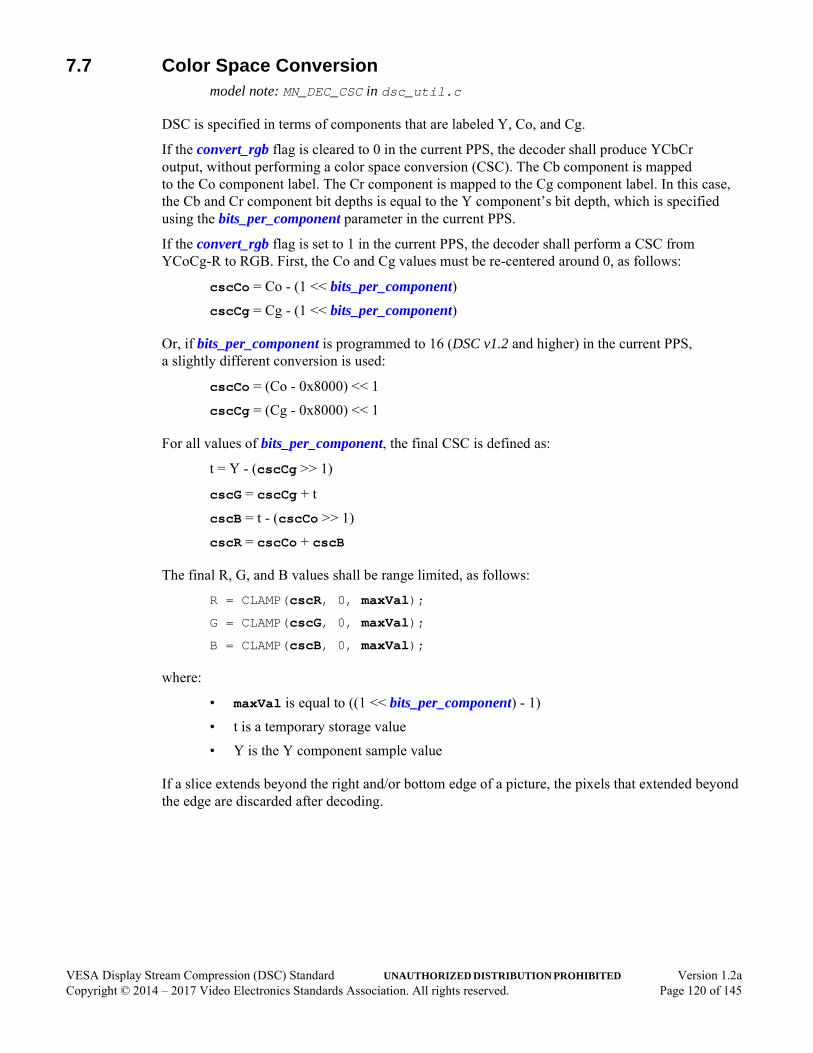
7.7 Color Space Conversionmodel note: MN_DEC_CSC in dsc_util.c
DSC is specified in terms of components that are labeled Y, Co, and Cg.
If the convert_rgb flag is cleared to 0 in the current PPS, the decoder shall produce YCbCr output, without performing a color space conversion (CSC). The Cb component is mapped to the Co component label. The Cr component is mapped to the Cg component label. In this case, the Cb and Cr component bit depths is equal to the Y component’s bit depth, which is specified using the bits_per_component parameter in the current PPS.
If the convert_rgb flag is set to 1 in the current PPS, the decoder shall perform a CSC from YCoCg-R to RGB. First, the Co and Cg values must be re-centered around 0, as follows:
cscCo = Co - (1 << bits_per_component)cscCg = Cg - (1 << bits_per_component)
Or, if bits_per_component is programmed to 16 (DSC v1.2 and higher) in the current PPS, a slightly different conversion is used:
cscCo = (Co - 0x8000) << 1
cscCg = (Cg - 0x8000) << 1
For all values of bits_per_component, the final CSC is defined as:
t = Y - (cscCg >> 1)
cscG = cscCg + t
cscB = t - (cscCo >> 1)
cscR = cscCo + cscB
The final R, G, and B values shall be range limited, as follows:
R = CLAMP(cscR, 0, maxVal);
G = CLAMP(cscG, 0, maxVal);
B = CLAMP(cscB, 0, maxVal);
where:
• maxVal is equal to ((1 << bits_per_component) - 1)
• t is a temporary storage value
• Y is the Y component sample value
If a slice extends beyond the right and/or bottom edge of a picture, the pixels that extended beyond the edge are discarded after decoding.
VESA Display Stream Compression (DSC) Standard UNAUTHORIZED DISTRIBUTION PROHIBITED Version 1.2aCopyright © 2014 – 2017 Video Electronics Standards Association. All rights reserved. Page 120 of 145

7.8 Error HandlingIf an error condition is detected, the decoder is required to output pixel data until the end of the slice; however, this Standard does not define what the pixel data must be. The decoder shall discard the current slice’s compressed bits from the rate buffer (if any of the slice’s bits are still in the buffer), then resume decoding, starting with the next slice. Occurrence of an error within a slice shall not affect decoding of any other slice.
VESA Display Stream Compression (DSC) Standard UNAUTHORIZED DISTRIBUTION PROHIBITED Version 1.2aCopyright © 2014 – 2017 Video Electronics Standards Association. All rights reserved. Page 121 of 145
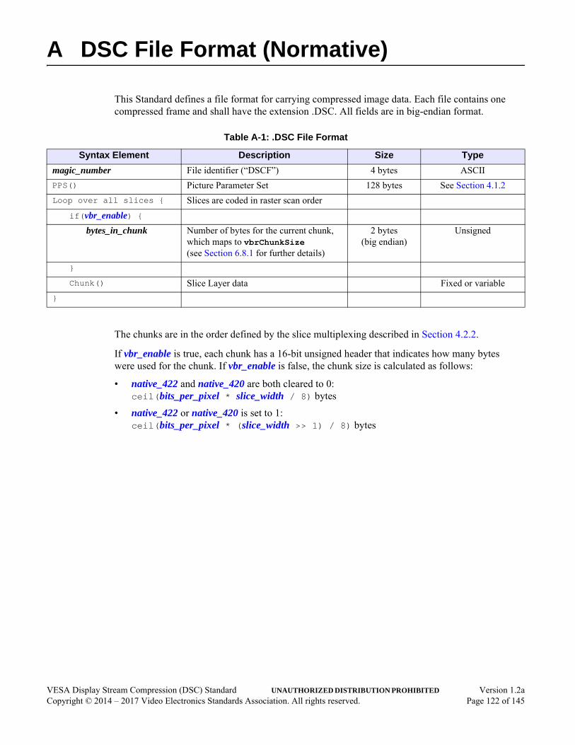
VESA Display Stream Compression (DSC) Standard UNAUTHORIZED DISTRIBUTION PROHIBITED Version 1.2aCopyright © 2014 – 2017 Video Electronics Standards Association. All rights reserved. Page 122 of 145
A DSC File Format (Normative)
This Standard defines a file format for carrying compressed image data. Each file contains one compressed frame and shall have the extension .DSC. All fields are in big-endian format.
The chunks are in the order defined by the slice multiplexing described in Section 4.2.2.
If vbr_enable is true, each chunk has a 16-bit unsigned header that indicates how many bytes were used for the chunk. If vbr_enable is false, the chunk size is calculated as follows:
• native_422 and native_420 are both cleared to 0: ceil(bits_per_pixel * slice_width / 8) bytes
• native_422 or native_420 is set to 1: ceil(bits_per_pixel * (slice_width >> 1) / 8) bytes
Table A-1: .DSC File Format
Syntax Element Description Size Type
magic_number File identifier (“DSCF”) 4 bytes ASCII
PPS() Picture Parameter Set 128 bytes See Section 4.1.2
Loop over all slices { Slices are coded in raster scan order
if(vbr_enable) {bytes_in_chunk Number of bytes for the current chunk,
which maps to vbrChunkSize (see Section 6.8.1 for further details)
2 bytes (big endian)
Unsigned
}
Chunk() Slice Layer data Fixed or variable
}

B Simple 4:2:2 Mode (Informative)
model note: MN_SIMPLE_422_444 and MN_SIMPLE_444_422 in dsc_util.c
Some applications that support both 4:4:4 and 4:2:2 formats require visually lossless performance at the same bit rate and throughput, regardless of the subsampling mode. In these applications, Native 4:2:2 mode may introduce unneeded complexity. This annex describes an optional, simple way to code 4:2:2 source video with visually lossless quality at the same supported bit/pixel rates as 4:4:4 mode. This annex describes an easy method that can be referenced by an application specification to convert 4:2:2 to 4:4:4 that can be coded with DSC. This annex also describes how to convert decoded 4:4:4 pixels back into 4:2:2 output. The simple_422 PPS parameter indicates for the decoder use the 4:4:4 to 4:2:2 sample-dropping method described below.
Figure B-1 illustrates the system view with 4:2:2 input/output.
Figure B-1: System with 4:2:2 Input/Output
To convert from 4:2:2 to 4:4:4, each missing chroma sample is interpolated using the average of the chroma values of the same component from the two immediate left and right surrounding pixels, as illustrated in Figure B-2.
Figure B-2: Simple 4:2:2 to 4:4:4 Conversion at Encoder Input
DSC Encoder DSC DecoderConvert
4:2:2 to 4:4:4Convert
4:4:4 to 4:2:2
4:2:2 Input 4:2:2 OutputLink
Luma sample
Chroma sample
0.5 0.5 0.5 0.5
…
…
…
…
VESA Display Stream Compression (DSC) Standard UNAUTHORIZED DISTRIBUTION PROHIBITED Version 1.2aCopyright © 2014 – 2017 Video Electronics Standards Association. All rights reserved. Page 123 of 145

The resulting 4:4:4 is encoded using the DSC algorithm at the encoder, and 4:4:4 is decoded using the DSC algorithm at the decoder. The decoded 4:4:4 video is converted back to 4:2:2 by dropping the chroma from every other pixel, as illustrated in Figure B-3.
Figure B-3: 4:4:4 to Simple 4:2:2 Conversion at Decoder Output
Luma sample
Chroma sample
Drop Drop
…
…
…
…
VESA Display Stream Compression (DSC) Standard UNAUTHORIZED DISTRIBUTION PROHIBITED Version 1.2aCopyright © 2014 – 2017 Video Electronics Standards Association. All rights reserved. Page 124 of 145

C Guidance for Mapping to Transport (Informative)
This annex provides guidance to application specification committees to assist in using DSC within such specifications.
• The DSC algorithm is specified such that the unit of time is a pixel time. A pixel time is the same as the input to an encoder, output of an encoder, input to a decoder, and output of a decoder. Hence, time can be treated by this Standard algorithmically, without reliance on any specific real time or clocking assumptions. Different methods are possible for dealing with the horizontal blanking time. In most real-world applications, there is a horizontal blanking period (HBlank) at the display, as well as in the transport timing (i.e., time each line (in the transport) when there are no DSC bits conveyed). The display HBlank and transport HBlank can be the same or different. These HBlank values, among other things, generally determine an amount of additional bitstream buffering and delay that is needed in DSC Sink devices (i.e., either the Transport Layer (which is outside the scope of this Standard) or decoder), and an additional amount of bitstream buffer that is needed in DSC Source devices.
• There is a difference between the physical rate buffer size and rate buffer size that is specified in DSC. The former is a function of implementation, and the latter is the size of a buffer model within the compression algorithm. Care should be taken in application specifications to distinguish between these two sizes.
• DSC requires that all lines start on a group boundary. A fractional amount of additional throughput might be required at the right edges of slices because in some usages, the slice widths might not be an integer multiple of the group size.
• The DSC algorithm does not provide for error concealment. If a bit error occurs, it is reasonable to assume that the pixel data is corrupted for the remainder of that slice. Therefore, it is important for transport specifications to ensure low bit-error rates to avoid obtrusive artifacts in the output video.
• Variable bit rate (VBR) mode (enabled when vbr_enable is set to 1) can be helpful in cases where it is important to save power by temporarily disabling the display link. The compressed bits can be stored within a frame buffer in the decoder, or VBR mode can be used without a compressed frame buffer. In this case, the maximum data rate needed is constrained; however, the average data rate over a slice might be less than the specified rate, depending on the image content. VBR mode requires that the transport have a means of communicating to the decoder the starting locations of each slice. This can be conveyed in various ways, such as the number of bits used to code each slice.
• In application specifications that allow a screen to be partially updated, it is important to ensure that the compressed bits that correspond to persistent areas within the image are robustly transmitted. It is advisable to include a Cyclic Redundancy Check (CRC) or other error check along with re-transmission in the event of errors, to ensure that incorrect pixel data does not persist on the screen for a long period of time.
• The DSC algorithm does not make any guarantees about degradations due to generation loss. It is advisable to minimize the number of cascaded transcodes that can take place in a display system topology.
VESA Display Stream Compression (DSC) Standard UNAUTHORIZED DISTRIBUTION PROHIBITED Version 1.2aCopyright © 2014 – 2017 Video Electronics Standards Association. All rights reserved. Page 125 of 145

• It is advisable to send PPS data in a robust manner. An error in the PPS data can cause image degradation for every picture to which the erroneous PPS applies.
• Application specifications should consider restricting the number of slices per line for encoders and/or decoders to minimize complexity and ensure interoperability.
• Application specifications can consider restricting the allowed rate control (RC) values to those listed in the RC configuration files supplied with the C model, some of which are also listed in Table E-4 and Table E-5.
• Application specifications should carefully consider interoperability with DSC v1.1 encoders and decoders when referencing DSC v1.2, particularly for modes that are supported by both versions (YCbCr and RGB 4:4:4; 8, 10, and 12 bpc). Specifications may choose to limit dsc_version_minor to be programmed to 0x1 for those modes to promote interoperability with DSC v1.1 implementations. Alternatively, specifications may mandate support for both DSC v1.1 and DSC v1.2 (i.e., dsc_version_minor programmed to 0x1 or 0x2) for some or all of these modes. For YCbCr 4:4:4 modes in particular, the DSC v1.2 updates provide improved quality for certain types of content; therefore, it is recommended that applications that require YCbCr 4:4:4 use the DSC v1.2 modes. Note that DSC v1.1 interoperability for both encoders and decoders is required for any transport that supports DSC v1.1.
• DSC v1.2 supports two different methods for YCbCr 4:2:2 pictures:
• Simple 4:2:2
• Native 4:2:2
Native 4:2:2 mode should be used for cases in which visually lossless performance is required at a lower bpp than 4:4:4 or higher throughput is needed for 4:2:2 pictures.
• Because the pixel per clock throughput of Native 4:2:2 and 4:2:0 modes is approximately double that of 4:4:4 mode, transport specifications may choose to allow Native 4:2:2 and 4:2:0 modes to be used exclusively for the highest resolutions. For example, a transport specification that supports 8Kp60 using 4:4:4 may support 8Kp120 using only Native 4:2:2 and 4:2:0 modes to keep the number of parallel encoders or decoders the same.
• Because application specifications can impose limits on PPS parameters, it is not necessarily the case that a DSC stream can be passed from one transport to another without transcoding. If this system trait is desirable (e.g., to lower the implementation cost of bridging devices), both transports must be designed with a common set of constraints.
VESA Display Stream Compression (DSC) Standard UNAUTHORIZED DISTRIBUTION PROHIBITED Version 1.2aCopyright © 2014 – 2017 Video Electronics Standards Association. All rights reserved. Page 126 of 145

D Guidance for Hardware Implementations (Informative)
This annex provides guidance for hardware implementations of the DSC algorithm.
D.1 ThroughputThe DSC algorithm is expected to be implemented in a variety of silicon process nodes, at various clock speeds. The encoder algorithm is optimized for hardware implementations at 1 pixel/clock (2 pixels/clock for Native 4:2:2 or 4:2:0 mode). The decoder algorithm is optimized for hardware implementations at 3 pixels/clock (6 pixels/clock for Native 4:2:2 or 4:2:0 mode). It is straightforward to design hardware blocks at lower throughput, which can minimize implementation costs.
In cases where additional throughput is needed, the number of slices per line can be increased. For example, using 2 slices/line in conjunction with two decoder instances that support 3 pixels/clock allows for a total throughput of 6 pixels/clock.
Alternatively, a screen image can be partitioned into regions that are coded by separate DSC instances, and the DSC bitstreams for each region carried by separate links. Such an approach enables concurrent operation by the parallel DSC instances, and therefore, greater pixel/clock throughput without the use of multiple slices per line.
In another option, some decoder implementations can decode pixels at the display’s pixel rate and be idle during the display horizontal blanking period (HBlank), while other implementations can decode pixels at a slower rate and use buffering to match the display’s pixel rate. In this case, it is possible for both implementations to be concurrently compatible with the same transport and display specifications. Such aspects of encoder and decoder implementation are outside the scope of transport specifications.
VESA Display Stream Compression (DSC) Standard UNAUTHORIZED DISTRIBUTION PROHIBITED Version 1.2aCopyright © 2014 – 2017 Video Electronics Standards Association. All rights reserved. Page 127 of 145

D.2 Block PredictionBlock prediction (BP) search can be considered to use three blocks of three samples each, the rightmost of which is the current block. Each block is compared from reference samples with vectors from -1 and -3 to -10. The BP vector (bpVector) determined from the BP search is used for all three samples of the current block. The BP search is performed again when the new current sample is three positions to the right of the previous current sample. The current samples at positions 0, -1, and -2 become the samples at positions -3, -4, and -5 at the next search. Similarly, samples at positions -3, -4, and -5 become the samples at positions -6, -7, and -8, and those at -6, -7, and -8 become those at -9, -10, and -11. The Sum of Absolute Differences (SAD) values resulting from comparing one block to reference samples with the candidate vectors (candidateVectors) are the same values as those produced when the search is performed later, when the new current block is three samples to the right of the previous current block. Therefore, implementations can choose to retain and re-use the SAD results corresponding to the nine candidateVectors for each three-sample block. Retaining and re-using the results significantly reduces the amount of search operations performed, as compared to a direct search of all positions for all samples every block. The algorithmic result from any implementation choice is the same as the result from performing a full direct search for all samples every block.
Because the BP search is performed on the line previous to the sample being coded, there is a broad range of times in which the BP search can be performed, all producing the same result. The earliest time the BP search can be performed is the earliest time when all samples are available. The latest time the BP search can be performed is just before the search decision is needed for coding the current sample. Various implementations can make different choices regarding when to perform the BP search.
D.3 Rate Buffer SizeThe required rate buffer size varies as a function of the PPS parameters. Therefore, implementers must choose a rate buffer size that will not overflow or underflow when using the worst-case PPS parameters that are supported by that implementation. The required rate buffer model size for a specific configuration is provided by a formula in Annex E (minRateBufferSize); however, implementations may require a larger or smaller physical buffer than the buffer model due to slice multiplexing, blanking, substream multiplexing, intermediate buffering, or other factors.
VESA Display Stream Compression (DSC) Standard UNAUTHORIZED DISTRIBUTION PROHIBITED Version 1.2aCopyright © 2014 – 2017 Video Electronics Standards Association. All rights reserved. Page 128 of 145

E Derivation of Rate Control Parameters (Informative)
The Picture Parameter Set (PPS) specified in Section 4.1 contains many parameters related to rate control (RC). This annex provides explanation and guidance regarding how to derive these parameters. In addition, the DSC C model (and in particular, codec_main.c) provides formulae for some of the rate RC parameters.
Table E-1 lists intermediate RC parameter values that are useful to compute.
Table E-1: Useful Intermediate Rate Control Parameter Values
Intermediate Parameter Value
Description
pixelsPerGroup Equal to three (3).
groupsPerLine Number of groups used to code each line of a slice.
Equal to ceil(slice_width / pixelsPerGroup) in 4:4:4 mode.
Equal to ceil((slice_width >>1) / pixelsPerGroup) in Native 4:2:2 or 4:2:0 mode.
groupsTotal Number of groups used to code the entire slice. Equal to groupsPerLine * slice_height.hrdDelay Total end-to-end hypothetical reference decoder (HRD) delay, in units of pixel time.
This is equal to ceil(minRateBufferSize / bits_per_pixel).
minRateBufferSize Minimum rate buffer size, in units of bits. The real physical rate buffer must be slightly larger than this to account for subtle differences between the model and hardware group times (e.g., delays can be rounded up to a whole number). For modes other than Native 4:2:2 or 4:2:0, an upper bound on this is rc_model_size - initial_offset + ceil(initial_xmit_delay * bits_per_pixel) + groupsPerLine * first_line_bpg_offset. For Native 4:2:2 and 4:2:0 modes, the C model implements a tighter bound by finding the maximum offset (maxOffset) and setting minRateBufferSize to rc_model_size - initial_offset + maxOffset (see model note MN_MIN_RBS in codec_main.c for details).
numExtraMuxBits Number of bits that can remain at the end of a slice due to substream multiplexing (SSM). A conservative estimate for this is (muxWordSize + maxSeSize_Y - 2) + 2 * (muxWordSize + maxSeSize_C - 2). In Native 4:2:2 mode, four substream processors (SSPs) are used; thus, the estimate becomes (muxWordSize + maxSeSize_Y - 2) + 3 * (muxWordSize + maxSeSize_C - 2). All three or four SSPs could be requesting a mux word at the end of the slice where there is only one bit remaining for each SSP, and every SSP is sending requests during the second-to-last group time (no requests are sent during the last group time because there is nothing to process for the next group). However, if sliceBits - numExtraMuxBits is not a multiple of muxWordSize, numExtraMuxBits can be further reduced until sliceBits - numExtraMuxBits is a multiple of muxWordSize because sending of partial mux words is not allowed.
sliceBits Total number of bits allocated for a slice. Equal to 8 * chunk_size * slice_height.
VESA Display Stream Compression (DSC) Standard UNAUTHORIZED DISTRIBUTION PROHIBITED Version 1.2aCopyright © 2014 – 2017 Video Electronics Standards Association. All rights reserved. Page 129 of 145

Table E-2 lists recommended and required PPS syntax element rate control values.
Table E-2: Recommended and Required PPS Syntax Element Rate Control Values
PPS Syntax Element Recommended and Required Values
first_line_bpg_offset The first line of each slice does not code as efficiently as subsequent lines, due to the lack of vertical prediction and Indexed Color History (ICH) upper neighboring pixels. To maintain uniform visual quality across a slice, it is important to provide an extra bit allocation for the first line. Empirical results have shown that a value of 15bpg works well in general. The first_line_bpg_offset value should be smaller when slice_height is smaller; therefore, it is recommended that first_line_bpg_offset be scaled according to slice_height:• first_line_bpg_offset = 12 + (int) (0.09 * MIN(34, slice_height - 8))
for slice_height ≥ 8
• first_line_bpg_offset = 2 * (slice_height - 1) for slice_height < 8
second_line_bpg_offset The second line of a slice in 4:2:0 mode does not code as efficiently as subsequent lines due to the lack of vertical prediction and ICH upper neighboring pixels. To maintain uniform visual quality across a slice, it is important to provide an extra bit allocation for the second line in 4:2:0 mode. Empirical results have shown that a value of 12bpg works well in general. If slice_height < 8, the recommended second_line_bpg_offset is equal to 2 * (slice_height - 1).
initial_xmit_delay If the initial transmission delay is 0, the buffer level would need to be constrained to a “0” bit at the end of a slice to guarantee that a slice contains the correct number of bits. This could be problematic because it would be difficult to ensure good visual quality at the end of a slice. A non-zero initial_xmit_delay allows a final maximum buffer fullness of up to initial_xmit_delay * bits_per_pixel. Empirical results have shown good performance when initial_xmit_delay * bits_per_pixel ≈ rc_model_size * 0.5.
initial_dec_delay The total HRD delay must be a constant so that the decoder does not wait the same number of pixel times as the encoder before starting the decode. The initial_xmit_delay + initial_dec_delay corresponds with the total HRD delay, in units of pixel time, which is equal to hrdDelay (see Table E-1).
initial_offset The initial offset indicates the initial condition within the RC model. A high initial_offset value means that the rate control quickly reacts at the beginning of a slice. In contrast, a low initial_offset value means that the RC reacts more slowly. Empirical results have shown that a value of 6144 works well at 8bpp, and a value of 2048 works well at 12bpp.
second_line_offset_adj Represents an additional offset that is applied on the second line of a slice in 4:2:0 mode. Added to the RC offset at the beginning of a slice and then subtracted from the first group of the second line of the slice. Intended to help preserve the chroma quality for the second line where there is no vertical prediction. Empirical results have shown that a value of 512 provides good quality.
rc_model_size Indicates the size of the RC model; larger values enhance the ability of the RC to allocate bits across the slice. However, a larger rc_model_size can require a larger physical rate buffer and impact performance on smaller slices. Empirical results have shown an rc_model_size of 8192 bits performs well for slices containing 15000 or more pixels.
VESA Display Stream Compression (DSC) Standard UNAUTHORIZED DISTRIBUTION PROHIBITED Version 1.2aCopyright © 2014 – 2017 Video Electronics Standards Association. All rights reserved. Page 130 of 145
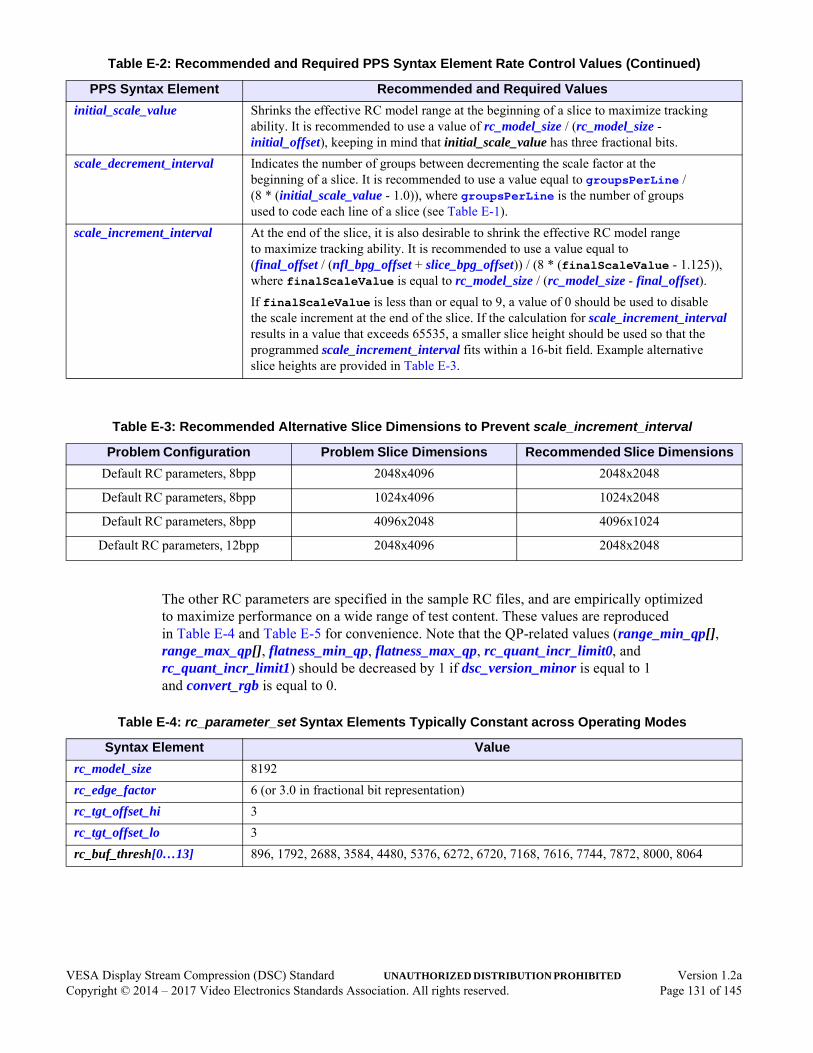
The other RC parameters are specified in the sample RC files, and are empirically optimized to maximize performance on a wide range of test content. These values are reproduced in Table E-4 and Table E-5 for convenience. Note that the QP-related values (range_min_qp[], range_max_qp[], flatness_min_qp, flatness_max_qp, rc_quant_incr_limit0, and rc_quant_incr_limit1) should be decreased by 1 if dsc_version_minor is equal to 1 and convert_rgb is equal to 0.
initial_scale_value Shrinks the effective RC model range at the beginning of a slice to maximize tracking ability. It is recommended to use a value of rc_model_size / (rc_model_size - initial_offset), keeping in mind that initial_scale_value has three fractional bits.
scale_decrement_interval Indicates the number of groups between decrementing the scale factor at the beginning of a slice. It is recommended to use a value equal to groupsPerLine / (8 * (initial_scale_value - 1.0)), where groupsPerLine is the number of groups used to code each line of a slice (see Table E-1).
scale_increment_interval At the end of the slice, it is also desirable to shrink the effective RC model range to maximize tracking ability. It is recommended to use a value equal to (final_offset / (nfl_bpg_offset + slice_bpg_offset)) / (8 * (finalScaleValue - 1.125)), where finalScaleValue is equal to rc_model_size / (rc_model_size - final_offset).If finalScaleValue is less than or equal to 9, a value of 0 should be used to disable the scale increment at the end of the slice. If the calculation for scale_increment_interval results in a value that exceeds 65535, a smaller slice height should be used so that the programmed scale_increment_interval fits within a 16-bit field. Example alternative slice heights are provided in Table E-3.
Table E-3: Recommended Alternative Slice Dimensions to Prevent scale_increment_interval
Problem Configuration Problem Slice Dimensions Recommended Slice Dimensions
Default RC parameters, 8bpp 2048x4096 2048x2048
Default RC parameters, 8bpp 1024x4096 1024x2048
Default RC parameters, 8bpp 4096x2048 4096x1024
Default RC parameters, 12bpp 2048x4096 2048x2048
Table E-4: rc_parameter_set Syntax Elements Typically Constant across Operating Modes
Syntax Element Value
rc_model_size 8192
rc_edge_factor 6 (or 3.0 in fractional bit representation)
rc_tgt_offset_hi 3
rc_tgt_offset_lo 3
rc_buf_thresh[0…13] 896, 1792, 2688, 3584, 4480, 5376, 6272, 6720, 7168, 7616, 7744, 7872, 8000, 8064
Table E-2: Recommended and Required PPS Syntax Element Rate Control Values (Continued)
PPS Syntax Element Recommended and Required Values
VESA Display Stream Compression (DSC) Standard UNAUTHORIZED DISTRIBUTION PROHIBITED Version 1.2aCopyright © 2014 – 2017 Video Electronics Standards Association. All rights reserved. Page 131 of 145

Table E-5: Common Recommended Rate Control-Related Parameter Valuesa
Syntax Elementb At 8bpp/8bpc
At 8bpp/10bpc
At 8bpp/12bpc
At 12bpp/8bpc
At 12bpp/10bpc
At 12bpp/12bpc
initial_xmit_delay 512 512 512 341 341 341
first_line_bpg_offset 15 15 15 15 15 15
initial_offset 6144 6144 6144 2048 2048 2048
flatness_min_qp 3 7 11 3 7 11
flatness_max_qp 12 16 20 12 16 20
rc_quant_incr_limit0 11 15 19 11 15 19
rc_quant_incr_limit1 11 15 19 11 15 19
rc_range_parameters[0] MinQp: 0
MaxQp: 4
Offset: 2
MinQp: 0
MaxQp: 8
Offset: 2
MinQp: 0
MaxQp: 12
Offset: 2
MinQp: 0
MaxQp: 2
Offset: 2
MinQp: 0
MaxQp: 2
Offset: 2
MinQp: 0
MaxQp: 6
Offset: 2
rc_range_parameters[1] MinQp: 0
MaxQp: 4
Offset: 0
MinQp: 4
MaxQp: 8
Offset: 0
MinQp: 4
MaxQp: 12
Offset: 0
MinQp: 0
MaxQp: 4
Offset: 0
MinQp: 2
MaxQp: 5
Offset: 0
MinQp: 4
MaxQp: 9
Offset: 0
rc_range_parameters[2] MinQp: 1
MaxQp: 5
Offset: 0
MinQp: 5
MaxQp: 9
Offset: 0
MinQp: 9
MaxQp: 13
Offset: 0
MinQp: 1
MaxQp: 5
Offset: 0
MinQp: 3
MaxQp: 7
Offset: 0
MinQp: 7
MaxQp: 11
Offset: 0
rc_range_parameters[3] MinQp: 1
MaxQp: 6
Offset: -2
MinQp: 5
MaxQp: 10
Offset: -2
MinQp: 9
MaxQp: 14
Offset: -2
MinQp: 1
MaxQp: 6
Offset: -2
MinQp: 4
MaxQp: 8
Offset: -2
MinQp: 8
MaxQp: 12
Offset: -2
rc_range_parameters[4] MinQp: 3
MaxQp: 7
Offset: -4
MinQp: 7
MaxQp: 11
Offset: -4
MinQp: 11
MaxQp: 15
Offset: -4
MinQp: 3
MaxQp: 7
Offset: -4
MinQp: 6
MaxQp: 9
Offset: -4
MinQp: 10
MaxQp: 13
Offset: -4
rc_range_parameters[5] MinQp: 3
MaxQp: 7
Offset: -6
MinQp: 7
MaxQp: 11
Offset: -6
MinQp: 11
MaxQp: 15
Offset: -6
MinQp: 3
MaxQp: 7
Offset: -6
MinQp: 7
MaxQp: 10
Offset: -6
MinQp: 11
MaxQp: 14
Offset: -6
rc_range_parameters[6] MinQp: 3
MaxQp: 7
Offset: -8
MinQp: 7
MaxQp: 11
Offset: -8
MinQp: 11
MaxQp: 15
Offset: -8
MinQp: 3
MaxQp: 7
Offset: -8
MinQp: 7
MaxQp: 11
Offset: -8
MinQp: 11
MaxQp: 15
Offset: -8
rc_range_parameters[7] MinQp: 3
MaxQp: 8
Offset: -8
MinQp: 7
MaxQp: 12
Offset: -8
MinQp: 11
MaxQp: 16
Offset: -8
MinQp: 3
MaxQp: 8
Offset: -8
MinQp: 7
MaxQp: 12
Offset: -8
MinQp: 11
MaxQp: 16
Offset: -8
rc_range_parameters[8] MinQp: 3
MaxQp: 9
Offset: -8
MinQp: 7
MaxQp: 13
Offset: -8
MinQp: 11
MaxQp: 17
Offset: -8
MinQp: 3
MaxQp: 8
Offset: -8
MinQp: 7
MaxQp: 12
Offset: -8
MinQp: 11
MaxQp: 16
Offset: -8
VESA Display Stream Compression (DSC) Standard UNAUTHORIZED DISTRIBUTION PROHIBITED Version 1.2aCopyright © 2014 – 2017 Video Electronics Standards Association. All rights reserved. Page 132 of 145

rc_range_parameters[9] MinQp: 3
MaxQp: 10
Offset: -10
MinQp: 7
MaxQp: 14
Offset: -10
MinQp: 11
MaxQp: 18
Offset: -10
MinQp: 3
MaxQp: 9
Offset: -10
MinQp: 7
MaxQp: 13
Offset: -10
MinQp: 11
MaxQp: 17
Offset: -10
rc_range_parameters[10] MinQp: 5
MaxQp: 10
Offset: -10
MinQp: 9
MaxQp: 14
Offset: -10
MinQp: 13
MaxQp: 18
Offset: -10
MinQp: 5
MaxQp: 9
Offset: -10
MinQp: 9
MaxQp: 13
Offset: -10
MinQp: 13
MaxQp: 17
Offset: -10
rc_range_parameters[11] MinQp: 5
MaxQp: 11
Offset: -12
MinQp: 9
MaxQp: 15
Offset: -12
MinQp: 13
MaxQp: 19
Offset: -12
MinQp: 5
MaxQp: 9
Offset: -12
MinQp: 9
MaxQp: 13
Offset: -12
MinQp: 13
MaxQp: 17
Offset: -12
rc_range_parameters[12] MinQp: 5
MaxQp: 11
Offset: -12
MinQp: 9
MaxQp: 15
Offset: -12
MinQp: 13
MaxQp: 19
Offset: -12
MinQp: 5
MaxQp: 9
Offset: -12
MinQp: 9
MaxQp: 13
Offset: -12
MinQp: 13
MaxQp: 17
Offset: -12
rc_range_parameters[13] MinQp: 9
MaxQp: 12
Offset: -12
MinQp: 13
MaxQp: 16
Offset: -12
MinQp: 17
MaxQp: 20
Offset: -12
MinQp: 7
MaxQp: 10
Offset: -12
MinQp: 11
MaxQp: 14
Offset: -12
MinQp: 15
MaxQp: 18
Offset: -12
rc_range_parameters[14] MinQp: 12
MaxQp: 13
Offset: -12
MinQp: 16
MaxQp: 17
Offset: -12
MinQp: 20
MaxQp: 21
Offset: -12
MinQp: 10
MaxQp: 11
Offset: -12
MinQp: 14
MaxQp: 15
Offset: -12
MinQp: 18
MaxQp: 19
Offset: -12
a. MinQp, MaxQp, and Offset represent range_min_qp, range_max_qp, and range_bpg_offset, respectively.b. All parameters listed in this table are described in Table 4-1 or Table 4-2.
Table E-5: Common Recommended Rate Control-Related Parameter Valuesa (Continued)
Syntax Elementb At 8bpp/8bpc
At 8bpp/10bpc
At 8bpp/12bpc
At 12bpp/8bpc
At 12bpp/10bpc
At 12bpp/12bpc
VESA Display Stream Compression (DSC) Standard UNAUTHORIZED DISTRIBUTION PROHIBITED Version 1.2aCopyright © 2014 – 2017 Video Electronics Standards Association. All rights reserved. Page 133 of 145

F Hypothetical Reference Decoder (Informative)
This annex presents a hypothetical reference decoder model that could be used to verify stream compliance. Although some details in this annex are specific to the 4:4:4 modes, the same concepts also apply to Native and Simple 4:2:2 mode and Native 4:2:0 mode.
A hypothetical reference decoder (HRD) model is a theoretical buffer model that forms a test that can be applied to bitstreams, and all conforming bitstreams should pass this test. The HRD test can be used to ensure that an encoded video stream can be correctly buffered and played back by a conforming decoder within a correctly functioning real-time system. The HRD is not intended to represent a real system or decoder. This annex should not be interpreted as giving advice regarding how to design real systems and decoders.
Because the DSC encoding process specification is normative and HRD constraints are built into the encoding process design, DSC streams that conform to the encoding process automatically meet HRD constraints. Therefore, it is not necessary to define an HRD conformance test, and hence this annex is informative.
The HRD model defines a schedule, in units of group time, for bits entering and leaving the HRD buffer model. The HRD model ignores the effect of substream multiplexing (SSM).
Note: If SSM were included in the HRD model, the model would need to be slightly more complex, and buffering associated with SSM would need to be included.
Figure F-1 illustrates an example of decoder buffer fullness at different points within a slice.
Figure F-1: Example of Decoder Buffer Fullness at Different Points within Slice
Dec
oder
Buf
fer
Ful
lnes
s
Time
Buffer Size
(3)(2) (4)
Last
Gro
up D
ecod
ed
Initi
al D
eco
der
Del
ay
Bits
Sto
p E
nte
ring
VESA Display Stream Compression (DSC) Standard UNAUTHORIZED DISTRIBUTION PROHIBITED Version 1.2aCopyright © 2014 – 2017 Video Electronics Standards Association. All rights reserved. Page 134 of 145
In constant bit rate (CBR) mode, the HRD schedule is defined as follows:
1 Bits enter the HRD buffer from the start of a slice until the last bit of the slice. A number of bits enter the HRD buffer each group time. This number of bits is equal to (number of pixels in the group) * bits_per_pixel. The number of pixels within the group is three for all groups, except the group time during which the last group of each line of each slice is modeled as being decoded. In this exception case, for purposes of determining the number of bits that enter the HRD buffer, the number of pixels in the group is one or two if the slice width divided by 3 is not an integer. The number of bits that enter each group time is truncated to an integer, and the fractional residual, if any, is retained and added to the number of input bits that apply to the next group time.
2 During the interval associated with initial decoding delay (initial_dec_delay), bits enter but do not leave the HRD buffer. If initial_dec_delay is not an integer number of groups, the decoding delay is rounded up, and up to ceil(2 * bits_per_pixel) bits of additional capacity are required in the decoder buffer.
3 After the initial decoding delay interval and until the end of the slice, at each group time, the HRD model removes the number of bits that code one group, starting with the first group of the slice and continuing, in coding order, through the slice. Bits continue to enter the HRD buffer.
4 After all bits for the slice enter the HRD buffer, no additional bits from the current slice enter the buffer. The decoder continues to decode one group, per group time, removing the number of bits that code each group until the last group is decoded. Any stuffed “0” padding bits that are part of the current slice are flushed from the HRD buffer after the last group is decoded.
5 The HRD buffer neither overflows nor underflows.
In variable bit rate (VBR) mode (enabled when vbr_enable is set to 1), the HRD schedule is similar to that for CBR, except the schedule is modified as follows:
At each group time, if receiving the specified number of bits into the HRD buffer would cause the buffer to overflow, the number of bits that enter the buffer is limited to the largest number that does not cause an overflow; otherwise, the specified number of bits enters the HRD buffer. This decision is performed at each group time.
Note: The above schedule is reasonable to verify compliance of encoded streams; however, this is not a recommendation of how to implement a VBR system.
VESA Display Stream Compression (DSC) Standard UNAUTHORIZED DISTRIBUTION PROHIBITED Version 1.2aCopyright © 2014 – 2017 Video Electronics Standards Association. All rights reserved. Page 135 of 145

G Slice Timing Examples (Informative)
This annex describes and analyzes slice timing use cases.
G.1 Problem StatementThis Standard specifies an algorithm for compression, decompression, and buffering, where the unit of time is a pixel time, which is defined to be consistent for both compressed data and decompressed or uncompressed pixels. The compressed data rate is specified in units of bits per pixel time. The DSC algorithm does not make reference to blanking periods. This implies an idealized bit delivery and decoding schedule that does not have any blanking periods, such that some details of timing and buffering might need to be adapted to practical applications where there generally is a horizontal blanking period (HBlank) within each line. Also, practical designs should consider the effect of decoding multiple slices per line on decoding and display timing, with respect to the data arrival schedule, and how much additional buffer, if any, is required. It is assumed that the HBlank length equally applies to the transport timing and decompressed output video. Uncompressed input to a DSC encoder is not considered when analyzing decoder delay and buffering requirements. The periods of an output scan line and transport line time are assumed to be equal to the L value. The questions to be answered are:
• What is the effect of multiple slices per line on decode timing, display timing, and buffering in the absence of an HBlank?
• What effect does HBlank have on decode and display timing, and how much extra buffering, if any, of compressed data is required to accommodate an HBlank?
There is a similar problem of determining an appropriate amount of delay and buffering in an encoder. This problem is not addressed in this annex. Readers should be able to answer the same questions for an encoder, using a similar approach to that applied here to the decoder.
G.2 AnalysisThe problem and solution are explained using figures that illustrate operation both without and with an HBlank, in cases of 1, 2, and 4 slices/line, and where there is more than 1 slice/line, with both sequential and parallel slice decoding.
By definition, the DSC algorithm is not changed when adapting its use to applications that have a non-zero HBlank and/or multiple slices per line. There are no changes to any aspect of the algorithm, and in particular, no changes to the rate control or buffer model. There can, however, be a need to adapt practical system designs to applications that use an HBlank and/or multiple slices per line.
VESA Display Stream Compression (DSC) Standard UNAUTHORIZED DISTRIBUTION PROHIBITED Version 1.2aCopyright © 2014 – 2017 Video Electronics Standards Association. All rights reserved. Page 136 of 145

G.2.1 Case – 1 Slice/Line
Figure G-1: 1 Slice/Line
Figure G-1 illustrates the general case of 1 slice/line, both without and with an HBlank. Operation is shown starting from the start of a slice at the decoder. The encoding operation is not shown, and the transport delay (i.e., delay from the encoder) is not relevant for this analysis.
In the case of no HBlank, decoding begins after the initial decoding delay, which is specified in units of pixel time. Decoding the end of the first line might require that the last bit be received at the time the last pixel of the line is decoded, with the line length being P pixel times, which spans Lus of time.
In the case of a non-zero HBlank, the same number of P pixel times is compressed into (L - HBlank)us. The pixel rate with HBlank is R2 = P / (L - HBlank)us; R2 > R1. The first transport line’s set of bits is carried at rate R2 in (L - HBlank)us. This is followed by the transport HBlank, when no bits are transported, which is followed by reception of the second transport line’s set of bits. To ensure that the decoder has all the bits needed to be able to decode line 1 on time, the earliest time that the end of line 1 can be decoded is initial_dec_delay after an HBlank. The initial_dec_delay is specified in units of pixel time. In this case, the pixel times are shorter than the non-HBlank case because R2 > R1. Hence, the end of decoding line 1 is slightly earlier with an HBlank than without. The earliest time that decoding of line 1 can start is the earliest ending time minus the line length using R2 (i.e., (L - HBlank)us). Therefore, the earliest starting time of decoding line 1 is initial_dec_delay at R2 + HBlank after the arrival of the first bit of line 1. This timing ensures that the decoder has the sufficient number of bits needed to decode the line on the specified schedule (i.e., the decoder rate buffer does not underflow).
transport @ rate R1 * bpp
timing decoded video line = LusInitial decode delay @ R1
transport line 1 @ R2HBlank
line 2
total decode delay = initial_dec_delay + HBlank
Pixel rate R1 without HBlank = P pixels / Lus line timePixel rate R2 with HBlank = P pixels / (L - HBlank)us
Transmit chunk 1 @ R1One line time
Initial decode delay @ R1
chunk 2
Latest time when last bit required could arrive
Idealized Timing with No HBlank
Timing with HBlank
Earliest time to complete decoding line 1
HBlank
Bits arrive HBlank early with respect to decodingAdditional buffering of HBlank @ R1 * bpp
needed to avoid overflow
Initial decode delay @ R2
Initial decode delay @ R2
timing decoded video line = (L - HBlank)us
VESA Display Stream Compression (DSC) Standard UNAUTHORIZED DISTRIBUTION PROHIBITED Version 1.2aCopyright © 2014 – 2017 Video Electronics Standards Association. All rights reserved. Page 137 of 145

Next, potential decoder rate buffer overflow is considered, assuming that the buffer is sized according to the buffer model of this Standard per the specified operating parameters. DSC data is transported at rate R2, starting from the same starting time as would apply in case of no HBlank, which uses rate R1. The greatest accumulation of additional bits due to R2 occurs just before the start of an HBlank at the end of transport line 1, when the last bit of the first transport line arrives at the decoder (or receiver) an HBlank earlier than the bit would arrive in case of no HBlank. Assuming it is possible that the decode algorithm’s buffer model could be completely full when the buffer model receives this bit, the receiver system (i.e., either transport or decoder) must have sufficient space to store HBlank * R1 bits, in addition to the usual minimum rate buffer size, to avoid overflow.
In a system that meets both of the requirements imposed by an HBlank (i.e., delay the start of decoding and add buffer space for compressed data), the decoder buffer neither overflows nor underflows when decoding valid DSC data.
An application specification or implementation can further delay decoding, and add a corresponding additional amount of buffer specification to ensure correct operation.
VESA Display Stream Compression (DSC) Standard UNAUTHORIZED DISTRIBUTION PROHIBITED Version 1.2aCopyright © 2014 – 2017 Video Electronics Standards Association. All rights reserved. Page 138 of 145

G.2.2 Case – 2 Slices/Line
Figure G-2: 2 Slices/Line
Slic
e 1
part
1
Slic
e 1
chun
k 1
@ R
1S
lice
2 ch
unk
1
Initi
al d
ecod
e de
lay
@ R
1
Slic
e 1
chun
k 2
Idea
lized
Tim
ing
wit
h N
o H
Bla
nk
Slic
e 1
chun
k 1
@ R
2S
lice
2 ch
unk
1
Initi
al d
ecod
e de
lay
@ R
2
Slic
e 1
chun
k 2
Tim
ing
wit
h H
Bla
nk
time
= L
Slic
e 2
chun
k 2
HB
lank
Slic
e de
code
tim
e =
(L
- H
Bla
nk)u
s
Slic
e 2
chun
k 2
Initi
al d
ecod
e de
lay
@ R
1
Pix
el r
ate
R1
with
out H
Bla
nk =
P p
ixel
s /
Lus
line
time
Pix
el r
ate
R2
with
HB
lank
= P
pix
els
/ (L
- H
Bla
nk)u
s
Initi
al d
ecod
e de
lay
@ R
1
Slic
e 1
part
2S
lice
2 pa
rt 1
Slic
e 2
part
2
Initi
al d
ecod
e de
lay
@ R
1
Syn
chro
niz
ed P
aral
lel D
eco
de
Slic
e 1
part
1 d
ecod
eS
lice
1 pa
rt 2
dec
ode
Slic
e 2
part
1 d
ecod
eS
lice
2 pa
rt 2
dec
ode
Slic
e 1
part
2 d
ecod
eS
lice
1 pa
rt 1
dec
ode
Slic
e 2
part
2 d
ecod
eS
lice
2 pa
rt 1
dec
ode
Syn
chro
niz
ed P
aral
lel D
eco
deD
urat
ion
=
slice
_wid
th -
initi
al_d
ec_d
elay
@ R
1D
urat
ion
=in
itial
_dec
_del
ay @
R1
Dur
atio
n =
2
* ( s
lice_
widt
h -
initi
al_d
ec_d
elay
)D
urat
ion
=
2 *
initi
al_d
ec_d
elay
Dur
atio
n =
2
* (s
lice_
widt
h -
initi
al_d
ec_d
elay
) @
R2
Dur
atio
n =
2
* in
itial
_dec
_del
ay @
R2
Slic
e de
code
tim
e =
Lus
HB
lank
Initi
al d
ecod
e de
lay
@ R
2
VESA Display Stream Compression (DSC) Standard UNAUTHORIZED DISTRIBUTION PROHIBITED Version 1.2aCopyright © 2014 – 2017 Video Electronics Standards Association. All rights reserved. Page 139 of 145
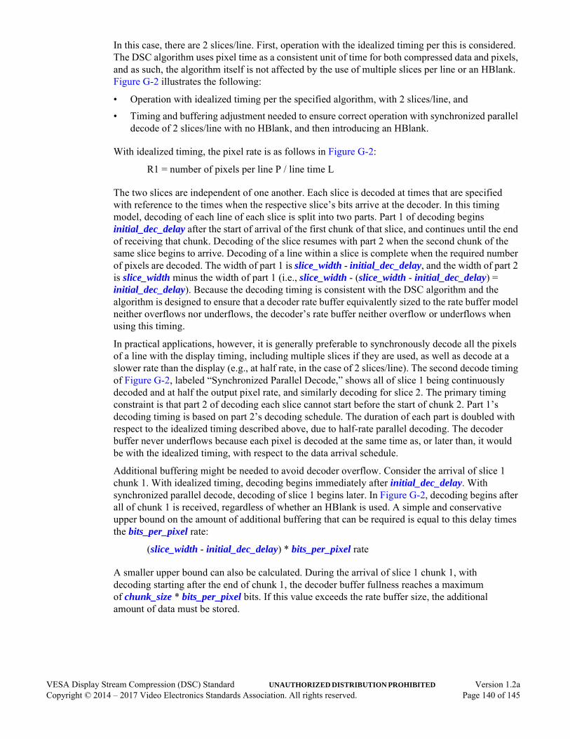
In this case, there are 2 slices/line. First, operation with the idealized timing per this is considered. The DSC algorithm uses pixel time as a consistent unit of time for both compressed data and pixels, and as such, the algorithm itself is not affected by the use of multiple slices per line or an HBlank. Figure G-2 illustrates the following:
• Operation with idealized timing per the specified algorithm, with 2 slices/line, and
• Timing and buffering adjustment needed to ensure correct operation with synchronized parallel decode of 2 slices/line with no HBlank, and then introducing an HBlank.
With idealized timing, the pixel rate is as follows in Figure G-2:
R1 = number of pixels per line P / line time L
The two slices are independent of one another. Each slice is decoded at times that are specified with reference to the times when the respective slice’s bits arrive at the decoder. In this timing model, decoding of each line of each slice is split into two parts. Part 1 of decoding begins initial_dec_delay after the start of arrival of the first chunk of that slice, and continues until the end of receiving that chunk. Decoding of the slice resumes with part 2 when the second chunk of the same slice begins to arrive. Decoding of a line within a slice is complete when the required number of pixels are decoded. The width of part 1 is slice_width - initial_dec_delay, and the width of part 2 is slice_width minus the width of part 1 (i.e., slice_width - (slice_width - initial_dec_delay) = initial_dec_delay). Because the decoding timing is consistent with the DSC algorithm and the algorithm is designed to ensure that a decoder rate buffer equivalently sized to the rate buffer model neither overflows nor underflows, the decoder’s rate buffer neither overflow or underflows when using this timing.
In practical applications, however, it is generally preferable to synchronously decode all the pixels of a line with the display timing, including multiple slices if they are used, as well as decode at a slower rate than the display (e.g., at half rate, in the case of 2 slices/line). The second decode timing of Figure G-2, labeled “Synchronized Parallel Decode,” shows all of slice 1 being continuously decoded and at half the output pixel rate, and similarly decoding for slice 2. The primary timing constraint is that part 2 of decoding each slice cannot start before the start of chunk 2. Part 1’s decoding timing is based on part 2’s decoding schedule. The duration of each part is doubled with respect to the idealized timing described above, due to half-rate parallel decoding. The decoder buffer never underflows because each pixel is decoded at the same time as, or later than, it would be with the idealized timing, with respect to the data arrival schedule.
Additional buffering might be needed to avoid decoder overflow. Consider the arrival of slice 1 chunk 1. With idealized timing, decoding begins immediately after initial_dec_delay. With synchronized parallel decode, decoding of slice 1 begins later. In Figure G-2, decoding begins after all of chunk 1 is received, regardless of whether an HBlank is used. A simple and conservative upper bound on the amount of additional buffering that can be required is equal to this delay times the bits_per_pixel rate:
(slice_width - initial_dec_delay) * bits_per_pixel rate
A smaller upper bound can also be calculated. During the arrival of slice 1 chunk 1, with decoding starting after the end of chunk 1, the decoder buffer fullness reaches a maximum of chunk_size * bits_per_pixel bits. If this value exceeds the rate buffer size, the additional amount of data must be stored.
VESA Display Stream Compression (DSC) Standard UNAUTHORIZED DISTRIBUTION PROHIBITED Version 1.2aCopyright © 2014 – 2017 Video Electronics Standards Association. All rights reserved. Page 140 of 145

With the addition of an HBlank, the timing parameters are modified. Pixel rate R2 > R1; R2 = P / (L - HBlank)us. As above, the earliest time that decoding of slice 1 part 2 can begin is at the start of arrival of slice 1 chunk 2. Slice 1 part 1 is decoded immediately before that. The duration of each part is the same as for synchronized parallel decode with idealized timing, except in this case the rate is R2, so the HBlank times in microseconds are shorter. As with the idealized timing, the decoder buffers never underflow. Also, as with idealized timing, some additional buffering might be required to avoid overflow. The same conservative upper bound as described above applies, and the same approach as described above can be used to determine a smaller upper bound.
VESA Display Stream Compression (DSC) Standard UNAUTHORIZED DISTRIBUTION PROHIBITED Version 1.2aCopyright © 2014 – 2017 Video Electronics Standards Association. All rights reserved. Page 141 of 145

G.2.3 Case – 4 Slices/Line
Figure G-3: 4 Slices/Line
Slic
e 1
part
1
Ide
aliz
ed T
imin
g w
ith
No
HB
lan
k
Tim
ing
wit
h H
Bla
nk
Initi
al d
ecod
e de
lay
@ R
1
Slic
e 2
part
1
Syn
chro
niz
ed P
aral
lel D
eco
de
Slic
e 1
part
1 d
ecod
e
Slic
e de
code
tim
e =
Lus
Slic
e 1
chun
k 1
Slic
e 2
chun
k 1
Slic
e 3
chun
k 1
Slic
e 4
chun
k 1
Slic
e 1
chun
k 2
Slic
e 2
chun
k 2
Slic
e 3
chun
k 2
Slic
e 4
chun
k 2
Slic
e 1
chun
k 3
Slic
e 2
chun
k 3
Slic
e 3
part
1S
lice
4 pa
rt 1
Slic
e 1
part
2S
lice
2 pa
rt 2
Rem
aind
er o
f ini
tial_
dec_
dela
y
Slic
e 2
part
1 d
ecod
e
Slic
e 1
part
1
Initi
al d
ecod
e de
lay
@ R
2S
lice
2pa
rt 1
Syn
chro
niz
ed P
aral
lel D
eco
de
Slic
e 1
part
1 d
ecod
e
Slic
e de
code
tim
e =
(L
- H
Bla
nk)u
s
Slic
e 3
part
1S
lice
4pa
rt 1 Slic
e 1
part
2S
lice
2 pa
rt 2
Rem
aind
er o
f ini
tial_
dec_
dela
y
Slic
e 2
part
1 d
ecod
e
Slic
e 1
chun
k 1
Slic
e 2
chun
k 1
Slic
e 3
chun
k 1
Slic
e 4
chun
k 1
Slic
e 1
chun
k 2
Slic
e 2
chun
k 2
Slic
e 3
chun
k 2
Slic
e 4
chun
k 2
HB
lank
HB
lank
Slic
e 1
chun
k 3
Slic
e 2
chun
k 3
Pix
el r
ate
R1
with
out
HB
lank
= P
pix
els
/ Lu
s lin
e tim
eP
ixel
rat
e R
2 w
ith H
Bla
nk =
P p
ixel
s /
(L -
HB
lank
)us
Del
ay Del
ay
VESA Display Stream Compression (DSC) Standard UNAUTHORIZED DISTRIBUTION PROHIBITED Version 1.2aCopyright © 2014 – 2017 Video Electronics Standards Association. All rights reserved. Page 142 of 145
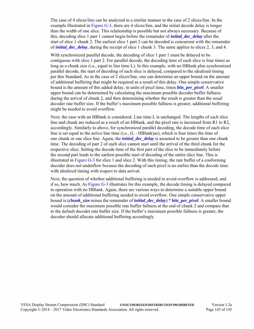
The case of 4 slices/line can be analyzed in a similar manner to the case of 2 slices/line. In the example illustrated in Figure G-3, there are 4 slices/line, and the initial decode delay is longer than the width of one slice. This relationship is possible but not always necessary. Because of this, decoding slice 1 part 1 cannot begin before the remainder of initial_dec_delay after the start of slice 1 chunk 2. The earliest slice 1 part 2 can be decoded is concurrent with the remainder of initial_dec_delay, during the receipt of slice 1 chunk 3. The same applies to slices 2, 3, and 4.
With synchronized parallel decode, the decoding of slice 1 part 1 must be delayed to be contiguous with slice 1 part 2. For parallel decode, the decoding time of each slice is four times as long as a chunk size (i.e., equal to line time L). In this example, with no HBlank plus synchronized parallel decode, the start of decoding of each slice is delayed, compared to the idealized timing per this Standard. As in the case of 2 slices/line, one can determine an upper bound on the amount of additional buffering that might be required as a result of this delay. One simple conservative bound is the amount of this added delay, in units of pixel time, times bits_per_pixel. A smaller upper bound can be determined by calculating the maximum possible decoder buffer fullness during the arrival of chunk 2, and then determining whether the result is greater than the usual decoder rate buffer size. If the buffer’s maximum possible fullness is greater, additional buffering might be needed to avoid overflow.
Next, the case with an HBlank is considered. Line time L is unchanged. The lengths of each slice line and chunk are reduced as a result of an HBlank, and the pixel rate is increased from R1 to R2, accordingly. Similarly to above, for synchronized parallel decoding, the decode time of each slice line is set equal to the active line time (i.e., (L - HBlank)us), which is four times the time of one chunk or one slice line. Again, the initial_dec_delay is assumed to be greater than one chunk time. The decoding of part 2 of each slice cannot start until the arrival of the third chunk for the respective slice. Setting the decode time of the first part of the slice to be immediately before the second part leads to the earliest possible start of decoding of the entire slice line. This is illustrated in Figure G-3 for slice 1 and slice 2. With this timing, the rate buffer of a conforming decoder does not underflow because the decoding of each pixel is no earlier than the decode time with idealized timing with respect to data arrival.
Next, the question of whether additional buffering is needed to avoid overflow is addressed, and if so, how much. As Figure G-3 illustrates for this example, the decode timing is delayed compared to operation with no HBlank. Again, there are various ways to determine a suitable upper bound on the amount of additional buffering needed to avoid overflow. One simple conservative upper bound is (chunk_size minus the remainder of initial_dec_delay) * bits_per_pixel. A smaller bound would consider the maximum possible rate buffer fullness at the end of chunk 2 and compare that to the default decoder rate buffer size. If the buffer’s maximum possible fullness is greater, the decoder should allocate additional buffering accordingly.
VESA Display Stream Compression (DSC) Standard UNAUTHORIZED DISTRIBUTION PROHIBITED Version 1.2aCopyright © 2014 – 2017 Video Electronics Standards Association. All rights reserved. Page 143 of 145
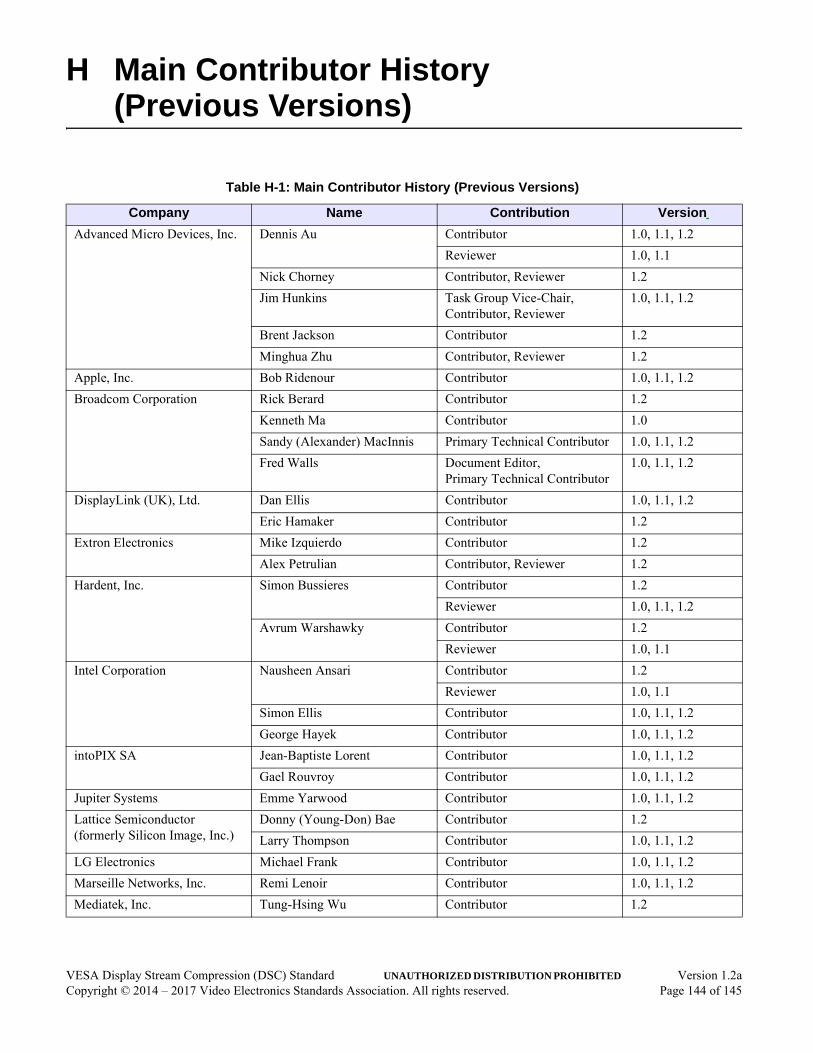
H Main Contributor History (Previous Versions)
Table H-1: Main Contributor History (Previous Versions)
Company Name Contribution Version
Advanced Micro Devices, Inc. Dennis Au Contributor 1.0, 1.1, 1.2
Reviewer 1.0, 1.1
Nick Chorney Contributor, Reviewer 1.2
Jim Hunkins Task Group Vice-Chair, Contributor, Reviewer
1.0, 1.1, 1.2
Brent Jackson Contributor 1.2
Minghua Zhu Contributor, Reviewer 1.2
Apple, Inc. Bob Ridenour Contributor 1.0, 1.1, 1.2
Broadcom Corporation Rick Berard Contributor 1.2
Kenneth Ma Contributor 1.0
Sandy (Alexander) MacInnis Primary Technical Contributor 1.0, 1.1, 1.2
Fred Walls Document Editor, Primary Technical Contributor
1.0, 1.1, 1.2
DisplayLink (UK), Ltd. Dan Ellis Contributor 1.0, 1.1, 1.2
Eric Hamaker Contributor 1.2
Extron Electronics Mike Izquierdo Contributor 1.2
Alex Petrulian Contributor, Reviewer 1.2
Hardent, Inc. Simon Bussieres Contributor 1.2
Reviewer 1.0, 1.1, 1.2
Avrum Warshawky Contributor 1.2
Reviewer 1.0, 1.1
Intel Corporation Nausheen Ansari Contributor 1.2
Reviewer 1.0, 1.1
Simon Ellis Contributor 1.0, 1.1, 1.2
George Hayek Contributor 1.0, 1.1, 1.2
intoPIX SA Jean-Baptiste Lorent Contributor 1.0, 1.1, 1.2
Gael Rouvroy Contributor 1.0, 1.1, 1.2
Jupiter Systems Emme Yarwood Contributor 1.0, 1.1, 1.2
Lattice Semiconductor (formerly Silicon Image, Inc.)
Donny (Young-Don) Bae Contributor 1.2
Larry Thompson Contributor 1.0, 1.1, 1.2
LG Electronics Michael Frank Contributor 1.0, 1.1, 1.2
Marseille Networks, Inc. Remi Lenoir Contributor 1.0, 1.1, 1.2
Mediatek, Inc. Tung-Hsing Wu Contributor 1.2
VESA Display Stream Compression (DSC) Standard UNAUTHORIZED DISTRIBUTION PROHIBITED Version 1.2aCopyright © 2014 – 2017 Video Electronics Standards Association. All rights reserved. Page 144 of 145

MegaChips Technology America(formerly part of STMicroelectronics)
Alan Kobayashi Contributor 1.0, 1.1, 1.2
NVIDIA Corporation David Stears Contributor, Reviewer 1.0, 1.1, 1.2
Parade Technologies, Ltd. Craig Wiley Contributor 1.0, 1.1, 1.2
Qualcomm, Inc. Harris Chan Contributor 1.2
Ramprasad Chandrasekaran Contributor 1.2
James Goel Contributor 1.0, 1.1, 1.2
Reviewer 1.2
Natan Jacobson Contributor 1.0, 1.1, 1.2
Rajan Joshi Contributor 1.0, 1.1, 1.2
Mohsin Riaz Contributor 1.2
Vijayaraghavan Thirumalai Contributor 1.2
Samsung Display Company Greg Cook Contributor 1.2
Dale Stolitzka Task Group Chair, Contributor, Reviewer
1.0, 1.1, 1.2
Samsung Electronics Co., Ltd. Deoksoo Park Reviewer 1.1, 1.2
Taewoo Kim Reviewer 1.1, 1.2
Sharp Laboratories of America Louis Kerofsky Contributor 1.0
Synaptics, Inc. Bruce Chin Contributor, Reviewer 1.0, 1.1, 1.2
Jeff Lukanc Contributor 1.0, 1.1, 1.2
Toshiba America Information Systems, Inc.
Tomoo Yamakage Contributor 1.0, 1.1, 1.2
Table H-1: Main Contributor History (Previous Versions) (Continued)
Company Name Contribution Version
VESA Display Stream Compression (DSC) Standard UNAUTHORIZED DISTRIBUTION PROHIBITED Version 1.2aCopyright © 2014 – 2017 Video Electronics Standards Association. All rights reserved. Page 145 of 145