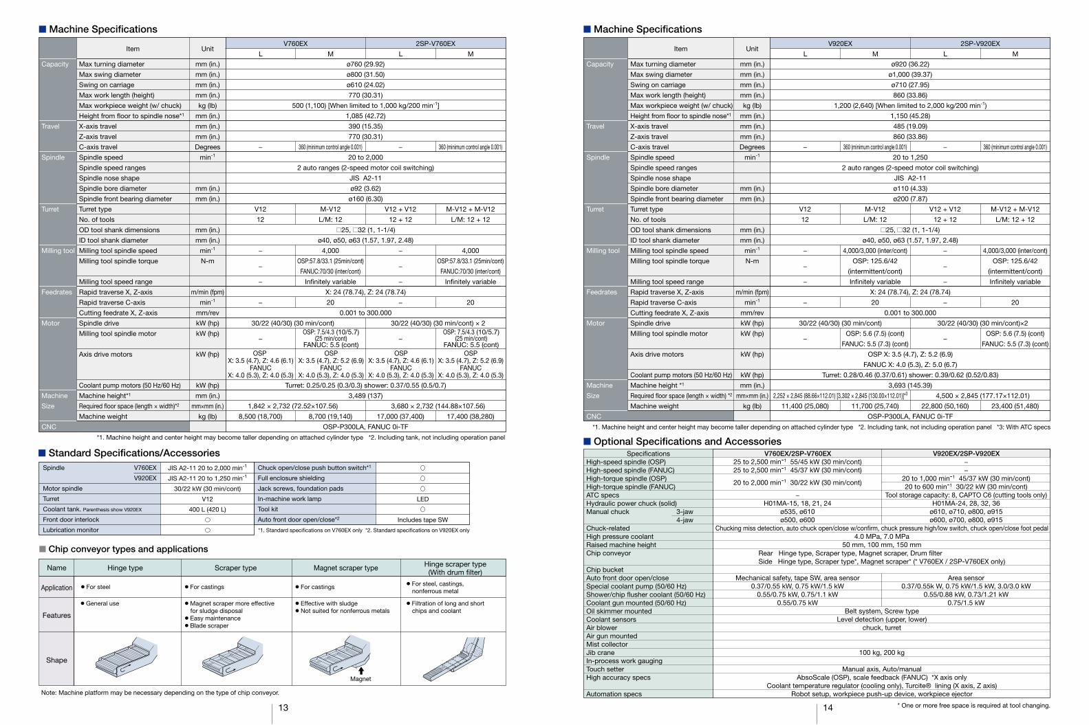
Vertical Turning Lathes
15
Vertical Turning Lathes
Transcript of Vertical Turning Lathes
Vertical Turning Lathes

1 2
Photos shown in this brochureinclude optional equipment.
Minimum installation space,
maximum machining area.
This Okuma vertical lathe provides
the maximum in floor space productivity.
With a smaller footprint, the V920EX has a larger work envelope, higher
performance, and handles more workpiece applications.
The innovative productivity of large-diameter thin and odd-shaped
workpieces makes it ideal for industrial machine parts, as well as large
construction and aircraft components.
Vertical Turning Lathes
Thermo-FriendlyConcept
Collision AvoidanceSystem
MachiningNavi

Valve body
3 4
Stable machining of large workpieces
Outstanding productivity per floor space maximizesthe benefits of high-performance vertical latheapplications for high production efficiency
Machining Area Effectiveness—in a class by itself—
Highly accurate, stable machining and high machining capacity.
The ease of use of a vertical lathe on a base with
Okuma's legendary high-rigidity structure. Greater user-friendliness is
achieved together with a smaller footprint and larger machining area.
Stable machining achieved even with difficult-to-chuck thin, large-diameterworkpieces and unbalanced, odd-shaped components.
Pulley Bearing
Very efficient turn/mill operations
With considerably improved turning and milling capacity, the V760EX and V920EX
deliver powerful cuts for heavy workpiece applications.
Support for machining close accuracieswith decreased operator burden
Okuma’s Thermo-Friendly Concept supports dimensional stability at cycle start/restart points, and improves operator work efficiency by requiring fewer dimensional compensation checks.
Innovative shop floor productivityin many types of production
The 2SP-V760EX and 2SP-V920EX combine left-right symmetric L and R machines operating from a single control. This both shortens lead times and uses factory space effectively.ATC specs are available on the V920EX, preventing interference between the workpiece and adjacent tools and enabling free tool layout.
Easy maintenance with outstanding chip collection
Various improvements were made in chip discharge and inspection locations to reduce operator burden and operation time. This shortens daily maintenance and machining preparation time so that operators can focus on the work.
V920EX

Highly rigid structure with column fixation and saddle movement
5 6
Large machining area can accommodate a wide range of applications Powerful spindle for high-accuracy machining of heavy workpieces.
The features of vertical lathes providefor highly accurate, stable machining
Since the adhesive weight of a workpiece helps clamp it to the chuck’s reference surface.This prevents workpiece warp, and accommodates thin, large-diameter, or heavy workpieces.With fixtures for odd-shaped components, manual part load/unload (without holding the part in place) is also easy.
A flanged headstock minimizes thermal deformation and
vibration in the main spindle, enabling high-accuracy cutting.
Stable machining of large workpieces Powerful, high-accuracy machining
Large machining area achieved with small footprint. Sufficient space (maximum
swing: ø800 mm/V760EX, ø1,000 mm/V920EX) for chucking of odd-shaped
workpieces is also provided, meeting a wide range of customer machining needs.
� Spindle speed: 2,000 min-1
� Max output: 30/22 kW (30 min/cont)� Max torque: 1,257/922 N-m (15 min/cont)
V760EX/2SP-V760EX
� Standard spindle (OSP)� Spindle speed: 1,250 min-1
� Max output: 30/22 kW (30 min/cont)� Max torque: 2,607/1,738 N-m (20 min/cont)
V920EX/2SP-V920EX
� Standard spindle (OSP)
Spindle speed min-1
Sp
ind
le t
orq
ue
Mot
or o
utp
ut
Note: Please refer to pages 17 and 18 for options
Advanced, highly rigid construction enablespowerful and very accurate machining
A rock-solid rectangular column is firmly secured to a rigid base with excellent damping performance. Minimal tool-to-column guideway distance assures the rigidity needed to withstand heavy-duty cutting loads. Moreover, the box ways for the X and Y axes help to achieve heavy-duty cutting of big components at high accuracies.
Photo shows the V920EX
Machining capacity (actual data)
Turning
V760EX
·Heavy-duty cutting:5.0 mm2
� OD turning example (S45C)
Cutting SpeedCutting depth
Feed
150 m/min10 mm0.5 mm/rev
V920EX
Heavy-duty cutting:6.0 mm2
150 m/min10 mm0.6 mm/rev
Z-axis travel
770 mm(V760EX)
860 mm(V920EX)
Swing over saddleø610 mm (V760EX)
ø710 mm (V920EX)
Max turning diameterø760 mm (V760EX)
ø920 mm (V920EX)
90
270
750 min-1
0.5 µmp-p180 0
64
2µm
×5,000
Roundness: 0.5 µm (V760EX actual data)
Cutting conditions
Cutting depth: 0.05 mm
Feed: 0.05 mm/rev
Spindle speed: 750 min-1
Nose R: 0.4 mm
X-axis
Z
10050 500
500
1,000
3,000
5
10
2,000 20
30
4,000 40
93422020 110
kWN-m
1,000
30 kW (30 min)30 kW (20 min)
20 kW (cont)
22 kW (cont)2,607 N-m (20 min)
1,304 N-m (30 min)
1,738 N-m (cont)
956 N-m (cont)
1,250
50 100 1,000
100
500
1,000
2,000
1
5
10
20
30
22820 463
kWN-m
2,000500
1,257 N-m (15 min)
30 kW (30 min)30 kW (15 min)
22 kW (cont)
922 N-m (cont)
618 N-m (30 min)453 N-m (cont)
Spindle speed min-1
Sp
ind
le t
orq
ue
Mot
or o
utp
ut
Z-axis
750 min-1
0.5 µmp-p

7 8
More powerful, can use greater number of tools
Process-intensive machining with powerful milling Easy maintenance with outstanding chip collection
� Spindle speed: 4,000 min-1
� Max output: 7.5/4.3 kW (25 min/cont)� Max torque: 57.8/33.1 N-m (25 min/cont)
V760EX/2SP-V760EX
� Milling tool spindle (OSP)
Smoother daily inspections
The air filter, lubricant tank, hydraulic unit and coolant tank are all located on the back of the machine. This shortens the time needed for daily inspections and improves utilization.
Turning, drilling, end milling all done on a single machine to accommodate a wide range of applications. A much more powerful milling tool spindle than on previous machines enables more powerful cutting and a wider range of process-intensive machining. The turret minimizes interference with neighboring tools so that millling tools can be attached in all 12 locations.
Applications from turning to milling can be done with a single chucking, reducing the work in progress storage space and between process waiting times. Chucking error during workpiece installation can also be eliminated for higher machining accuracies.
� Spindle speed: 4,000 min-1
� Max output: 14/7 kW (5 min/cont)� Max torque: 84/42 N-m (Intermittent/cont)
V920EX/2SP-V920EX
� Milling tool spindle (OSP)
Foolproof chip discharge
Standard chip flushing and a stainless steel chute provide for complete chip discharge to the conveyor (Opt) running directly below the turret. That also cuts down machine operator work-flow interruptions to clean out chips.
Chip discharge system can be adjustedto shop layout requirements
Either side or rear chip conveyors (Opt) can be selected to match chip discharge direction for shop layout.
The operator can easily reach the spindle center 552 mm from the front of the machine. (V760EX)With excellent accessibility the workpiece can be loaded and unloaded smoothly without interference using a crane.
Operator work burden drasticallyreduced with well-designed workflows
V760EX
2SP-V760EX
V920EX Rear chip conveyorsV920EX
Note: Please refer to page18 for options
V760EX
Coolant tank
Air filter
552 mm
100 1,000
10
100
1
10
Spindle speed min-1
4,000
57.8 N-m (25 min)
33.1 N-m (cont)
7.5 kW (25 min)
4.3 kW (cont)
20
40
60
80
5
10
15
1,000 2,000 3,000 4,000
84 N-m (5 min)
42 N-m (cont)
33.4 N-m (5 min)
16.7 N-m (cont)
14 kW (5 min)
7 kW (cont)
Spindle speed min-1
1,24045
Sp
ind
le t
orq
ue
Mot
or o
utp
ut
kWN-m
Sp
ind
le t
orq
ue
Mot
or o
utp
ut
kWN-m
Hydraulic unitLubricanttank
552 mm

9 10
Innovative shop floor productivity in many types ofproduction
High productivity with 2 roles by 1 machine (2SP-V760EX, 2SP-V920EX)
The 2-spindle spec 2SP-V760EX, 2SP-V920EX combines a standard R (right) machine and reverse structure L (left) machine and is operated with a single controller.This gives the maximum productivity with the minimum floor space by shortening lead times and cutting down on intermediate work in progress.The separated right-left structure also enables stable machining that is unaffected by the machining vibration of the other spindle.
� Compact lines that minimize robot travel can be built.
Build automated systems to match your needs
With a design that allows workpiece mounting/dismounting from either the front or side, robots and conveyance equipment can be configured with greater freedom. Flexible, automated systems can be configured in combination with existing equipment.
L (left) machine R (right) machine
Standard maximumtool dimensions
Dedicated station in one location
V920EX ATC Spec Easy to operate ATC by the button next toATC magazine.
Increased tool storage capacity with ATC (*Optional only for V920EX)
Interference between workpiece and adjacent tools that occurs when machining near the center of large-diameter workpieces is prevented with automatic change and storage of tools. This dramatically increases freedom in cutting tool layout. Tool setup also becomes easier. Increased tool storage capacity means that more machining can be done without dividing processes.
� ATC tooling� ATC operation
� Space-saving cells with articulated robots� Connected cells for 1st and 2nd operations can be constructed
in a small space� Side-shutter part load/unload allows uninhibited operator
machine-front access� Operation status can be checked from machine front
� Workpiece push-up device, ejector (Optional)
� Machine supports heavy workpiece load/unload operations.
Greatly reduces operator burden.� Operator simply places workpiece on plate above chuck.� Push-up device automatically raises and lowers workpiece on
chuck, and ejector automatically ejects workpiece from machine.
(V760EX, 2SP-V760EX machines only)ATC magazine (only withuse of turning tool holder)
Tool standards
Max tool length
Max tool weight
C6
12
CAPTO C6
10 kg
450 mm
C8
8
CAPTO C8
15 kg
450
420
(428
)22 (3
0)
5
A
ø100 ø130
50 65
CAPTO C6 CAPTO C8
Figures inparenthesisare for C8.
A
Turret side

11 12
Machining accuracies change significantly due to temperature changes around the machine,heat produced by the machine and heat produced in machining. The Thermo-FriendlyConcept adopts the unique approach of “accepting” these temperature changes to providehighly accurate machining in normal factory environments without special equipment ormeasures to counter temperature changes.
Varying the spindle speed in accordance with the best amplitude and period makes it possible to suppress chatter during turning operations. Tool life can be extended and machining time reduced with use of the optimum cutting conditions, producing significant effects in drilling/boring bar, threading, and grooving applications.
� “ECO Idling Stop” for operation of necessary units only� “ECO Power Monitor” for visual graphic of power� Intermittent/continuous operation of chip conveyor and mist
collector during operation — “ECO Operation” (optional)
Okuma’s Intelligent Technology reducesoperator burden
Manageable Deformation—Accurately Controlled Thermo-Friendly Concept
� TAS-C: Thermo Active Stabilizer—Construction
Thermo Active Stabilizer–Construction (TAS-C) uses information from well-placed sensors and feed shaft information to predict the thermal deformation in machine structure from ambient temperature changes, based on the thermal deformation characteristics of the machine, and finely control the machine.
� Eliminate waste with the Thermo-Friendly Concept
Okuma's Thermo-Friendly Concept maintains dimensional stability not only when temperature changes, but also during machine start-up and machining restart. Warming-up time is reduced since thermal deformation is stabilized, decreasing the time and effort needed for dimensional compensation during restarts.
Cutting condition search
Machining Navi L-g (Optional)
Machining Navi OFF
Machining Navi ON
All energy-saving technologies that can be used by a machine are available
Machining dimensional change over time: Less than: ø8 µmActual results with turning on a V760EX (ambient temperature: 8°C change)
Smooth, comfortable operation with the feeling of using a smart phone
Improved rendering performance and use of a multi-touch panel achieve intuitive graphical operation. Moving, enlarging, reducing, and rotating 3D models, as well as list views of tool data, programs, and other information can be accomplished through smooth, speedy operations with the same feel as using a smart phone. The screen display layout on the operation screen can also be changed to suit operator preferences and customized for the novice and/or veteran machinists.
“Just what we wanted.”— Refreshed OSP suite apps
This became possible through the addition of Okuma's machining expertise based on requests we heard from real, machine-shop customers. The brainpower packed into the CNC, built by machine tool manufacturer, will “empower shop floor” management.
Smoothoperations even
with wet orwork-gloved
hands
The specified spindle output (red line: short time rating, green line: continuous rating) and the spindle output in current cutting (blue circle) are simultaneously displayed on the screen, for real-time view of power reserve during cutting. This allows speeding up cutting by increasing the spindle speed or feed rate while monitoring the graph to ensure that the blue circle does not cross the lines.
Spindle Output MonitorIncreased productivity through visualization of motor power reserve
Scheduled Program EditorEasy programing without keying in code
E-mail NotificationMonitoring operating status even when away from the machine
With revamped operation and responsiveness—ease of use for machine shops first!
Smart factories implement advanced digitization and networking (IoT) in manufacturing to achieve enhanced productivity and added value. The OSP has evolved tremendously as a CNC suited to advanced intelligent technology. Okuma’s new control uses the latest CPUs for a tremendous boost in operability, rendering performance, and processing speed. The OSP suite also features a full range of useful apps that could only come from a machine-tool manufacturer, making smart manufacturing a reality.
The Next-Generation Intelligent CNC
� Cycle time: 60 secX-axis stroke 60 mm4 reciprocating movements/cycle
� Cutting conditions Spindle speed : 1,600 min-1
Cutting depth : 0.05 mm Feed : 0.05 mm/rev� Workpiece material : BSB� Coolant on
Note: The “actual data” referred to above for this brochurerepresent examples, and may not be obtained due todifferences in specifications, tooling, cutting, andother conditions.
OD dimensional change Ambient temperature change
0
20
15
10
-5
-10
-15
-20 20
25
30
4 8 12
Elapsed time (Hr)
16 20 24
OD
dim
ensi
onal
cha
nge
(øµm
)
8°C change
ø8 µm
Room temp
EnlargeRotate
5
0
1413
*1. Machine height and center height may become taller depending on attached cylinder type *2. Including tank, not including operation panel
*1. Machine height and center height may become taller depending on attached cylinder type *2. Including tank, not including operation panel *3: With ATC specs
� Standard Specifications/Accessories
� Machine Specifications
� Chip conveyor types and applications
Note: Machine platform may be necessary depending on the type of chip conveyor.
� Machine Specifications
� Optional Specifications and Accessories
* One or more free space is required at tool changing.
Capacity
Travel
Spindle
Turret
Milling tool
Feedrates
Motor
Machine
Size
CNC
Item Unit
mm (in.)
mm (in.)
mm (in.)
mm (in.)
kg (lb)
mm (in.)
mm (in.)
mm (in.)
Degrees
min-1
mm (in.)
mm (in.)
mm (in.)
mm (in.)
min-1
N-m
m/min (fpm)
min-1
mm/rev
kW (hp)
kW (hp)
kW (hp)
kW (hp)
mm (in.)
mm×mm (in.)
kg (lb)
V760EX
ML L M
2SP-V760EX
−
V12
12
−
−
−
−
−
8,500 (18,700)
360 (minimum control angle 0.001)
M-V12
L/M: 12
4,000
OSP:57.8/33.1 (25min/cont)
FANUC:70/30 (inter/cont)
Infinitely variable
20
8,700 (19,140)
−
V12 + V12
12 + 12
−
−
−
−
−
17,000 (37,400)
360 (minimum control angle 0.001)
M-V12 + M-V12
L/M: 12 + 12
4,000
OSP:57.8/33.1 (25min/cont)
FANUC:70/30 (inter/cont)
Infinitely variable
20
17,400 (38,280)
ø760 (29.92)
ø800 (31.50)
ø610 (24.02)
770 (30.31)
500 (1,100) [When limited to 1,000 kg/200 min-1]
1,085 (42.72)
390 (15.35)
770 (30.31)
20 to 2,000
2 auto ranges (2-speed motor coil switching)
JIS A2-11
ø92 (3.62)
ø160 (6.30)
25, 32 (1, 1-1/4)
ø40, ø50, ø63 (1.57, 1.97, 2.48)
X: 24 (78.74), Z: 24 (78.74)
0.001 to 300.000
Turret: 0.25/0.25 (0.3/0.3) shower: 0.37/0.55 (0.5/0.7)
3,489 (137)
OSP-P300LA, FANUC 0i-TF
Max turning diameter
Max swing diameter
Swing on carriage
Max work length (height)
Max workpiece weight (w/ chuck)
Height from floor to spindle nose*1
X-axis travel
Z-axis travel
C-axis travel
Spindle speed
Spindle speed ranges
Spindle nose shape
Spindle bore diameter
Spindle front bearing diameter
Turret type
No. of tools
OD tool shank dimensions
ID tool shank diameter
Milling tool spindle speed
Milling tool spindle torque
Milling tool speed range
Rapid traverse X, Z-axis
Rapid traverse C-axis
Cutting feedrate X, Z-axis
Spindle drive
Milling tool spindle motor
Axis drive motors
Coolant pump motors (50 Hz/60 Hz)
Machine height*1
Required floor space (length × width)*2
Machine weight
30/22 (40/30) (30 min/cont)
1,842 × 2,732 (72.52×107.56)
30/22 (40/30) (30 min/cont) × 2
3,680 × 2,732 (144.88×107.56)
Spindle
Motor spindle
Turret
Coolant tank. Parenthesis show V920EX
Front door interlock
Lubrication monitor
V760EX
V920EX
JIS A2-11 20 to 2,000 min-1
JIS A2-11 20 to 1,250 min-1
30/22 kW (30 min/cont)
V12
400 L (420 L)
Chuck open/close push button switch*1
Full enclosure shielding
Jack screws, foundation pads
In-machine work lamp
Tool kit
Auto front door open/close*2
*1. Standard specifications on V760EX only *2. Standard specifications on V920EX only
LED
Includes tape SW
Name
Application
Features
Shape
Hinge type Scraper type Magnet scraper type
� For steel � For castings � For castings
� Magnet scraper more effective for sludge disposal
� Easy maintenance� Blade scraper
� General use � Effective with sludge� Not suited for nonferrous metals
Hinge scraper type(With drum filter)
� For steel, castings, nonferrous metal
� Filtration of long and short chips and coolant
Magnet
Capacity
Travel
Spindle
Turret
Milling tool
Feedrates
Motor
Machine
Size
CNC
Item Unit
mm (in.)
mm (in.)
mm (in.)
mm (in.)
kg (lb)
mm (in.)
mm (in.)
mm (in.)
Degrees
min-1
mm (in.)
mm (in.)
mm (in.)
mm (in.)
min-1
N-m
m/min (fpm)
min-1
mm/rev
kW (hp)
kW (hp)
kW (hp)
kW (hp)
mm (in.)
mm×mm (in.)
kg (lb)
Max turning diameter
Max swing diameter
Swing on carriage
Max work length (height)
Max workpiece weight (w/ chuck)
Height from floor to spindle nose*1
X-axis travel
Z-axis travel
C-axis travel
Spindle speed
Spindle speed ranges
Spindle nose shape
Spindle bore diameter
Spindle front bearing diameter
Turret type
No. of tools
OD tool shank dimensions
ID tool shank diameter
Milling tool spindle speed
Milling tool spindle torque
Milling tool speed range
Rapid traverse X, Z-axis
Rapid traverse C-axis
Cutting feedrate X, Z-axis
Spindle drive
Milling tool spindle motor
Axis drive motors
Coolant pump motors (50 Hz/60 Hz)
Machine height *1
Required floor space (length × width) *2
Machine weight
V920EX
ML L M
2SP-V920EX
−
V12
12
−
−
−
−
−
11,400 (25,080)
360 (minimum control angle 0.001)
M-V12
L/M: 12
4,000/3,000 (inter/cont)
OSP: 125.6/42
(intermittent/cont)
Infinitely variable
20
OSP: 5.6 (7.5) (cont)
FANUC: 5.5 (7.3) (cont)
11,700 (25,740)
−
V12 + V12
12 + 12
−
−
−
−
−
22,800 (50,160)
360 (minimum control angle 0.001)
M-V12 + M-V12
L/M: 12 + 12
4,000/3,000 (inter/cont)
OSP: 125.6/42
(intermittent/cont)
Infinitely variable
20
OSP: 5.6 (7.5) (cont)
FANUC: 5.5 (7.3) (cont)
23,400 (51,480)
ø920 (36.22)
ø1,000 (39.37)
ø710 (27.95)
860 (33.86)
1,200 (2,640) [When limited to 2,000 kg/200 min-1)
1,150 (45.28)
485 (19.09)
860 (33.86)
20 to 1,250
2 auto ranges (2-speed motor coil switching)
JIS A2-11
ø110 (4.33)
ø200 (7.87)
25, 32 (1, 1-1/4)
ø40, ø50, ø63 (1.57, 1.97, 2.48)
X: 24 (78.74), Z: 24 (78.74)
0.001 to 300.000
OSP X: 3.5 (4.7), Z: 5.2 (6.9)
FANUC X: 4.0 (5.3), Z: 5.0 (6.7)
Turret: 0.28/0.46 (0.37/0.61) shower: 0.39/0.62 (0.52/0.83)
3,693 (145.39)
OSP-P300LA, FANUC 0i-TF
SpecificationsHigh-speed spindle (OSP)High-speed spindle (FANUC)High-torque spindle (OSP)High-torque spindle (FANUC)ATC specsHydraulic power chuck (solid)Manual chuck 3-jaw 4-jawChuck-relatedHigh pressure coolantRaised machine heightChip conveyor
Chip bucketAuto front door open/closeSpecial coolant pump (50/60 Hz)Shower/chip flusher coolant (50/60 Hz)Coolant gun mounted (50/60 Hz)Oil skimmer mountedCoolant sensorsAir blowerAir gun mountedMist collectorJib craneIn-process work gaugingTouch setterHigh accuracy specs
Automation specs
25 to 2,500 min-1 55/45 kW (30 min/cont)25 to 2,500 min-1 45/37 kW (30 min/cont)
20 to 2,000 min-1 30/22 kW (30 min/cont) −
H01MA-15, 18, 21, 24ø535, ø610ø500, ø600
Mechanical safety, tape SW, area sensor0.37/0.55 kW, 0.75 kW/1.5 kW
0.55/0.75 kW, 0.75/1.1 kW0.55/0.75 kW
Chucking miss detection, auto chuck open/close w/confirm, chuck pressure high/low switch, chuck open/close foot pedal4.0 MPa, 7.0 MPa
50 mm, 100 mm, 150 mm
Belt system, Screw typeLevel detection (upper, lower)
chuck, turret
100 kg, 200 kg
Manual axis, Auto/manualAbsoScale (OSP), scale feedback (FANUC) *X axis only
Coolant temperature regulator (cooling only), Turcite® lining (X axis, Z axis)Robot setup, workpiece push-up device, workpiece ejector
V760EX/2SP-V760EX−−
20 to 1,000 min-1 45/37 kW (30 min/cont)20 to 600 min-1 30/22 kW (30 min/cont)
Tool storage capacity: 8, CAPTO C6 (cutting tools only)H01MA-24, 28, 32, 36
ø610, ø710, ø800, ø915ø600, ø700, ø800, ø915
Area sensor0.37/0.55k W, 0.75 kW/1.5 kW, 3.0/3.0 kW
0.55/0.88 kW, 0.73/1.21 kW0.75/1.5 kW
V920EX/2SP-V920EX
30/22 (40/30) (30 min/cont)
2,252 × 2,845 (88.66×112.01) [3,302 × 2,845 (130.00×112.01)]*3
30/22 (40/30) (30 min/cont)×2
4,500 × 2,845 (177.17×112.01)
Rear Hinge type, Scraper type, Magnet scraper, Drum filterSide Hinge type, Scraper type*, Magnet scraper* (* V760EX / 2SP-V760EX only)
OSP: 7.5/4.3 (10/5.7)(25 min/cont)
FANUC: 5.5 (cont)
OSP: 7.5/4.3 (10/5.7)(25 min/cont)
FANUC: 5.5 (cont)OSP
X: 3.5 (4.7), Z: 4.6 (6.1)FANUC
X: 4.0 (5.3), Z: 4.0 (5.3)
OSPX: 3.5 (4.7), Z: 5.2 (6.9)
FANUCX: 4.0 (5.3), Z: 4.0 (5.3)
OSPX: 3.5 (4.7), Z: 4.6 (6.1)
FANUCX: 4.0 (5.3), Z: 4.0 (5.3)
OSPX: 3.5 (4.7), Z: 5.2 (6.9)
FANUCX: 4.0 (5.3), Z: 4.0 (5.3)

15 16
*1. NML: Normal, 3D: Real 3D simulation, OT-IGF: One-Touch IGF, OTM: One-Touch ME: Economy, D: Deluxe
*2. Real 3-D Simulation included*3. Engineering discussions required.Note: � Triangle items for M function (milling tool) machines only.
� Standard Specifications
FANUC 0i-TF
� Optional Specifications
� Standard Specifications
� Optional Specifications
The Next-Generation Intelligent CNC
Basic Specs
Operations
Communications/Networks
High speed/accuracy
Energy-saving function
Control
Position feedback
Min / Max inputs
Feed
Spindle control
Tool compensation
Display
Self-diagnostics
Program capacity
suite apps
suite operation
Easy Operation
Programing
Machineoperations
MacMan
Thermo Active Stabilizer–Construction (TAS-C)
High speed/accuracy
ECO suite
�
�
�
�
�
�
�
�
�
�
�
�
�
�
�
�
�
�
�
�
�
�
�
�
�
�
�
�
�
�
�
�
�
�
�
�
�
�
�
�
�
�
�
�
�
�
�
�
�
�
�
�
�
�
�
�
�
�
�
�
�
�
�
�
Optional Specifications
New Operations
Advanced One-Touch IGF-L *2
Advanced One-Touch IGF-L Multitasking *2
Programming
Circular threading
Program notes
User task 2 I/O variables, 8 each
Work coor- 10 sets
dinate 50 sets
systemselect 100 sets
Tool compen- Tool compensation 64 sets
sation Tool compensation 96 sets
(Std: 32 sets) Tool compensation 200 sets
Tool compensation 999 sets
Common variables 1,000 sets (Std: 200 sets)
Thread matching (spindle orientation required)
Threading slide hold (G34, G35)
Variable spindle speed threading (VSST)
Inverse time feed
Milling machines Coordinate convert
pecs Profile generate
Monitoring
Real 3-D simulation
Cycle time over check
Load monitor (spindle, feed axis)
Load monitor no-load detection (load monitor ordered)
Tool life management
Tool life warning
Operation end buzzer
Chucking miss detection
Work counters Count only
Cycle stop
Start disabled
Hour meters Power ON
Spindle rotation
NC operating
NC operation monitor (counter, totaling)
NC work counter (stops at full count with alarm)
Status indicator (triple lamp) Type C [Type A, Type B]
Measuring
In-process work gauging
Z-axis automatic zero offset by touch sensor
C-axis automatic zero offset by touch sensor
Gauge data output File output
Post-process Set levels (5-level, 7-level)
work gauging BCD
interface RS-232-C (dedicated channel)
Touch setter [M, A]
Turning: X, Z simultaneous 2-axis. Multitasking: X, Z, C simultaneous 3-axis
OSP full range absolute position feedback (zero point return not required)
8-digit decimal, ±99999.999 to 0.001 mm (±3937.0078 to 0.0001 in.), 0.001°, Decimal:1 µm, 10 µm, 1 mm (0.0001,1 in.) (1°, 0.01°, 0.001°)
Override: 0 to 200%
Direct spindle speed commands (S4) override 50 to 200%, Constant cutting speed, optimum turning speed designate
Tool selection: 32 sets, tool offset: 32 sets
15-inch color display operational panel, multi-touch panel operations
Automatic diagnostics and display of program, operation, machine, and NC system problems
Program storage: 2 GB, operation buffer: 2 MB
Applications to graphically visualize and digitize information needed on the shop floor
Highly reliable touch panel suited to shop floors. One-touch access to suite apps.
“Single-mode operation” to complete a series of operations. Advanced operation panel/graphics facilitate smooth machine control
Program management, edit, multitasking, scheduled programs, fixed cycles, special fixed cycles, tool nose R compensation, fixed drilling
cycles, arithmetic functions, logic statements, trig functions, variables, branch statements, auto programming (LAP4), programming help
MDI, manual (rapid traverse, manual cutting feed, pulse handle), load meter, operations help, alarm help, sequence, return,
manual interrupt & auto return, threading slide hold, data I/O, spindle orientation (electric)
Machining Management: machining results, machine utilization, fault data compile & report, external output
USB ports, Ethernet
Compensates for thermal deformation error in the machine structure due to ambient temperature changes
Hi-G control, Ethernet
ECO Idling Stop, ECO Power Monitor
E D E D E D
NML 3D OT-IGF
E D
OTM
Included in machine specs
Included in machine specs
Included in machine specs
External Input/Output and Communication Functions
RS-232-C connector
DNC link DNC-T3
DNC-C/Ethernet
DNC-DT
USB (additional) 2 additional ports possible
Automation/Untended Operation
Auto power shutoff MO2, alarm
Warmup function (by calendar timer)
Tool retract cycle
External A (pushbutton) 8 types
program B (rotary switch) 8 types
selections C1 (digital switch) BCD, 2-digit
C2 (external input) BCD, 4-digit
Third party Type B (machine)
robotand loader Type C (robot and loader)
interface *3 Type D
Type E
Cycle time Operation time reduction
reduction *3
High-Speed/High-Accuracy Functions
Pitch error compensation
AbsoScale detection *3
Hi-Cut Pro
ECO suite (energy saving function)
ECO Operation
Other Functions
Collision Avoidance System (CAS)
One-Touch Spreadsheet
Machining Navi L-g
Harmonic spindle speed control (HSSC)
Spindle dead-slow cutting
Spindle speed setting
Manual cutting feed
Spindle power peak cutting
Short circuit breaker
External M signals [2 sets, 4 sets, 8 sets]
Edit interlock
OSP-VPS (virus protection system)
Illumination in control panel
Air conditioning in control panel
AC 100V 1A plug
Optional Specifications
�
�
�
�
�
�
�
�
�
�
�
�
�
�
�
�
�
�
�
�
�
�
E D E D E D
NML 3D OT-IGF
E D
OTM
No. of controlled
axes
Interpolation
system
Command system
Minimum input
increment
Min command value
Operating panel
Monitoring
Machine operations
2 simultaneous axes with X and Z axes,
3 simultaneous axes with multitasking on X, Z, and
C axes.
Positioning, straight line, taper, arc, threading, taper
Fine coordinate interpolation, Cylindrical interpolation
(M spec only)
Parallel absolute incremental command
Both X, Z axes 0.001 mm
±99999.999 mm, decimal point input
10.4 in color LCD
Display language: English / Japanese
Operating time, no. of parts display
Electronic buzzer
Graphic display
Tool life management (FANUC software)
Constant peripheral speed control
Spindle orientation (1 point, M19)
Continuous threading
Program input
Compensation
Program memory capacity 512KB
No. registered programs: 400
Chamfering/corner radius
Complex shape fixed cycle ( + )
Extension program editing
USB memory input/output (program input/output only)
Custom macro
Custom macros, additional common variables(total is 500)
Programmable data input
High-speed skip
Program protection key switch
Background editing
Fixed drilling cycle (M spec)
Inch/metric conversion
Thermal deformation compensation
Nose-radius comp
tool dimensions/wear compensation
Tool compensations (64/system)
AI contouring control
Monitor
Machine operations
Program input
Automation
Other
3-step
Okuma software Spare tool jump
Spindle + feed axes
4-point (M19, 119, 129, 139)
Digital switch with 2-digit indicator
G54 to G59
2 pts, 4 pts, 8 pts
LED
Temperature regulator (cooler only), dehumidifier
In operation panel, control panel
Tool counter
Work counter
Multi-counter
Hour meters
Status indicator
Tool life management
Abnormal load detection
Oriented spindle stop
Auto power shut-off
Circuit breaker
External program selection
System selection Tool compensation
Program restart
Spare M codes
Memory type pitch error compensation
Robot interface
RS-232-C input/output connector
Illumination in control panel
Air conditioning within control panel
AC 100V 1A plug

17 18
� Speed 2,000 min-1
� Max output 30/22 kW (30 min/cont)
� Max torque 1,290/946 N-m (30 min/cont)
� Spindle output/torque diagram (Optional)
� Speed 2,500 min-1
� Max output 55/45 kW (30 min/cont)
� Max torque 834/682 N-m (30 min/cont)
High-speed spindle (OSP)
� Speed 600 min-1
� Max output 30/22 kW (30 min/cont)
� Max torque 5,264/3,246 N-m (30 min/cont)
High-torque spindle (FANUC)
� Speed 1,250 min-1
� Max output 30/22 kW (30 min/cont)
� Max torque 2,608/1,608 N-m (30 min/cont)
� Speed 1,000 min-1
� Max output 45/37 kW (30 min/cont)
� Max torque 5,319/4,373 N-m (30 min/cont)
High-torque spindle (OSP)
Standard spindle (FANUC)
High-speed spindle (FANUC)
� Speed 2,000 min-1
� Max output 30/22 kW (30 min/cont)
� Max torque 2,910/2,140 N-m (30 min/cont)
High-torque spindle (FANUC)High-torque spindle (OSP)� Speed 2,000 min-1
� Max output 30/22 kW (30 min/cont)
� Max torque 2,840/2,082 N-m (30 min/cont)
V760EX/2SP-V760EX
Standard spindle (FANUC)
V920EX/2SP-V920EX
� Milling tool spindle output/torque diagram (FANUC)
V760EX/2SP-V760EX V920EX/2SP-V920EX
� Speed 4,000 min-1
� Max output 5.5 kW (cont)
� Max torque 70/30 N-m (Intermittent/cont)
� Speed 4,000 min-1
� Max output 5.5 kW (cont)
� Max torque 115/40 N-m (Intermittent/cont)
100 1,000
100
1,000
3,000
1
10
30
63025 1,960
2,500
834 N-m (30 min)
55 kW (30 min)
682 N-m (cont)
45 kW (cont)
100 1,000
100
1,000
3,000
1
10
30
83325 2,220
2,500
516 N-m (30 min)
45 kW (30 min)
37 kW (cont)
100 1,000
100
1,000
3,000
1
10
30
22220 579
Sp
ind
le t
orq
ue
Mot
or o
utp
ut
2,000
1,158463
1,544
30 kW (30 min)
22 kW (cont)
100 1,000
100
1,000
3,000
1
10
30
47220 101 205 232
2,000
30 kW (30 min)
1,026
2,840 N-m (30 min)
1,396 N-m (30 min)
2,082 N-m (cont)
1,235 N-m (30 min)1,024 N-m (cont)
905 N-m (cont)607 N-m (30 min)
445 N-m (cont)
22 kW (cont)
20 20546226
256
472
100 1,000
100
1,000
3,000
1
10
30
2,000
30 kW (30 min)2,910 N-m (30 min)
1,400 N-m (30 min)
2,140 N-m (cont)
1,024 N-m (cont) 22 kW (cont)
1,270 N-m (30 min)930 N-m (cont)
607 N-m (30 min)445 N-m (cont)
100 1,000
100
1,000
3,000
1
10
30
20
2,000
110
371
275
1,250
824
206
30 kW (30 min)
18.5 kW (cont)
22 kW (cont)
100 1,000
1,000
5,000
10
50
20420 38 81
45 kW (30 min)
539
5,319 N-m (30 min)
2,811 N-m (30 min)2,311 N-m (cont)
2,108 N-m (30 min)1,734 N-m (cont)
153
4,373 N-m (cont)3,989 N-m (30 min)
3,280 N-m (cont)
37 kW (cont)
108
100 600200
500
200
1,000
3,000
5,000
5
10
30
5,264 N-m (30 min)
2,808 N-m (30 min)
3,246 N-m (cont)
2,059 N-m (cont)
30 kW (30 min)
22 kW (cont)
18.5 kW (cont)
590 1,572684
513 1,1791,026
1,000
80
60
40
20
10
5
15
3,000 4,0002,000
70 N-m(intermittent/cont) 14.7 kW
(intermittent working range)
30 N-m (cont)5.5 kW (cont)
17.5 N-m (cont)
1,000
80
60
40
20
100
120
10
5
20
25
30
15
3,000 4,0002,000
115 N-m (intermittent working range)
60.1 N-m(intermittent working range)
25.2 kW(intermittent working range)
40 N-m(cont)
5.5 kW (cont)
18 N-m (cont)
1,290 N-m (30 min)946 N-m (cont)
618 N-m (30 min)453 N-m (cont)
1025420 136 408
423 N-m (cont)
� Speed 2,500 min-1
� Max output 45/37 kW (30 min/cont)
� Max torque 516/423 N-m (30 min/cont)
3000 min-1 and higheris an intermittentworking range.
3000 min-1 and higher is anintermittent working range.
kWN-m
2,608 N-m (30 min)
1,608 N-m (cont)
1,391 N-m (30 min)1,020 N-m (cont)
Spindle speed min-1
Sp
ind
le t
orq
ue
Mot
or o
utp
ut
kWN-m
Spindle speed min-1
Sp
ind
le t
orq
ue
Mot
or o
utp
ut
kWN-m
Spindle speed min-1
Sp
ind
le t
orq
ue
Mot
or o
utp
ut
kWN-m
Spindle speed min-1
Sp
ind
le t
orq
ue
Mot
or o
utp
ut
kWN-m
Spindle speed min-1
Sp
ind
le t
orq
ue
Mot
or o
utp
ut
kWN-m
Spindle speed min-1
Sp
ind
le t
orq
ue
Mot
or o
utp
ut
kWN-m
Spindle speed min-1
Sp
ind
le t
orq
ue
Mot
or o
utp
ut
kWN-m
Spindle speed min-1
Sp
ind
le t
orq
ue
Mot
or o
utp
ut
kWN-m
Spindle speed min-1
Sp
ind
le t
orq
ue
Mot
or o
utp
ut
kWN-m
Spindle speed min-1

� Tooling kitV760EX/2SP-V760EX
19 20
� Tooling SystemV760EX/2SP-V760EX
� Tooling SystemV920EX/2SP-V920EX Unit: mmUnit: mm
OD- 25
OD- 25
OD- 25
ID-H40
BS 12-H40
BS 16-H40
BS 20-H40
BS 25-H40
DS MT No.1-H40
DS MT No.2-H40
DS MT No.3-H40
DS MT No.4-H40
Turningturret
6
3
2
6
2
2
2
2
1
1
1
1
Boring barø40, ø50, ø63
V12 turret(ø500 across flats)
Boring bar sleeveø12-H40ø16-H40ø20-H40ø25-H40ø32-H40ø32-H50ø40-H50
ID tool25, 32
Max turning diaø760
Max turning diaø650
* Turret compatible with 2SP-V60/V60R.There is compatibility with the 2SP-V60/V60Rand holders.
* Oil hole drills and boring bars require IDoil-hole toolholder bases (Opt).
V12 turret
M-V12 turret
Boring bar sleeveø12-H40ø16-H40ø20-H40ø25-H40ø32-H40ø32-H50ø40-H50
Max turning diaø760
Max turning diaø650
Axial mill unit Radial mill unit
V12 turret(ø500 across flats)
OD- 25
OD- 25
OD- 25
ID-H40
BS 12-H40
BS 16-H40
BS 20-H40
BS 25-H40
DS MT No.1-H40
DS MT No.2-H40
DS MT No.3-H40
DS MT No.4-H40
Turningturret
6
3
2
6
2
2
2
2
1
1
1
1
V12 turret
M-V12 turret
* Turret compatible with 2SP-V80/V80R. There is compatibility with the 2SP-V80/V80R and holders.(2SP-V80/80R and holder not compatible prior to minor change in 2007.)
* Oil hole drills and boring bars require ID oil-hole toolholder bases (Opt).
Unit: mmUnit: mm
Boring barø40, ø50, ø63
V12 turret(ø600 across flats)
ID tool25, 32
Max turning diaø920
Max turning diaø840
Boring bar sleeveBS 12-H40BS 16-H40BS 20-H40BS 25-H40BS 32-H40BS 32-H50BS 40-H50
ATC holder
(CAPTO C8)
ATC holder
(CAPTO C6)
Boring bar sleeveø12-H40ø16-H40ø20-H40ø25-H40ø32-H40ø32-H50ø40-H50
Max turning diaø920
Max turning diaø840
M-V12 turret(ø600 across flats)
ATC holder
(CAPTO C8)
ATC holder
(CAPTO C6)
Axial mill unitRadial mill unit
Drill sleeveDS MT NO.1-H40DS MT NO.2-H40DS MT NO.3-H40DS MT NO.4-H40
ID-H40ID-H50ID-H63
OD- 25OD- 32
OD- 25OD- 32
OD- 25OD- 32
Drill sleeveMT NO.1-H40MT NO.2-H40MT NO.3-H40MT NO.4-H40
OD- 25OD- 32
OD- 25OD- 32
OD- 25OD- 32
ID-H40ID-H50ID-H63
Drill sleeveDS MT NO.1-H40DS MT NO.2-H40DS MT NO.3-H40DS MT NO.4-H40
ID-H40ID-H50ID-H63
Drill sleeveMT NO.1-H40MT NO.2-H40MT NO.3-H40MT NO.4-H40
ID-H40ID-H50ID-H63
� Tooling kitV920EX/2SP-V920EX
�Boring barø40, ø50, ø63
�ID tool25, 32
�Collet(Alps tool AR40)
[ø4 to 26 (ø1 mm pitch)]
�Commercially available items
�Boring barø40, ø50, ø63
�ID tool25, 32
�Commerciallyavailable items
�Colletø8, 10, 12, 14, 16, 18, 2022, 24, 25, 26, 28, 30, 32
ID turning OD turning
ID turning OD turning
Mill/drill tooling
ID turning OD turning
ID turning OD turning
Mill/drill tooling
[ ]
OD- 25OD- 32
OD- 25OD- 32
OD- 25OD- 32
OD- 25OD- 32
OD- 25OD- 32
OD- 25OD- 32

21 22
� Working RangesV760EX/2SP-V760EX V920EX/2SP-V920EXUnit: mm Unit: mm
� V12 turret � V12 turret
� M-V12 turret � M-V12 turret
<OD toolholder> <ID toolholder>
ID toolholder ID-H40 ID-H50 ID-H63
OD toolholder OD- 25 ( ): OD- 32
*The V12 turret and V12 multitasking turret have different shapes.
<Axial mill toolholder> <Radial mill toolholder>
<OD toolholder> <ID toolholder>
ID-H40ID-H50ID-H63
OD toolholder OD- 32 ( ): OD- 25
<Axial mill toolholder> <Radial mill toolholder>
90
460
390 travel
55 (65)
35 (45)
7 (8
)
52 (5
3)
335 (325) 125 (135)
125
990
770
trav
el16
8 (1
67)
H01MA15
125
max 35
125
990
770
trav
el
150
220
150
460
390 travel
50
340
H01MA15
120
H01MA15
45°
57
390 travel1
391 69
460
275
70
55
770
trav
el
119
125
990
250119
H01MA15
45°
57
390 travel
10
380 80
460
168
5277
0 tr
avel
119
125
990
120
250119
435
55550
X-axis travel 485 120
H01MA-24
Z-a
xis
trav
el 8
6020
0
4013
5
175
100
125
1,06
0
555
X-axis travel 485
H01MA-24
460 95
45 (35) 50 (60)
25
60 (5
2)14
0 (1
48)
8(7)
Z-a
xis
trav
el 8
60
125
1,06
0
4013
5
175
100
X-axis travel 485
27.7
98
Z-a
xis
trav
el 8
6025
4
1,06
0
555
181.5
28
H01MA-24
4013
5
175
100
4971
54
(7)
(70)
(ø32
)
ø433
9.7
Z-a
xis
trav
el 8
6011
6.5
137.
5
1,06
012
5
H01MA-24
4013
5
100
(ø32)
X-axis travel 485
70.3
80
30055510
4954
83.5133 ø433
70.3
300
(7)
175
71
*For both multitasking turret and ATC specs.
max 35
max
200
125

23 24
� V12 turret � V12 turret (includes ATC holder)
� M-V12 turret � M-V12 turret
Unit: mm Unit: mm
� Tool interference drawingV760EX/2SP-V760EX V920EX/2SP-V920EX
ø50130
OD- toolholder
OD- toolholder
OD- m
ax tu
rning dia
ø670
OD- toolholder
OD- m
ax tu
rning
dia ø7
60
ø650
ø325
ø680
ø310
ø322
ø360
ø645 7
73
3590
130
250
ø230
ø190
ø312
ø272
250
125170
12050
500
130
4535
ø312
ø236
ID-H50
ø272
ø190
ø326
130
ø316
Max swing dia ø840
OD- toolholder
OD- toolholder
OD- m
ax turning dia ø670
OD- max tu
rning dia ø760
OD- toolholder
ø357
ø335ø290
ø26
ø268ø304
ø320
80
130
40
80
35
45
96
69
100
65 65
80
120
ø624
ø314
ø374
ø338
ø337
ø270 ø270
ø320
ø310
ø276
ø304
125
Max swing dia ø840
OD- toolholder
ID-H50
Max swing dia ø992
ø336
ø364
ø385
ø756
ø321
ø385
ø374
ø346
ø780
ø708
ø750
ø410
ø280
ø382
ø342
ø746
ø810
ø392
ø300ø100
ø720ø750
ø414
ø380
OD- max turning dia ø840
OD-toolholder
ATC holder
OD- toolholder70
12098
130
65 65
OD- max tu
rning dia ø840
OD- max turning dia ø920
OD-
OD-
OD-
ø397
ø332
ø372ø256
ø433
ø314
ø50
ø78
ø280
ø328
ø346
ø308ø305
ø389
ø308
ø309
ø333
ø370 ø351
ø361
ø379
ø32
ø718
135
90
133
5380
808
ø32
95
50
ID-H50
Axial mill/drill unit
Radial mill/drill unit
Max swing dia ø940
130
300300120
170 600
50 140

Unit: mm (in.) Unit: mm (in.)
� R machine � R machine
� 2SP machine � 2SP machine
� Dimensional and Installation DrawingsV760EX/2SP-V760EX V920EX/2SP-V920EX
25 26
*Left-right reversing L machine also available.
1,09
9 (4
3.27
)
4,58
1 (1
80.3
5)
694
(27.
32)
2,58
0 (1
01.5
7)
3,48
2 (1
37.0
9)
3,11
5 (1
22.6
4)1,842(72.52)
700(27.56) Handy operation panel
Chuck pressure gauge
Spindlemotor
Coolant tankHydraulic unit
Lube unit
Power inlet (bottom)
740
(29.
13)
2,675 (105.31)
1,842 (72.52)
Operation panel
(optional)
Side dischargechip conveyor
769(30.28)
1,200 (47.24)
Chip buckets(optional)
812
( )
3,865 (152.17)3,115 (122.64) 706
(27.80) 1,500 (59.06)(conveyor removal space)
1,36
4 (5
3.70
)
2,787 (109.72)
3,48
9 (1
37.3
6)
1,08
5 (4
2.72
)
Coolant pump
Coolant pump
Control cabinet
Power inlet
Chip buckets(optional)
(washer)
(turret)
(optional)
Rear dischargechip conveyor
552(21.73)
958
(37.
99)
3,48
2 (1
37.0
9)
4,58
1 (1
80.3
5)
1,09
9(4
3.27
)
Handy operation panelHandy operation panel Chuck pressure gauge
Chuck pressure gauge
Spindle motorSpindlemotor
Coolant tankCoolant tank Hydraulic unit
Hydraulic unit
Lube unit
Power inlet (bottom)
740
(29.
13)
740
(29.
13)
5,346 (210.47)
3,680 (144.88)
Operation panel
Headstock
Turret
Turret
(optional)
Side dischargechip conveyor
(optional)
Side dischargechip conveyor
769(30.28)
1,200(47.24)
Chip buckets
769(30.28)
1,200(47.24)
3,865 (152.17)
3,48
9 (1
37.3
6)
1,36
4 (5
3.70
)1,
085
(42.
72)
2,787 (109.72)
Power inlet
3,115 (122.64)
552(21.73) 706
(27.80)
(optional)
Chip buckets (optional)
1,500 (59.09)
Chip buckets(optional)
(optional)
Rear dischargechip conveyor
Coolant pump(turret)
Coolant pump(washer)
Control cabinet
*Left-right reversing L machine also available.
1,022 (40.24)
2,94
5 (1
15.9
4)78
1(3
0.75
)3,
024
(119
.06)
2,252 (88.66)
719
(28.
31)
Chuck pressure gauge
Power inlet(bottom)
Hydraulic unit
Lube unit
Coolant tank
Spindlemotor
977
(38.
46)
4,50
7 (1
77.4
4)
3,53
0 (1
38.9
8)
3,264 (128.50) 622(24.49)
938
3,69
3 (1
45.3
9)
1,500 (59.06)
3,949 (155.47)
Rear discharge chip conveyor(optional)
Coolant pump(turret)
Chip buckets(optional)
1,15
0 (4
5.28
)
1,50
3 (5
9.17
)
630(24.80)
3,070 (120.87)
2,252 (88.66) 718(28.27)
100 (3.94)
(Door opening)
Chip buckets(optional)
(optional)
Side dischargechip conveyor
Operation panel
Headstock
1,280 (50.39)
Turret
Control cabinet
Power inlet
Coolant pump(washer)
3,167 (124.69)
Side dischargechip conveyor
(optional)
Side dischargechip conveyor
(optional)
Chip buckets(optional)
Chip buckets(optional)
6,136 (241.57)
4,500 (177.17)718(28.27)
1,280 (50.39)
3,53
0 (1
38.9
8)97
8 (3
8.50
)
4,50
8 (1
77.4
8)
TurretTurret
Operation panel
conveyorremovalspace( )
1,280 (50.39)
(optional)
Rear dischargechip conveyor
Coolant pump(washer)
Coolant pump(turret)
718(28.27)
3,949 (155.47)
3,264 (128.50)
3,69
3 (1
45.3
9)
622(24.49)
1,500 (59.06)
(optional)
Control cabinet
Pneumatic unit
630(24.80)
1,15
0 (4
5.28
)1,
503
(59.
17)
3,167 (124.69)
719
(28.
31)
719
(28.
31)
conveyorremovalspace( )
conveyorremovalspace( )
conveyorremovalspace( )
conveyorremovalspace( )
conveyorremovalspace( )
conveyorremovalspace( )conveyor
removalspace( )
conveyorremovalspace( )
Dooropening
Headstock
Turret

Unit: mm (in.)
� Dimensional and Installation DrawingsV920EX
� ATC specs
100
(3.9
4) (A
TC p
ositi
on)
860
(33.
86) (
Z-a
xis
trav
el)
550(21.65)
(ATC travel)
980(38.58)
2,322 (91.42)3,302 (130.00)
1,040 (40.94)(Door opening)
2,322 (91.42)
719
(28.
31)
977
(38.
46)
4,44
4 (1
74.9
6)
Chuck pressure gauge
Tool change position
Lube unitCoolant tank
Spindlemotor
140 560
3,46
7 (1
36.5
0)
1,20
9(4
7.60
)1,
425
(56.
10)
781
(30.
75)
1,500 (59.06)
Power inlet
Coolantpump(washer)
(optional)
Rear dischargechip conveyor
Coolant pump(turret)
Chip buckets(optional)
525(20.67) 3,264 (128.50) 622
(24.49)
1,50
3 (5
9.17
)3,69
3 (1
45.3
9)
1,15
0 (4
5.28
)
835
(32.
87)
3,949 (155.47)
938
(36.
93)
Control cabinet
3,167 (124.69)
When using O
kuma p
roducts, alw
ays read the safety p
recautionsm
entioned in the instruction m
anual and attached
to the prod
uct.
� The sp
ecifications, illustrations, and d
escriptions in this b
rochure vary in different m
arkets and
are subject to change w
ithout notice.P
ub.N
o.V760/920E
X-E
-(1a)-300 (Jul 2018)
This product is subject to the Japanese government Foreign Exchange and Foreign Trade Control Act with regard to security controlled items; whereby Okuma Corporation should be notified prior to its shipment to another country.
Oguchi-cho, Niwa-gun,Aichi 480-0193, JapanTEL: +81-587-95-7825 FAX: +81-587-95-6074
conveyorremovalspace( )
( )Operation panel
Headstock
Turret
Power inlet(bottom)
Hydraulic unit
ATC
shut
ter
trav
el