Vertical Lifeline Assembly - Simplified Safetycdn.simplifiedsafety.com/docs/manf/IFU Polydac...
9
G ua rdia n Fa ll Prote c tion Ke nt, WA 800-466-6385 www.gua rdia nfa ll.c om Page 1 USER’S MANUAL DO NOT THROW AWAY THESE INSTRUCTIONS! READ AND UNDERSTAND BEFORE USING EQUIPMENT! Vertical Lifeline Assembly
Transcript of Vertical Lifeline Assembly - Simplified Safetycdn.simplifiedsafety.com/docs/manf/IFU Polydac...

GG uuaa rrdd iiaa nn FFaa llll PPrroo ttee cc ttiioo nn KK ee nntt,, WWAA 880000-- 446666-- 66338855 wwwwww .. gg uuaa rrdd iiaa nnffaa llll.. cc oo mm Page 1
UUSSEERR’’SS MM AANNUUAALL
DO NOT THROW AWAY THESE INSTRUCTIONS! READ AND UNDERSTAND BEFORE USING EQUIPMENT!
VVeerrttiiccaall LLiiffeelliinnee AAsssseemmbbllyy
GG uuaa rrdd iiaa nn FFaa llll PPrroo ttee cc ttiioo nn KK ee nntt,, WWAA 880000-- 446666-- 66338855 wwwwww .. gg uuaa rrdd iiaa nnffaa llll.. cc oo mm Page 2
TTAABBLLEE OOFF CCOONNTTEENNTTSS:: IINNTTRROODDUUCCTTIIOONN............................................................................................................................................................................................................................................ PPaaggee 22 UUSSEERR IINNFFOORRMMAATTIIOONN…………………………………………………………………………………………………………………………………………………………………………………………………………………… PPaaggee 33 GGEENNEERRAALL SSYYSSTTEEMM SSEELLEECCTTIIOONN CCRRIITTEERRIIAA………………………………………………………………………………………………………………………………………………………….. PPaaggee 33 TTRRAAIINNIINNGG RREEQQUUIIRREEMMEENNTTSS……………………………………………………………………………………………………………………………………………………………………………………………….... PPaaggee 33 RREESSCCUUEE PPLLAANN………………………………………………………………………………………………………………………………………………………………………………………………………………………………………….. PPaaggee 44 DDEESSCCRRIIPPTTIIOONN OOFF VVEERRTTIICCAALL LLIIFFEELLIINNEE AASSSSEEMMBBLLYY……………………………………………………………………………………………………………………………….... PPaaggee 44 MMAAIINNTTEENNAANNCCEE,, CCLLEEAANNIINNGG,, AANNDD SSTTOORRAAGGEE……………………………………………………………………………………………………………………………………………….. PPaaggee 44 IINNSSPPEECCTTIIOONN……………………………………………………………………………………………………………………………………………………………………………………………………………………………………………… PPaaggee 55 PPRROODDUUCCTT AAPPPPLLIICCAATTIIOONN IINNFFOORRMMAATTIIOONN………………………………………………………………………………………………………………………………………………………….. PPaaggee 55 AAPPPPLLIICCAABBLLEE SSTTAANNDDAARRDDSS…………………………………………………………………………………………………………………………………………………………………………………………………….... PPaaggee 55 LLIIMMIITTAATTIIOONNSS………………………………………………………………………………………………………………………………………………………………………………………………………………………………………….... PPaaggee 66 UUSSIINNGG TTHHEE VVEERRTTIICCAALL LLIIFFEELLIINNEE AASSSSEEMMBBLLYY…………………………………………………………………………………………………………………………………………………… PPaaggee 77 PPRROOPPEERR UUSSEE……………………………………………………………………………………………………………………………………………………………………………………………………………………………………………… PPaaggee 88 LLAABBEELLSS……………………………………………………………………………………………………………………………………………………………………………………………………………………………………………………………… PPaaggee 88 IINNSSPPEECCTTIIOONN LLOOGG……………………………………………………………………………………………………………………………………………………………………………………………………………………………….. PPaaggee 99
IINNTTRROODDUUCCTTIIOONN:: Thank you for purchasing the Guardian Vertical Lifeline Assembly. This manual should be read and understood in its entirety, and used as part of a training program as required by OSHA or any applicable state regulatory agency. This and any other included instructions must be made available to the users of the equipment. The user must understand the proper equipment use and limitations. This product meets all applicable OSHA standards for Vertical Lifelines. This manual covers the maintenance, installation, and use of Guardian Vertical Lifeline Assemblies (VLA), Guardian Part Numbers: 01310 25’ VLA w/Shock Pack, Positioning Device & 18” Lanyard Extension 01320 50’ VLA w/Shock Pack, Positioning Device & 18” Lanyard Extension 01323 75’ VLA w/Shock Pack, Positioning Device & 18” Lanyard Extension 01324 100’ VLA w/Shock Pack, Positioning Device & 18” Lanyard Extension 01325 130’ VLA w/Shock Pack, Positioning Device & 18” Lanyard Extension 01327 150’ VLA w/Shock Pack, Positioning Device & 18” Lanyard Extension 01326 200’ VLA w/Shock Pack, Positioning Device & 18” Lanyard Extension 11321 25’ VLA w/3 Strand Polydac Rope, Shock Pack, Positioning Device & 18” Lanyard Extension 11322 30’ VLA w/3 Strand Polydac Rope, Shock Pack, Positioning Device & 18” Lanyard Extension 11323 50’ VLA w/3 Strand Polydac Rope, Shock Pack, Positioning Device & 18” Lanyard Extension 11324 75’ VLA w/3 Strand Polydac Rope, Shock Pack, Positioning Device & 18” Lanyard Extension 11325 100’ VLA w/3 Strand Polydac Rope, Shock Pack, Positioning Device & 18” Lanyard Extension 11326 130’ VLA w/3 Strand Polydac Rope, Shock Pack, Positioning Device & 18” Lanyard Extension 11327 150’ VLA w/3 Strand Polydac Rope, Shock Pack, Positioning Device & 18” Lanyard Extension 11328 200’ VLA w/3 Strand Polydac Rope, Shock Pack, Positioning Device & 18” Lanyard Extension
GG uuaa rrdd iiaa nn FFaa llll PPrroo ttee cc ttiioo nn KK ee nntt,, WWAA 880000-- 446666-- 66338855 wwwwww .. gg uuaa rrdd iiaa nnffaa llll.. cc oo mm Page 3
WARNING!
DDOO NNOOTT:: � Do not alter or misuse this equipment unless approved by manufacturer. � Do not use combinations of components or subsystems that may a�ect or interfere with the
safe, compatible function of each other. � Do not expose the equipment to chemicals which may produce a harmful e�ect or degrade
the equipment. Consult manufacturer in cases where doubt exists. � Do not use the equipment around moving machinery or electrical hazards unless speci�cally
designed for such use. � Do not use the equipment around sharp edges or abrasive surfaces unless intended for such
use.
UUSSEERR IINNFFOORRMM AATTIIOONN::
Date of First Use ________________________________
Serial # _______________________________________
Trainer _______________________________________
User __________________________________________
GGEENNEERRAALL SSYYSSTTEEMM SSEELLEECCTTIIOONN CCRRIITTEERRIIAA:: Selection of fall protection shall be made by a Competent Person. All fall protection equipment shall be purchased new and unused. The equipment is designed for use as a part of a personal fall protection system. Components shall not be used for any other operation other than that which it has been designed and approved. Fall Protection Systems shall be designed to comply with OSHA or applicable state regulatory limitations. Systems must be used in a compliant manner. Consult a doctor if there is any reason to doubt a user’s ability to withstand and safely absorb fall
arrest forces or perform setup of equipment. Age, fitness, and health conditions can seriously
affect the worker should a fall occur. Pregnant women and minors should not use this equipment.
GG uuaa rrdd iiaa nn FFaa llll PPrroo ttee cc ttiioo nn KK ee nntt,, WWAA 880000-- 446666-- 66338855 wwwwww .. gg uuaa rrdd iiaa nnffaa llll.. cc oo mm Page 4
TTRRAAIINNIINNGG RREEQQUUIIRREEMM EENNTTSS:: The employer must ensure that each employee who might be exposed to fall hazards has been trained by a Competent or Qualified Person. The training program must include the following:
� The ability to recognize the hazards of falling � The procedures to be followed in order to minimize these hazards. � All Relevant Federal, State, and local regulatory requirements, procedures, and standards � Correct erecting, maintaining, disassembling, and inspection of the fall protection systems being used � Use of personal fall arrest systems
RREESSCCUUEE PPLLAANN:: The user is required to have a rescue plan and the means at hand to implement it when using the equipment. The plan shall be project specific. Employees shall be trained in self-rescue or alternate means shall be provided for prompt rescue in the event of a fall.
DDEESSCCRRIIPPTTIIOONN OOFF VVEERRTTIICCAALL LLIIFFEELLIINNEE AASSSSEEMM BBLLYY:: The Veritcal Lifeline Assembly is intended for use as part of a Personal Fall Arrest System (PFAS). Components include Polysteel, Polyester or Nylon 5/8” rope, component parts are made of durabale non-corrossive steel, brass, and bronze.
MM AAIINNTTEENNAANNCCEE,, CCLLEEAANNIINNGG,, AANNDD SSTTOORRAAGGEE:: Repairs to equipment can be made only by a Guardian representative or person authorized in writing by Guardian. Contact Guardian for maintenance and repair. Remove from service all products subjected to fall arresting forces. Guardian will replace any of its components involved in a fall arrest. Contact Guardian for policy specifics. Cleaning after us is important for maintaining the safety and life of the equipment. Cleanse the equipment of all dirt, corrosives, and contaminants. If equipment cannot simply be wiped clean, use a mild commercial soap and water. Wipe and hang to dry. Store equipment where it cannot be affected by excessive heat, light, moisture, oil, chemicals, or other degrading elements.
WARNING!
IIFF AANNYY CCOOMM PPOONNEENNTT OOFF TTHHEE VVEERRTTIICCAALL LLIIFFEELLIINNEE AASSSSEEMM BBLLYY DDOOEESS NNOOTT PPAASSSS IINNSSPPEECCTTIIOONN,, RREEMM OOVVEE FFRROOMM SSEERRVVIICCEE IIMM MM EEDDIIAATTEELLYY.. CCOONNTTAACCTT GGUUAARRDDIIAANN AABBOOUUTT RREETTUURRNNIINNGG DDAAMM AAGGEEDD UUNNIITTSS..
GG uuaa rrdd iiaa nn FFaa llll PPrroo ttee cc ttiioo nn KK ee nntt,, WWAA 880000-- 446666-- 66338855 wwwwww .. gg uuaa rrdd iiaa nnffaa llll.. cc oo mm Page 5
WARNING!
GGuuaarrddiiaann FFaallll PPrrootteeccttiioonn eeqquuiippmmeenntt iiss ddeessiiggnneedd ttoo bbee uusseedd wwiitthh GGuuaarrddiiaann aapppprroovveedd ccoommppoonneennttss.. PPlleeaassee ccoonnttaacctt GGuuaarrddiiaann iiff yyoouu hhaavvee aa qquueessttiioonn rreeggaarrddiinngg ccoommppaattiibbiilliittyy.. MMaakkiinngg ssuubbssttiittuuttiioonnss wwiitthhoouutt aapppprroovvaall ffrroomm GGuuaarrddiiaann FFaallll PPrrootteeccttiioonn mmaayy lleeaadd ttoo iinnjjuurriieess oorr ddeeaatthh bbyy ccoommpprroommiissiinngg tthhee ssaaffeettyy aanndd rreelliiaabbiilliittyy ooff tthhee ccoommpplleettee ssyysstteemm.. AAvvooiidd eexxppoossiinngg eeqquuiippmmeenntt ttoo hhaarrmmffuull oorr ccoorrrroossiivvee cchheemmiiccaallss aanndd bbeewwaarree ooff aannyy ppoossssiibbllee eelleeccttrriiccaall hhaazzaarrddss oonn tthhee wwoorrkkssiittee..
IINNSSPPEECCTTIIOONN:: Before each use of this equipment, inspect it according to the following guidelines. A formal inspection of fall protection equipment must be performed at least every six months by a Competent Person other than the user. INSPECTING THE VERTICAL LIFELINE
1. Inspect Lifeline hardware, such as thimbles, protective covers, and snaphooks, for damage, deterioration, or any wear that might affect strength and operation.
2. Inspect rope for excessive and concentrated wear. Rope must be free of cuts, abrasions, broken yarns,
frayed strands, burns, and discoloration. The rope must not show excessive soiling, paint build-up, or any other wear that might affect strength and operation. Knots in ropes should only appear at the end of the ropes as limiter knots.
3. Inspect labels for legibility. If there is no label attached, contact manufacturer.
4. Inspect the system components according to manufacturer’s instructions. Snaphooks and grabs should
function smoothly and lock up in the event of a fall. Snaphooks should open and close freely and properly.
5. Record the inspection results in the inspection log at the end of this manual.
PPRROODDUUCCTT AAPPPPLLIICCAATTIIOONN IINNFFOORRMM AATTIIOONN: The Vertical Lifeline Assembly is designed to work as part of a Personal Fall Arrest or Fall Restraint System.
� PERSONAL FALL ARREST: The Vertical Lifeline Assembly can be used as part of a Personal Fall Arrest System, which includes a full body harness, lanyard, rope grab, and lifeline. Maximum permissible free fall is six feet.
� RESTRAINT: The Vertical Lifeline Assembly can be used as part of a Personal Fall Restraint System to prevent workers from reaching fall hazards. These systems typically include a full body harness, lanyard, rope grab, and lifeline. No vertical free fall is permitted.
AAPPPPLLIICCAABBLLEE SSTTAANNDDAARRDDSS: Meets the performance requirements and standards of ANSI Z359.1, OSHA 1926.500, and CSA Z259.3. Other local and state standards may also apply.
WARNING!
GG uuaa rrdd iiaa nn FFaa llll PPrroo ttee cc ttiioo nn KK ee nntt,, WWAA 880000-- 446666-- 66338855 wwwwww .. gg uuaa rrdd iiaa nnffaa llll.. cc oo mm Page 6
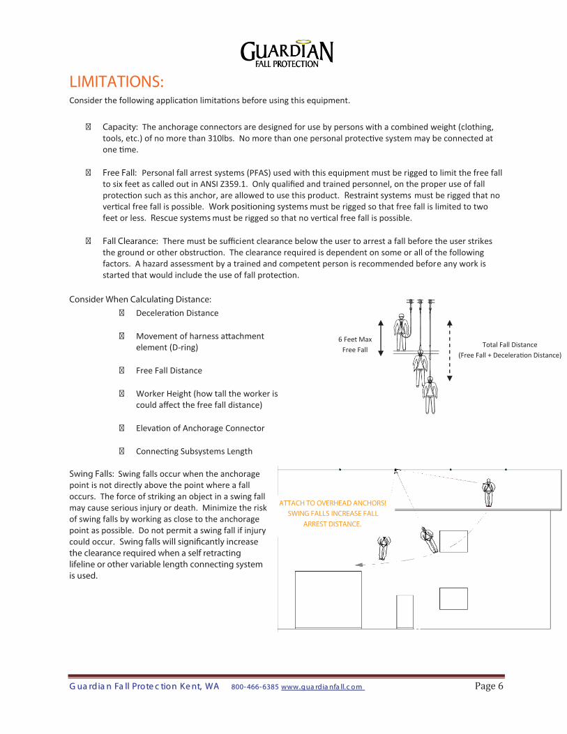
ATTACH TO OVERHEAD ANCHORS! SWING FALLS INCREASE FALL
ARREST DISTANCE.
LIMITATIONS: Consider the following application limitations before using this equipment.
� Capacity: The anchorage connectors are designed for use by persons with a combined weight (clothing, tools, etc.) of no more than 310lbs. No more than one personal protective system may be connected at one time.
� Free Fall: Personal fall arrest systems (PFAS) used with this equipment must be rigged to limit the free fall to six feet as called out in ANSI Z359.1. Only qualified and trained personnel, on the proper use of fall protection such as this anchor, are allowed to use this product. Restraint systems must be rigged that no vertical free fall is possible. Work positioning systems must be rigged so that free fall is limited to two feet or less. Rescue systems must be rigged so that no vertical free fall is possible.
� Fall Clearance: There must be sufficient clearance below the user to arrest a fall before the user strikes the ground or other obstruction. The clearance required is dependent on some or all of the following factors. A hazard assessment by a trained and competent person is recommended before any work is started that would include the use of fall protection.
Consider When Calculating Distance:
� Deceleration Distance
� Movement of harness attachment element (D-ring)
� Free Fall Distance
� Worker Height (how tall the worker is
could affect the free fall distance)
� Elevation of Anchorage Connector
� Connecting Subsystems Length Swing Falls: Swing falls occur when the anchorage point is not directly above the point where a fall occurs. The force of striking an object in a swing fall may cause serious injury or death. Minimize the risk of swing falls by working as close to the anchorage point as possible. Do not permit a swing fall if injury could occur. Swing falls will signi�cantly increase the clearance required when a self retracting lifeline or other variable length connecting system is used.
Total Fall Distance (Free Fall + Deceleration Distance)
6 Feet Max Free Fall
GG uuaa rrdd iiaa nn FFaa llll PPrroo ttee cc ttiioo nn KK ee nntt,, WWAA 880000-- 446666-- 66338855 wwwwww .. gg uuaa rrdd iiaa nnffaa llll.. cc oo mm Page 7
UUSSIINNGG TTHHEE VVEERRTTIICCAALL LLIIFFEELLIINNEE AASSSSEEMM BBLLYY: � Guardian Vertical Lifeline Assemblies, and Guardian Rope Assemblies with fall arrest components such as
Rope Grabs and positioning devices, are designed for use as a Personal Fall Protection System (PFAS). The equipment must be inspected before each use.
� Attach only to approved anchorages suited for the applications and meeting OSHA and any other
applicable standards.
� The maximum free fall distance allowed with this system is six (6) feet unless components are designed for extended free falls. The system is rated for 5,000 lbs., although is a shock absorber pack is incorporated in the system, the arrest forces on the body are limited to under 1,000 lbs. when properly used.
� The maximum worker weight, including tools, for use with this lifeline is 310 lbs.
� The Positioning Device is locked until the cam lever is depressed, which allows the unit to slide along the
rope. Once the worker is at their location, they can release the Positioning Device so that it locks onto the rope.
� DO NOT grab the Positioning Device in the event of a fall, accidentally depressing the cam lock can open
up the unit and cause it to slide on the rope.
� In order to work properly, the lanyard attached to the Positioning Device or Rope Grab must allow the device to engage on the rope in its intended locking method. Users should familiarize themselves with the Positioning Device before using.
� The shock absorber pack on the lifeline system, if your system has a shock absorber permanently attached
to the end of the rope, is designed for attachment at the anchor point. If the shock absorber is built into the leg of the rope grab, positioning device, or fall arrester, that portion must be attached to the user’s approved body harness.
� DO NOT tie knots in rope lifelines. Knots in rope significantly reduce the rope’s strength properties.
Limiter knots are permitted at the end of the system to limit the amount of Positioning Device travel.
CCOONNSSUULLTT WWIITTHH YYOOUURR DDOOCCTTOORR IISS TTHHEERREE IISS RREEAASSOONN TTOO DDOOUUBBTT YYOOUURR FFIITTNNEESSSS TTOO SSAAFFEELLYY AABBSSOORRBB TTHHEE SSHHOOCCKK FFRROOMM AA FFAALLLL AARRRREESSTT.. AAGGEE,, FFIITTNNEESSSS,, AANNDD HHEEAALLTTHH CCOONNDDIITTIIOONNSS CCAANN SSEERRIIOOUUSSLLYY AAFFFFEECCTT AA WW OORRKKEERR’’SS AABBIILLIITTYY TTOO WWIITTHHSSTTAANNDD FFAALLLLSS.. PPRREEGGNNAANNTT WWOOMM EENN OORR MM IINNOORRSS MM UUSSTT NNOOTT UUSSEE AANNYY GGUUAARRDDIIAANN FFAALLLL PPRROOTTEECCTTIIOONN EEQQUUIIPPMM EENNTT..
IMPORTANT!
GG uuaa rrdd iiaa nn FFaa llll PPrroo ttee cc ttiioo nn KK ee nntt,, WWAA 880000-- 446666-- 66338855 wwwwww .. gg uuaa rrdd iiaa nnffaa llll.. cc oo mm Page 8
PPRROOPPEERR UUSSEE: � The Positioning Device or Rope Grab fall arrester components must be adjusted during use to limit free
fall potential. Slack in the system can allow momentum to build that could generate a free fall of greater than six (6) feet. Always adjust the Positioning Device to minimize potential slack (free fall) in the system.
� Do not work above the Positioning Device unless free fall is limited to six (6) feet or less.
� Do not remove components from lifeline assemblies.
� The system is designed so that there is adequate fall distance, and a lower level cannot be contacted.
� System and application is designed to prohibit the potential for a swing fall if injury can occur.
� One person per vertical lifeline system.
LLAABBEELLSS::
This label must be present and legible onthe Vertical Lifeline Assembly at all times.
0
2
4
6
8
10
12
14
16
18
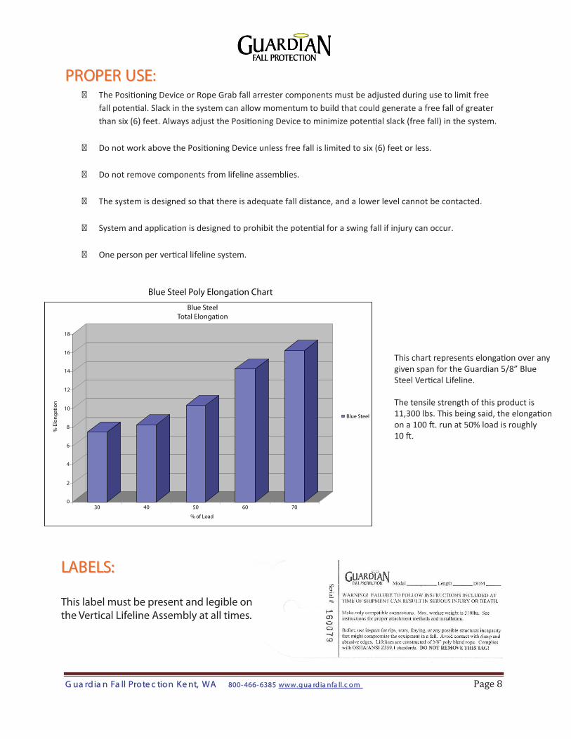
Blue Steel Poly Elongation Chart
Blue SteelTotal Elongation
% E
long
atio
n
Blue Steel
% of Load
30 40 50 60 70
This chart represents elongation over anygiven span for the Guardian 5/8” BlueSteel Vertical Lifeline.
The tensile strength of this product is11,300 lbs. This being said, the elongationon a 100 ft. run at 50% load is roughly10 ft.

GG uuaa rrdd iiaa nn FFaa llll PPrroo ttee cc ttiioo nn KK ee nntt,, WWAA 880000-- 446666-- 66338855 wwwwww .. gg uuaa rrdd iiaa nnffaa llll.. cc oo mm Page 9
IINNSSPPEECCTTIIOONN LLOOGG::
GGuuaarrddiiaann FFaallll PPrrootteeccttiioonn,, IInncc.. 800-466-6385
26609 79th Ave. S. Kent, WA 98032
www.guardianfall.com
USER MUST INSPECT EQUIPMENT BEFORE EACH USE. COMPETENT PERSON TO INSPECT AND INITIAL AT LEAST EVERY 6 MONTHS.
Date of First Use_________________
YR. J F M A M J J A S O N D
The Vertical Lifeline Assembly has a five-year expiration from the date of first use. A regular semi-annual inspection is required