VERTICAL ACTING GATES - autoquip.com · Never run the unit with the gates or doors open! The gates...
44
GATE & ENCLOSURE INSTALLATION MANUAL VERTICAL ACTING GATES P.O. Box 1058 • 1058 West Industrial Avenue • Guthrie, OK 73044-1058 • 888-811-9876 • 405-282-5200 • FAX: 405-282-3302 • www.autoquip.com Item # 830VG Version 2.0 09/2007
Transcript of VERTICAL ACTING GATES - autoquip.com · Never run the unit with the gates or doors open! The gates...

GATE & ENCLOSURE INSTALLATION MANUAL
VERTICAL ACTING GATES
P.O. Box 1058 • 1058 West Industrial Avenue • Guthrie, OK 73044-1058 • 888-811-9876 • 405-282-5200 • FAX: 405-282-3302 • www.autoquip.com
Item # 830VG Version 2.0
09/2007

2
TABLE OF CONTENTS Introduction 3
Inspection & Identification 4
Pre-Installation Site Visit 5
Responsibility of Owners/Users 6
Safety Signal Words 7
Safety Practices 8
Label Placement 10
Gate Installation Instructions 12
Enclosure Installation Instructions 35
Operating Instructions 38
Routine Maintenance 40
Replacement Parts List 41
Troubleshooting Analysis 42
Warranty 44
IMPORTANT Please read and understand this manual prior to operation. If any questions should arise, call a local representative or Autoquip Corporation at 1-888-811-9876 or 405-282-5200.
PLANNED MAINTENANCE PROGRAM
A local Autoquip representative provides a Planned Maintenance Program (PMP) for this equipment using factory-trained personnel. Call a local representative or Autoquip Corporation at 1-888-811-9876 or 405-282-5200 for more information.

3
INTRODUCTION Autoquip Corporation has designed and manufactured these gates and enclosures to conform to ASME B20.1 – Safety Standard for Conveyors and Related Equipment in order to provide personnel protection from moving loads on the lift and to ensure safe access to the lift at every operating level. They have been built to provide many years of dependable service and proper installation of this equipment is vital to personnel safety. It is vital for the installers to read and understand this manual! These instructions have been prepared and organized to assist the installers and it is important for these individuals to carefully follow the steps in the order they are presented! Situations may arise which are not covered in these installation instructions. If you have questions, please call Autoquip Customer Service at (405) 282-5200 or 1-888-811-9876. NOTE: Unless otherwise stated, mechanical installation does not include unloading, permits, seismic calculations, or extensive acceptance testing. The requirements of each contract should be carefully reviewed for possible conflicts of interpretation.

4
INSPECTION & IDENTIFICATION The following items are typically shipped loose within each manually operated Vertical Gate order: A. (2) Gate Posts with Cables, Pulleys and Interlock Mounting Plates B. (1) Gate Header Angle with mounting holes C. (1) or (2) Expanded Metal Gate Panels (depending on style) D. Interlock Kits E. Misc. Gate Mounting Hardware, Manual, and Signs/Labels F. Varies – Expanded Metal Enclosure Panels per General Arrangement Drawing G. Varies – Enclosure Panel Mounting Teck-Screws, Top Caps, Corner Angles Powered Gate orders include additional pieces, including: H. Drive, Bearings, Shaft with Sprockets I. Operator Controls J. Lifting Chains K. Upper and Lower Travel Limit Switch Kits L. Miscellaneous Mounting Hardware NOTE: The “Bill of Lading” will state the number of pieces shipped. TWO ITEMS MAY BE BANDED TOGETHER AND COUNT AS ONE PIECE. Upon receipt of the shipment, check for exposed damage or shortages and make note of it on the trucking company Bill of Lading or the Shipping Papers. Reports of concealed damage to items contained in crates must be reported within 48 hours. DO NOT destroy the crating while opening it to inspect the contents. If damage is suspected or found, report it directly to the carrier. DO NOT contact Autoquip Corporation!! All shipments are FOB from the Autoquip plant. Any claims for damage must be filed with the carrier. Any parts shipped from Autoquip that are intended to replace damaged or lost items will be invoiced to the ordering party. Assuming no damage has occurred to the crate, check the components against the packing list. This will provide assurance that every item shipped has been received. Everything needed for the installation should be available. If not, report any shortages to Autoquip Corporation within 10 days. (Autoquip is not responsible for parts lost, stolen or damaged during transportation, storage, installation, or during any other circumstances or conditions that may be beyond corporate control.) Before beginning the installation process, look at the skid that the gates and enclosures arrived on. Check for any damage and compare the packing list to the gates and enclosures to ensure that everything is on hand. If there are any missing pieces, contact Autoquip Product Support Team at (405) 282-5200.
5
PRE-INSTALLATION SITE VISIT SITE CONDITIONS Whenever possible, make a pre-installation visit or call someone at the site. Installers must be familiar with everything relative to proper installation of this equipment. Some concerns are listed below, though listing every affecting contingency is impossible. It is the installer’s responsibility to check the site for problems and work out solutions with the appropriate people. Some of the areas of concern are: 1. Is the site accessible? 2. Can the equipment get through the existing doorways, halls, and shaft openings? 3. How will the unit be raised, set into position, and accessed? 4. Can a chain fall be hooked to an available overhead support? 5. Is there a forklift available? 6. Is bracing required?
7. Look for problem areas such as bracing and overhead interference from ducts,
joists, and pipes. It is always best to be prepared, so do as much pre-planning as possible before the installation procedure actually begins. Learn about the site, the equipment, and the installation process.

6
RESPONSIBILTY OF OWNERS/USERS CODE COMPLIANCE Ultimate responsibility for gaining state and local code approval is the responsibility of the buyer of the VRC. Please acquaint yourself with the permitting and/or licensing expenses and requirements of the local regulatory agencies in the installation area. . INSPECTION & MAINTENANCE The gates & enclosures shall be inspected & maintained in proper working order in accordance with Autoquip’s operating/maintenance (O&M) manual and with other applicable safe operating practices. REMOVAL FROM SERVICE Any gate not in safe operating condition such as, but not limited to, missing parts or fasteners, any bent or cracked structural members, cut or frayed electric lines, damaged or malfunctioning controls or safety devices, etc. shall be removed from service until it is repaired to the original manufacturer’s standards. REPAIRS All repairs shall be made by qualified personnel in conformance with Autoquip’s instructions. OPERATORS Only trained and authorized personnel shall be permitted to operate the lift and gate. BEFORE OPERATION Before using the lift and gate, the operator shall have:
• Read and/or had explained, and understood, the manufacturer’s operating instructions and safety rules.
• Inspected the lift for proper operation and condition. Any suspect item shall be carefully examined and a determination made by a qualified person as to whether it constitutes a hazard. All items not in conformance with Autoquip’s specification shall be corrected before further use of the lift.
DURING OPERATION The lift and gate shall only be used in accordance with Autoquip’s O&M manual.
• Do not overload the lift. • Ensure that all safety devices are operational and in place.
MODIFICATIONS OR ALTERATIONS Modifications or alterations to this equipment shall be made only with written permission of Autoquip. Autoquip does not foresee and does not anticipate unauthorized modifications, and these changes or alterations are grounds for voiding all warranties.

SAFETY SIGNAL WORDS SAFETY ALERTS (Required Reading!)
The following SAFETY ALERTS are intended to create awareness of owners, operators, and maintenance personnel of the potential safety hazards and the steps that must be taken to avoid accidents. These same alerts are inserted throughout this manual to identify specific hazards that may endanger uninformed personnel. Identification of every conceivable hazardous situation is impossible. Therefore, all personnel have the responsibility to diligently exercise safe practices whenever exposed to this equipment. ____________________________________________________________
DANGER!
Identifies a hazardous situation which, if not avoided, will result in death or severe personal injury. _____________________________________________________________
WARNING! Identifies a hazardous situation which, if not avoided, could result in death or serious personal injury.
CAUTION! Identifies a hazardous situation which, if not avoided, may result in minor or moderate personal injury. _____________________________________________________________
CAUTION!
Caution used without the safety alert symbol indicates a potentially hazardous situation which, if not avoided, may result in property or equipment damage.
7SAFETY PRACTICES

8
ngerous”!
DANGER! High voltage! May cause personal injury or death. Repairs should only be performed by a qualified service/control technician!!
DANGER!
Qualified personnel only!! Only qualified service personnel should perform procedures labeled as “da
DANGER!
Be sure of equipment stability! To avoid personal injury or death, check for stability. If the supports seem unstable, do not operate! Contact Autoquip immediately!
DANGER!
Turn off power! To avoid personal injury or death, be sure
the power is off and is locked out per OSHA Lock-Out, Tag-Out procedures!
DANGER!
Practice field safety procedures! To avoid personal injury or death, utilize all applicable precautions for steel erection and equipment assembly in addition to OSHA regulations for lock-out, tag-out, etc.!

9
WARNING!
SAFETY PRACTICES
Support all posts and components! Illustrations in this manual may show them unsupported. This is done in order to make the equipment and its installation clearly understood. Be sure to properly secure all lift beams and components on the actual unit!
WARNING!
Never run the unit with the gates or doors open! The gates must not open when the lift is in operation or when the platform is not present. Should this condition exist, the interlock circuit is not functioning properly due to incorrect installation of, or damage to, status switches and/or interlocking components. This condition must be corrected immediately. Failure to correct this condition may result in serious injury or death.
WARNING!
Never operate unit when parts are defective! Do not operate this equipment when substandard or defective parts are in use! Contact an Autoquip Service Representative to rectify all such situations.
CAUTION! Do not run powered gate until limit switches are set! If the electrical work is not complete, do not run the gate to full up or full down positions until the limits are set.
CAUTION! Cables must be seated before raising gate! Be sure the cables are seated in the overhead pulleys prior to raising the gate.
10
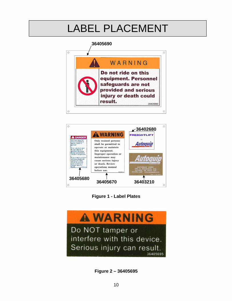
LABEL PLACEMENT
36402680
36405690
36405680 36405670 36403210
Figure 1 - Label Plates
Figure 2 – 36405695

11
LABEL PLACEMENT
Additional 36405680 Decal installed on Gate Post, Same
side as the Push-Button Station
Decal Plates shown in Figure 1 should be attached to gate in this area with hardware provided
Locate 36405695
near Status Switch
Figure 4 - Label Placement

12
INSTALLATION INSTRUCTIONS
ITEMS TO BE SUPPLIED BY THE INSTALLER
• 3/8” x 3 ½” (minimum) Anchor Bolts (8 per gate) • Miscellaneous support bracing (angle or channel) as required
TOOL REQUIREMENTS
safety glasses hard hat (if job requires)
Allen wrenches to 3/8” screws
5/16” hex head driver bit for TEK hammer
“C” clamps hammer drill
carpenter square 4’ level
chalk line 25’ tape measure
4” angle grinder slip joint pliers
drift punches open end wrench set to 3/4"
drill bits to 3/8” screw driver sets (flat and Phillips)
electric drill socket set, 1/4” and 3/8” drives
hack saw (or port-a-band) taps and tap wrench to 3/8”
extension cords welding equipment
Other items to consider are:
• Cables/chain with 1000 lb lifting capacity
• Chain fall or come-a-long
• Fork lift
• Sledge hammer
13
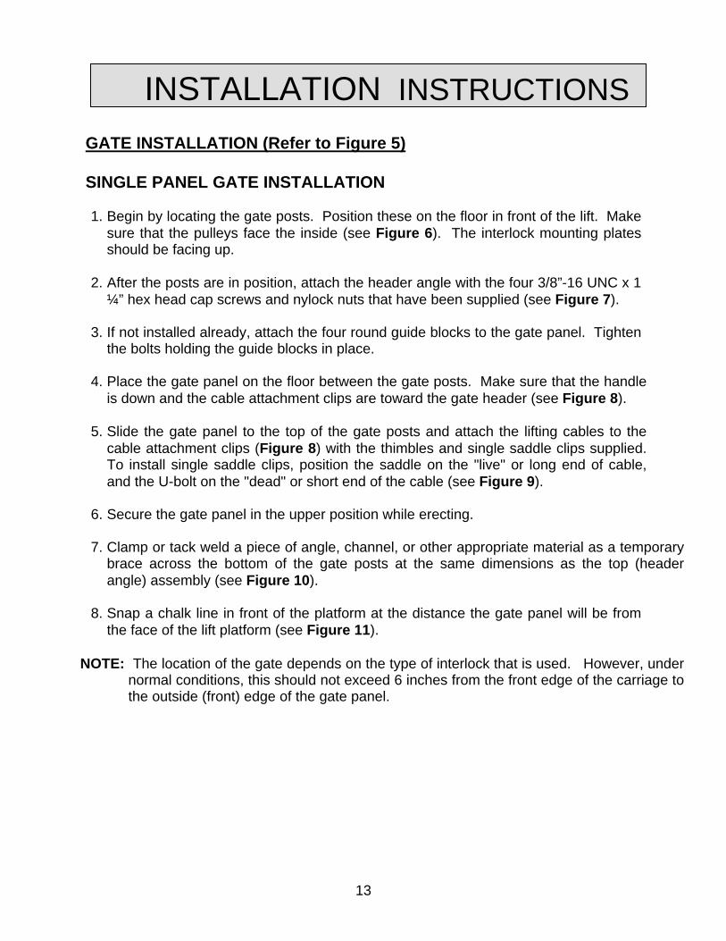
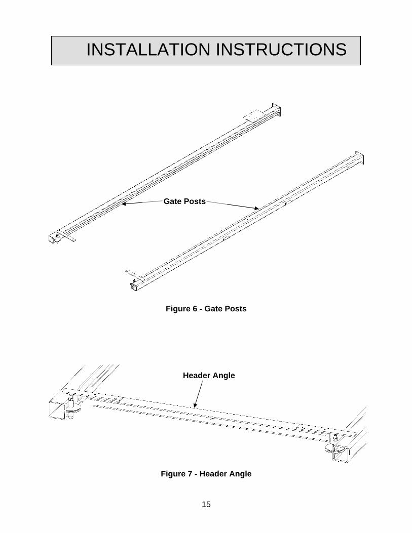
INSTALLATION INSTRUCTIONS GATE INSTALLATION (Refer to Figure 5) SINGLE PANEL GATE INSTALLATION 1. Begin by locating the gate posts. Position these on the floor in front of the lift. Make
sure that the pulleys face the inside (see Figure 6). The interlock mounting plates should be facing up.
2. After the posts are in position, attach the header angle with the four 3/8”-16 UNC x 1
¼” hex head cap screws and nylock nuts that have been supplied (see Figure 7). 3. If not installed already, attach the four round guide blocks to the gate panel. Tighten
the bolts holding the guide blocks in place. 4. Place the gate panel on the floor between the gate posts. Make sure that the handle
is down and the cable attachment clips are toward the gate header (see Figure 8).
5. Slide the gate panel to the top of the gate posts and attach the lifting cables to the cable attachment clips (Figure 8) with the thimbles and single saddle clips supplied. To install single saddle clips, position the saddle on the "live" or long end of cable, and the U-bolt on the "dead" or short end of the cable (see Figure 9).
6. Secure the gate panel in the upper position while erecting. 7. Clamp or tack weld a piece of angle, channel, or other appropriate material as a temporary
brace across the bottom of the gate posts at the same dimensions as the top (header angle) assembly (see Figure 10).
8. Snap a chalk line in front of the platform at the distance the gate panel will be from
the face of the lift platform (see Figure 11).
NOTE: The location of the gate depends on the type of interlock that is used. However, under normal conditions, this should not exceed 6 inches from the front edge of the carriage to the outside (front) edge of the gate panel.
14
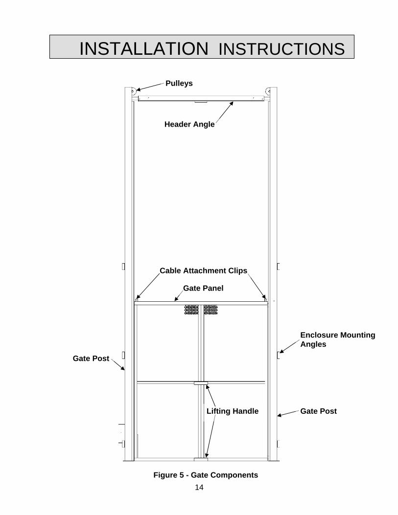
INSTALLATION INSTRUCTIONS
Pulleys
Header Angle
Figure 5 - Gate Components
Gate Panel
Cable Attachment Clips
Enclosure Mounting Angles
Gate Post
Lifting Handle Gate Post
15
INSTALLATION INSTRUCTIONS
Gate Posts
Figure 6 - Gate Posts
Header Angle
Figure 7 - Header Angle

16
INSTALLATION INSTRUCTIONS
Cable Attachment Clip
UHMW Guide Blocks
Panel
Figure 8 - Cable Attachment Clip
Thimble
Figure 9 – Lifting Cable Attachment

17
INSTALLATION INSTRUCTIONS
Temporary Brace
Figure 10 - Temporary Bracing
Figure 11 - Floor Layout
18
INSTALLATION INSTRUCTIONS
WARNING!
Counterweighted gate posts are heavy. Use caution when raising them into position.
CAUTION!
Make sure that all cables are attached to the gate panel and that the gate panel is secured in the up position. Failure to do so could result in the gate panel lowering rapidly, causing equipment damage or personal injury.
11. Carefully raise the gate assembly with the door handle facing away from the lift
platform. Move it into position. 12. Plumb each post. 13. Verify gate post locations with respect to lift carriage, as well as spacing between
posts, then anchor each post with four 3/8” concrete anchors at least 3 ½” long. The installer supplies these bolts. (It may help to use only two of the four anchors until all work is done.)
14. Remove the counterweight retaining bolt from each post. These are located
approximately 72” from the bottom of the gate post. 15. Carefully release the gate panel and lower into position. Verify that the gate is
properly counterbalanced. Do this by opening and closing the gate. It should move easily and smoothly.
16. After determining proper operation, weld additional support bracing in place and
complete the anchoring of the gate posts. NOTE: Make sure that the supports do no interfere with any portion of the lift
platform, wheel blocks, or means of lifting. 17. Install the interlocks according to the Interlock Installation instructions in the next
section.
18. Install the warning decals on the gate panel and post (see Label Placement section).

19
INSTALLATION INSTRUCTIONS BI-PANEL GATE INSTALLATION (Refer to Figure 12)
The installation of the bi-panel vertical acting gate is the same as the single panel gate, with the following three exceptions:
• There will be two counterweighted posts welded together for each gate.
• There will be two gate panels; one upper panel and one lower panel.
• The header angle will be attached on the lift side, with the header angle facing away from the lift.
The upper panel is the FRONT panel. As the gate is assembled on the floor, the upper panel will be placed in the lower guide channel (the one closest to the floor). The LOWER panel will be placed in the top set of guide channels. The lower panel will be the only panel that will have Unistrut channels for the interlock status switch activating cam and/or the interlock strike. Use the installation instructions for a single panel vertical acting gate as a guide line. RAMP OPTION 1. When a ramp is used, the gate will need additional space from the bottom of the
gate panel to the floor in order for the ramp will clear. 2. Position the front edge (highest edge) of the ramp 1” from the edge of the lift
platform. 3. Secure the ramp in position using concrete anchor bolts (expansion) at each
mounting tab. The installer supplies these bolts.

20
INSTALLATION INSTRUCTIONS
Pulleys
Header Angle
Cable Attachment Clips
Upper (Front) Panel
Lifting Handles Lower (Back)
Panel
Figure 12 - Bi-Panel Gate Components
21
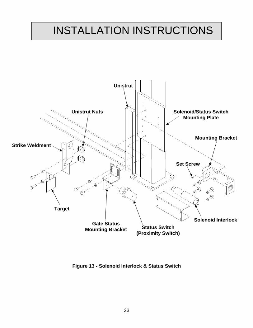
INSTALLATION INSTRUCTIONS INTERLOCK INSTALLATION INSTRUCTIONS There are two kinds of interlocks that can be used on vertical gates, depending on the application and/or local codes. Determine which style of interlock that will be installed before proceeding further. SOLENOID INTERLOCK (Refer to Figure 13)
WARNING!
Never run the unit with the gates or doors open! The gates must not open when the lift is in operation or when the platform is not present. Should this condition exist, the interlock circuit is not functioning properly due to incorrect installation of, or damage to, status switches and/or interlocking components. This condition must be corrected immediately. Failure to correct this condition may result in serious injury or death.
DANGER!
Qualified personnel only!! Only qualified service personnel should perform procedures labeled as “dangerous”!
The solenoid interlock can be used on both single and bi-panel vertical acting gates. Installation of the interlock and the gate status switch are to be accomplished after the gate has been erected and secured in position. 1. After checking the gate for proper operation, attach the solenoid mounting bracket to
the mounting plate on the gate post with four ¼” –20 UNC screws that have been supplied as shown.
2. Make sure that the solenoid is secure in the set collar, being seated fully against the
shoulder of the bracket. CAUTION!
Do not over tighten. Over tightening the set screw will inhibit solenoid bolt operation.
22
INSTALLATION INSTRUCTIONS 3. Mount the strike weldment and gate status switch target to the Unistrut channel
using the ¼”-20 UNC Unistrut nuts and the ¼”-20 UNC screws that have been supplied as shown.
4. With the gate panel in the fully closed position, adjust the strike so that the solenoid
“bolt” is centered in the strike hole. NOTE: The solenoid interlock “bolt” has a ½” throw. Adjustment is critical. 5. Using the two ¼”-20 screws that have been supplied, mount the gate status switch
mounting bracket to the status switch mounting plate on the gate post as shown. 6. All solenoid interlocks must be fail-secure. This means that in the event of a power
failure, the gate must remain locked until the power is restored and lift platform is at the same level as the gate.
7. With the gate panel in the fully closed position, adjust the strike weldment, the
proximity switch, and proximity switch target so that the switch contacts are closed when the interlock bolt engages the one-inch hole in the strike weldment. Adjust status switch target so that interlock engages only within desired range of 1” hole in strike weldment.
NOTE: Adjustments allow both the switch and target to be moved. A one inch
horizontal distance must be maintained between the faces of the proximity switch and target to ensure proper functionality.
23
INSTALLATION INSTRUCTIONS
Unistrut Nuts
Set Screw
Solenoid/Status Switch Mounting Plate
Mounting Bracket
Solenoid Interlock Status Switch
(Proximity Switch)
Gate Status Mounting Bracket
Unistrut
Strike Weldment
Target
Figure 13 - Solenoid Interlock & Status Switch

24
INSTALLATION INSTRUCTIONS WIRING INFORMATION FOR SOLENOID
• The solenoid requires 24-volt DC power. Applications of other power sources will result in sever damage to the interlock.
• The DC power is obtained through the use of a rectifier that is supplied in the
electrical control enclosure.
• The proper solenoid connections for 24-volt DC operation are to connect the RED and WHITE leads from the solenoid to the correct terminals in the electrical control enclosure.
• The BLACK and BLUE leads of the solenoid must be wired together.
• See Figure 14 for wiring diagram.
DANGER!
Qualified personnel only!! Only qualified service personnel should perform procedures labeled as “dangerous”!

25
INSTALLATION INSTRUCTIONS
Figure 14 - Interlock Wiring

26
INSTALLATION INSTRUCTIONS
C.J. ANDERSON INTERLOCK HG1 INSTALLATION (Refer to Figure 15) The HG-1 interlock can be used at any level. It is important that the actuating roller be properly adjusted so that that the actuating cam does not cause the actuating roller on the interlock to over travel. 1. After the gate has been erected and tested for proper operation, the interlock can be
installed. 2. Mount the interlock to the gate post using the three 1/4”-20 UNC screws that have
been supplied as shown. 3. Mount the HG-1 strike weldment, attached to the gate panel, to the Unistrut channel
with two ¼”-20 UNC screws and the Unistrut nuts. Adjust the strike so that it is seated in the interlock body and held in place when the actuating roller arm is in its normal forward position. It is also necessary that the HG-1 strike weldment actuates the switch arm to close the contact switch in the bottom of the HG-1 interlock.
4. Mount the actuating cam to the lift platform railing so that it moves the actuating
roller back into position to release the HG-1 strike weldment. NOTE: When positioning the cam on the railing, do not allow the cam to interfere with
any objects during the full travel of the lift. 5. When the proper position is established, clamp or tack weld the cam in place. 6. Verify the operation of the cam, actuating roller, and the HG-1 strike weldment when
the lift platform moves to and from each level. NOTE: The HG-1 strike weldment must activate the contact switch when the gate is
closed. Failure to activate the contact switch will prevent the lift from operating. 7. After assuring proper operation, weld the actuating cam into its final position. 8. Repeat this procedure for all levels using this type of interlock. NOTE: This style of interlock does not need a gate status switch. The contact switch in
the HG-1 is the gate status switch.

27
INSTALLATION INSTRUCTIONS
Interlock Strike
Mounting Plate
Bottom of Gate Panel
Cam
Handrail Vertical Post Interlock,
Type HG1, RH
Gate Post
Adjustable Roller Arm
Rubber Roller
Carriage Platform
Figure 15 - HG1 Mechanical Interlocks
28
INSTALLATION INSTRUCTIONS
WARNING!
Never run the unit with the gates or doors open! The gates must not open when the lift is in operation or when the platform is not present. Should this condition exist, the interlock is not functioning properly due to incorrect installation or damage. This condition must be corrected immediately. Failure to correct this condition may result in serious injury or death.
HG-1 WIRING INFORMATION
• The contact block is wired in series between the terminals specified on the electrical schematic.
DANGER!
Qualified personnel only!! Only qualified service personnel should perform procedures labeled as “dangerous”!

29
INSTALLATION INSTRUCTIONS POWER GATE OPTION (Refer to Figures 16 & 17) These instructions are to be used in conjunction with the previous instructions for non-power vertical acting gates. The major differences are as follows:
• The location of the guide channel
• The use of chain and sprockets for lifting the gate panel
• The configuration of the post tops to accommodate the drive shaft. Gates smaller than eight feet in overall width can be assembled on the floor in front of the lift and raised as a single unit as with the non-powered gate. NOTE: Prior to standing the gate posts, make sure that the lift chains are secured to prevent them from falling into the gate post tube. 1. Position the gate posts in front of the lift with the guide channels down and the
channel openings toward each other. 2. Attach the header to the gate posts. NOTE: One or more center support bearings are provided depending on the gate
width. Generally gates less than eight feet overall will only have one center support bearing.
3. Attach the flange bearing side plate to the outside of the gate post. The flange
bearing should be mounted away from the chain sprocket. 4. Mount the motor and reducer to the mounting plate with ¼”-20 UNC screws that
have been supplied. 5. Position the gate panel in the guide channels and slide it to the top of the gate posts.
The top of the gate panel has a chain attachment lug welded to the top of the panel. Secure the gate panel in the upper position while lifting into position.

30
INSTALLATION INSTRUCTIONS
Gate Panel
Enclosure Mounting Angle
Gate Post
Gate Post
Header Angle
FIGURE 16 - Powered Gate Components

31
INSTALLATION INSTRUCTIONS
Motor
Reducer Flange Bearing
Counterweight Tubing
Guide Post Channel
Chain Sprocket
Drive Shaft
Master Link
Gate Panel
Header Angle
FIGURE 17 - Drive Detail

32
INSTALLATION INSTRUCTIONS
6. Place the chain over the drive shaft from back to front. Guide the chain down the gate post channel and attach the chain to the gate panel using the master link provided. Attach the other end of the chain to the counterweight and guide down the counterweight tubing.
NOTE: Each chain should have an equal number of links between the sprocket top
dead center and the gate panel attachment lug. 7. Clamp or tack weld a piece of angle, channel or other appropriate material as a
temporary brace across the bottom of the gate posts at the same dimensions as the top (header angle) assembly.
8. Snap a chalk line in front of the platform at the distance the gate panel will be from
the face of the lift platform. Under normal conditions this should not exceed 6 inches from the front edge of the carriage to the outside (front) edge of the gate panel.
CAUTION!
Make sure that all chains are attached to the gate panel and that the gate panel is secured in the up position. Failure to do so could result in the rapid lowering of the gate panel and possible equipment damage or personal injury.
9. Carefully raise the gate assembly. Move it into position. 10. Plumb each post. 11. Verify gate post locations with respect to lift carriage, as well as spacing between
posts, then anchor each post with four 3/8” concrete anchors at least 3 ½” long. The installer supplies these bolts. (It may help to use only two of the four anchors until all work is done.)
33
INSTALLATION INSTRUCTIONS 12. After determining proper operation, weld additional support bracing in place and
complete the anchoring of the gate posts. NOTE: Make sure that the supports do no interfere with any portion of the lift
platform, wheel blocks, or means of lifting. 13. Mount both the upper and lower limit switches to the rear of the post tubes (see
Figure 18). The switch arms must be rotated 90 degrees so they will contact the switch cam mounted to the gate panel.
14. With the ¼”-20 UNC screws and the Unistrut nuts, mount the switch activation
cam(s) to the Unistrut channel(s) mounted to the gate panel (see Figure 18). 15. When the electrical hook-up is complete, test the gate for operation and adjust the
torque limiter so that it will slip whenever the gate panel is either fully up or fully down and power has not been interrupted by the upper or lower limit switch(s).
NOTE: The lift MUST NOT operate unless the gate(s) are closed and the gate MUST
NOT operate unless the lift is at the same floor level as the gate which is to be opened.
16. Install enclosure panels (if required).

34
INSTALLATION INSTRUCTIONS
Limit Switch Bracket
Ustrut Nut
Ustrut Nut Switching Arm
Strike Mounting Ustrut
Limit Switch Mounting Ustrut
Strike
Limit Switch
FIGURE 18 – Upper and Lower Limit Switch Mounting
35
INSTALLATION INSTRUCTIONS ENCLOSURE PANELS Look at the plan views on the lift General Arrangement drawing to see the basic layout of the panels. Compare the enclosure panel length measurement to the drawing. If the lift approval drawing calls for full height enclosures, follow these drawings for assembly of the full height enclosures. The easiest way to assemble the enclosure panels is to start at one side of the gate and work around the lift. NOTE: If space allows, assemble a side first, and then stand the completed side up.
NOTE: The enclosure panels that attach to the floor will have “feet” for lagging them to the floor. For ease of installation, do not lag the enclosures until all of the enclosures have been assembled. 1. Find the first panel that goes on the right side of the gate. This will most likely be a
filler panel. Use TEK screws to attach the panel to the gatepost angle clips.
2. The next panel will connect to the first panel. In most cases, this will be a corner.
Use three 3” long corner angles and TEK screws to attach panels at the corner (see Figure 19).
3. Butt the panels together on the sides and attach through the enclosure angles, using
TEK screws. 4. Continue around the lift until the enclosures have been completed. 5. Mount the 12” long top cap splice across the top of the enclosure panel and attach
using TEK screws (see Figure 20).
6. Brace the enclosure back to the lift. The installer supplies this bracing. When
installing the bracing, make sure that it does not interfere with any moving components of the lift or gates.
7. Lag all of the mounting feet on the enclosures to the floor.
8. Mount the interlocks according to the instructions (see Interlock Installation section.)

36
INSTALLATION INSTRUCTIONS
Corner Angle
Figure 19 - Corner Angles

37
INSTALLATION INSTRUCTIONS
Top Cap Splice
Figure 20 - Top Cap Splice

38
OPERATING INSTRUCTIONS
POWERED GATES
DANGER!
To avoid personal injury or death, do not operate this equipment with substandard, defective, or missing parts. Contact a local Autoquip service representative if a deficiency is found.
WARNING!
Never run the unit with the gates or doors open! The gates must not open when the lift is in operation or when the platform is not present. Should this condition exist, the interlock is not functioning properly due to incorrect installation or damage. This condition must be corrected immediately. Failure to correct this condition may result in serious injury or death.
Powered vertical gates are electromechanically driven in both directions using UP/DOWN operator controls. UP When the UP button is pressed or drop cord pulled, the brake motor is started and the gearbox output shaft rotates the chain sprockets. The gate chains go over these sprockets and then attach to counter weights. As the motor rotates, the output shaft turns and raises the gate, provided the motor rotation is correct. If the gate does not move, check the motor rotation and correct if necessary. The gate will continue to move upward as long as the button or cord is held. When the gate panel reaches the upper travel limit switch, the motor will stop and the motor brake will be applied.

39
OPERATING INSTRUCTIONS
CAUTION!
Do not run gate until limits are set! Never run the gate to the full up or full down positions without limit switches in place and in working order.
When the motor stops, the electric brake on the motor will de-energize and lock the motor drive, thus holding the gate panel in the raised position. DOWN Pressing the DOWN push-button will cause the reversing motor starter to engage and start the motor. The gate will travel down until tripping the down limit switch. This turns off the motor and the motor brake applies.

40
ROUTINE MAINTENANCE
DANGER!
To avoid personal injury or death, all maintenance procedures described in this section should only be performed by qualified service personnel.
DANGER!
To avoid personal injury or death, do not operate this equipment with substandard, defective, or missing parts. Contact a local Autoquip service representative if a deficiency is found.
WARNING!
To avoid serious injury or death, GUARDS, INTERLOCKS, and SAFETY DEVICES must be restored to correct operation when installing parts or making repairs.
1. Listen for unusual noises. Isolate and check for the cause. Repair if required. 2. Check gate status limit switches for proper operation and adjust if needed. 3. Check interlocks for proper operation and adjust as needed. 4. Check for broken or cracked welds. 5. Check that all anchors are in place and secure. 6. Check the cables, pulleys, and cable clamps for unusual wear (manual gates) 7. Check the chains, sprockets, and master links for unusual wear (powered gates). 8. Look for any unusual rub marks on the guides, gate panel, etc, which might indicate
misalignment of the components due to damage or something out of tolerance.

41
REPLACEMENT PARTS LIST Specific part numbers vary from job to job, depending on the model and options chosen for the application. Call the Autoquip Service Department at (405) 282-5200 or 1-888-811-9876 with the serial number of the specific FREIGHTLIFT equipment to order the appropriate parts.

42
DANGER!
Troubleshooting and maintenance on the lift should only be performed by qualified service technicians!!
PROBLEM POSSIBLE CAUSE AND SOLUTION Powered Gate will not raise or lower (motor not running or “humming”). .
• The main line disconnect switch is open (off). Check and close.
• The main distribution panel circuit breaker is tripped or a fuse is blown. Check and reset or replace as necessary.
• The main line fuse disconnect fuse is blown. Check and replace.
• The “UP” push button or circuit is malfunctioning. Check at the other push button station for “UP” function. Check components and circuit. Repair or replace.
• The motor starter overloads (M10L) have tripped. Check and reset. If it trips again, check for cause in the motor circuit.
• The control transformer fuse is blown. Check and replace.
• The motor starter coil (MI) has burned out. Check and replace. (Will usually blow the control transformer fuse.)
• The limit switch tripped or is malfunctioning, preventing the “UP” command. Check with the lift at a lower level on stops.
TROUBLESHOOTING ANALYSIS

43
PROBLEM POSSIBLE CAUSE AND SOLUTION Gate does not raise or lower (motor is running or humming on powered gates)
• The lifting chains may be disconnected or off their sprockets. Check and correct as necessary.
• Rotation on the 3-phase motor may be reversed. Reverse any two motor electrical leads.
• The 3-phase motor may be single-phasing (humming). Check wiring, fuses, etc.
• The voltage at the motor terminals may be too low to run the motor with the existing load. Check by measuring the voltage at the motor terminals (or as near as possible) while the motor is running under load. Inadequate or incorrect wiring can starve the motor when the source voltage is ample. Correct as necessary.
• The motor brake may be seized if the motor is humming, blowing fuses, or overloads. Remove the motor and check to see if the brake is working correctly.
Powered Gate Motor labors or heats excessively.
• The voltage may be low. Check at the motor terminals while the motor is running under load. Inadequate wiring can starve the motor even when the source voltage is ample.
• The wiring may be incorrect. Be sure one leg of the motor line is not connected to the ground prong. This can happen particularly on 3-phase units using twist-lock plugs.
• The gear reducer may be binding from oil starvation. This can cause high internal heat. The gear reducer can be irreparably damaged by oil starvation and may have to be replaced!
Powered Gate operates in a “spongy” or jerky fashion.
• The chain sprockets may be binding. Check and repair
• The chain may be off of a sprocket. Check and repair.
• The gate panel may be binding in the guide ways. Check and repair.
TROUBLESHOOTING ANALYSIS
44
LIMITED WARRANTY
The user is solely responsible for using this equipment in a safe manner and observing all of the safety guidelines provided in the Owner’s Manual and on the warning labels provided with the lift. If you are unable to locate either the manual or the warning labels, please contact Autoquip or access www.autoquip.com for replacement downloads or information. Autoquip Corporation expressly warrants that this product will be free from defects in material and workmanship under normal, intended use for a period of One (1) Year for all electrical, mechanical, and hydraulic components, parts or devices. Ninety (90) days Labor warranty, extended to One (1) year with a Planned Maintenance Contract in place. Autoquip Corporation also warrants the structure of the lift against breakage or failure for a period of Five (5) years. The warranty period begins from the date of shipment. When making a claim, immediately send your dealer or Autoquip notice of your claim. All claims must be received by Autoquip within the warranty time period. The maximum liability of Autoquip, under this Limited Warranty, is limited to the replacement of the equipment. This warranty shall not apply to any Autoquip lift or parts of Autoquip lift that have been damaged or broken in transit/shipping, or due directly or indirectly to misuse, abuse, vehicle impact, negligence, faulty installation, fire, floods, acts of God, accidents, or that have been used in a manner contrary to the manufacturer’s limitations or recommendations as stated in the manual, or that have been repaired, altered or modified in any manner outside of Autoquip Corp’s manufacturing facility or which have not been expressly authorized by Autoquip. Autoquip Corporation makes no warranty or representation with respect to the compliance of any equipment with state or local safety or product standard codes, and any failure to comply with such codes shall not be considered a defect of material or workmanship under this warranty. Autoquip Corporation shall not be liable for any direct or consequential damages resulting from such noncompliance. Autoquip Corporation’s obligation under this warranty is limited to the replacement or repair of defective components at its factory or another location at Autoquip Corp’s discretion at no cost to the owner. This is owner’s sole remedy. Replacement parts (with exception of electrical components) will be warranted for a period of ninety (90) days. Except as stated herein, Autoquip Corporation will not be liable for any loss, injury, or damage to persons or property, nor for direct, indirect, or consequential damage of any kind, resulting from failure or defective operation of said equipment. All parts used to replace defective material must be genuine Autoquip parts in order to be covered by this Limited Warranty. .
AUTOQUIP CORP P.O. Box 1058, Guthrie, OK 73044-1058 Telephone: (888) 811-9876 · (405) 282-5200 Fax: (405) 282-8105 www.autoquip.com