
Vertical Access Ladder System Page...Installation Vertical Access Ladders - System Install Guide...
12
Vertical Access Ladder System Operation & Maintenance Manual
Transcript of Vertical Access Ladder System Page...Installation Vertical Access Ladders - System Install Guide...

Vertical Access Ladder SystemOperation & Maintenance Manual

General Description
Our vertical access ladder systems are supplied in a fully customisable modular kit that can be assembled and constructed on site, safely and efficiently. This system has been designed and manufactured to fully comply with current H.S.E regulations.
Material
The ladders can be supplied in two options - steel or aluminium. The steel ladders are hot dipped galvanised mild steel and comply with the equivalent to BS EN ISO 1461. The aluminium ladders are manufactured from a lightweight aluminium alloy with a mill finish.
Safety Standards
Our access ladders are designed in accordance with the following safety standard:
• BS 4211:2005+A1:2008 - Specification for Permanently Fixed Ladders
SpecificationVertical Access Ladders - System Specification
Page 1 of 11

ComponentsVertical Access Ladders - System Components
Ladder Stringers 65 x 10 mm Cage Hoops & Straps 50 x 8 mm Flat400mm Inside Stringers Rungs 20mm Diameter Solid Bar
All items sold with necessary bolts/nuts and washers (excluding structure/wall fixings)Parts are available ex stock. Finish: Galvanised Mild Steel or Aluminium Mill Finish
AL3 / SL3
Top Step
AL5 / SL5
Floor Stand(Pair)
AL2 / SL2
Long LadderSection
AL1 / SL1
Short LadderSection
AL4 / SL4
Splay Top(Pair)
AL6 / SL6
Top Hoop
AL7 / SL7
Bottom Hoop
AL14 / SL14
Cage Bracing(Pair)
AL8 / SL8
Ladder Stay(Pair)
AL13 / SL13
Ladder Feet(Pair)
AL17
Security Plate
AL15 / SL15
Self ClosingGate
AL10 / SL10
Top CageStrap(Set of 5)
AL11 / SL11
Bottom CageStrap(Set of 5)
AL12 / SL12
Cage SplicePackers
(Set of 5)
AL9 / SL9
Splice Plate(Pair)
Page 2 of 11

InstallationVertical Access Ladders - System Install Guide
Page 3 of 11
Step One
Attach the Ladder Feet (AL13 / SL13) to the first of the Ladder Sections (AL1 / SL1 or AL2 / SL2) using the pre-drilled holes in the Ladder Section and the suppled M12 Bolt sets. Then fix the Ladder Feet to the floor using your chosen fixing method. If freestanding feet have been specified, please go to Page 9 for more details.
Step Two
Attach the Ladder Stays (AL8 / SL8) to the Ladder Section approximately 1 metre up from the base using the nearest pre-drilled holes in the Ladder Section and the supplied M12 Bolt sets. Then fix the Ladder Stays into the wall using your chosen fixing method. This section of the ladder should now be secure. The Ladder Stays should be repeated every 1 metre of Ladder Section. If the Extended Ladder Stays or Rivet Ladder Stays have been specified please go to Page 7 for more details.

InstallationVertical Access Ladders - System Install Guide
Page 4 of 11
Step Three
If the height of the overall installation requires more than one Ladder Section, these sections will need to be spliced together. To attach the Splice Plates (AL9 / SL9) to the Ladder Section use the supplied M12 Bolt sets. Two of the four holes should be attached to the first Ladder Section. The remaining two holes attach to the next Ladder Section. Please note, Ladder Sections may need to be cut and re-drilled to fit the required roof height.
Step Four
The Top Step (AL3 / SL3) should be attached next using the Splice Plates as per Step Three. However the Splay Tops (AL4 / SL4) also need to be attached at this point. These should be attached using the two top holes of the Splice plate as per the below drawings. The Ladder Section, Splice Plate and Splay Top should all be in line and the Top Step should be flush with the roof level. If a Platform has been specified please go to Page 10 for more details.

InstallationVertical Access Ladders - System Install Guide
Page 5 of 11
Step Five
The Floor Stands (AL5 / SL5), also known as the walkthrough section, should be joined to the Splay Tops as per the below drawing, using the first and third pre-drilled holes and the supplied M12 Bolt sets. The lower section of the “F” shape is then secured to the roof using the Ladder Feet and your chosen fixing method, as per Step One.
Step Six
If the height of the ladder requires a cage, then two Top Hoops (AL6 / AL7) should be attached to the Splay Tops as per the below drawing. This is done using the second and fourth pre-drilled holes and the supplied M12 Bolt sets.
Step Seven
The Top Cage Straps (AL10 / SL10) can then be attached to the Top Hoops. The end of the strap that has two holes closest together should be at the bottom. All five straps should be attached using the supplied M12 Bolt sets.

InstallationVertical Access Ladders - System Install Guide
Step Eight
A Bottom Hoop (AL6 / SL6) is secured to the Ladder Section and the Top Cage Straps using the nearest pre-drilled holes that line up. If no further cage is required then this can be terminated at this point. If the cage does need continuing, then five Bottom Cage Straps (AL11 / SL11) can be joined to the Top Cage Straps using the Cage Splice Packers (AL12 / SL12) as per the below drawing. This is to be repeated until the desired length is achieved, ensuring there is a hoop approximately every one metre.
Page 6 of 11
Step Nine
The last step is securing the final Bottom Hoop using the M12 Bolt sets provided. At the same time, the Cage Braces (AL14 / SL14) should be attached to help take the weight of the cage and to make sure that the whole ladder remains rigid. The bottom hoop should sit between 2.2 metres and 3 metres from the base. Any excess straps should be cut off and removed. At this point the ladder installation is complete.

Installation ExtraVertical Access Ladders - Alternative Options
Page 7 of 11
Extended Ladder Stay (AL8X / SL8X)
The Extended Ladder Stays are available to help provide a solution for fixing our vertical access ladders to buildings with a large overhang. The stays measure 600mm in length which allows them to accomodate overhangs measuring up to 330mm. The stay is only supplied with one set of holes for attaching to the wall using your chosen fixing method. The end that attaches to the ladder is blank, allowing the installer to mark and drill the exact location as required. Any excess should be cut off and removed.
Rivet Ladder Stay (AL8R / SL8R)
The Rivet Ladder Stay has been designed to attach the vertical ladder system safely to metal cladded buildings. The stay should be fixed to the ladder using the M12 Bolt sets provided, before marking and drilling the holes for your chosen rivets. The large plate should be in contact with as many crowns as possible and attached at each of these crowns to make it secure and stable. The amount of rivets required including loading calculations should be provided by the manufacturer of the fixings.

Installation ExtraVertical Access Ladders - Alternative Options
Page 8 of 11
Self Closing Gate (AL15 / SL15)
The Spring Loaded Self Closing Gate provides additonal safety to users on the roof by preventing anyone from falling through the ladder opening. This is a bolt on part that simply attaches to the Floor Stand (AL5 / SL5) on one side using the M12 Bolt sets provided. The gate plate closes on to the opposite Floor Stand to make it secure when in the closed position. The spring comes pre-tensioned and installed ready to use.
Security Plate (AL17)
The Security Plate that we can supply with your Vertical Access Ladder is a hook on style manufactured from lightweight aluminium. It is secured using a C-Shape Section that goes around the ladder rung and fixed into place with a padlock. By attaching a Security Plate to the base of your ladder it prevents unauthorised personnel from using the ladder and accessing the roof top. (Please note padlock is not included).
Installation ExtraVertical Access Ladders - Alternative Options
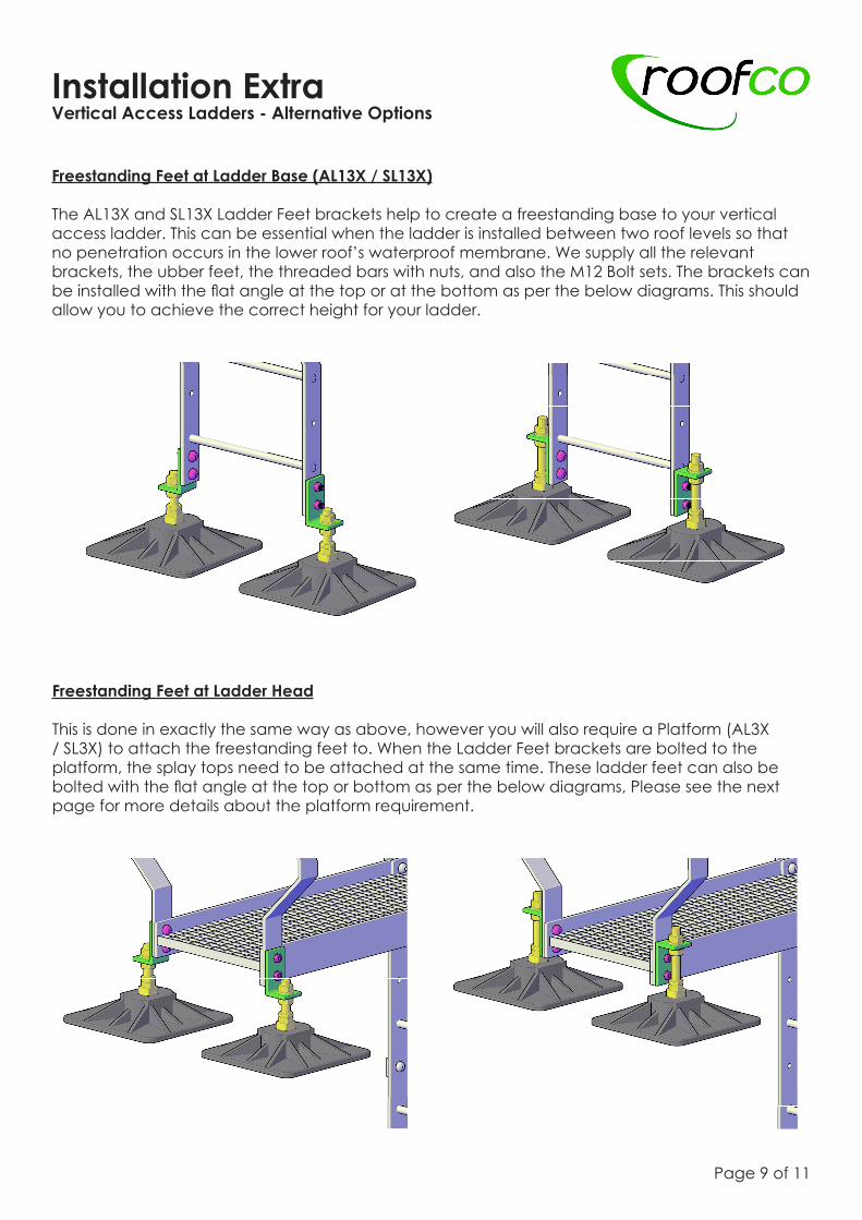
Freestanding Feet at Ladder Base (AL13X / SL13X)
The AL13X and SL13X Ladder Feet brackets help to create a freestanding base to your vertical access ladder. This can be essential when the ladder is installed between two roof levels so that no penetration occurs in the lower roof’s waterproof membrane. We supply all the relevant brackets, the ubber feet, the threaded bars with nuts, and also the M12 Bolt sets. The brackets can be installed with the flat angle at the top or at the bottom as per the below diagrams. This should allow you to achieve the correct height for your ladder.
Freestanding Feet at Ladder Head
This is done in exactly the same way as above, however you will also require a Platform (AL3X / SL3X) to attach the freestanding feet to. When the Ladder Feet brackets are bolted to the platform, the splay tops need to be attached at the same time. These ladder feet can also be bolted with the flat angle at the top or bottom as per the below diagrams, Please see the next page for more details about the platform requirement.
Page 9 of 11
Installation ExtraVertical Access Ladders - Alternative Options
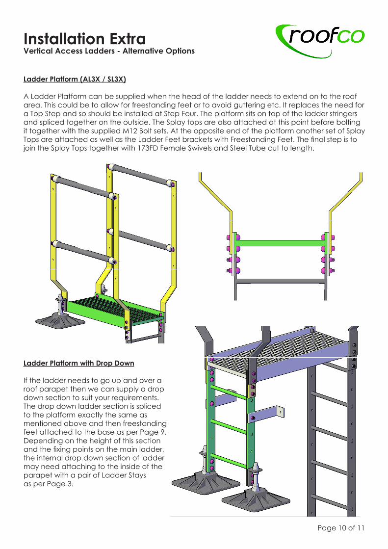
Ladder Platform (AL3X / SL3X)
A Ladder Platform can be supplied when the head of the ladder needs to extend on to the roof area. This could be to allow for freestanding feet or to avoid guttering etc. It replaces the need for a Top Step and so should be installed at Step Four. The platform sits on top of the ladder stringers and spliced together on the outside. The Splay tops are also attached at this point before bolting it together with the supplied M12 Bolt sets. At the opposite end of the platform another set of Splay Tops are attached as well as the Ladder Feet brackets with Freestanding Feet. The final step is to join the Splay Tops together with 173FD Female Swivels and Steel Tube cut to length.
Page 10 of 11
Ladder Platform with Drop Down
If the ladder needs to go up and over a roof parapet then we can supply a drop down section to suit your requirements. The drop down ladder section is spliced to the platform exactly the same as mentioned above and then freestanding feet attached to the base as per Page 9. Depending on the height of this section and the fixing points on the main ladder, the internal drop down section of ladder may need attaching to the inside of the parapet with a pair of Ladder Stays as per Page 3.
Maintenance Vertical Access Ladders - System Maintenance
Page 11 of 11
• We recommend that the ladder installation should be inspected periodically by a competent person. The frequency of these inspections will depend upon the environment, location, and utilisation, but should be at least every twelve months.
• Visual inspection of the complete installation in accordance with the current needs of the client. Check if any new equipment has been installed on the roof that may require further access.
• Check against the original installation drawing to see if any part of the installation has been modified.
• Check that the ladder is straight and level.
• Check all bolts and fixings are in place and sufficiently tightened including those fixing into the wall. This is to ensure there has been no tampering or removal.
• When standard kit components are fully assembled, as our product literature, into a complete access ladder, the ladder will conform to BS 4211:2005+A1:2008.
Re-CertificationVertical Access Ladders - System Re-Certification
Address:Roofco LtdUnit One,Ross Street,Darnall,SheffieldS9 4PU
Telephone:+44 (0) 114 243 6001
Fax:+44 (0) 114 243 6060
Email:[email protected]
• The system is maintenance free, however if cleaning is required, use only a mild detergent and water (such as a domestic washing up liquid) in order not to damage any of the galvanised steel or aluminium coating.
• If the optional self closing gate has been specified and installed, it is recommended this is checked and greased on a regular basis to ensure free action on self closing.
• If the anti climb security plate is specified and installed, the security device used to lock the door, should be inspected at an agreed interval.


![Interior Vertical Surfacing Installation-Corian[1]](https://static.fdocuments.in/doc/165x107/54780c645906b5aa318b46bf/interior-vertical-surfacing-installation-corian1.jpg)