version 3 Nov 2017 EASY-BUILD BR Mk1 CATERING CARS ASSEMBLY INSTRUCTIONS. stock... ·...
17
"EASY-BUILD" BR Mk1 CATERING CARS ASSEMBLY INSTRUCTIONS. THIS KIT CONTAINS SMALL PARTS THAT MAKE IT UNSUITABLE FOR UNSUPERVISED CHILDREN. SAFETY FIRST! IN ORDER TO CONSTRUCT THIS MODEL YOU WILL BE USING VOLATILE SOLVENTS, ALWAYS FOLLOW THE MANUFACTURERS INSTRUCTIONS AND ENSURE ADEQUATE VENTILATION. YOU WILL ALSO REQUIRE THE USE OF SHARP TOOLS - REMEMBER FINGERS ARE USUALLY EASIER TO CUT THAN THE MATERIALS IN THIS KIT! WORK STEADILY AND SAFELY AT ALL TIMES. PLEASE READ THESE INSTRUCTIONS FULLY BEFORE PROCEEDING WITH ASSEMBLY AS MORE THAN ONE ORDER OF CONSTRUCTION MAY BE USED. KIT PACKING CHECKLIST 1) Floor x1 2) Roof x1 3) Sides x2 4) Bogies pack 5) Window Pack (Etched frames + glazing) 6) Corridor Connections x2 7) Castings And Details Pack 8) End And Underframe Mouldings x2 9) ABS Angle Extrusions 10) Wire (3 sizes) 11) Fret Of Etched Components INTRODUCTION The general idea for assembly is to construct a box with a removable roof, which enables interior details to be fitted exactly where they should be relative to window and door openings. In order to get the most from your kit we recommend you read these instructions in full prior to commencing construction making notes as to any assembly options, or changes to the suggested order you think would suit your method of building better. However, we suggest you do adhere to the order of construction as we know it works! We only recommend solvents suitable for ABS plastics such as Carrs Plastic Weld, or EMA Plastic Weld, Two-part epoxy resins are suitable for fixing the larger metal parts (see instructions for suitable alternatives in particular situations). IMPORTANT NOTE: Prior to commencing construction please take a few moments and check the parts for signs of incomplete moulding/casting. Whilst we try to ensure any substandard parts are not packed, some still find their way into the box occasionally. Should any such parts be found contact Easy-Build at our Camelford address, or email [email protected]. Thank you. version 3 Nov 2017
Transcript of version 3 Nov 2017 EASY-BUILD BR Mk1 CATERING CARS ASSEMBLY INSTRUCTIONS. stock... ·...

"EASY-BUILD" BR Mk1 CATERING CARSASSEMBLY INSTRUCTIONS.
THIS KIT CONTAINS SMALL PARTS THAT MAKE IT UNSUITABLE FOR UNSUPERVISEDCHILDREN. SAFETY FIRST! IN ORDER TO CONSTRUCT THIS MODEL YOU WILL BE USINGVOLATILE SOLVENTS, ALWAYS FOLLOW THE MANUFACTURERS INSTRUCTIONS ANDENSURE ADEQUATE VENTILATION. YOU WILL ALSO REQUIRE THE USE OF SHARP TOOLS -REMEMBER FINGERS ARE USUALLY EASIER TO CUT THAN THE MATERIALS IN THIS KIT!WORK STEADILY AND SAFELY AT ALL TIMES. PLEASE READ THESE INSTRUCTIONS FULLYBEFORE PROCEEDING WITH ASSEMBLY AS MORE THAN ONE ORDER OF CONSTRUCTIONMAY BE USED.
KIT PACKING CHECKLIST1) Floor x1 2) Roof x1
3) Sides x2 4) Bogies pack
5) Window Pack (Etched frames + glazing) 6) Corridor Connections x2
7) Castings And Details Pack 8) End And Underframe Mouldings x2
9) ABS Angle Extrusions 10) Wire (3 sizes)
11) Fret Of Etched Components
INTRODUCTIONThe general idea for assembly is to construct a box with a removable roof, which enables interior detailsto be fitted exactly where they should be relative to window and door openings. In order to get the mostfrom your kit we recommend you read these instructions in full prior to commencing construction makingnotes as to any assembly options, or changes to the suggested order you think would suit your methodof building better. However, we suggest you do adhere to the order of construction as we know it works!We only recommend solvents suitable for ABS plastics such as Carrs Plastic Weld, or EMA PlasticWeld, Two-part epoxy resins are suitable for fixing the larger metal parts (see instructions for suitablealternatives in particular situations).
IMPORTANT NOTE:Prior to commencing construction please take a few moments and check the parts for signs ofincomplete moulding/casting. Whilst we try to ensure any substandard parts are not packed, some stillfind their way into the box occasionally. Should any such parts be found contact Easy-Build at ourCamelford address, or email [email protected]. Thank you.
version 3 Nov 2017

So let’s get started by washing all the moulded parts in warm water and washing-up liquid to removeany moulding and machining lubricants...
PREPARING THE SIDES1) The sides should be sanded all over with wet-n-dry (600 grit is ideal) to identify any low spots,continue until the side has a consistent appearance over its entire surface.
2) Check each side moulding against the edge of the end mouldings.You may also opt to mark each end and side to ensure they can beassembled in the same relative order later. Remove about 3mm of the topand bottom moulded ridges that provide physical locating surfaces for floorand roof. This allows the sides to fit snuggly against the end mouldings.
3) Drill through all the pre-marked holes in the sides as follows:
0.7mm - Door hinges. Kitchen doors vertical handrails.
0.7mm - Door bump-stops (these are the holes in the middle of the door panels with acorresponding hole to the left, or right of the door).
0.5mm - passenger door grab handles.
0.5mm - Door handles (T-handles). NOTE: this dimension is for using the new cast brass T-handles, the older turned brass types require a 1.2mm dia. hole
4) Carefully remove raised burr from the door opening score marks with a craft knife, work slowlyand re-open score marks as necessary until desired effect has been achieved.
**TIP - Use a gentle scraping action followed by 800 wet-n-dry (used wet). Alternatively, a smallchisel can be used to shave off the burrs. Old flat needle files can be ground into chisels and areideal for this purpose. Be careful not to dig into the surrounding surface of the sides.
5) Check the ends of the side mouldings for cutting burrs, removing as necessary ensuring the edgeremains square and true. Likewise check all the window openings for burrs - gently scrape the edgesas required. CAUTION - don't be too enthusiastic with the knife! Now thoroughly rub down whole sidewith 800 grit wet-n-dry with plenty of water and rinse with clean water.
6) Moving on to the door hinges, count how many are required for the type of coachbeing constructed. You will need 2 tall and 1 short hinge per door remembering that theshort hinge goes in the centre with a large hinge top and bottom. Remove an equal numberof ‘butterflies’ from the etch, 1 for each hinge. The hinge piece is pushed through a butterflyshaped backing piece then glued into the hole in the side trapping the butterfly with the hinge.
7) Cut the door bump-stops from the spue and glue into the appriopriate holes with superglue.Apply the glue from the inside of the hole and push in the bump-stop from the outside.
8) Carefully cut the window frames from the etch and file the tags smooth taking care not to fileinto the frame itself. Fit the toilet window vent centrally on its backing prior to frame fitment. DO NOTfold out the central ventilator opening tabs of the main windows until the window frames are fitted.
9) Before installing the etched window frames check the fit of the window glazing within theopenings. Carefully file, scrape, or sand the edges of the glazing panels until they fit snuggly, but 2
Inside of side moulding
Top ridge
Bottom rib
Tall Short
Hinges

not sloppy nor tight. Remember that the windows glazing inside the kitchen area were either frosted, orwhite. Frosted windows can be simulated by rubbing the inside face with 800-grit wet-n-dry beforefitting.
Using a slower acting superglue may be preferable when fitting the window frames as it would allowyou more time to align the window frame before the glue sets.
10) Check that the frames fit the openings (dry run) - the openings should be very slightly largerthan the locating lip on the reverse of the window frame.
11) Apply a small amount of superglue directly to the rear frame at the top only. Position the top ofthe frame into the opening and allow to set. Now, using a small piece of flat material roughly the widthof the window frame, gently press the bottom into place and apply glue to the frame/window openingjoint from the inside (this is most easily achieved with an old craft knife blade dipped in superglue).Once the frame is secure apply more glue to the side joints as appropriate.
12) Remove any excess glue after glue has set using a glass fibre pen, or fine abrasive paper (glassfibre pen found to be best).
13) Once all is set and clean of excess glue, fold the central ventilator tabs outward. First bend thetab slightly outwards before using small pliers both in a squashing action, but don’t close the tabs tighttogether leave a small gap between. You may prefer to leave this until the sides have been assembled,but before painting.
That completes the sides for now.
ROOF PREP - DO NOT MISS ANY OF THESE STEPS
You will notice your roof has a curve due to the moulding process this is useful when fitted as itensures the roof is a tight fit in the centre of your coach.
14) Remove and cutting burrs from the roof ends and about 7mm of theinside edge of the roof mounting groove at both ends of the roof - this allowsthe roof to sit snugly over the end mouldings. NOTE: DO NOT remove any ofthe (visible) outer edge of the groove as this represents the roof gutter.
15) Take an end and check the fit of the underside of the roof to the top of theend. The two parts should sit snuggly together, if not check the areasshown in the diagram (right) and carefully trim away just sufficientmaterial to allow the parts to meet. The roof moulding sits over the topof the end moulding with an over hang of about 1mm at the gutter
16) Put a strip of masking tape down the centre of your roof ontowhich you can mark the positions of roof fittings from the sketchesprovided (see end of instructions).
16.1) Drill the marked vent positions approx. 2.0mm dia. to accept the roof vents. Also make aphysical mark where any fans are to be placed and a smaller hole (approx. 1.2mm) for the water fillers(if fitted) then remove tape.
NOTE, the roof fittings positions are scaled from various photographs and so absolute accuracycannot be guaranteed. If you have more accurate information to hand please tell us and we
3
REMOVE A SMALLAMOUNT
(LOOKING AT END)
ENSURE A GOOD FITAT THIS POINT
ROOF MOULDINGMODIFIED AS SUPPLIED

will update our instructions.
17) Give the whole roof a good rubbing down with wet-n-dry to smooth out any surfaceimperfections from the manufacturing process. Dont’ forget the inside if you intend to paint the interior.
18) Cut the roof vents from the spues leaving no more than a 2mm spigot with which to attach thevent to the roof. Leaving the spigot longer than 2mm might interfere with the roof fixing clamps later.
19) Fit the roof details - superglue is ideal for this. Before fitting the water filler castings you mightconsider leaving them removable, i.e. create the water pipes and simply wedge them into the holesonce the roof is in position. This option allows the roof to be removed without the pipes becomingvulnerable as part of a detached roof.
FLOOR PREP20) Check the floor moulding for flatness - if it appears too distorted (some curvature is quite normal)bend it in the reverse direction to correct. Place the floor moulding top side down on a flat surface tobegin detailing.
**TIP - Fixing the floor down on to a piece of melamine, or glass with double-sided tape works verywell.
21) Remove the U-shaped and ‘T’ section mouldings from the sprue, cleaning off any flash asnecessary. The ‘U’ shaped moulding are in fact slightly too tall and should be shortened by approx.2.5mm at this stage.
22) Using the locating ‘dots’ on the floor surface, affix 5 of the ‘U’ mouldings to the floor betweenthe raised centre beams in the order of 1 short, 3 tall, 1 short. Allow joints to fully harden beforecontinuing.
23) Cut 2 lengths of angle truss moulding 209mm and make a notch in one side of the angle 53mmfrom each end (see diagram below) - a simple cut with a junior hacksaw will create a sufficiently widenotch for our needs. Check allmeasurements against your underframebefore cutting.
24) Gently bend the ends of the trusses(closing the notches) to pre-form to shape.Attach the formed trusses to the outsideedges of the centre ‘U’ shaped mouldings with the notchesaligned with the centres of the outer tall ‘U’ mouldings and theends aligned with the edges of the shorts ‘U’ mouldings. Allowthe solvent to harden on the centre ‘U’ mouldings beforeattaching the ends to the short ‘U’ mouldings as these may need bending a little more to achieve goodalignment of the parts. The top of the angle should be level with the tops of the ‘U’ shaped mouldings.
25) With the angle trussing firmly in place affix the T-section mouldings as shown in the diagram(right overleaf) between the truss angle and inner face of the solebar. There are long and short T-section mouldings supplied, the short ones are fitted against the short U-shaped mouldings (closest tothe bogies), the longer ones being fitted to the centre U-shaped mouldings.
26) Locate the two aluminium bogie mounting turnings and prepare them by scoring their
53mm53mm
209mm
4
Angle truss moulding
U-mouldings (short & long)

upper surface (the upper surface has a spigotthat locates in the hole in the floor). Treat themounting areas likewise. Using a strongadhesive affix the two bogie mountings in theirrespective holes.
**TIP - Bogies present quite a load to theirmountings mainly due to the ease by which they getknocked and twisted when the model is off the tracks, it istherefore necessary to select an adhesive capable ofwithstanding such shocks. Two part epoxy resins are moresuitable than superglues.
27) To make a much stronger job of fixing the bogie pivotsin place, you might consider a ‘belt and braces’ approach by adding a mechanical fixing to themounting. Good results have been achieved by drilling two 1mm holes through the bogie mountings andfloor (once the mounting has been fixed in place) either side of the bogie pivot bolt, tap 12BA. Nowsecure the bogie pivot in place by bolting down through the coach floor with short 12 BA bolts.
28) Clean up all the metal under-floor castings as required. Fold up and assemble the etched brassdynamo mounting brackets and attach dynamo casting. Drill the dynamo mounting lugs 0.7mm andhang the dynamo on the etched mounting arms with brass rod (see photos on CD).Mount the bracketto the floor so that the bracket is hard up against the angled trussing, this ensure the dynamo pully isin the right location - it is NOT on thecentreline!
NOTE: If you intend to fit the lower steps(where fitted) for the Kitchen access doorssome undreframe details may needmounting away from the solebars so thatthe steps don’t foul platform edges, etc.The steps hang 15mm below theunderside of the floor. Check photographsfor locations.
29) (Not required for Dia. 23/24 cars) Remove the Regulator Carrier Frame from the etch and foldalong the half etches to form a U-shaped bracket. Fold in the fuse box mounting plate (away from halfetch) and mount the cast metal regulator box and fuse box as shown right (see photos on our CD).
30) Remove the brake V hangers from the etch and bend thebottom edge along the half etched line to form a right angle. Checkthe etched holes in the brake levers for size and open outaccordingly. Check and adjust the central holes in the brake pull-rodadjusters also to 1mm dia. - do this before removing the parts fromthe etch as they’re much easier to handle.
31) Drill a 1mm dia. hole in the centre of the brake cylinders andglue in a short piece of brass rod (about 20mm protruding out of the cylinder is sufficient). To
FLOOR
BOGIE MOUNTING
12BA BOLTS
5
REGULATOR BOX - FUSE BOX
TOP
DYNAMO MOUNTINGARMS
1mm WIRE
ASSEMBLEDDYNAMO ANDBRACKET
U-mouldings (short & long)
Angle truss moulding T-section mouldings

ensure the brake cylinder sits level once in position file back the mounting lug on one side only - thecentral ribs of the floor are taller than the outer (solebar) ribs. Check against the floor until the cylinderwill sit squarely. Fit the brake cylinders in place using the underfloor diagram as a plan.
**TIP - Two part epoxy resins are more suitable than superglues since they are less brittle. Goodresults have been obtained using impact adhesives such as Evostick (the new Evostick Serious Gluehas recently been recommended although we have not tried it ourselves). Whatever type of adhesiveyou choose remember to roughen-up the surfaces first to improve adhesive grip.
32) Cut two brake lever pivot bars 39mm long from 1.6mm brass rod and thread the levers andspacers as shown right. The first brake cylinder lever (longer lever)should be about 8mm from the end of the rod and the brake pull rodlever (the shorter lever) about 11mm from the other end, which shouldbe the floor centreline (adjust as required). (see photos on our CD).The two sets of levers should be form a right angle relative to eachother as shown far right.
33) Attach to the central brake lever a pull-rod andadjuster that would actually pull the bogie brake gear (seeright). The pull-rod length should be trimmed to length justforward of the inner axle of the adjacent bogie.
34) Fit the remaining castings in place according theunderfloor plan. The brake DA valves mount on thesloping parts of the truss bars. Afix the brass mountingonto the rear of the casting and then onto the truss bars.The etched mounting is angled to ensure the DA valve is vertical once fitted. Position the valves about10mm from the brake pivot bar (towards the end of the floor). If required, a short length of soft copperwire can be fixed to the top of the valve and into the bottom face of the brake cylinders (see photoson our CD).
ENDS PREP 35) It is assumed you already know what periodand livery you intend for your coach, if not now is thetime to make that decision. The reason for needingto make that decision now is because some detailsare not required for later periods of the BR MK1stock. As a rough guide the end steps are not(always) required from the later maroon periodonwards, i.e. into the blue/grey livery. However,there are examples of end steps still to be found oncertain stock, so checking an example of yourparticular prototype is strongly recommended. In theabsence of specific information, it is recommendednot to fit the end steps on stock intended to bepainted in the blue/grey livery. Another complicationis the fact that there are examples where visual
BRAKE LEVERS
2x LEVER SPACERS
6
End StepLocations
Remove these moulded details on one end only
Make pipework from1mm brass rod
Operating rodsmade from 0.5mm
wire
Add notches, or drillsmall holes for pipes
‘Shelf’ made from
styrene strip if fitted
Handrails fitted to some vehicles – check yourprototype

evidence of the positions of the steps remains when the steps themselves have been removed. Youcan simplify the preparation of the ends by simply leaving the small rectangular pads in place on theend mouldings. Alternatively, flush ends can be modelled by carefully paring off the moulded pads andsanding the areas smooth. Also some catering cars had short vertical handrails on the ends. Attend tothese points now...
36) On one end only remove the moulded details at the top of the ends that represent the emergencybrake equipment. Again paring off the thickest parts first followed by gentle filing and sanding smooth.
37) At the opposite end drill through the outer ‘ears’ of the emergency brake equipment (0.5mmdia.) and also through the moulded ‘block’ horizontally. Next drill two 1mm dia. holes - one in thebottom of the aforementioned ‘block’ and a second in the bufferbeam just to the left of the centralsection of the end (see diagram). Also, if you wish to add electrical cables to the round connectionboxes moulded on the end (both ends in fact) drill an appropriately sized hole for the wire being used.Soft copper wire (5amp fuse wire not supplied) is ideal to depict this detail and add the End CableElectrical Plugs etching having first folded it in half which will produce a slot for the wire to fit inside.(see photos on our CD).
38) Having drilled all the necessary holes make and fit the details from wire as appropriate. FInally,if the end will be fitted with pipes for the water tanks, either drill a small hole in the moulded brackets,or cut a small notch in the inner edge of the brackets to clip the pipe into. If the end doesn’t have anypipe work, these brackets can be removed and the area filed smooth.
39) Moving to the bufferbeam fit the end step to the left of the left hand buffer detail and fit the bufferheads into the stocks. Add the Bufferbeam Coupling Reinforcing Plates to the coupling opening andopen the slot to acommondate the coupling hook (laminated from two etched parts).
Before fitting the ends to the floor moulding check your chosen prototype to determine which end tofit the emergency brake equipment. One would assume it should be fitted at the same end of eachcoach, but that appears not to be the case. When checking photographs the brake equipment detailscan be found both adjacent to, or at the opposite end to the dynamo on the same type of vehicle (?).
40) With the ends fully prepared they can now be fitted to the floor moulding. Give the inside faceof the bufferbeam a quick rub over with a file and present it to the end of the floor moulding. Lookingat the (soon to be) inside of the end moulding you will notice a step at the top of the bufferbeam - thisis aligned with the top of the floor moulding. Hold the end in place and apply solvent to the joint - bepatient the end will have a tendency to simply fall off initially. Once the end has been ‘weakly’ held inplace by the solvent, check the end is stood vertically (from every direction) and is located centrally overthe end of the floor. So, Check: 1) the inner ‘step’ is level with the top of the floor; 2) the end doesn’tlean in to, or out of the coach interior; 3) the end is centrally located on the end; 4) the end is stoodvertical when viewed end on. That all sounds very complicated, but in fact is quite easy to achieve witha little patience. If the end becomes too stuck to adjust simply apply more solvent to soften the joint.Set the floor aside now for the end joints to fully harden.
**TIP - Once you are satisfied with the positioning of the ends, it is a good idea to reinforce theunderside of the floor/end joint using 1mm (40thou) styrene micro-rod.
41) Now is a good time to fit the steps to the solebars. Temporarily place a side between the endsand mark the positions of the steps relevant to the doors. The steps themselves are cut from 7
5mm x 1mm styrene strip. Single doors steps are 20mm long. On some vehicles there are pairs ofdoors used for stocking the kitchen, these should have a step made approximately 4mm wider than thecombined width of the doors. Attach the steps to the side of the solebar level with the bottom edge.Brass reinforcing pieces are supplied on the door hinges etch (bend 90o and affix with superglue to theinside of the solebar and bottom of the step).
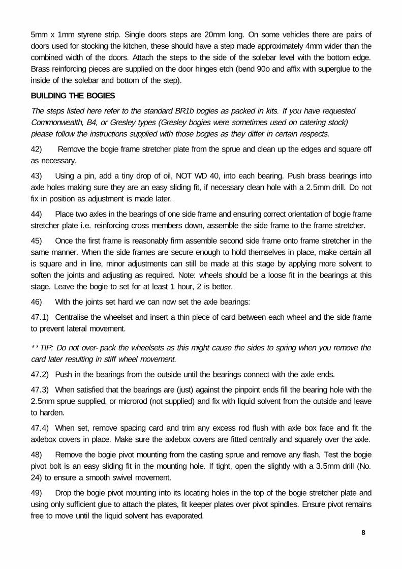
BUILDING THE BOGIES
The steps listed here refer to the standard BR1b bogies as packed in kits. If you have requestedCommonwealth, B4, or Gresley types (Gresley bogies were sometimes used on catering stock)please follow the instructions supplied with those bogies as they differ in certain respects.
42) Remove the bogie frame stretcher plate from the sprue and clean up the edges and square offas necessary.
43) Using a pin, add a tiny drop of oil, NOT WD 40, into each bearing. Push brass bearings intoaxle holes making sure they are an easy sliding fit, if necessary clean hole with a 2.5mm drill. Do notfix in position as adjustment is made later.
44) Place two axles in the bearings of one side frame and ensuring correct orientation of bogie framestretcher plate i.e. reinforcing cross members down, assemble the side frame to the frame stretcher.
45) Once the first frame is reasonably firm assemble second side frame onto frame stretcher in thesame manner. When the side frames are secure enough to hold themselves in place, make certain allis square and in line, minor adjustments can still be made at this stage by applying more solvent tosoften the joints and adjusting as required. Note: wheels should be a loose fit in the bearings at thisstage. Leave the bogie to set for at least 1 hour, 2 is better.
46) With the joints set hard we can now set the axle bearings:
47.1) Centralise the wheelset and insert a thin piece of card between each wheel and the side frameto prevent lateral movement.
**TIP: Do not over-pack the wheelsets as this might cause the sides to spring when you remove thecard later resulting in stiff wheel movement.
47.2) Push in the bearings from the outside until the bearings connect with the axle ends.
47.3) When satisfied that the bearings are (just) against the pinpoint ends fill the bearing hole with the2.5mm sprue supplied, or microrod (not supplied) and fix with liquid solvent from the outside and leaveto harden.
47.4) When set, remove spacing card and trim any excess rod flush with axle box face and fit theaxlebox covers in place. Make sure the axlebox covers are fitted centrally and squarely over the axle.
48) Remove the bogie pivot mounting from the casting sprue and remove any flash. Test the bogiepivot bolt is an easy sliding fit in the mounting hole. If tight, open the slightly with a 3.5mm drill (No.24) to ensure a smooth swivel movement.
49) Drop the bogie pivot mounting into its locating holes in the top of the bogie stretcher plate andusing only sufficient glue to attach the plates, fit keeper plates over pivot spindles. Ensure pivot remainsfree to move until the liquid solvent has evaporated.
8

9
**TIP: Some people prefer to use a larger piece of sheet styrene (not supplied) rather than themoulded keeper plates supplied.
50) If desired, fit the brake shoes on the inside of the sideframe. They should be positioned just offthe wheels with the circle detail on the shoe just visible below the bottom of the side frame. Mountingpairs of brakeshoes on short lengths of wire makes the fitting much easier, use superglue to affix thewire to the underside of the bogie frame.
If you have followed us so far you will now have a detailed roof, carriage sides, the floor with endsattached and completed bogies. At this point you have the choice of completing the constuction byassembling the sides to the floor/end assembly, or to paint the floor/end assembly and sides separatelybefore assembling. Both methods have advantages and disadvantages. I now favour completingconstruction before any painting is started, but masking can be a pain! Before any painting is attemptedgive everything a thorough wash with water containing a mild detergent and allow to dry thoroughly.Space does not permit a detailed description of how to paint your carriage so it is assumed that youalready have that knowledge and skill, or know someone who does. If you are having difficulty in thisarea please contact us for advice. Remember also to paint the inside of the carriage sides and roof tobrighten the interior once assembled. However, if you have opted to keep the sides separate until thepainting is done do not paint below the moulded side ridge and scrape excess paint from the end facesof the sides as solvent will be applied here during final assembly.
BODY ASSEMBLY CONTINUED...If you didn’t assemble the sides before painting you should now have to hand the finished carriagesides, floor, roof and bogies - let’s build the body. But first a word of caution: REMEMBER YOU AREHANDLING FINISHED COMPONENTS. KEEP SHARP OBJECTS WELL AWAY FROM THE WORKAREA WHEN THEY ARE NOT ACTUALLY BEING USED.
51) First of all check that you have the floor and sides correctly orientated - this is most easily doneby aligning the door steps mounted on the solebars with the doors they serve.
Gently roughen the upper surface to the edges of the floor where the side moulding will sit.
**TIP- Ensure you remove traces of paint from the surfaces to be fixed together as the paint willseriously affect the solvent’s ability to create a secure joint.
52) Working with the side furthest away from you, i.e. you are looking from the inside of the coach,fit the side between the two ends. It is often necessary to bow the side in order to get it in place. Nowstarting at one end press the side against the floor and also against the moulded end rib and applysolvent between the end and the side. Follow this by applying solvent along the side/floor jointprogressively along the length of the whole side and eventually the end rib at the other end. Worksteadily and hold the parts together until the bond is sufficiently strong to hold the parts in place. Turnthe coach around and repeat for the other side.
**TIP- Be generous with the solvent along the floor/side joint, less so at this stage at the ends assolvent here can seep more easily onto the painted exterior surfaces.
53) Insert all glazing and secure in place with Canopy Glue (RC Modelers glue for instance). Thisadhesive dries clear and quickly and is also flexible. Dilute a small amount to the consistancy of milkand add a single drop of detergent. Apply with a small paintbrush to the inside joint between the glazing

panels and window opening. This is best achieved by laying the coach on its side. Door glazing can befitted in a similar manner, but with the glue applied to the edge of the window surround.
54) If you intend to detail the interior it would be a good idea to paint the interior floor area now.
55) Before fitting the roof turn the coach over and fit the couplings.
56) Fit the two roof retaining 'nuts' in the roof channel and slide to a position directly above that ofthe 4mm hole in the floor at each end (approximately 19mm from the ends of the roof). You will needto give the ‘nut’ a few strokes with a flat file to make sliding it into the slot easier, however don’t makeit too sloppy as it can then become very difficult to locate it with the bolt.
57) Position the roof in place and secure with the long bolts provided. You may find the sides havebowed inward since you assembled them. If this is the case work initially with one side and locate thetop of the side into the groove in the underside of the roof. Once one side is in place gentle pushingand squeezing will be sufficient to encourage the other side into place. Don’t apply too much tensionwith the fixing bolts until the sides are located into the roof grooves as this can impede fitting.
58) (If fitted to the coach type being built) Fit the roof in position and form from wire the water fillerpipes at the ends of the coach. With care a small hole can be drilled into the roof water filler castingand the wires soldered, or glued inside. Since each coach type had different patterns of pipe-work alongthe roof, follow photographs of your chosen prototype if possible.
59) Fit the door furniture (handles and grab handles, etc.) as appropriate for the types of doors fittedto your vehicle.
60) Fit the bogies in place with the short bolts provided. Adding a smear of glue on the thread ofthe bolt prior to fitting will be sufficient to prevent the bolt from unscrewing during use - don’t apply toomuch or you may not be able to get the bogies off again - not good!
61) Finally, fit the corridor connections in place (see appendix for assembly instructions) ensuringthey are fitted vertical and centrally on the end - the bottom of the corridor connection should be levelwith the top of the bufferbeam ‘step’.
We hope you have enjoyed building this kit and welcome your comments.
SHAWN KAY MARCH 2017CONTACT INFORMATION
“EASY-BUILD” Trenarth, Victoria Road, Camelford, Cornwall, PL32 9XE.
Tel: 07834 063966 (before 9pm please)
e-mail: [email protected] web: www.easybuildcoaches.co.uk
DIMENSIONAL DATABuffer centre height from rail head 3ft 51/2in 24.2mm
Body height (bottom) from rail head: 4ft 1in 28.58mm
Overall body height to apex of roof (not vents, pipes, or periscopes) 12ft 41/2in 86.6mm
10

NOTES:
11

12
ETCHED DETAILS SHEET
Regulator Box Mounting
Bufferbeam Steps
Bufferbeam CouplingReinforcing Plates
Coupling Hooks
Corridor ConnectionLamp Irons
Brake Cylinder Levers
Door Step Reinforcing
DA Valve Mounting
End Steps Door Grab Handles Door Hinges And‘Butterflies’
Guard’s Door handlesBaggage Door Handles
Brake Pullrod adjuster
Brake pullrod lever
End Cable ElectricalPlugs
Brake V Hangers
Dynamo Mountings
Suburban Lamp Irons
Suburban Lamp SwitchLever
Under Body Steps - BGsEtc.
Brake Cylinder LeverSpacers
Roof /End PipesMounting Eyes

13
C1C2
C3
C4C4
C5C5
C5C5
C6C7
C8C9
C10
C11
C1C2
AR
RA
NG
EM
EN
TO
F C
OM
PO
NE
NT
S F
OR
AD
IAG
RA
M23/2
4 C
OA
CH
UN
DE
RF
RA
ME
. OT
HE
R D
IAG
RA
MS
FO
LLO
WT
HE
SA
ME
AR
RA
NG
EM
EN
TF
OR
BR
AK
E A
ND
DY
NA
MO
DE
TA
ILS
WIT
H O
TH
ER
DE
TA
ILS
PO
SIT
ION
ED
AC
CO
RD
ING
LY. (N
OT
TO
SC
ALE
)
Water
filler pipe-w
ork takes
the approxim
atestyles show
n here. If the filler is adjacent to theend of the coach the pipes are form
ed as shown
right. Those
positioned further
away
from
thecarriage end are form
ed as shown left. N
ote -these are only to give you a feel for the style -please refer to photographs before m
aking theparts. The shape of the pipes as they run dow
nthe end of the body roughly follow
the edge of thebody end step positions - they w
ere also used ashandrails.
Pipe length determined by
position of filler in roof
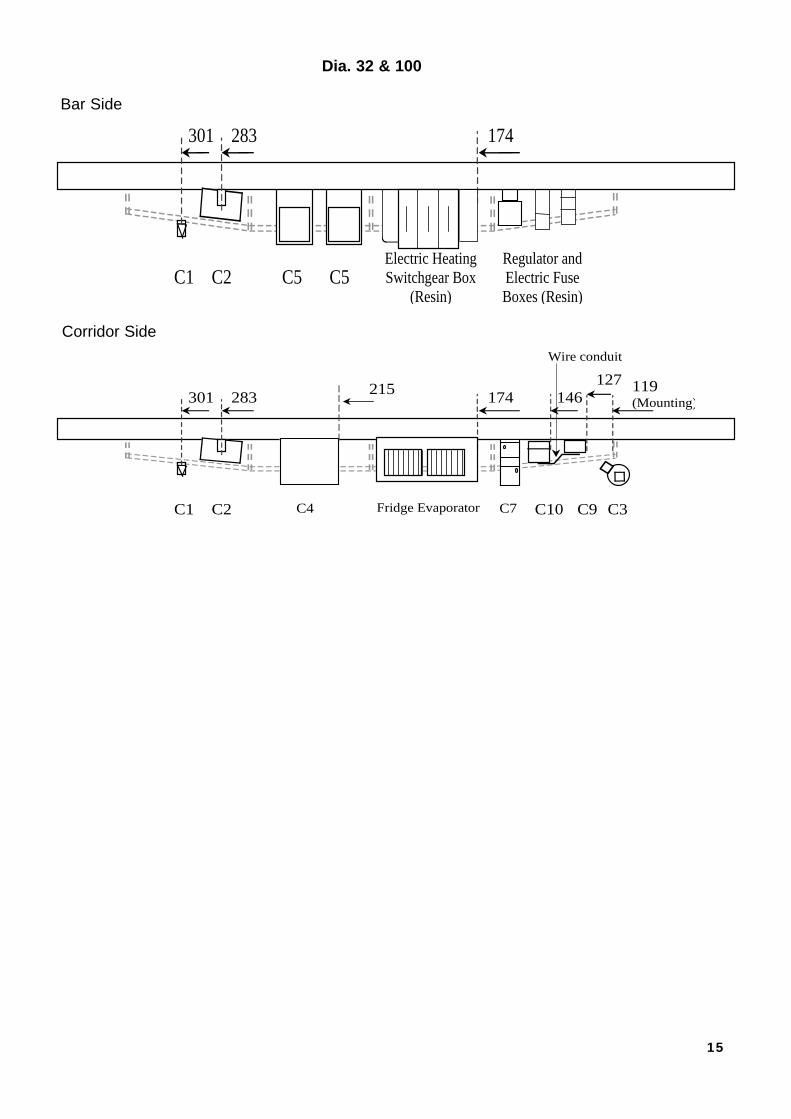
Key To Castings (not all castings listedare in every kit, see appropriate diagramfor those included).C1: DA ValveC2: Vacuum CylinderC3: DynamoC4: Battery BoxC5: Gas Bottle BoxC6: Compressor Box (with Louvres)C7: Tall Switch BoxC8: Electrical Box (same as C6 but withoutlouvres).C9: Fuse BoxC10: Small Electrical BoxC11: Regulator (3-Stepped resin casting)

14
C1 C5C2 C5 C5 C5 C9C10C8 C3
305
301 283 197247 174224 119 (Mounting)
Wire conduit
146 127
NOT FITTED TOGRIDDLE CAR
C1 C2 C4 C4 C7 C6C11
142 159 173 185 238 280 300
Underframe Layouts Shown As Viewed On Track (NOT TO SCALE)Measurements shown from opposite ends so that all marking can be done from one end
Kitchen Side
Corridor Side
C1 C2
142 159
C5 C5C4C12
194 232 270 292
C1 C2 C3
305301 283
C4C6
172235 119 (Mounting)
Buffet Side
Corridor Side
Dia. 97/8/9 - RMB
Dia.23/24 - RU & Dia 30 - Griddle
15
C4C1 C2 C9C10 C3
215301 283 174119(Mounting)
Wire conduit
146127
C7Fridge Evaporator
C5 C5C1 C2
301 283 174
Electric HeatingSwitchgear Box
(Resin)
Regulator andElectric FuseBoxes (Resin)
Bar Side
Corridor Side
Dia. 32 & 100

16
DIA 23/24 DIA 30
C/L C A B W / F
14 303 215 278 262
48 320 (Rect. Vent) 245
82 343 267
130 359
171 375
211
245
277
303
423
DIA 97/98/99 DIA 32
A B Sq Vents A B W / F
24 24 (A side) 274 231 24
111 111 (A side) 318 Fan Fan 442
166 166 (B side) 338 199 183
303 361 Rnd Fan 217
361 408 (B side) 316
408
274 316
318 338
DIA 100
A
150 + 6mm offset
165
217
235 + 6mm offset
248 W / F
(A side)193.5
TANK FILLERS 3.5mm
TOWARDS
B SIDE OF ROOF
B VENTS
A VENTS
C/L
ALL M
EASUREM
ENTS FRO
M THIS EN
D
CORRIDO
R THIS SIDE
6.5mm
6.5mm
ROOF VENT MEASUREMENTS (in mm)

17
The basic components are illustratedhere (right). Note that the bellows havea front and rear, with the square sectionbeing the rear. The mounting plateshould be painted to match the colour ofthe end of the carriage, this is best donebefore assembly.
1) Remove the mounting and striker plates from the sprue andsmooth off the feeds.
2) Inspect the edges of the bellows for signs of flash, which gives theedge a crinkley appearance. To remove the flash, carefully clip the thincrinkles back to the smooth egde, this is best done with scissors, or endclippers. Finish off the trimming with 400 grit abrasive paper as required.Also, give the the ends a rub over to improve adhesion.
3) The floor across the bottom of the bellows can be removed toincrease flexiblility when used within a train, or left in place for an endcoach.
3.1) To remove the floor section, cut vertically downwards onthe inside of the bellows opening with a sharp blade. DO NOTreduce the bellows height.
4) Starting at with bottom corner of the striker plate, secure thebellows with a spot of superglue. The bottom of the bellows align withthe top of the opening in the striker plate.
5) Keeping the edge of the bellows aligned with the edge of thestriker plate, continue gluing up the side to the point where the archbegins. STOP.
6) Repeat steps 4 and 5 on the other side.
7) The bellows around the arched opening can now be fixedensuring they follow the outline of the curve.
8) Now repeat steps 4 to 7 to afix themounting plate noting the bottom of the
mounting is level with the bottom of the bellows. Ensure the door outlinefaces into the bellows before you start gluing!
9) Give the edges a gentle rubbing over with fine abrasive paper toremove any excess glue.
Square channeltowards mounting
Bellows bottomview Mounting Bellows
Striker plate
Alignmounting withbottom ofbellows
Keep bellowsaligned withedge ofmounting
Keep bellowsaligned withedge ofmounting
Start fixing fromthe bottomcorner
APPENDIX
Corridor Connection Assembly.