Version 2 Release 4 z/OS - IBM€¦ · Migrating to z/OS Version 1 Release 4

z/OSVersion 2 Release 3
JES3 Initialization and Tuning Guide
IBM
SA32-1003-30

Note
Before using this information and the product it supports, read the information in “Notices” on page297.
This edition applies to Version 2 Release 3 of z/OS (5650-ZOS) and to all subsequent releases and modifications untilotherwise indicated in new editions.
Last updated: 2019-02-16© Copyright International Business Machines Corporation 1988, 2017.US Government Users Restricted Rights – Use, duplication or disclosure restricted by GSA ADP Schedule Contract withIBM Corp.

Contents
List of Figures....................................................................................................... ixList of Tables........................................................................................................ xi
About This Document..........................................................................................xiiiWho Should Use This Document............................................................................................................... xiiiHow to Use This Document....................................................................................................................... xiiiWhere to find more information................................................................................................................ xiii
How to send your comments to IBM......................................................................xvIf you have a technical problem.................................................................................................................xv
Summary of changes...........................................................................................xviSummary of changes for z/OS Version 2 Release 3 (V2R3)..................................................................... xviSummary of changes for z/OS Version 2 Release 2 (V2R2)..................................................................... xviz/OS Version 2 Release 1 summary of changes.......................................................................................xvii
Chapter 1. Introduction......................................................................................... 1Developing Your Installation Plan............................................................................................................... 1Preparing for JES3....................................................................................................................................... 1
Installing JES3........................................................................................................................................2Running the Hardware Configuration Definition Program..................................................................... 2Initializing MVS....................................................................................................................................... 2
Chapter 2. Initializing JES3................................................................................... 3Modifying the JES3 cataloged start procedure........................................................................................... 3Modifying or Creating a JES3 Initialization Stream.....................................................................................7Organizing the initialization stream............................................................................................................. 8
Using a segmented initialization stream................................................................................................8Testing Your Initialization Stream............................................................................................................. 10
How to Run Step 1................................................................................................................................10How to Run Step 2................................................................................................................................11Storage Requirements for the Initialization Stream Checker............................................................. 12Abnormal Termination of the Initialization Stream Checker...............................................................12
Starting JES3..............................................................................................................................................12Hot Start............................................................................................................................................... 13Hot Start with Analysis.........................................................................................................................13Hot Start with Refresh..........................................................................................................................14Hot Start with Refresh and Analysis.................................................................................................... 15Warm Start............................................................................................................................................16Warm Start with Analysis..................................................................................................................... 16Warm Start to Replace a Spool Data Set............................................................................................. 16Warm Start with Analysis to Replace a Spool Data Set.......................................................................17Cold start.............................................................................................................................................. 17Local start............................................................................................................................................. 18
Tuning JES3................................................................................................................................................19JES3 Monitoring................................................................................................................................... 19Using JMF to Measure JES3 Performance...........................................................................................19
Using JES3 Auxiliary Address Space (JES3AUX)...................................................................................... 20Maintaining JES3....................................................................................................................................... 20
JES3 Maintenance philosophy.............................................................................................................20Running JES2 and JES3 on the same image is not supported ...........................................................24
Dynamically changing the JES3 configuration..........................................................................................24
iii

Chapter 3. Providing security for JES3..................................................................29Planning for Security..................................................................................................................................29Using RACF to provide security................................................................................................................. 30How JES and RACF Work Together............................................................................................................32Defining JES3 and the JES3AUX Address Space in the RACF Procedures Table.....................................33Forcing Batch Users to Identify Themselves to RACF.............................................................................. 33Defining and Grouping Operators..............................................................................................................33
Understanding How to Provide Access to Resources......................................................................... 34Understanding Security Labels............................................................................................................ 35
Security Labels for JES Resources............................................................................................................ 35JES3 Installation Exits that Affect RACF-Provided Security...............................................................36Giving JES3 Access to Resources........................................................................................................ 37
JES User ID Early Verification....................................................................................................................37TSO/E logon................................................................................................................................................37User ID Propagation When Jobs Are Submitted.......................................................................................37
Control of User ID Propagation............................................................................................................ 38Where NJE jobs are verified.......................................................................................................................38How SYSOUT requests are verified........................................................................................................... 39Controlling Access to Data Sets JES Uses.................................................................................................39Controlling Input to Your System.............................................................................................................. 40
How RACF Validates Users...................................................................................................................40Controlling the use of job names and job classes............................................................................... 41Authorizing the Use of Input Sources..................................................................................................45
Authorizing Network Jobs and SYSOUT (NJE).......................................................................................... 46Authorizing Inbound Work................................................................................................................... 46Authorizing Outbound Work.................................................................................................................60
Authorizing TCP/IP/NJE Secure Signon.................................................................................................... 63Examples.............................................................................................................................................. 63
Controlling Access to Data That Resides on Spool................................................................................... 64Protecting SYSIN and SYSOUT.............................................................................................................64Protecting JESNEWS............................................................................................................................ 67How RACF Affects Jobs Dumped from and Restored to Spool (JES3 Only).......................................67
Authorizing Console Access...................................................................................................................... 68MCS Consoles....................................................................................................................................... 68Remote Workstations (RJP/RJE Consoles)..........................................................................................68
Controlling Where Output Can Be Processed........................................................................................... 70Authorizing the Use of Your Installation's Printers...................................................................................71Using RACF to Authorize the Use of Operator Commands....................................................................... 72
Profile (Entity) Names for JES3 Commands........................................................................................ 73Who Authorizes Commands When RACF Is Active............................................................................. 76
Using JES3 to Provide Security..................................................................................................................77JES3 Initialization Statements that Affect Security............................................................................ 77JES3 Installation Exits that Affect JES3-Provided Security............................................................... 80Using JES3 to Control Access to RJP Workstations............................................................................ 81Using JES3 to Authorize the Use of Operator Commands.................................................................. 81
Chapter 4. JES3 job management.........................................................................87Input Service..............................................................................................................................................87
Reader Phase........................................................................................................................................87Control statement processing phase...................................................................................................87
Converter/Interpreter Service................................................................................................................... 90Converter/Interpreter Phase............................................................................................................... 91Prescan Phase...................................................................................................................................... 91Postscan Phase.................................................................................................................................... 92
JES3 Resource Allocation..........................................................................................................................92MVS Allocation Compared with JES3 MDS Allocation........................................................................ 93
iv

Types of Setup...................................................................................................................................... 96Initializing MDS.....................................................................................................................................98Operator Control of MDS....................................................................................................................100
Job Selection and Scheduling................................................................................................................. 100Comparison of JES3 and WLM initiator management.......................................................................101Classifying Jobs..................................................................................................................................104Pre-execution delays......................................................................................................................... 105Defining service classes and performance goals.............................................................................. 108Job Selection Algorithm for JES3-Managed Initiators......................................................................109Job Selection Algorithm for WLM-Managed Initiators......................................................................110Deadline Scheduling.......................................................................................................................... 111Dependent Job Control...................................................................................................................... 112Controlling Job Selection...................................................................................................................114Controlling Job Scheduling................................................................................................................ 118
Output Service......................................................................................................................................... 123Queueing Output................................................................................................................................ 123Scheduling Output............................................................................................................................. 135Writing Output.................................................................................................................................... 136External Writers/SAPI Applications...................................................................................................137NJERDR.............................................................................................................................................. 138Internal Reader.................................................................................................................................. 138Accessing Job Output Through TSO.................................................................................................. 138Output Service Installation Exits....................................................................................................... 139
Purge........................................................................................................................................................ 140
Chapter 5. Defining and managing C/I service.................................................... 141Setting Up C/I Service............................................................................................................................. 141
Advantages to Using C/I FSS Address Spaces.................................................................................. 142C/I FSS address space requirements................................................................................................ 142Defining a C/I FSS address space......................................................................................................143Defining the Maximum Number of CI and POSTSCAN DSPs............................................................ 144
Controlling Jobs Through C/I Service..................................................................................................... 146Controlling Job Flow with Installation Exits......................................................................................147Assigning jobs to the appropriate processor and address space for C/I service............................. 148Using system symbols in source JCL for demand select jobs.......................................................... 149Defining a converter/interpreter options list.....................................................................................150
Managing the Scheduler Work Area........................................................................................................ 150Creating SWA Space...........................................................................................................................151Preventing a Job from Dominating the SWA..................................................................................... 151Preventing Abnormal Termination of JES3 or a C/I FSS Address Space..........................................152
Monitoring and Modifying C/I Service.....................................................................................................154Determining the Status of C/I Service............................................................................................... 154Modifying C/I Service......................................................................................................................... 155
Managing Procedure Libraries.................................................................................................................156Updating Procedure Libraries............................................................................................................ 156Displaying the Status of Procedure Library Data Sets...................................................................... 157
Chapter 6. Defining and Managing Spool Data Sets............................................. 159Defining Spool Data Sets......................................................................................................................... 159
Determining How Many Spool Data Sets You Should Allocate......................................................... 159Allocating Spool Data Sets.................................................................................................................160Formatting Spool Data Sets............................................................................................................... 160
Using Spool Partitions............................................................................................................................. 162Advantages to Spool Partitioning...................................................................................................... 162Isolating Different Spool Data Types.................................................................................................163Defining Spool Partitions....................................................................................................................163Defining spool partition overflow.......................................................................................................164
v

Specifying Spool Data Sets as Members of Spool Partitions............................................................ 165Specifying a Spool Partition for Spool Data.......................................................................................165Determining the order of spool partition overrides...........................................................................166How the User Can Request a Spool Partition.................................................................................... 167
Defining Spool Space Allocation Units.................................................................................................... 170Defining a Track Group.......................................................................................................................170Determining Track Group Allocation Sizes........................................................................................ 172
Managing Spool Space.............................................................................................................................173Adding or deleting a spool data set................................................................................................... 173Replacing a spool data set................................................................................................................. 175Moving a spool data set to another DASD volume............................................................................ 176Balancing the workload across spool partitions............................................................................... 176Deleting Output Data Sets................................................................................................................. 177Freeing Spool Space Using the Dump Job Facility............................................................................ 177How to Use Performance Measurement Tools to Tune JES3 Spool................................................. 177
Chapter 7. Defining Consoles and Message Routing.............................................181Defining Consoles.................................................................................................................................... 181
Defining MCS Consoles...................................................................................................................... 181Defining RJP Consoles....................................................................................................................... 182
JES3 Console Management.....................................................................................................................182Operator Communication.................................................................................................................. 182Input Processing................................................................................................................................ 182
MCS Console Management......................................................................................................................182Entering commands.................................................................................................................................183Defining the hardcopy log........................................................................................................................183
Recording message traffic................................................................................................................. 185Rules...................................................................................................................................................186
Defining message routing........................................................................................................................186Where and How Messages Originate................................................................................................. 187Where messages can go.................................................................................................................... 188Understanding the General Path of a Message................................................................................. 188JES3 Destination Classes and MVS Routing Codes...........................................................................191Two Types of Messages..................................................................................................................... 192Routing JES3 Messages to Consoles.................................................................................................193Using MSGROUTE to Control Message Routing.................................................................................193Message Routing Exceptions............................................................................................................. 194Diagnosing Misrouted Message Traffic..............................................................................................196Suppressing the Display of Messages............................................................................................... 196Automating message processing.......................................................................................................199
Chapter 8. Defining and Managing JES3 Resources............................................. 201JES3 Data Sets.........................................................................................................................................201
Allocating JES3 Data Sets..................................................................................................................201Allocating the JES3 Checkpoint Data Sets........................................................................................ 202Defining the Maximum Number of Jobs for Your Complex...............................................................203JCT Utility (IATUTJCT)....................................................................................................................... 210Identifying Resident Data Sets.......................................................................................................... 214Using system catalogs....................................................................................................................... 214
I/O Devices...............................................................................................................................................214Defining I/O Devices to JES3............................................................................................................. 215Defining Process Modes.....................................................................................................................216Running a Printer Under an Output Writer Functional Subsystem................................................... 217Using the Infoprint Server for z/OS Printer Inventory.......................................................................221Defining a device configuration..........................................................................................................221Maintaining a Device Configuration Using HCD.................................................................................222Allocating an I/O Device to JES3....................................................................................................... 225
vi

Grouping I/O devices......................................................................................................................... 226Specifying Device Fencing................................................................................................................. 227Dynamically Reconfiguring I/O Devices.............................................................................................227Volumes..............................................................................................................................................228How Resource Definition Affects JES3 Resource Management....................................................... 228
Chapter 9. Defining and managing JES3 mains and storage.................................237Defining mains......................................................................................................................................... 237
General considerations...................................................................................................................... 237Defining a JES3 XCF group...................................................................................................................... 238Running JES3 in a sysplex environment................................................................................................. 240Defining Storage...................................................................................................................................... 241
Defining Buffers..................................................................................................................................242Using the Writer Output Multitasking Facility....................................................................................245
Chapter 10. JES3 Remote Job Processing...........................................................247Binary Synchronous Communication Remote Job Processing.............................................................. 247
Data Security Considerations............................................................................................................ 247Data Compression..............................................................................................................................247Operator Communications.................................................................................................................247Debugging Facilities........................................................................................................................... 248Initialization Statements that Affect BSC RJP.................................................................................. 248
Systems Network Architecture Remote Job Processing........................................................................249SNA RJP implementation of SNA concepts.......................................................................................249Function Management Presentation Services (FMPS)...................................................................... 251JES3 to VTAM Interface..................................................................................................................... 253Initialization Statements that Affect SNA RJP.................................................................................. 255Maximum Record Lengths for SNA RJP Devices............................................................................... 256Basic Exchange Support.................................................................................................................... 256Exchange Support.............................................................................................................................. 256Exchange and Basic Exchange Initialization Considerations............................................................256
Chapter 11. JES3 Networking............................................................................ 259Networking Protocols.............................................................................................................................. 259
Differences between Networking Protocols......................................................................................259Converting Networking Protocols...................................................................................................... 260
Types of nodes.........................................................................................................................................262Converting A Node To TCP/IP............................................................................................................ 263
Defining the Home Node......................................................................................................................... 263Defining a Remote Node..........................................................................................................................264
Specifying a communications path for indirectly-connected nodes................................................ 265Defining an Alias...................................................................................................................................... 265Defining a Spool Partition........................................................................................................................ 266Defining TCP/IP/NJE................................................................................................................................266BSC Considerations................................................................................................................................. 267
Defining the buffer size...................................................................................................................... 267Specifying passwords........................................................................................................................ 268Defining BSC Communication Lines.................................................................................................. 269Logical senders: How JES3 names them.......................................................................................... 271
DESTDEF Statement................................................................................................................................ 273SNA Considerations................................................................................................................................. 273
Changing Node Definitions.................................................................................................................273How Restarts Affect Networking Jobs...............................................................................................273
TCP/IP Considerations.............................................................................................................................274Changing Node Definitions.................................................................................................................274How Restarts Affect Networking Jobs...............................................................................................274TCP/IP prerequisites.......................................................................................................................... 274
vii
Rerouting Jobs and SYSOUT................................................................................................................... 275Networking Job Numbers........................................................................................................................275Defining a Network Message Destination............................................................................................... 275Monitoring the job entry network with installation exits........................................................................275Monitoring Files Sent through TSO/E TRANSMIT or CMS SENDFILE.....................................................279
Deleting Files from the Spool.............................................................................................................279General NJE Considerations....................................................................................................................279
Chapter 12. JES3 support for IBM tape libraries................................................. 281JES3 support overview............................................................................................................................281
Allocation for tape library data sets.................................................................................................. 281JES3 initialization statements........................................................................................................... 281Library configuration example........................................................................................................... 284
Operational considerations..................................................................................................................... 287Unchanged functions......................................................................................................................... 287Modified functions..............................................................................................................................287JES3 limitations................................................................................................................................. 288
Mount failures.......................................................................................................................................... 290JES3......................................................................................................................................................... 290
Tape verification processing (IATLVVR module)............................................................................... 291Migration considerations................................................................................................................... 292IBM 3590/3592 support for JES3..................................................................................................... 292
Appendix A. Accessibility...................................................................................293Accessibility features.............................................................................................................................. 293Consult assistive technologies................................................................................................................ 293Keyboard navigation of the user interface.............................................................................................. 293Dotted decimal syntax diagrams.............................................................................................................293
Notices..............................................................................................................297Terms and conditions for product documentation................................................................................. 298IBM Online Privacy Statement................................................................................................................ 299Policy for unsupported hardware............................................................................................................299Minimum supported hardware................................................................................................................300Trademarks.............................................................................................................................................. 300
Index................................................................................................................ 301
viii

List of Figures
1. Sample JES3 Cataloged Start Procedure......................................................................................................42. Structure of the JES3 initialization stream................................................................................................... 83. Example of JES3 initialization stream with INCLUDE statements...............................................................94. Editing to add an FSS managed printer...................................................................................................... 265. Editing to add a SNA/RJP work station and its devices............................................................................. 266. The ADDFSS member..................................................................................................................................277. *MODIFY,CONFIG log for member ADDFSS - duplicate FSS names......................................................... 278. *MODIFY,CONFIG with IATUX15 exit processing...................................................................................... 289. Sample Section of a CLIST that Defines RACF Profiles.............................................................................. 3210. Where NJE Jobs are Verified.................................................................................................................... 3811. How SYSOUT Requests are Verified......................................................................................................... 3912. Which NODES Profiles Are Used?............................................................................................................. 5013. Example: simple NJE user translation..................................................................................................... 5614. Example: Simple NJE User Translation Using &SUSER........................................................................... 5715. Example: trusted, semitrusted, and untrusted nodes............................................................................. 5816. Overview of Job Flow to Input Service.....................................................................................................8817. Overview of Pre-Execution Job Delays.................................................................................................. 10718. Response Time/Velocity Goals...............................................................................................................10819. JES3 Job Selection Environment........................................................................................................... 11620. Sample Job Using IEBDG to Format a Spool Data Set...........................................................................16121. Hardcopy log migration scenario............................................................................................................18422. Sample Log Entries (with 2-digit-year dates)........................................................................................ 18523. Sample Log Entries (with 4-digit-year dates)........................................................................................ 18624. Simplified path of a message issued from a local processor................................................................ 18925. Simplified path of a message issued from a global processor.............................................................. 19026. Examples of message suppression........................................................................................................ 19827. Sample JCL for IATUTJCT Utility............................................................................................................ 21128. IATUTJCT Utility Start Command........................................................................................................... 21329. IATUTJCT Utility Migrating Start Command...........................................................................................21330. IATUTJCT Utility Fallback Start Command.............................................................................................21331. Use of FSSNAME= Parameter.................................................................................................................22132. Range of devices..................................................................................................................................... 22133. Subgeneric Groups..................................................................................................................................22634. DEVICE Statement — Example............................................................................................................... 22835. JES3-managed, MVS-managed, and jointly managed device determination.......................................22936. Defining a JES3 XCF group - putting the pieces together......................................................................23937. Example JES3 sysplex environment...................................................................................................... 24138. Algorithm for minimum buffer size.........................................................................................................24239. JSAM buffer pool algorithm....................................................................................................................243
ix
40. Overview of SNA Environment for JES3.................................................................................................25041. JES3-VTAM Interface..............................................................................................................................25142. How JES3 Creates a Logical Sender Name............................................................................................ 27243. Job related installation exits.................................................................................................................. 27744. SYSOUT Related Installation Exits......................................................................................................... 27845. Command Related Installation Exits......................................................................................................27846. Libraries defined for the configuration example....................................................................................28547. MVS UNITNAMEs defined for the configuration example..................................................................... 28548. SETNAME statements for the configuration example........................................................................... 28649. HWSNAME Statements for the Configuration Example.........................................................................28650. DEVICE Statements for the Configuration Example.............................................................................. 28751. Sample JES3 definitions for IBM 3590 Model B1x with an IBM tape library....................................... 291
x

List of Tables
1. Description of the Statements in the JES3 Cataloged Start Procedure.......................................................42. Data Sets Required to Run the Initialization Stream Checker................................................................... 113. Modifiable JES3 Initialization Statements for Hot Start with Refresh.......................................................144. Hot Start With Refresh - Effect on FSSs......................................................................................................155. Characteristics of Global Processor Starts................................................................................................. 186. Benefits of Protecting JES3 Resources...................................................................................................... 297. RACF Classes Used to Protect JES3 Resources......................................................................................... 308. Assigning Security Labels for the XYZ Corporation.................................................................................... 359. Installation Exits that Affect JES3 Security When RACF Is Active............................................................ 3610. NODES class keywords and the UACC meaning for inbound jobs........................................................... 5111. NODES class keywords, UACC and SYSOUT ownership when node is not defined to &RACLNDE ........5412. RACF Functions Required to Protect JES3 Resources.............................................................................7213. RACF Profile Names for JES3 Commands................................................................................................7314. RACF Profile Names for //*PROCESS Commands.................................................................................... 7615. Command Authority Checking When RACF OPERCMDS Class Is Active.................................................7616. JES3 Initialization Statements that Provide Security Protection............................................................ 7817. Installation Exits that Affect JES3-Provided Security............................................................................. 8118. Authority Levels for Remote Consoles..................................................................................................... 8219. JES3 Commands Allowed from MCS Consoles........................................................................................ 8420. Where a job will execute based on //*MAIN JECL, JOB JCL and CLASS statements..............................8921. Overview - Job Selection........................................................................................................................ 10322. Types of Job Delays................................................................................................................................ 10623. FREE=CLOSE and SPIN=UNALLOC Effect on SYSOUT Created by Automatic Restart Management...12224. JES3 DEFINED DEFAULTS - Overriden by OUTSERV Initialization Statement......................................12425. Output parameter overrides using a direct OUTPUT JCL statement for WTR and HOLD queue..........12526. Example of FORMS Override Using Direct //*FORMAT Statements for WTR Queue.............................12727. Example of Output Parameter Overrides Using Direct //*FORMAT Statements for HOLD Q................12828. Example of Output Parameter Overrides Using Default OUTPUT Statements for WTR and HOLD
Queue....................................................................................................................................................... 12929. Example of FORMS Overrides Using Default //*FORMAT Statements for WTR Q................................. 13030. Example of Output Parameter Overrides Using Default //*FORMAT Statements for HOLD Queue......13131. Example of FORMS Overrides Using Default OUTPUT and //*FORMAT Statements for WTR Queue... 13232. Example of Output Parameter Overrides Using Direct and Default //*FORMAT Statements for
HOLD Q..................................................................................................................................................... 13333. Output Service Installation Exits............................................................................................................13934. Installation Exits for Monitoring JCL Interpretation.............................................................................. 14735. Procedure for Selecting and setting an address space JCL statement limit.........................................15236. Spool partition overrides........................................................................................................................ 16637. Spool partitions used in spool partition example PART 1..................................................................... 168
xi

38. Spool partitions used in spool partition example PART 2..................................................................... 16939. Record, Track, and Cylinder Characteristics for DASD Devices.............................................................17140. Summary of Spool Tuning Techniques................................................................................................... 17841. Valid Destination Classes and Their Corresponding Routing Codes..................................................... 19142. Physical blocks per track and cylinder...................................................................................................20743. Default Value(s) for ALTPM= When MODE=COMP................................................................................. 21744. Default Values for ALTPM= When MODE=FSS....................................................................................... 21745. Deleting a Device Configuration Using HCD........................................................................................... 22446. Who Controls Data Set Access............................................................................................................... 23047. JES3 Volume Management.....................................................................................................................23348. JES3 and System Handling of Allocation Requests............................................................................... 23349. SCS Function Characters Supported by FM Inbound Routines............................................................. 25150. SCS Function Characters Supported by FM Outbound Routines...........................................................25251. Parameter requirements for the NJERMT statement............................................................................ 26252. The number of logical senders created and suffixes used for valid combinations of the MAXLINE
and STREAM parameters......................................................................................................................... 27253. Network installation exit summary........................................................................................................ 27654. Device-specific library unitname table.................................................................................................. 282
xii

About This Document
This document supports z/OS® (5650-ZOS). This document is intended for any JES3 complex that runsz/OS MVS.
This document provides guidance information about initializing, tuning, and managing JES3.
Who Should Use This DocumentJES3 system programmers or anyone who is responsible for initializing, tuning, or managing JES3 shoulduse this document. This document also contains information that is useful when planning for JES3.
How to Use This DocumentTo use this document you need not read it from cover to cover. Depending on your knowledge of JES3 andyour information needs, you can read selected topics. The first time you come to this document, however,you should read the table of contents, the figure list, and the "Introduction" to help you understand thetype of information presented and the organization of the information.
Where to find more informationThe following table lists document that contain information related to the information provided in thisdocument.
When this document references information in other documents, the shortened version of the documenttitle is used. The following table shows the complete titles and order numbers of the document that arenot listed in z/OS Information Roadmap.
Title Order Number
HLASM Language Reference SC26-4940
HLASM Programmer's Guide SC26-4941
z/OS DFSMS Managing Catalogs SC23-6853
z/OS DFSMSdfp Checkpoint/Restart SC23-6862
z/OS Communications Server: SNA Network Implementation Guide SC27-3672
z/OS SDSF Operation and Customization SA23-2274
z/OS Security Server RACF General User's Guide SA23-2298
z/OS Security Server RACF Security Administrator's Guide SA23-2289
z/OS SDSF Operation and Customization SA23-2274
3390 Direct Access Storage Introduction GC26-4574
Using 3390 DASD in an MVS Environment GC26-4573
Reference Summary for the 3390 SX26-1676
© Copyright IBM Corp. 1988, 2017 xiii

xiv z/OS: JES3 Initialization and Tuning Guide

How to send your comments to IBM
We invite you to submit comments about the z/OS product documentation. Your valuable feedback helpsto ensure accurate and high-quality information.
Important: If your comment regards a technical question or problem, see instead “If you have a technicalproblem” on page xv.
Submit your feedback by using the appropriate method for your type of comment or question:Feedback on z/OS function
If your comment or question is about z/OS itself, submit a request through the IBM RFE Community(www.ibm.com/developerworks/rfe/).
Feedback on IBM® Knowledge Center functionIf your comment or question is about the IBM Knowledge Center functionality, for example searchcapabilities or how to arrange the browser view, send a detailed email to IBM Knowledge CenterSupport at [email protected].
Feedback on the z/OS product documentation and contentIf your comment is about the information that is provided in the z/OS product documentation library,send a detailed email to [email protected]. We welcome any feedback that you have, includingcomments on the clarity, accuracy, or completeness of the information.
To help us better process your submission, include the following information:
• Your name, company/university/institution name, and email address• The following deliverable title and order number: z/OS JES3 Initialization and Tuning Guide,
SA32-1003-30• The section title of the specific information to which your comment relates• The text of your comment.
When you send comments to IBM, you grant IBM a nonexclusive right to use or distribute the commentsin any way appropriate without incurring any obligation to you.
IBM or any other organizations use the personal information that you supply to contact you only about theissues that you submit.
If you have a technical problemIf you have a technical problem or question, do not use the feedback methods that are provided forsending documentation comments. Instead, take one or more of the following actions:
• Go to the IBM Support Portal (support.ibm.com).• Contact your IBM service representative.• Call IBM technical support.
© Copyright IBM Corp. 1988, 2017 xv

Summary of changes
This information includes terminology, maintenance, and editorial changes. Technical changes oradditions to the text and illustrations for the current edition are indicated by a vertical line to the left ofthe change.
Summary of changes for z/OS Version 2 Release 3 (V2R3)The following changes are made for z/OS Version 2 Release 3 (V2R3).
New
• With APAR OA49166, “Authorizing jobs” on page 51, Table 16 on page 78, 'JES3 InitializationStatements that Provide Security Protection', and Table 51 on page 262, 'Parameter requirements forthe NJERMT statement', are updated.
Changed
• “OSE Processing” on page 133 is modified to include a new rule.• With APAR OA49796, modifications are made to “Dynamically changing the JES3 configuration” on
page 24.• With APAR OA47444, modifications are made to “Adding or deleting a spool data set” on page 173.• With APAR OA48349, NJERMT initialization statement parameters PWD= and EXPWD= can be used
when TYPE=TCPIP is specified. See “Types of nodes” on page 262 for an update to Table 51 on page262, 'Parameter requirements for the NJERMT statement'.
Summary of changes for z/OS Version 2 Release 2 (V2R2)The following changes are made for z/OS Version 2 Release 2 (V2R2).
New
• No new information.
Changed
• Modified Modifying the JES3 cataloged start procedure and the description of the statements in theJES3 cataloged start procedure table. For details, see the topic about “Modifying the JES3 catalogedstart procedure” on page 3.
• Modified JES3AUX. For details, see the topic about “Using JES3 Auxiliary Address Space (JES3AUX)” onpage 20.
• Modified Dynamically changing the JES3 configuration section of Initializing JES3. For details, see thetopic about “Dynamically changing the JES3 configuration” on page 24.
• Modified Accessing Job Output Through TSO of JES3 Job Management. For details, see the topic about“Accessing Job Output Through TSO” on page 138.
• Modified Managing procedure libraries of defining and managing C/I service. For details, see the topicabout “Managing Procedure Libraries” on page 156.
• Modified Displaying the status of procedure library data sets of defining and managing C/I service. Fordetails, see the topic about “Displaying the Status of Procedure Library Data Sets” on page 157.
• Modified “Running JES3 in a sysplex environment” on page 240.• Modified TCP/IP prerequisites. For details, see the topic about “TCP/IP prerequisites” on page 274.
xvi z/OS: JES3 Initialization and Tuning Guide

Deleted
• Removed an exception of substituting DISP=SHR for DISP=OLD from Allocating the JES3 checkpointdata sets. For details, see the topic about “Allocating the JES3 Checkpoint Data Sets” on page 202.
• Removed Falling Back from Release HJS7730 (or above) to Release HJS7720 (or below) section from“TCP/IP Considerations” on page 274 of Chapter 11, “JES3 Networking,” on page 259.
z/OS Version 2 Release 1 summary of changesSee the Version 2 Release 1 (V2R1) versions of the following publications for all enhancements related toz/OS V2R1:
• z/OS Migration• z/OS Planning for Installation• z/OS Summary of Message and Interface Changes• z/OS Introduction and Release Guide
Summary of changes xvii

xviii z/OS: JES3 Initialization and Tuning Guide

Chapter 1. Introduction
You must make many decisions and perform many tasks to install, initialize, and start JES3. Thisdocument is intended to guide you through the decision making process and help you perform therequired tasks. Before installing JES3 however, you must make sure that your installation has thehardware needed to support JES3. You should also plan the layout of your I/O devices and learn how toinstall JES3.
Before you read this document, you should read z/OS JES3 Introduction to gain a basic understanding ofJES3. For information on software and hardware requirements, and compatibility and coexistencerequirements, see z/OS Information Roadmap
Developing Your Installation PlanYou should develop a well-thought-out plan to perform a smooth and orderly installation of JES3. Yourplan should address questions such as:
• What hardware should I use and how should I configure it?• Must I run the hardware configuration definition (HCD) program?• Must I change any members of SYS1.PARMLIB?• How do I install JES3?
Only after you have developed this plan should you proceed to install JES3.
You must carefully plan the configuration of hardware and software required to satisfy your installation'sneeds. You should also consider ways to reconfigure your complex early in your planning. You can initiallydefine MVS™ processor complexes in ways that will allow reconfiguration without having to restart JES3.For more information about reconfiguring a processor complex, see “Defining Mains” in Chapter 9,“Defining and managing JES3 mains and storage,” on page 237. For information about planning an I/Oconfiguration that supports reconfiguring and for instructions on the reconfiguration process, see z/OSProblem Management.
JES3 provides great flexibility in the location of equipment in your machine room. For example, you canuse additional operator consoles to physically separate the operational functions (card I/O, printing, tapesetup) across multiple systems and locate them in areas most convenient to your local work flow. You canlocate your card readers, punches, and printers in the job dispatching area where programs are submittedfor execution and output is returned. You can place your mountable I/O units in an area that is convenientto the tape and disk library. In addition, you can place an operator console at the tape and disk librarian'sdesk to receive library volume fetch requests. You can then place the processing units in some other areathat is free of the congestion typical of the peripheral units.
Preparing for JES3Before you can initialize JES3, you must first install the MVS base control program (BCP) and JES3, andthen initialize MVS. The following steps precede JES3 initialization:
1. Install the MVS BCP2. Install JES33. Run the MVS hardware configuration definition (HCD) program.4. Update the MVS SYS1.PARMLIB data set5. Initialize MVS
For more detailed information, see z/OS Planning for Installation.
© Copyright IBM Corp. 1988, 2017 1

Installing JES3Use the System Modification Program/Extended (SMP/E) to install JES3. SMP/E provides two methods forinstalling JES3, the GENERATE command and the RECEIVE, APPLY, and ACCEPT (RECEIVE/APPLY/ACCEPT) command set. For more information about using either of these methods, see SMP/E for z/OSUser's Guide.
Running the Hardware Configuration Definition ProgramThe hardware configuration definition (HCD) program provides the way for you to define I/Oconfigurations to MVS. You can also use HCD to request I/O configuration data for the JES3 initializationstream checker.
HCD enables you to maintain multiple I/O configurations. For more information about HCD, see z/OS HCDUser's Guide.
Initializing MVSAn operator can specify certain system parameters during MVS initialization or you can specify systemparameters in an MVS data set named SYS1.PARMLIB. The purpose of SYS1.PARMLIB is to provide manyinitialization parameters in a predefined form in a single data set, and thus minimize the need for operatorentry of parameters during MVS initialization.
To use JES3 as the primary job entry subsystem, you must specify JES3 in member IEFSSNxx ofSYS1.PARMLIB. Otherwise, MVS will default to IEFSSN00, which specifies JES2. You must also define allconsoles in your installation in the CONSOLxx member of SYS1.PARMLIB to ensure console integrity. Seez/OS MVS Initialization and Tuning Guide for information about how to use SYS1.PARMLIB.
2 z/OS: JES3 Initialization and Tuning Guide

Chapter 2. Initializing JES3
Each time JES3 starts, initialization occurs. During initialization, MVS runs the JES3 cataloged procedure.The JES3 cataloged procedure is JCL that causes MVS to allocate the data sets required by JES3.Depending on the type of start specified, JES3 will process the JES3 initialization stream, thus initializingitself.
You can tailor JES3 by:
• Modifying the JES3 cataloged start procedure• Modifying the JES3 initialization stream• Using a segmented initialization stream• Creating and using an alternate initialization stream• Coding a program for installation exit IATUX15. An installation exit is a part of JES3 specifically
designed for installations that want to augment or change JES3 processing. For a description of this andother exits, see z/OS JES3 Customization.
• Dynamically reconfiguring JES3
Modifying the JES3 cataloged start procedureThe JES3 cataloged start procedure contains the job control language (JCL) statements needed toallocate the data sets required by JES3. IBM provides a basic cataloged start procedure that is shippedwith JES3. During the construction of the Base Control Program, MVS stores this procedure in a memberof the SYS1.PROCLIB data set. MVS names the member JES3 unless the installation specifies a differentname during system installation.
You can change this procedure by using a text editor or by using the IEBUPDTE utility program. Before youcan make changes, however, JES3 must complete initialization. Changes do not take effect until yourestart JES3. Figure 1 on page 4 shows a sample of the JES3 procedure. This sample contains all of therequired JCL statements. Table 1 on page 4 explains the purpose of each DD statement in theprocedure.
© Copyright IBM Corp. 1988, 2017 3

If you want JES3 functions to be available after JES3 initialization without requiring the *S,JSS command, include the PARM=NOREQ parameter as shown below. //IEFPROC EXEC PGM=IATINTK,DPRTY=(15,15),PARM=NOREQ //STEPLIB DD DISP=SHR,DSN=SYS1.SIATLIB //CHKPNT DD DISP=SHR,DSN=SYS1.JES3CKPT //CHKPNT2 DD DISP=SHR,DSN=SYS1.JS3CKPT2 //JES3JCT DD DISP=SHR,DSN=dsn //spool1 DD DISP=SHR,DSN=dsn . . . //spoolnn DD DISP=SHR,DSN=dsn //JES3OUT DD UNIT=00E //JES3SNAP DD UNIT=AFF=JES3OUT //JESABEND DD UNIT=AFF=JES3OUT //SYSABEND DD UNIT=AFF=JES3OUT //IATPLBST DD DISP=SHR,DSN=SYS1.PROCLIB . . . //IATPLBnn //JES3IN DD DISP=SHR,DSN=SYS1.SIATSAMP(JES3IN00)
If the disk reader facility (DR) is required, specify:
//JES3DRDS DD DISP=SHR,DSN=dsn
Figure 1: Sample JES3 Cataloged Start Procedure
If you introduce an error while changing the procedure, JES3 cannot be restarted. In this case, you mustuse another system (for example, the starter system) to change the procedure.
To help you better understand the cataloged start procedure, Table 1 on page 4 describes the purposeand content of each JCL statement shown in the previous example.
Table 1: Description of the Statements in the JES3 Cataloged Start Procedure.
Statement Notes Description
Notes:
DMay be dynamically allocated.
OOptional; include only if the indicated function is to be used.
RRequired statement.
SMust be on a device that is shared by the global and all local mains.
//IEFPROC R Specifies the name of the JES3 job step task, load module IATINTK.
PARM=NOREQ specifies that JES3 global starts JES automatically. To nullify theparameter you can specify S JES3,PARM= on the start command.
//STEPLIB O Defines the JES3 module library. If used, this library must contain at least thefollowing modules: IATINTK, IATINGL, IATINSV, IATGRSQ, IATGRTX, IATSSDQ,IATSSVT, and IATUX15. This library must not contain any JES3 modules that arein LPA.
4 z/OS: JES3 Initialization and Tuning Guide

Table 1: Description of the Statements in the JES3 Cataloged Start Procedure. (continued)
Statement Notes Description
//CHKPNT | //CHKPNT2 R,S Defines the JES3 checkpoint data set(s). At least one of the two checkpoint datasets must be allocated and cataloged before JES3 operation. Each checkpointdata set must be allocated as a single extent which begins and ends on acylinder boundary. The size of each data set should be at least 2 cylinders on a3330, 3340, 3350, 3375, 3380 or 3390 spool volume. See Chapter 8, “Definingand Managing JES3 Resources,” on page 201 for further allocation information.
//JES3JCT R,D,S Defines the JES3 job control table (JCT) data set. This data set must be allocatedand cataloged before JES3 operation. The data set must be large enough toaccommodate the maximum number of JCT records to be allocated concurrentlyduring normal system operation.
//spool1
. . . //spoolnn
R,D,S Defines the spool data sets. The installation selects the ddnames and data setnames for these statements. The ddname for this statement must be the sameddname specified on the BADTRACK, FORMAT, or TRACK initializationstatements. Spool data sets must be allocated and cataloged before JES3operation. (These data sets may be any size; however, a minimum of 100cylinders is suggested.)
The use of unique data set names for each spool data set allows you tomanipulate those data sets if they are not in use by JES3. Otherwise, if youspecify DSI on the PPT statement of the SCHEDxx member of SYS1.PARMLIB,you won't be able to manipulate the data sets even if they are not in use. This isbecause MVS sets up an ENQ on the data set name to prevent the data set frombeing manipulated while JES3 is running.
When the data set is not in use, then the ENQ can be circumvented using theprocedure described in Renaming a Data Set That Might be in Use in Chapter 2.Managing the Volume Table of Contents of z/OS DFSMSdfp Advanced Services.
//JES3OUT R,D Defines the data set upon which the JES3 initialization stream and initializationerror messages are printed. This data set is de-allocated after initializationcompletes. You can tailor the block size (BLKSIZE) and logical record length(LRECL) values to improve performance. The values you can specify are device-dependent.
//JES3SNAP O,D Defines the data set used if JES3 produces a dump during a hot start, hot startwith analysis, hot start with refresh, hot start with refresh and analysis, warmstart, or warm start with analysis. This data set contains important diagnosticinformation. The information is not available if you define JES3SNAP as adummy data set.
//JESABEND O,D Defines the data set used for a JES3 formatted dump. If omitted, a formatteddump of JES3 control information is not produced.
//SYSABEND or //SYSUDUMP O,D Defines the data set for JES3 system dumps.
//IATPLBST . . . R,D,S Defines the installation's standard procedure library.
//IATPLBnn | //PROCnn O,D,S Defines the installation's standard procedure library or libraries.
Note: If a data set is dynamically allocated as both a JES3 DISKRDR data setand a JES3 PROCLIB data set, the UPDATE= parameter on the JES3 //*MAINstatement (JES3 procedure library update facility) cannot be used to move thedata set.
Initializing JES3 5

Table 1: Description of the Statements in the JES3 Cataloged Start Procedure. (continued)
Statement Notes Description
//JES3IN R Defines the data set containing the JES3 initialization stream. This data set mustbe a blocked or unblocked partitioned data set. The default initialization streamis read from SYS1.SIATSAMP(member JES3IN00).
//JES3DRDS O,D Defines the partitioned data sets containing input for the JES3 disk readerfacility. The maximum block size for this data set is 3200. Concatenated datasets may be used.
The following considerations and restrictions apply to JCL statements in the JES3 cataloged startprocedure.
• Do not code a REGION parameter in the JCL EXEC statement of the start procedure. Doing so wouldaffect performance.
• Do not code FREE=CLOSE on any DD statement.• Do not code a ddname of JS3Dnnnn (nnnn is a 4-digit number) on a DD statement. These ddnamesdefine data sets dynamically allocated by the DYNALLOC initialization statement when there is morethan one DYNALLOC statement with the same DDN parameter value.
• Do not code a ddname of J3INCLnn (nn is 2-digit number) on a DD statement. These ddnames definedata sets dynamically allocated as a result of the INCLUDE statement.
• If the JESABEND or SYSABEND DD statements specify a printer that is also defined on a DEVICEstatement, interleaved output at the printer can occur as a result of the ABDUMP task and the JES3 taskwriting concurrently
• Do not use the ddname END on a spool DD statement.• DD statements added to the JES3 cataloged start procedure:
– Must refer to data sets that are cataloged in the master catalog or that are specified by volume serialnumber.
– Must not specify the * or DATA parameters.• The data set specified on the JES3IN DD statement must be cataloged if:
– Your initialization stream contains INCLUDE statements.– You want to use the *MODIFY,CONFIG command.
• Do not use the same data set name for JES3OUT, JES3SNAP, or JESABEND DD statements if a pre-allocated data set is being used, the results might be unpredictable.
• JES3 uses the DSI PPT specification from the SCHEDxx member of SYS1.PARMLIB. IBM recommendsthat you use DSI so there is an ENQUEUE outstanding on all its data sets (major name=SYSDSN, minorname=dsname) while JES3 is up and running.
Use the following PPT statements to add the DSI specification to SCHEDxx and maintain the otherattributes of the IBM-Supplied default entries:
PPT PGMNAME(IATINTK) NOCANCEL NOSWAP SYST DSI KEY(1) NOHONORIEFUSIREGIONPPT PGMNAME(IATINTKF) NOSWAP SYST DSI KEY(1)
JES3 does not hold any data set ENQUEUE when NODSI is specified or the IBM-Supplied default PPTentries are used.
Not holding an ENQUEUE allows other jobs or address spaces to access JES3 data sets. Normally, if ajob needs to update a member of a PROCLIB data set, it can use DISP=OLD on the DD statement and beguaranteed that no other job can access the same data set at the same time. However, the absence ofan ENQUEUE can mislead functions that rely on ENQUEUE for data protection. Unserialized updates toJES3 data sets can cause great damage with the ultimate result being a JES3 cold start.
6 z/OS: JES3 Initialization and Tuning Guide

However, reliance on an ENQUEUE is insufficient because an ENQUEUE is only in effect while JES3 isrunning. It is your responsibility to ensure protection of your JES3 data sets to prevent theirunauthorized modification or destruction when JES3 is running and when it is not. See “ControllingAccess to Data Sets JES Uses” on page 39 for more information on how to protect spool andcheckpoint data sets.
To ensure performance and integrity, do not:
• Allocate additional extents or release extents• Compress a PROCLIB data set• Move a volume containing a PROCLIB.
Note: When compressing and moving PROCLIB, be sure that JES3 is up and running and you use thePROCLIB update facility to unallocate the PROCLIB data sets while the compress or move is beingperformed.
Modifying or Creating a JES3 Initialization StreamYou can modify the basic initialization stream provided with JES3 or you can create an alternate streamthat is tailored to the needs of your installation. An initialization stream is a collection of JES3initialization statements used to define the JES3 system configuration. You also use it to define how youwant JES3 to manage resources and jobs. These statements tell JES3 how to manage the following:
• Jobs, job classes, and job class groups• Mains (global and local)• I/O devices• Main and external storage• The system log• Communication lines, protocols, or both• Operator communication
During the construction of the MVS Base Control Program, MVS creates a basic initialization stream andstores it in SYS1.SIATSAMP member JES3IN00. To tailor JES3, you can modify the basic stream or createan alternate stream.
To modify the basic stream or to create an alternate stream, use your favorite text editor or a utilityprogram such as IEBUPDTE. Macros that can be used for editing an initialization deck can be found inSYS1.SIATSAMP. The macro prologs contain the information on how to install these macros. However,instead of using these macros you may find it more convenient to code your DEVICE statements using theNUMDEV parameter and with *ALL for a system name on the JUNIT and XUNIT parameter.
An alternate stream can be punched in cards or stored in a data set. If you store the alternate stream as asingle member of a partitioned data set (PDS), you must name the member JES3INxx. If you store thealternate stream as a concatenated set of PDS members, you must name the first member JES3INxx. Inboth cases, xx must be two alphameric characters.
The following statements must be included in all initialization streams:
• ENDINISH• ENDJSAM• FORMAT or TRACK• MAINPROC
The job management information that you code on initialization statements specify how you want JES3to:
• Process job input• Interpret JES3 control statements
Initializing JES3 7

• Select and schedule jobs for execution• Process job output
When modifying or creating an initialization stream, you must be aware of related initialization statementparameters. With related parameters, the value you code for one parameter influences the value you codefor another parameter. z/OS JES3 Initialization and Tuning Reference contains tables that listinterdependent parameters.
Organizing the initialization streamStatements must be placed into the initialization stream in a specific order. Figure 2 on page 8 showshow to order the statements.
Figure 2: Structure of the JES3 initialization stream
Using a segmented initialization streamJES3 allows your initialization stream to be segmented. You put different sections of the initializationstream into different members of a partitioned data set and use the INCLUDE initialization statement toinclude the members at the appropriate places in the primary initialization stream. Each INCLUDEinitialization statement refers to a member of the partitioned data set. The member contains theinitialization statements you want added to the initialization stream.
For example, you can put all RJPWS initialization statements into member "RJPWS" and include thismember at the appropriate place in the initialization stream.
8 z/OS: JES3 Initialization and Tuning Guide

The "member" that you refer to is the name of the member in the data set specified on the JES3IN DDstatement. The JES3IN DD statement must refer to a cataloged data set and be part of the catalogedJES3 start procedure. You can have as many INCLUDE statements as you want in your initializationstream. You can have up to four member levels: the primary initialization member and up to 3 levels ofINCLUDE statements.
For example, if the members of a PDS are JES3INXX, A, B, and C you can specify your INCLUDEinitialization statements as follows:
Member JES3INXX INCLUDE,member=AMember A INCLUDE,member=BMember B INCLUDE,member=CMember C
The INCLUDE statement can occur anywhere. However, all DYNALLOC statements must be included in asingle INCLUDE member, with no INCLUDE nesting.
Note: If JES3IN DD data set is concatenated, the INCLUDE statement only works for members in the firstdata set in the concatenation.
The following example illustrates how you could organize your JES3 initialization stream with INCLUDEstatements.
*INCLUDE,MEMBER=JSAM Include JSAM related statements (DYNALLOC through ENDJSAM)*INCLUDE,MEMBER=MAINS Include main processor information* (MAINPROC, DEVICE DTYPE=SYSMAIN)*INCLUDE,MEMBER=BSCRJP Include BSC related information* (RJPLINE, RJPTERM, CONSOLE, DEVICE)*INCLUDE,MEMBER=CI Include C/I related information* (CIPARM, HWSNAME, RESDSN)*INCLUDE,MEMBER=CONSOLES Include consoles related information* (CONSTD, MSGROUTE)*INCLUDE,MEMBER=DEADLINE Include deadline algorithms (DEADLINE)*INCLUDE,MEMBER=FSS Include FSS related information (FSSDEF)*INCLUDE,MEMBER=GMS Include GMS job classes, groups, select mode* (CLASS, GROUP, SELECT)*INCLUDE,MEMBER=MDS Include MDS related information* (SETPARAM, SETNAME, DYNALDSN)*INCLUDE,MEMBER=MISC Include miscellaneous information* (STANDARDS, SYSID, RESCTLBK)*INCLUDE,MEMBER=NJE Include NJE definitions* (NJERMT, DEVICE DTYPE=NJELINE)*INCLUDE,MEMBER=OUTSERV Include output service definitions* (OUTSERV, SYSOUT)*INCLUDE,MEMBER=SNARJP Include SNA related information* (COMDEFN, COMPACT, RJPWS, CONSOLE, DEVICE)*INCLUDE,MEMBER=UR Include unit record devices*INCLUDE,MEMBER=TAPE Include tape devices*INCLUDE,MEMBER=DASD Include direct access storage devices*ENDINISH
Figure 3: Example of JES3 initialization stream with INCLUDE statements
Initializing JES3 9

Testing Your Initialization StreamYou use the JES3 initialization stream checker utility to test your JES3 initialization statements before youperform a hot start with refresh, warm, or cold start of JES3. The initialization stream checker detectsmost syntax errors and some logical errors in the initialization stream. You can run this utility as a batchjob or as a TSO job using a command list (CLIST).
You must perform two steps to use the initialization stream checker:
1. Step 1 gathers data for the initialization stream checker.2. Step 2 runs the initialization stream checker.
Step 1 obtains hardware configuration data that the initialization stream checker uses to detect logicalerrors in the DEVICE, HWSNAME, RJPLINE, and SETNAME initialization statements. If you omit this step,the initialization stream checker performs only syntax checking. The following sections contain sampleJCL for obtaining configuration data.
Step 2 runs the initialization stream checker. The initialization stream checker examines all initializationstatements for correct syntax, except the DYNALLOC statements, and creates the JES3 intermediateinitialization tables.
The initialization stream checker detects logical errors in the DEVICE, HWSNAME, RJPLINE, andSETNAME statements by comparing the JES3 initialization data with the configuration data that youobtain in step 1. The initialization stream checker can detect the following types of logical errors:
• Subgeneric splits; for example, devices defined to JES3 as belonging to one subgeneric group anddefined to MVS as belonging to a different subgeneric group. See “Grouping I/O devices” on page 226for information about defining subgeneric groups.
• Writer burster-trimmer-stacker mismatches for the 3800 printer.• Missing or incorrect parameters required to define hardware.
How to Run Step 1If you want the initialization stream checker to check for logical errors in your initialization stream, firstobtain the MVS configuration data by running the hardware configuration definition (HCD) program.Otherwise, you can omit this step.
Using MVS Hardware Configuration Definition (HCD)
The MVS hardware configuration definition (HCD) provides an interactive, panel-driven dialog that you canuse to define hardware configurations. HCD also provides an option that creates JES3 initialization streamdata for use in step 2 of the initialization stream checker utility. Perform the following steps to obtain theJES3 configuration data using HCD:
1. Select the "Activate Configuration Data" option on the HCD primary panel. HCD next displays the JES3panel.
2. Select the "Create JES3 Initialization Stream Data" option from the JES3 panel.3. Specify the following items on the JES3 panel:
• Data set name (This name will be used later in the STG1CODE DD when running IATUTIS.)• Eight character MVS configuration identifier• Eligible device table (EDT) identifier
You can also create the initialization stream data using a batch job like the following:
//jobname JOB 'ACCTINFO','NAME',MSGLEVEL=(1,1),// MSGCLASS=R//BUILD EXEC PGM=CBDMGHCP,PARM='CONFIG,JES,cccccccc,ee'//HCDIODFS DD DSN=SYS0.IODFxx,DISP=SHR//HCDDECK DD DSN=dsname(member),DISP=OLD
10 z/OS: JES3 Initialization and Tuning Guide

where:
• xx is the suffix of the I/O definition file to be used as the basis for this data.• cccccccc is the eight character MVS configuration identifier.• ee is the eligible device table (EDT) identifier.• dsname is the data set name to contain the output data (and to be used later in the STG1CODE DD when
running IATUTIS).• member is the member of the output data set to contain the data for a particular processor.
You must create this data for all processors defined in the initialization stream. Each member has thesame name as one of these processors.
MVS places the configuration data in the data set you specify. IBM recommends that you place the datainto a partitioned data set (PDS) because the initialization stream checker requires, as input, a PDS whose member name(s) match the names of the mains that you specify in the JES3 initialization stream.
See z/OS HCD User's Guide for information about using the HCD dialog.
How to Run Step 2When you have obtained the configuration data for each main in your complex, submit the JCL that runsthe initialization stream checker. Your JCL should contain the following data sets:
Table 2: Data Sets Required to Run the Initialization Stream Checker
DDNAME PURPOSE
STEPLIB Specifies the data set that contains the JES3 load modules that are used duringinitialization. If you are running the initialization stream checker against the level ofJES3 installed on your system, this would be the same as the data set specified on theSTEPLIB statement in the JES3 cataloged procedure.
If you are running the initialization stream checker against the level of JES3 installedon your system, and the JES3 load library is installed in your LNKLSTxx concatenation,you do not need the STEPLIB DD statement.
JES3IN For the data set that contains your JES3 initialization stream. You can make this a PDSand specify one member.
JES3OUT For the data set to receive the initialization stream checker's output. The outputconsists of syntax error messages, logical error messages, warning messages, and acopy of the initialization statements.
STG1CODE For the PDS created as a result of the HCD program, if you want the initializationstream checker to test for logical errors; otherwise specify a dummy data set.
JESABEND An optional dummy data set that you can define to avoid a warning message.
Step 2: Sample JCL for Running the Initialization Stream Checker:
//INITCHK JOB 'ACCTINFO','NAME',MSGLEVEL=(1,1),// MSGCLASS=R,...//IATUTIS EXEC PGM=IATUTIS,PARM='P=1F1R'//STEPLIB DD DSN=SYS1.SIATLIB,DISP=SHR//JESABEND DD DUMMY
Initializing JES3 11
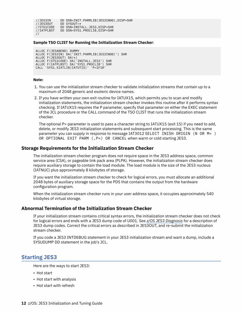
//JES3IN DD DSN=INIT.PARMLIB(JES3IN00),DISP=SHR//JES3OUT DD SYSOUT=*//STG1CODE DD DSN=INSTALL.JES3,DISP=SHR//IATPLBST DD DSN=SYS1.PROCLIB,DISP=SHR//
Sample TSO CLIST for Running the Initialization Stream Checker:
ALLOC F(JESABEND) DUMMYALLOC F(JES3IN) DA('INIT.PARMLIB(JES3IN00)') SHRALLOC F(JES3OUT) DA(*)ALLOC F(STG1CODE) DA('INSTALL.JES3') SHRALLOC F(IATPLBST) DA('SYS1.PROCLIB') SHRCALL 'SYS1.SIATLIB(IATUTIS)' 'P=1F1R'
Note:
1. You can use the initialization stream checker to validate initialization streams that contain up to amaximum of 2048 generic and esoteric device names.
2. If you have written your own exit routine for IATUX15, which permits you to scan and modifyinitialization statements, the initialization stream checker invokes this routine after it performs syntaxchecking. If IATUX15 requires the P parameter, specify that parameter on either the EXEC statementof the JCL procedure or the CALL command of the TSO CLIST that runs the initialization streamchecker.
The optional P= parameter is used to pass a character string to IATUX15 (exit 15) if you need to add,delete, or modify JES3 initialization statements and subsequent start processing. This is the sameparameter you can supply in response to message IAT3012 SELECT INISH ORIGIN (N OR M= )OR OPTIONAL EXIT PARM (,P=) OR CANCEL when warm or cold starting JES3.
Storage Requirements for the Initialization Stream CheckerThe initialization stream checker program does not require space in the JES3 address space, commonservice area (CSA), or pageable link pack area (PLPA). However, the initialization stream checker doesrequire auxiliary storage to contain the load module. The load module is the size of the JES3 nucleus(IATNUC) plus approximately 8 kilobytes of storage.
If you want the initialization stream checker to check for logical errors, you must allocate an additional2048 bytes of auxiliary storage space for the PDS that contains the output from the hardwareconfiguration program.
When the initialization stream checker runs in your user address space, it occupies approximately 540kilobytes of virtual storage.
Abnormal Termination of the Initialization Stream CheckerIf your initialization stream contains critical syntax errors, the initialization stream checker does not checkfor logical errors and ends with a JES3 dump code of U001. See z/OS JES3 Diagnosis for a description ofJES3 dump codes. Correct the critical errors as described in JES3OUT, and re-submit the initializationstream checker.
If you code a JES3 INTDEBUG statement in your JES3 initialization stream and want a dump, include aSYSUDUMP DD statement in the job's JCL.
Starting JES3Here are the ways to start JES3:
• Hot start• Hot start with analysis• Hot start with refresh
12 z/OS: JES3 Initialization and Tuning Guide

• Hot start with refresh and analysis• Warm start• Warm start with analysis• Warm start to replace a spool data set• Warm start with analysis to replace a spool data set• Cold start• Local start (used to start local mains only)
The type of start you select depends on why you need to start or restart JES3. The rest of this topicdiscusses the purpose of each type of start, what it does, and when you should use it. See z/OS JES3Commands for information on how to perform each type of start.
Hot StartUse a hot start to start JES3 on the global:
• After an orderly shutdown• After a JES3 failure on the global from which JES3 cannot automatically recover• After an MVS failure that terminates all functions in the global• To replace one of your checkpoint data sets.
JES3 does not read the initialization stream during a hot start. Instead, JES3 initializes itself by using theparameter values established during the previous cold or warm start. In addition, certain changes madeby the operator after the previous restart remain in effect. For a list of these changes, see z/OS JES3Commands.
If you perform an IPL of MVS before the hot start, JES3 restarts jobs that were running on the global andare eligible for restart. If a job is not eligible for restart, JES3 processes it based on the job's failureoptions. For an explanation of the failure options, see the FAILURE parameter on the CLASS initializationstatement. JES3 also restarts all FSSs that were running on the global and reschedules all jobs that wereactive in the FSS at the time of the IPL. If you do not perform an IPL of MVS before the hot start, all jobsand FSSs that were running before the hot start continue to run after the hot start. During a hot start,JES3:
• Examines the job queue to verify that it can restart each job• Prompts the operator if it locates a job that contains invalid control information• Removes jobs that contain invalid control information• Records the job control information associated with the removed jobs (they are recorded in the data setdefined by the //JES3SNAP DD statement)
• Continues to process valid jobs that were in the job queue before the hot start. Internal job numberingresumes with the next available job number.
Jobs and FSSs running on locals before the hot start continue to execute after the hot start. Any changesto the definition of an FSS brought about by using the *MODIFY operator command before the hot startremain in effect across a hot start with or without an IPL of MVS. Overflow partition relationships,including any changes brought about by using the *MODIFY operator command before the hot start, alsoremain in effect across a hot start.
Hot Start with AnalysisUse hot start with analysis after a hot start fails or you suspect problems with the JES3 job queue. A hotstart with analysis performs the same functions as a hot start. In addition, JES3 also:
• Performs further job validation• Gives the operator an opportunity to delete invalid jobs.
You are not required to IPL or to restart the local mains, although you may optionally do so.
Initializing JES3 13

Hot Start with RefreshUse hot start with refresh when you want to change the initialization stream without having to IPL theentire complex.
Performing a hot start with refresh avoids disrupting your system because you need only restart the JES3global address space. You do not need to IPL all processors in the complex like you do with a warm start.
JES3 is automatically restarted on all local processors that are at least at OS/390 Version 2 Release 9JES3. (For this topic, any processor that is not OS/390 Version 2 Release 9 JES3 is termed a down levelprocessor.). An IPL on processors at OS/390 Version 2 Release 9 JES3 is not required, although you mayoptionally do so. If you have added, deleted, or changed any SETNAME statements or DEVICE XUNITs,you must restart JES3 on all down level processors. You may need to IPL down level processorsdepending on how many of these changes you have made because they were last IPLed. If you haveadded, deleted, or changed any DYNALDSN statements you must IPL all down level processors. If youhave not made any changes to SETNAME or DYNALDSN statements or DEVICE XUNIT parameters, youneed not IPL or restart JES3 on down level processors although you may optionally do so.
During a hotstart with refresh, JES3 processes only those statements that can be changed. Thosestatements and parameters that cannot be changed are checked for syntax errors, and the informationfrom the previous warm or cold start is used. If a hot start with refresh fails, a subsequent hot start willreinstate the configuration from the last successful hot start with refresh, warm start, or cold start.
The initialization statements listed below in Table 3 on page 14, are the ones you can change, add, ordelete during a hot start with refresh.
Table 3: Modifiable JES3 Initialization Statements for Hot Start with Refresh
Statement Statement Statement Statement
ACCOUNT BUFFER CIPARM CLASS
COMMDEFN COMPACT CONSOLE DEADLINE
DESTDEF DEVICE DYNALLOC DYNALDSN
FSSDEF GROUP HWSNAME INCLUDE
INTDEBUG MSGROUTE NJECONS MAINPROC
NETSERV NJERMT OPTIONS OUTSERV
RESCTLBK RESDSN RJPLINE RJPTERM
RJPWS SELECT SETACC SETNAME
SETPARAM SETRES SOCKET STANDARDS
SYSID SYSOUT
You need to be careful when changing the initialization stream during a hot start with refresh, because notall of the initialization statements are processed. If you add or change one of the initialization statementsthat is not processed during a hot start with refresh, errors can occur when it is referenced by anotherinitialization statement that is processed during a hot start with refresh. The examples that follow showerrors that can occur during a hot start with refresh, because of dependencies between statements thatcan and cannot be changed.
• Example
You add a new SPART initialization statement to your initialization stream and change the SPARTparameter of a SYSOUT statement to reference the new spool partition. During initialization, JES3issues message IAT3222 to indicate that an incorrect spool partition was specified; this happens duringa hot start with refresh, because SPART statements are ignored and the SPART statements from theprevious warm or cold start are used. The new SPART statement you added is ignored. The errormessage is issued when the SYSOUT statement references the new SPART statement.
14 z/OS: JES3 Initialization and Tuning Guide

Note:
1. You must restart C/I FSS address spaces if you changed initialization statements or parameters thatC/I FSS address spaces use (for example, CIPARM, HWSNAME, REDSN, and SETNAME).
2. If a hot start with refresh fails, the old configuration remains in effect. A subsequent JES3 hot startreinstates the configuration from the last successful hot start with refresh, warm start, or cold start.
3. If you perform an IPL of MVS before the hot start with refresh, JES3 restarts jobs that were running onthe global and that are eligible for restart. If a job is not eligible for restart, JES3 processes it based onthe job's failure options. (See the FAILURE parameter on the CLASS initialization statement for details.)JES3 restarts all FSSs that were running on the global and reschedules all jobs that were active in theFSS at the time of the IPL. If you do not perform an IPL of MVS before the hot start, all jobs and FSSsthat were running before the hot start with refresh continue to run after the hot start with refresh.
4. Jobs and FSSs running on locals before the hot start with refresh continue to run after the hot startwith refresh. The following table shows whether changes to the definition of an FSS (made by using the*MODIFY operator command) remain in effect across a hot start with refresh.
Table 4: Hot Start With Refresh - Effect on FSSs
Status of the SystemWhere the FSS Runs
Is theSystemIPLed ?
Effect on FSS
Not Active N/A The FSSDEF statement overrides the changes.
Global No Changes remain in effect.
Local No Changes remain in effect.
Global Yes The FSSDEF statement overrides the changes.
Local Yes Changes remain in effect.
5. Overflow partition relationships, including any changes caused by using the *MODIFY operatorcommand before the hot start with refresh, remain in effect across a hot start with refresh.
6. See the Functional Summary tables in z/OS JES3 Initialization and Tuning Reference for more specificinformation on modifying initialization statements during a hot start with refresh.
7. A hot start with refresh will undo many of the changes made by operator commands that are related toinitialization statements. For example, most parameters on the *MODIFY,G command will no longer bein effect after a hot start with refresh; the information from the initialization statements will be used.See z/OS JES3 Commands for those commands and parameters that do not remain in effect during ahot start with refresh.
Hot Start with Refresh and AnalysisUse hot start with refresh and analysis after a hot start with refresh fails or you suspect problems with theJES3 job queue. A hot start with refresh and analysis performs the same functions as a hot start withrefresh. In addition, JES3 also:
• Performs further job validation• Gives the operator an opportunity to delete invalid jobs.
For restart of local mains, see Note “4” on page 15.
Initializing JES3 15

Warm StartUse a warm start to restart JES3 on the global:
• After either type of hot start or hot start with refresh fails.• After a failure of the global because of a software/hardware failure.• When you want to change the initialization stream and the changes cannot be performed with a hot start
with refresh.• Following the construction of the MVS Base Control Program.
During a warm start, JES3 reads and processes the initialization stream, saves jobs that are in the jobqueue, and terminates active jobs according to the job's failure options.
After a warm start, you must IPL and then restart all local processors. All FSS address spaces terminate atIPL time and are restarted by JES3 after IPL. JES3 then reschedules all jobs that were active in the FSSaddress space at the time of warm start. Any changes to the definition of an FSS address space broughtabout by using the *MODIFY operator command before the warm start are lost. JES3 continues to processjobs that were in the job queue at the time of the warm start.
Although you can change the initialization stream, use caution when changing the following statements:
• BUFFER• CLASS• DEVICE• FORMAT• MAINPROC• OPTIONS• SETNAME• TRACK
See the Statement Summary charts that precede each initialization statement in z/OS JES3 Initializationand Tuning Reference for restart modification considerations for each of the statements listed above.
Warm Start with AnalysisUse warm start with analysis when JES3 terminates abnormally and you suspect problems with the JES3job queue, or when you change the level of JES3 and want to verify the integrity of the JES3 job queueacross the change.
Warm start with analysis performs the same functions as warm start. In addition JES3:
• Removes jobs that have control information that contain invalid data from the job queue• Records job control information that is associated with the removed jobs (they are recorded in the data
set defined by the statement //JES3SNAP)
After performing a warm start with analysis, you must perform an IPL of MVS and then restart (local start)all local mains.
Warm Start to Replace a Spool Data SetUse warm start to replace a spool data set when you want to replace a spool data set. This type of startperforms the same function as a warm start in addition to allowing you to replace a spool data set.
After performing a warm start to replace a spool data set, you must perform an IPL of MVS and thenrestart (local start) all local mains. See “Replacing a Spool Data Set” in Chapter 6, “Defining and ManagingSpool Data Sets,” on page 159 for information on how to replace a spool data set using a warm start.
16 z/OS: JES3 Initialization and Tuning Guide

Warm Start with Analysis to Replace a Spool Data SetUse warm start with analysis to replace a spool data set when you suspect problems with the JES3 jobqueue and you want to replace a spool data set. This type of start performs the same function as a warmstart. In addition, you can replace a spool data set and JES3:
• Removes from the job queue all jobs that have invalid control information• Records job control information associated with the removed jobs (they are recorded in the data setdefined by the statement //JES3SNAP)
After performing a warm start with analysis to replace a spool data set, you must IPL MVS, then restart(local start) all local mains.
Cold startUse a cold start to start JES3 on the global:
• When all types of warm starts are unsuccessful.• When you want to change the size of the job control table data set (JCT), move the JCT to a device of a
different device type, or relocate the JCT to a device of the same device type.
You can avoid a cold start in this case by using the JCT Utility, IATUTJCT, to copy the contents of yourold JCT data set to a new JCT data set. See “JCT Utility (IATUTJCT)” on page 210 for more informationon the JCT Utility. You cannot use any other utility to do this copy because the JCT data set containsinformation that is dependent on the volume and the location on that volume where the data setresides.
• When you have changed the BUFSIZE parameter on the BUFFER initialization statement.• When you have changed the SE parameter on the OPTIONS statement.• When you have changed the STT or STTL parameter on a TRACK or FORMAT statement and want the
change to become effective immediately for existing spool data sets.• When you have changed the sequence of MAINPROC statements. (You can add statements to the end of
the sequence or delete statements from the end of the sequence without doing a cold start.).
During a cold start, JES3 reads and processes the initialization stream. JES3 also removes all jobs (jobsthat were active and jobs that were in the job queue at the time of the cold start) from the system. Thus,you must resubmit all jobs after a cold start.
All FSSs terminate at IPL time. Any changes to the definition of an FSS brought about by using the*MODIFY operator command before the cold start are lost. To restart a C/I FSS after a cold start, you musthave specified START=YES on its FSSDEF statement or you must issue the*MODIFY,F,FSSNAME=fssname,ST=YES operator command.
If JES3 is running properly before the cold start, you can save jobs by using the dump job (DJ) facility andthen restore them after the cold start has been performed. This facility is described in z/OS JES3Commands.
Table 5 on page 18 summarizes the types of starts you can use to start the global. This figure uses thefollowing mnemonics to identify each start type:
• Hot start (H)• Hot start with analysis (HA)• Hot start with refresh (HR)• Hot start with refresh and analysis (HAR)• Cold start (C)• Warm start (W)• Warm start with analysis (WA)• Warm start to replace a spool data set (WR)• Warm start with analysis to replace a spool data set (WAR)
Initializing JES3 17

Table 5: Characteristics of Global Processor Starts.
Characteristics H HA HR HAR W WA WR WAR C
Retains Job Queue Y Y Y Y Y Y Y Y N
Read Init. Stream N N Y Y Y Y Y Y Y
Spool Data Lost N N N N N N N N Y
Replace Spool Data Set N N N N N N Y Y Y
Reinstate Spool Data Set Y Y Y Y Y Y Y Y Y
Remove Spool Data Set Y Y Y Y Y Y Y Y Y
Add Spool Data Set N N N N Y Y Y Y Y
IPL Global O O O O R R R R R
IPL Locals O O O O R R R R R
Job Disposition (see notes) 1,2 1,2,5 1,2 1,2,5 4 4,5 4 4,5 3
1.If you do not perform an IPL on the global processor, jobs that were running at the time of the hot startcontinue to execute.
2.If you perform an IPL on the global processor, JES3 restarts jobs that are eligible for restart and wererunning at the time of the hot start. JES3 processes jobs that are not eligible for restart according to thejob's failure options.
3.All jobs must be resubmitted.
4.JES3 restarts jobs that are eligible for restart. JES3 processes jobs that are not eligible for restart accordingto the job's failure option.
5.JES3 removes jobs that could cause a restart failure from the job queue and records control blocks that areassociated with the job.
KEYY=yes, N=no, O=optional, R=required
Local startUse a local start to start JES3 on a local main:
• After a cold start or any type of warm start on the global.• After JES3 fails on the local.• After a processor complex has been partitioned.
After a cold start or any type of warm start, initialization of the global must be complete before you canstart or restart a local main. If you do not automatically start JES3 as part of the MVS IPL, you can use theROUTE *OTHER command to start JES3 on all the local processors simultaneously when those processorshave joined the sysplex.
JES3 does not read the initialization stream to initialize a local. Instead, the global provides theinitialization values that it read from the initialization stream during the last cold start, warm start, or hotstart with refresh.
18 z/OS: JES3 Initialization and Tuning Guide

Before using a local start on a partition of a processor complex, make sure that the main representing thatpartition is stopped. If the main is not inactive, spool damage could result.
If you do not perform an IPL of MVS on the local, jobs and FSSs that were active at the time of the localstart continue to execute. If you do perform an IPL, JES3 processes jobs that were active according to thejob's failure options. You must also restart any dynamic support programs that were running on a localmain before an IPL. At the time the local is connected to the global, JES3 on the global restarts FSSaddress spaces that were active on the local before the local start.
For a local start with or without an IPL, changes to the definition of an FSS address space brought aboutby using the *MODIFY operator command remain in effect. The local start does not affect FSSs running onother mains.
Tuning JES3You can affect how JES3 performs. Factors that you should consider when tuning JES3 are:
• Hardware used• Availability of resources• JES3 work load• Job processing options selected
You should develop a set of performance objectives that state what you expect of JES3. After you developperformance objectives and install JES3, you can tune it. For guidelines about how to tune JES3, see thesection of this document that describes the JES3 function or the specific resource you want to tune.
Tuning is not a task that you perform only once. It is an iterative process; you measure the performanceand make adjustments, measure the performance, make additional adjustments, and so forth. You canuse the following facilities to collect data and measure the performance of JES3 and MVS:
• The JES3 Monitoring Facility (JMF)• The MVS Resource Monitoring Facility (RMF™)• The MVS System Monitoring Facility (SMF)• JES3 Commands
This document refers to the reports produced by JMF and RMF, and records produced by SMF whereapplicable. Refer to RMF Monitor I and II Reference Summary for descriptions and examples of RMFreports and z/OS MVS System Management Facilities (SMF) for descriptions and examples of SMFrecords.
JES3 MonitoringJES3 monitors its functions while it is operational. JES3 checks for any unusual conditions and reportsthem to the operator through operator messages to the console. The operator can then take correctiveactions based on the error messages.
The messages are issued periodically while the condition persists. This is based on the function involved.In some cases the frequency of the messages can either be controlled by an operator command orthrough a response to a Write-to-Operator (WTOR).
JES3 also provides exceptional checking on request while JES3 is running or offline during dump analysis.For more detail on JES3 monitoring and checking see Chapter 12, Automatic monitoring of JES3functions, in z/OS JES3 Commands.
Using JMF to Measure JES3 PerformanceThe JES3 Monitoring Facility (JMF) is a JES3 diagnostic and performance utility that you can use to helpmonitor, diagnose, and tune your JES3 complex. You can use JES3 operator commands to produce JMFreports that contain data about:
Initializing JES3 19

• JES3 spool data management• JES3 CPU/storage• JES3 functions• JES3 device scheduling• JES3 job throughput
Since JMF measurements vary from installation to installation, you must first establish your own baselinemeasurements by running JMF over a period of time under normal operating conditions. See z/OS JES3Diagnosis for sample JMF reports and the commands that you need to generate those reports.
Using JES3 Auxiliary Address Space (JES3AUX)Before z/OS V1R8 JES3, the JES3AUX address space was started only when the PRTPAGE= parameter onthe MAINPROC statement included a nonzero auxpages subparameter. Starting with z/OS V1R8 JES3,JES3AUX is started at all time.
JES3AUX provides an alternate place to allocate protected page buffers to optionally reduce thedependence of JES3 on ECSA for these buffers. See Chapter 8, “Defining and Managing JES3 Resources,”on page 201 for more information. In addition, JES3 uses the JES3AUX address space for the followingpurposes, even when auxpages is zero:
• The JES3AUX address space provides a cross memory post for JES3 after an I/O request fails.• The JES3AUX address space provides a space switching PC routine to make unauthorized application
code capable of using various types of Subsystem Interface calls.• The JES3AUX address space provides support for the Multi-System Core Buffer Function.
Note: Correcting an abend that is reported by the Core Buffer support code can require an IPL of themain processor that issued the abend.
Maintaining JES3
JES3 Maintenance philosophyMaintaining JES3 is a periodic activity. As you receive updates or enhancements for your JES3 product,you must apply these updates to your JES3 component. Although IBM delivers JES3 and MVS services inthe same manner, how you install each service can differ.
To minimize the impact of applying maintenance while maintaining continuous operations, you mustunderstand the JES3 maintenance philosophy. Follow the JES3 maintenance philosophy when applyingAPARs/PTFs, which fix problems that can arise between your scheduled maintenance upgrades, using thePUT maintenance process.
When installing JES3 APARs/PTFs, terminology is used which is explained in the following sections. Theintent is to limit the number of complex-wide restarts required by installing JES3 APARs/PTFs. Note thatthe restart information does not take into account a dynamic system interchange (DSI). Therefore, if youuse a DSI, be aware that the term "GLOBAL" implies both the current GLOBAL processor and all potentialGLOBAL processors.
General overview of JES3 service
To maintain your JES3 component, you must understand how JES3 structures its maintenance in aSystem Modification Program (SMP) environment. It is assumed that you are familiar with the terminologyand operation of SMP. Refer to SMP/E for z/OS User's Guide for more information on using SMP.
JES3 is a source-maintained product, which means that corrective fixes (APARs) are distributed in sourceformat, while preventive fixes (PTFs) are distributed in source (non-cumulative) and object code format. Itis an SMP requirement that every new fix (SYSMOD) must either PRE-REQ (prerequisite) or SUP
20 z/OS: JES3 Initialization and Tuning Guide

(supersede) all previous maintenance to the same module. In this way, SMP can ensure that no previousservice is dropped or regressed. For example, assume that PTF1 addresses a problem in moduleIATOSWD, which is the permanent fix for APAR1. APAR2 is then created to address another problem inthe same module, IATOSWD. PTF2, created for for APAR2, must then PRE-REQ or SUP PTF1, becauseboth PTF1 and PTF2 apply to the same module, IATOSWD.
JES3 APARs, however, do not follow this same SMP requirement. A JES3 APAR only PRE-REQs or SUPsthe code (APAR) that is required to allow the fix to function correctly. JES3 APARs never PRE-REQ or SUPPTFs. Applying APARs in this manner allows the user to install APAR maintenance to the systemregardless of the existing PTF level that is currently installed.
During the application of JES3 APARs, SMP SYSMOD regression reports can indicate that other SYSMODsare being regressed. This regression occurs because the APAR did not PRE-REQ or SUP the previouslyapplied maintenance PTF. Each regression error message indicates the specific APAR that is doing theregress and the specific PTF that was previously applied. Regression error messages, GIM38201W andGIM31901I, issued during the application of JES3 APARs can be ignored when they list PTFs. You mustnot ignore these messages if they list APARs, and you must not ignore any other error messages.
During the application of JES3 PTFs, regression error messages can be issued. If the regressed SYSMOD isanother PTF, then the PTF currently being applied may be in error, or the already installed PTFs have beenerroneously applied. In either case, you must determine why the regression message was issued. If theSYSMOD being regressed is an APAR, the APAR needs to be restored, the new PTF applied, then the APARreapplied. Instead of giving you the choice to restore the APAR, SMP allows you to ACCEPT the APAR.JES3, however, recommends that APARs never be accepted. Do not ignore any SMP error messages whenprocessing PTFs.
Note: For various reasons, FIXTEST APARs are provided to allow JES3 users to verify the fix before theformal PTF is distributed. JES3 assumes that the APAR fix is only APPLIED and never ACCEPTED by SMP,because the final fix can change based on the feedback received from the testing customers. You mustremove the FIXTEST version prior to application of the final APAR or PTF to avoid conflicts with the finalfix.
JES3 restart information
After APAR or PTF maintenance has been applied to your JES3 system, you must determine how JES3 isto be restarted. Each JES3 APAR and PTF includes installation and activation information that define thetype of JES3 and MVS restarts that are required to properly install the changes made by the APAR or PTF.The information provided takes into account module residency, operating environment, and how thechange interacts with control blocks and other data structures created before the installation of thechange. This restart information must be followed to ensure proper implementation of the changes.
JES3 service will inform you of the processors that the APAR or PTF must be installed on, the order ofinstallation, the order of activation, the type of JES3 restart required, the type of IPL required, andwhether or not CLPA is required. For example, the cover letter information found in the APAR will containinstructions similar to the following in the PROBLEM CONCLUSION:
• Install on (All processors)• Order of installation (Any)• Order of activation (Any)• Type of JES3 restart (None)• Type of IPL (Rolling), CLPA (Yes)
The following values can be specified for this information:
RESTART Information - Install OnThis information describes which processors the APAR must be installed on. This processor can onlybe one of the following:All processors with C/I FSS
All processors in the complex with C/I FSS address spaces.
Initializing JES3 21

All processors with WTR FSSAll processors in the complex with WTR FSS address spaces.
All processors with any FSSAll processors in the complex with any FSS address spaces.
All processors with a NetservAll processors in the complex that run a Netserv.
LocalsAll local processors in the complex.
GlobalThe global processor and all potential global processors in the complex.
All processorsAll processors in the complex regardless of whether C/I or WTR FSS is active on the processor.
RESTART Information - Order of InstallationThis information describes the order that the APAR must be installed. This order can be one of thefollowing:ANY
The order of installation does not matter.Global first, then locals
Install on the global processor first, then install on all local processors in the complex.Locals first, then Global
Install on all local processors in the complex first, then install on the global processor.RESTART Information - Order of Activation
This information describes the order that the APAR must be activated. This order can be one of thefollowing:ANY
The order of activation does not matter.Global first, then locals
Activate on the global processor first, then activate on all local processors in the complex.Locals first, then Global
Activate on all local processors in the complex first, then activate on the global processor.RESTART Information - Type of JES3 Restart Required
This information describes the type of JES3 restart that is required. This restart can be one of thefollowing:
Note: To pick up a new level of the modules, you must do one of the following:
• IPL the processor• If an IPL is not required, issue an F LLA,REFRESH or F LLA,UPDATE command.
NONENo JES3 restart is needed.
HOTPerform a hot start of the JES3 address space on the global processor.
HOT/REFRESHPerform a hot start with refresh of the JES3 address space on the global processor.
WARMRe-IPL all processors in the complex. Perform a warm start of the JES3 address space on theglobal processor. Perform a local start of all local processors in the complex.
LOCALPerform a local start of all local processors in the complex.
C/I FSSTerminate and restart all C/I FSS address spaces in the complex.
22 z/OS: JES3 Initialization and Tuning Guide

WTR FSSTerminate and restart all WTR FSS address spaces in the complex.
ANY FSSTerminate and restart all FSS address spaces in the complex.
NetservCancel and restart all Netservs in the complex.
HOT/COMMANDThe new level of the code can be activated by issuing a MODIFY LLA,REFRESH/UPDATE orMODIFY LLA,UPDATE=xx command, and then issuing a *MODIFY,X,M=modname,REFRESHcommand for each module shipped in the APAR. The *MODIFY,X command will delete the oldversion of the module and cause a new copy of the module to be loaded the next time it is used.MSGIAT8489 stating Refresh Pending indicates the new copy of the module cannot be loadeduntil all DSPs using it are stopped.
No IPL RequiredIn cases where you do not need to IPL and instead just restart the JES3 address space, issue a*MODIFY,X command to refresh the module within JES3 (or use the SETPROG command forDynamic LPA). You still need to issue a MODIFY LLA,REFRESH or MODIFY LLA,UPDATEcommand first.
RESTART Information - Type of IPL RequiredThis information describes whether an IPL is required. If an IPL is required, this information indicateswhich systems should be IPLed after installing the APAR. This information can be one of the following:NONE
No IPL is required.ROLLING
IPL one processor at a time until all processors in the complex have been IPLed.GLOBAL
IPL the global processor only.LOCAL
IPL the local processors only.GLOBAL TO LOCAL
IPL the global processor first, then IPL the local processors.LOCAL TO GLOBAL
IPL the local processors first, then IPL the global processor.ROLLING/DynLPA
You can activate the change using the dynamic LPA facility and then perform a hot or local startwithout an IPL of the required processors. See Dynamic LPA Facility for more information.
GLOBAL/DynLPAYou can activate the change using the dynamic LPA facility and then perform a hot start without anIPL of the global processor. See Dynamic LPA Facility for more information.
LOCAL/DynLPAYou can activate the change using the dynamic LPA facility and then perform a local start withoutan IPL of the local processors. See Dynamic LPA Facility for more information.
Dynamic LPA Facility
New versions of JES3 LPA modules can be dynamically added to LPA by issuing the followingcommands:
F LLA,REFRESH
followed by:
SETPROG LPA,ADD,MODNAME=IATSICA,DSN=LNKLST
Initializing JES3 23

These commands can be issued while JES3 is active. The change does not take effect until JES3 isrestarted. This allows you to back out the change if necessary.
If the fix must be installed on more than one system, a SETPROG command must be issued foreach system.
Once the required modules have been added to LPA, perform a hot start or local start of JES3(without an IPL of the system) to activate the change. During initialization, JES3 picks up the newversions of the modules and issues the following:
IAT3085 LPA MODULES CHANGED: IATSICA ...
On the JES3 global processor, the prior message appears in JES3OUT only. On the JES3 localprocessors, the prior message appears on the console.
ComplexIPL all processors at the same time.
Restart Information - CLPA requiredThis information describes whether a CLPA (create link pack area) is required when the system isIPLed after installing the APAR. The information can be as follows:YES
Perform a CLPA.NO
No CLPA is required.
Running JES2 and JES3 on the same image is not supportedRunning JES2 and JES3 on the same image (system) is not supported. APARs are not accepted forproblems caused by the interaction of the JES components for this environment. This refers toconfigurations where JES3 is the primary subsystem and JES2 is started with either SUB=MSTR orSUB=JES3.
Dynamically changing the JES3 configurationYou can make changes to the JES3 configuration dynamically after the system has been initialized and isrunning by using the *MODIFY,CONFIG operator command.
The *MODIFY,CONFIG command allows you to add the following definitions to JES3 without having torestart the JES3 global and local address spaces:
• SNA RJP work stations and their associated consoles and devices• Non-channel attached printers
You use *MODIFY,CONFIG to specify the name of a member in the data set allocated to the JES3IN DDstatement in the JES3 cataloged start procedure. This member contains the initialization statementsassociated with definitions that you want added to the JES3 configuration. The following initializationstatements can be coded in the member specified on the *MODIFY,CONFIG command:
• RJPWS to define SNA/RJP workstation characteristics• CONSOLE to define SNA/RJP console• DEVICE to define SNA/RJP devices and non-channel attached FSS managed printers• FSSDEF to define writer FSSs• INTDEBUG to establish the Initialization Debugging Facility• INCLUDE to include another initialization stream member
Note: If the JES3IN DD data set is concatenated, only the members in the first data set of theconcatenation are used in processing the INCLUDE statement.
• DYNALLOC to dynamically allocate data sets
24 z/OS: JES3 Initialization and Tuning Guide

• BUFFER to define buffer spool parameters• FORMAT to format data sets on a direct-access spool volume• TRACK to define a pre-formatted data set on a direct-access spool volume, or to replace a
corresponding FORMAT statement• SPART to define a spool partition• OPTIONS to specify dump and job parameters• ENDJSAM to indicate the end of JES3 spool initialization statements.
Notes:
1. The statements are checked for syntax but not all parameters are applied. See the statementdescriptions in the z/OS JES3 Initialization and Tuning Guide for the parameters that are modifiable byusing *MODIFY CONFIG.
2. *MODIFY,CONFIG can only be used to dynamically change statements in the JSAM portion of theinitialization stream (DYNALLOC, BUFFER, FORMAT/TRACK, SPART, and OPTIONS) as part of an updatethat includes the entire JSAM portion of the initialization stream, up to and including the ENDJSAMstatement.
If you intend to dynamically add or delete spool volumes, you should create a separate initializationstream member that contains the JSAM related statements (the spool initialization statements, up to andincluding ENDJSAM). This member can be specified on a *MODIFY,CONFIG command. Use the INCLUDEstatement in your JES3INxx member to ensure that the same configuration is used during anysubsequent JES3 starts that read the initialization stream.
*MODIFY,CONFIG command processing occurs in three stages:Statement Syntax Checking
This process checks the statements for validity and issues error messages if they contain errors. Thisstage only checks for errors on the statement; it does not check for cross-statement dependencies. Atthe end of this stage, you can look at the log that was generated, and cancel *MODIFY,CONFIGprocessing if there are errors.
Cross Checking/Table BuildThis process checks for cross statement dependencies (for example, was a CONSOLE defined for anRJPWS), and builds the tables to represent the definitions being added; it issues error messages if thedefinitions contain errors.
CommitThis process updates the JES3 configuration with the new definitions; these definitions are now activein the JES3 configuration. If you perform a hot start, the changes you made through the*MODIFY,CONFIG command remain in effect.
The following examples illustrate how you would edit a member to:
1. Add an FSS managed printer (Figure 4 on page 26).2. Add a SNA/RJP work station and its devices (Figure 5 on page 26).
Initializing JES3 25
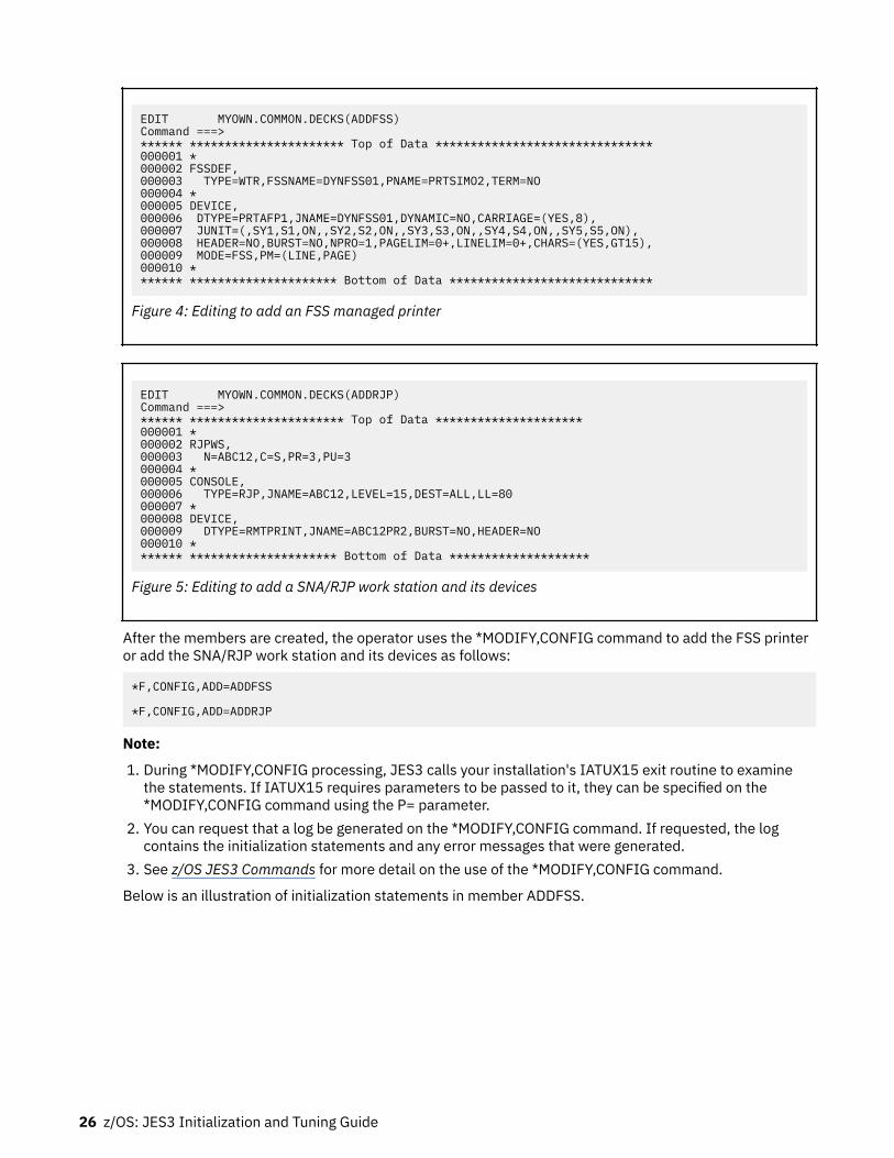
EDIT MYOWN.COMMON.DECKS(ADDFSS)Command ===>****** ********************** Top of Data *******************************000001 *000002 FSSDEF,000003 TYPE=WTR,FSSNAME=DYNFSS01,PNAME=PRTSIMO2,TERM=NO000004 *000005 DEVICE,000006 DTYPE=PRTAFP1,JNAME=DYNFSS01,DYNAMIC=NO,CARRIAGE=(YES,8),000007 JUNIT=(,SY1,S1,ON,,SY2,S2,ON,,SY3,S3,ON,,SY4,S4,ON,,SY5,S5,ON),000008 HEADER=NO,BURST=NO,NPRO=1,PAGELIM=0+,LINELIM=0+,CHARS=(YES,GT15),000009 MODE=FSS,PM=(LINE,PAGE)000010 ******* ********************* Bottom of Data *****************************
Figure 4: Editing to add an FSS managed printer
EDIT MYOWN.COMMON.DECKS(ADDRJP)Command ===>****** ********************** Top of Data *********************000001 *000002 RJPWS,000003 N=ABC12,C=S,PR=3,PU=3000004 *000005 CONSOLE,000006 TYPE=RJP,JNAME=ABC12,LEVEL=15,DEST=ALL,LL=80000007 *000008 DEVICE,000009 DTYPE=RMTPRINT,JNAME=ABC12PR2,BURST=NO,HEADER=NO000010 ******* ********************* Bottom of Data ********************
Figure 5: Editing to add a SNA/RJP work station and its devices
After the members are created, the operator uses the *MODIFY,CONFIG command to add the FSS printeror add the SNA/RJP work station and its devices as follows:
*F,CONFIG,ADD=ADDFSS
*F,CONFIG,ADD=ADDRJP
Note:
1. During *MODIFY,CONFIG processing, JES3 calls your installation's IATUX15 exit routine to examinethe statements. If IATUX15 requires parameters to be passed to it, they can be specified on the*MODIFY,CONFIG command using the P= parameter.
2. You can request that a log be generated on the *MODIFY,CONFIG command. If requested, the logcontains the initialization statements and any error messages that were generated.
3. See z/OS JES3 Commands for more detail on the use of the *MODIFY,CONFIG command.
Below is an illustration of initialization statements in member ADDFSS.
26 z/OS: JES3 Initialization and Tuning Guide

* FSSDEF, Can't add a C/I FSS TYPE=CI,FSSNAME=DYNCIFSS,PNAME=JES3CI,START=YES,TERM=YES
FSSDEF, Duplicate FSS name as one defined above TYPE=WTR,FSSNAME=DYNFSS01,PNAME=PRTSIMO2,TERM=NO *
Figure 6: The ADDFSS member
When you issue the *MODIFY,CONFIG to add the C/I FSS, you get a log and error messages. Some errorsare detected in the syntax checking phase of processing and others errors are found in the table buildphase.
*** LOG OUTPUT ***
IAT8351 *MODIFY,CONFIG - DATE = 1997.140, TIME = 14.59.10
IAT8351 DSN = MYOWN.COMMON.DECKS , MEMBER = ADDFSS , PARMS =
FSSDEF, TYPE=WTR,FSSNAME=DYNFSS01,PNAME=PRTSIMO2,TERM=NO * DEVICE, DTYPE=PRTAFP1,JNAME=DYNFSS01,DYNAMIC=NO,CARRIAGE=(YES,8), JUNIT=(,SY1,S1,ON,,SY2,S2,ON,,SY3,S3,ON,,SY4,S4,ON,,SY5,S5,ON), HEADER=NO,BURST=NO,NPRO=1,PAGELIM=0+,LINELIM=0+,CHARS=(YES,G,T15), MODE=FSS,PM=(LINE,PAGE) * FSSDEF, Can't add a C/I FSS TYPE=CI,FSSNAME=DYNCIFSS,PNAME=JES3CI,START=YES,TERM=YESIAT3055 TYPE=CI FSSDEF STATEMENT CANNOT BE ADDED DYNAMICALLY
* FSSDEF, Duplicate FSS name as one defined above TYPE=WTR,FSSNAME=DYNFSS01,PNAME=PRTSIMO2,TERM=NO *IAT8348 WARNING LEVEL MESSAGE(S) ISSUED DURING INITIALIZATION PROCESSING *IAT3165 MULTIPLE FSS DEFINITIONS FOR FSS DYNFSS01
Figure 7: *MODIFY,CONFIG log for member ADDFSS - duplicate FSS names
After the *MODIFY,CONFIG command is processed, the appropriate tables are built to represent theinformation that was added. The changes you made are preserved across a JES3 hot start; you do nothave to issue another *MODIFY,CONFIG command. However, the changes are not preserved across a coldstart, warm start, or hot start with refresh so remember to add the initialization statements to yourinitialization stream.
You can use the INCLUDE statement to use the same members for both *MODIFY,CONFIG and JES3initialization. For example, suppose that the INCLUDE statement is used to group related initializationstatements into separate members, and the RJPWS and its related statements are in a member named"RJPWS". Also, suppose that your IATUX15 exit supports conditional logic to skip around statementsdepending on the parameter string passed to it. To add a new RJPWS definition, you would then do thefollowing:
1. Add the new RJPWS definition to the existing "RJPWS" member as illustrated below.
Initializing JES3 27

Figure 8: *MODIFY,CONFIG with IATUX15 exit processing2. Add conditional logic in the RJPWS member to process only the new statements when a
*MODIFY,CONFIG command is issued. You use the *IF and *LBL statements as in the example above.(This example assumes that IATUX15 has special code to recognize these statements.)
3. Issue the following *MODIFY,CONFIG command:
*MODIFY,CONFIG,ADD=RJPWS,P=NEW
By specifying "P=NEW" on *MODIFY,CONFIG, the old RJPWS definitions are skipped and only the newRJPWS definitions are processed. Since the "RJPWS" member is included by the member JES3INxx,these new RJPWS definitions are automatically picked up the next time a hot start with refresh, warmstart, or cold start is performed. You do not have to update your initialization stream after issuing the*MODIFY,CONFIG command.
28 z/OS: JES3 Initialization and Tuning Guide

Chapter 3. Providing security for JES3
You can use initialization statements, JES installation exits, RACF®, or any other functionally equivalentproduct, to provide security for JES.
This section describes how to use RACF to provide security for JES. The term "JES" here refers to bothJES2 and JES3 except when there is a difference between the two. For additional information about RACFsupport for JES, see z/OS Security Server RACF Security Administrator's Guide.
Planning for SecurityWhile every installation may have a unique set of reasons to secure data system resources, the basicreason is to prevent unauthorized personnel or programs from accessing, modifying, copying, ordestroying valuable data or from damaging the system itself.
Table 6 on page 29 lists some of the common benefits that you can obtain for your installation byactivating security facilities for system resources:
Table 6: Benefits of Protecting JES3 Resources. Resource and Benefits
Resource Benefits
System data sets Prevents unauthorized users or jobs from accessing, modifying,copying, or destroying valuable system data.
SYSIN and SYSOUT data sets Prevents unauthorized users or jobs from reading, copying, printing,or destroying job data.
Job entry
• Job names• Input sources• RJP• NJE• Job classes
Prevents unauthorized users from entering jobs into the system withspecific job names and specific job classes, or entering jobs fromspecific ports of entry.
Console access Prevents unauthorized operators from gaining access to MCS or RJPconsoles.
Job output (writers) Prevents unauthorized users from sending output to specific devicesor remote locations.
Commands Prevents unauthorized operators from entering commands fromoperator consoles.
In addition to controlling access to resources, JES3, in conjunction with (system management facilities)SMF, provides the ability to audit specific actions on resources.
You and your JES system programmer should develop a security plan for JES. Together, you shoulddetermine which resources you want to protect and decide who should have access to those resources.Your security plan should address questions such as:
• What resources must I protect?• Should I restrict jobs and users from certain information depending on criteria such as security labels?• Should I limit the job names users can submit or cancel?
© Copyright IBM Corp. 1988, 2017 29

• Is it important to protect SYSIN and SYSOUT?• Which remote workstations should access my system?• Can other nodes submit jobs to my system?• To which nodes should I allow my system to send data?• Should I limit the commands an operator can use?• Do I want to restrict the consoles an operator can use to enter certain commands?• What commands will I allow jobs, workstations, and nodes to submit to my system?• Do I want only selected output devices to process particular output?• Should the security label of the output appear on the header pages?
If JES3 is installed on your system, the JES system programmer will be using the following documents:
• z/OS Introduction and Release Guide• z/OS Planning for Installation• z/OS JES3 Initialization and Tuning Reference• z/OS Security Server RACF Security Administrator's Guide• z/OS Security Server RACF General User's Guide
Using RACF to provide securityJES3 accesses RACF services through the MVS System Authorization Facility (SAF). Through SAF, JES3passes security information about jobs and resources to RACF, which evaluates the security informationand returns the results of that evaluation to JES3. JES3 then enforces the results of the security check,such as permitting or denying access to a data set or allowing a job to process. If RACF is inactive or notinstalled, SAF returns default security information to JES3. JES3 may or may not perform alternativesecurity processing depending on how you tailor your system through JES3 initialization statements orinstallation exits. See z/OS MVS Programming: Authorized Assembler Services Guide for additionalinformation about the SAF interface.
To activate RACF protection, have your security administrator enable the RACF class for each type ofresource that you want to protect. A RACF class is a collection of RACF-defined entities, such as data setsor devices, that have similar characteristics. In addition to activating RACF classes, the securityadministrator will typically also need to define RACF profiles that grant users access to these resources.Table 7 on page 30 lists the resources that you can protect, their corresponding RACF classes, and theRACF profile name format (which is sometimes referred to as an entity name) for each resource. Figure 9on page 32 shows a cross-section of a sample CLIST that contains RACF profiles.
For additional information about defining RACF classes and profiles, see z/OS Security Server RACFSecurity Administrator's Guide.
Table 7: RACF Classes Used to Protect JES3 Resources.
Resource: RACF Class: RACF Profile (Entity) Names:(1)
Access to system data sets that JES3 uses DATASET (alwaysactive)
data set name
Access to SYSIN and SYSOUT data sets JESSPOOL node.userid.jobname.jobid.dsnumber.dsname
Access to SYSLOG JESSPOOL node.+MASTER+.SYSLOG.*.*.?
Access to operator consoles CONSOLE console-id
Use of specific input sources (such as RJP,NJE, and readers)
JESINPUT(2) devicename
30 z/OS: JES3 Initialization and Tuning Guide

Table 7: RACF Classes Used to Protect JES3 Resources. (continued)
Resource: RACF Class: RACF Profile (Entity) Names:(1)
Use of output destinations WRITER jesname.LOCAL.devicenamejesname.RJP.devicenamejesname.NJE.nodename
Job submission from network nodes NODES node.keyword.name
Use of job names JESJOBS SUBMIT.node.jobname.useridCANCEL.nodename.userid.jobname
Use of job classes JESJOBSFACILITY JOBCLASS.localnodeid.jobclass.jobname
JES.JOBCLASS.OWNER (FACILITY)JES.JOBCLASS.SUBMITTER (FACILITY)
Use of printers DEVICES sysname.dev-class. modelno.devnum (or /devnum)
Use of commands (other than RJP/NJE) OPERCMDS jesname.command[.qualifier]
Use of commands (from RJP workstations) USER (always active)OPERCMDSFACILITY
workstationnamejesname.command[.qualifier] (OPERCMDS)RJE.workstationname (FACILITY)
Use of commands (from NJE nodes) USER (always active)OPERCMDSFACILITY
nodename jesname.command[.qualifier](OPERCMDS) NJE.node (FACILITY)
Ability to start a Network Server(NETSERV)
STARTED pattern.* (where pattern is a genericpattern that covers the NAME= parameteron the NETSERV statement).
Note:
1. One profile must exist in this class when the class is active or all jobs will fail.2. The name you specify for the variable jesname when creating RACF profiles is the name of your subsystem
as specified in the IEFSSNxx member of the MVS SYS1.PARMLIB data set. The name you specify for thesysname variable is specified in the IEASYSxx member of SYS1.PARMLIB.
Providing security for JES3 31

/**********************************************************************/26500000/* */26510000/* CREATE OPERATOR COMMAND PROFILES */26520000/* */26530000/**********************************************************************/26540000/*---------------------------------------------------------------*/ 26550000/* JES3 DSP FUNCTION COMMANDS */ 26560000/*---------------------------------------------------------------*/ 26570000 26580000RDEFINE OPERCMDS JES3.CALL.DR.* UACC(NONE) 26590000PERMIT JES3.CALL.DR.* CLASS(OPERCMDS) ID(OPER7 OPER21 OPER24) + 26600000 ACCESS(UPDATE) 26610000 26620000RDEFINE OPERCMDS JES3.CALL.* UACC(NONE) 26630000PERMIT JES3.CALL.* CLASS(OPERCMDS) ID(OPER7 OPER21 OPER24) + 26640000 ACCESS(UPDATE) 26650000 26660000RDEFINE OPERCMDS JES3.CANCEL.DEV.* UACC(NONE) 26670000PERMIT JES3.CANCEL.DEV.* CLASS(OPERCMDS) ID(OPER7 OPER21 OPER24) + 26680000 ACCESS(UPDATE) 26690000 26700000RDEFINE OPERCMDS JES3.CANCEL.* UACC(NONE) 26710000PERMIT JES3.CANCEL.* CLASS(OPERCMDS) ID(OPER7 OPER21 OPER24) + 26720000 ACCESS(UPDATE) 26730000 26740000RDEFINE OPERCMDS JES3.START.DR.* UACC(NONE) 26750000PERMIT JES3.START.DR.* CLASS(OPERCMDS) ID(OPER7 OPER21 OPER24) + 26760000 ACCESS(UPDATE) 26770000 26780000RDEFINE OPERCMDS JES3.START.DEV.* UACC(NONE) 26790000PERMIT JES3.START.DEV.* CLASS(OPERCMDS) ID(OPER7 OPER21 OPER24) + 26800000 ACCESS(UPDATE) 26810000 26820000RDEFINE OPERCMDS JES3.START.* UACC(NONE) 26830000PERMIT JES3.START.* CLASS(OPERCMDS) ID(OPER7 OPER21 OPER24) + 26840000 ACCESS(UPDATE) 26850000 /************************************************************/ 29940000 /* CREATE JES3 SPOOL DATA SET PROFILES */ 29960000 /************************************************************/ 29990000 30000000RDEFINE JESSPOOL NODE1.JES3.*.JOB00000.D0000000.JNEWSLCL UACC(READ) + 30010000 AUDIT(ALL) 30020000RDEFINE JESSPOOL NODE3.JES3.*.JOB00000.D0000000.JNEWSRJP UACC(READ) + 30030000 AUDIT(ALL) 30040000RDEFINE JESSPOOL NODE3.JES3.*.JOB00000.D0000000.JNEWSTSO UACC(READ) + 30050000 AUDIT(ALL) 30060000 30070000PERMIT NODE1.JES3.*.JOB00000.D0000000.JNEWSLCL CL(JESSPOOL) + 30080000 ACCESS(UPDATE) ID(OPER0 OPER24 TSOG0 SUPERU) 30090000PERMIT NODE2.JES3.*.JOB00000.D0000000.JNEWSRJP CL(JESSPOOL) + 30100000 ACCESS(UPDATE) ID(OPER0 OPER24 TSOG0 SUPERU) 30110000PERMIT NODE3.JES3.*.JOB00000.D0000000.JNEWSTSO CL(JESSPOOL) + 30120000 ACCESS(UPDATE) ID(OPER0 OPER24 TSOG0 SUPERU) 30130000
Figure 9: Sample Section of a CLIST that Defines RACF Profiles
How JES and RACF Work TogetherJES requests RACF services by issuing the RACROUTE macro. SAF processes the RACROUTE macroinvocation. If RACF is installed, SAF passes the security information specified by JES on the RACROUTEmacro invocation to RACF. RACF evaluates the security information and returns the results of thatevaluation to JES. JES then enforces the results of the security check, such as permitting or denyingaccess to a data set or allowing a job to run.
JES Code That Can Bypass RACF Protection
Your installation can use JES initialization statements and JES installation exits to provide protection and,in some cases, to bypass RACF protection. For more information, see z/OS JES3 Initialization and TuningReference and z/OS JES3 Initialization and Tuning Guide.
32 z/OS: JES3 Initialization and Tuning Guide

Defining JES3 and the JES3AUX Address Space in the RACF ProceduresTable
JES3 and the JES3AUX address space names must be defined as started tasks with the trusted attribute inthe STARTED class. The RACF started procedures table in ICHRIN03 can still be used but the STARTEDclass is the preferred method.
To do this, take the following steps:
1. Verify that a user profile has been created for JES3. If the user profile does not exist, create one. Forexample:
ADDUSER jes3-userid DATA('JES3 user') PASSWORD(password) DFLTGRP(appropriate-group)
2. Ask your system programmer the name of your JES3 started procedure.3. Verify that a profile is defined in the STARTED class that covers the name of the JES3 procedure. If
none is defined, create a profile for JES3. Make sure that JES3 has the trusted attribute. For example:
RDEFINE STARTED JES3.* STDATA(USER(jes3-userid) GROUP(appropriate-group) TRUSTED(YES))
4. Determine the JES3 auxiliary address space name. This name consists of the primary subsystem namecombined with "AUX". The primary subsystem name is defined in member IEFSSNxx ofSYS1.PARMLIB. For example, if the subsystem name is JES3, the auxiliary address space name isJES3AUX.
5. Verify that a profile is defined in the STARTED class that covers the name of the JES3AUX addressspace. If none is defined, create a profile for JES3AUX. Make sure JES3AUX has the trusted attribute.For example:
RDEFINE STARTED JES3AUX.* STDATA(USER(jes3-userid) GROUP(appropriate-group) TRUSTED(YES))
For more information about adding a started procedure, see "Using Started Procedures on MVS" in z/OSSecurity Server RACF Security Administrator's Guide and z/OS Security Server RACF System Programmer'sGuide.
Forcing Batch Users to Identify Themselves to RACFTo prevent unauthorized users from running batch jobs, you can require all batch jobs to have RACFidentification. To do this, enter the following:
SETROPTS JES(BATCHALLRACF)
When you specify BATCHALLRACF, any batch job that does not have a RACF-defined user specified on theUSER parameter of the JOB statement, or propagated security information associated with it, will fail.
Specifying NOBATCHALLRACF allows such jobs to run.
Defining and Grouping OperatorsYour security plan may require that system programmers and operators at your installation be defined toRACF. To improve accountability, you should create user profiles for any persons who:
• Enter JES commands• Enter commands from an MCS-managed console
Providing security for JES3 33

• Update system data sets that JES uses.
You can organize your installation's support personnel, particularly operators, into groups that areresponsible for a particular area. For example, you may want to group your installation's supportpersonnel by shift, functional area, or both.
To identify and group your installation's support personnel you should:
• List the userIDs of all the system programmers and operators at your installation• Group any of the userIDs together if they:
– Perform similar tasks– Work on the same shift– Are responsible for the same area
If you decide to combine users into groups, you will need to:
– Record all the userIDs in the group– Describe why the users were grouped together– Assign a unique name to the group.
You will want to keep a record of userIDs and group IDs handy for use in securing other system resourcessuch as spool data, console access, and commands as well as for updating groups in the future.
Understanding How to Provide Access to ResourcesRACF allows you to permit access to resources with:
• Universal access authority (UACC)• Access lists
Universal Access Authority
The universal access authority assigned to a resource defines the access that all users have to thatresource unless the users are explicitly defined in an access list. The meaning of universal access valuesvaries depending on the type of resource that is being defined. For example, the following UACC valuesare valid for resources defined through the RACF DATA SET class:NONE
Specifies that the user or group of users is not permitted to access the resource.READ
Specifies the user can only read from the resource.UPDATE
Specifies the user can read from or write to the resource.EXECUTE
Specifies a user can load and run a program from a private program library but cannot read or copy theprogram. This access authority applies only if you have installed Version 3 Release 1 or a subsequentrelease of the MVS Data Facility Product (5665-XA3).
ALTERSpecifies a user has the maximum access RACF allows to the resource and permits a user to updatediscrete profiles.
For example, if you assign a UACC value of READ to a data set named WORKLOAD, then all users would beable to read the data set. However, users could not update WORKLOAD unless they were explicitlyallowed to do so through an access list.
Access Lists
You can define exceptions to the universal access authority assigned to a resource by defining theauthority of a user in an access list associated with a resource. For example, you can assign a UACC valueof READ to WORKLOAD and assign an access value of UPDATE to userid TOMN. In this case, TOMN would
34 z/OS: JES3 Initialization and Tuning Guide

be able to write to WORKLOAD. The authority granted to a user or group of users through an access listeffectively overrides the universal access authority associated with a resource. See z/OS Security ServerRACF Security Administrator's Guide for additional information about defining access authority.
Understanding Security LabelsWhen you use RACF, you can provide an additional layer of security by assigning security labels to usersand resources. When active, security labels identify the security clearance of users (such as TSO/E users)and the classification or sensitivity of resources (such as data sets).
These security labels are used to evaluate the security label assigned to a user against the security labelassigned to a resource. The highest label in an installation is termed SYSHIGH, the lowest, SYSLOW. BothSYSHIGH and SYSLOW can be used as valid security labels when defining RACF profiles. In addition toSYSHIGH and SYSLOW, your installation can define other security labels in between.
Attention: Security labels defined through RACF must be consistent throughout a JES3 complex toprevent information from being declassified.
To create security labels, the security administrator defines a security level and zero or more categories toa security label. The security administrator then assigns a security label to each user and resource thatrequires one.
Table 8 on page 35 illustrates how the resulting security system works for the XYZ Corporation. It showswhich employees are allowed to access what kind of data and resources. In the table, TOP SECRET,CONFIDENTIAL, and NON-SENSITIVE are security levels; Project A, Project B, and Project C are securitycategories and the names within parentheses are security labels.
As the security level becomes higher, fewer people are allowed access to specific data. For instance, Tonyis the only person assigned a security label LABEL7, which allows him to access top secret resourcesassociated with Project A. Another person, Joan, can access data and resources for both Project A andProject B. However, while she can access both CONFIDENTIAL and NON-SENSITIVE data on Project B, inProject A she is restricted to NON-SENSITIVE resources.
Table 8: Assigning Security Labels for the XYZ Corporation
TYPE Project A Project B Project C
TOP SECRET (LABEL7) Tony (LABEL8) Cathy (LABEL9) Jim
CONFIDENTIAL (LABEL4) Tony, Rita,Philip
(LABEL5) Cathy, Joan (LABEL6) Jim, Mike,Curtis
NON-SENSITIVE (LABEL1) Tony, Rita,Philip, Joan
(LABEL2) Cathy, Joan,Ron, Maureen
(LABEL3) Jim, Mike,Curtis, Jerry
You can use RACF to set up a security system like the one illustrated in Table 8 on page 35. See z/OSSecurity Server RACF Security Administrator's Guide for additional information about how to define anduse RACF security labels.
Security Labels for JES ResourcesWhen your installation uses security labels, each protected JES resource can have a security labelassociated with it. For spooled data sets, JES maintains the security label with the data set itself (not in aRACF profile). For other resources, such as consoles and DASD data sets, RACF maintains the securitylabel in the resource profile protecting the resource.
Attention: Security labels should be consistent throughout a JES complex to prevent information frombeing declassified. To check what your system configuration should be, see “The Trusted ComputingBase”.
Providing security for JES3 35

JES3 Installation Exits that Affect RACF-Provided SecurityYou can modify JES3 to accept or reject RACF's security evaluations through JES3 installation exits. Table9 on page 36 lists the installation exit(s) available for customizing security.
Table 9: Installation Exits that Affect JES3 Security When RACF Is Active
JES3 Installation Exit Purpose
IATUX18 This exit allows you to modify a JES3 command and validate theconsole's authority level for entering the command.
IATUX30 This exit allows an installation that does not use the standard TSO/Ejobname (userid plus one character) to authorize the use of STATUS,CANCEL, and OUTPUT commands. For the TSO/E CANCEL command, youcan use IATUX30 to authorize or reject the request. If IATUX30 rejectsthe request, no further security processing occurs; the request iscanceled. If accepted by IATUX30, then the request must also passauthority checks in IATUX58 and IATUX59 (if present) before thecommand is allowed to process.
IATUX35 This exit allows you to authorize commands received from networknodes. You can use this exit to accept or reject commands, or have JES3use RACF command authorization.
IATUX58 This exit, taken before a security call to SAF, allows you to:
• Accept the security request and bypass SAF• Reject the security request and bypass SAF• Use JES3 default processing and bypass SAF• Call SAF and make the subsequent call to installation exit IATUX59• Call SAF but not IATUX59• Change most of the parameters passed to SAF.
IATUX59 This exit, taken after a security call to SAF, allows you to:
• Accept a security request, regardless of the SAF decision• Reject a security request, regardless of the SAF decision• Use JES3 default processing, regardless of the SAF decision• Honor the decision by SAF• Pass back messages to be written in the JESMSGLG data set.
IATUX60 This exit is invoked when RACF determines that the receiver of the dataset currently has insufficient authority to receive data when using aTSO/E RECEIVE command, nor does the receiver have the capability ofrunning with sufficient authority to receive the data set (that is, logoff andthen logon again with a higher security label). You can use this exit tospecify whether the data set should be retained or deleted (default).
IATUX67 This exit, taken when receiving a SYSOUT data set from another node andRACF has rejected validation for the job, allows you to override thesecurity decision. You can direct the SYSOUT data set to be purged(default), held for TSO/E, or allow JES3 to process the job normally (forexample, when a data set needs to print). When you allow a job toprocess normally, you are overriding the RACF decision.
See z/OS JES3 Customization for information about how to use these exits.
36 z/OS: JES3 Initialization and Tuning Guide

Giving JES3 Access to ResourcesJES3 uses many resources to control its own processing and requires sufficient authority to access them.Because your RACF support personnel must define JES3, JES3 functional subsystems (CI andwriter), and the names of started procedures in the RACF started procedures table with the trustedattribute, JES3 has access to every resource it might use. The name you supply to your administrator isin member IEFSSNxx of SYS1.PARMLIB. The following sections discuss the resources you can control, thevalue of controlling the resource, a methodology for controlling the resource, and how to control theresource using RACF.
JES User ID Early VerificationEarly verification is always done even if the SETROPTS command has been issued withJES(NOEARLYVERIFY) specified.
TSO/E logonIn z/OS 2.1, JES3 can be configured to allow duplicate TSO/E logons by adding DUPLOGON=YES to theOPTIONS initialization statement. For usage details, refer to the DUPLOGON keyword on the OPTIONSstatement in z/OS JES3 Initialization and Tuning Reference.
With DUPLOGON=YES, duplicate instances of a given user ID can log on to different systemssimultaneously, and in the same JES3 complex, depending on the scope of the SYSIKJUA enqueue. If theenqueue has a scope of SYSTEM, multiple TSO/E logons are allowed. For details, refer to the duplicatelogons information in z/OS TSO/E Customization.
Jobs that are submitted by TSO/E can execute anywhere in the configuration, subject to their affinitiesand resource availability. However, held output data sets are accessible (by the TSO/E OUTPUT command)to the submitting user, regardless of where the user is logged on or where the job was executed. JES3processes the NOTIFY messages as requested on the JCL JOB statement as follows:
• If the user is logged onto the system from which the job was submitted, or if ACMAIN was specified onthe //*MAIN statement, the NOTIFY message is returned to the user on that system.
• If the user is logged onto another system, the NOTIFY message is returned to that user.• If the user is not logged on, the NOTIFY message is added to the BRODCAST data set that is associated
with the originating system.• If the system was not specified or not valid, the NOTIFY message is added to the BRODCAST data set on
the global processor.
User ID Propagation When Jobs Are SubmittedFor each previously-validated RACF user who is submitting a batch job to JES through a JES internalreader, SAF propagates the following security information to the batch job:
• If USER is not specified on the JOB statement, the current RACF userID is used.• If PASSWORD is not specified on the JOB statement, the current user password is not required if the
submitter propagates.• If SECLABEL is not specified on the JOB statement, the submitter's current security label is used.
Note: If GROUP is not specified on the JOB statement, the default connect group is used from the userprofile of the user used for the job.
This has the following advantages:
• It reduces the possible exposure of security information (especially passwords) stored in clear text inJCL.
Providing security for JES3 37

• It reduces administrative overhead of maintaining RACF userIDs, passwords, and security labels in theJOB statements for all batch jobs.
As a result, a TSO/E user, for example, is not required to specify this security information for each jobsubmitted.
Note: You can prevent userID propagation for specific users. See “Control of User ID Propagation” onpage 38.
Control of User ID PropagationIn some environments, such as CICS®, jobs submitted without the USER operand specified on the JOBstatement run under a userID other than the user submitting the job. For example, if a user running underCICS submits a batch job without specifying a userID on the JOB statement, the job runs under the CICSuserID and has the access authorities of the CICS userID.
You can prevent the CICS userID from being propagated to these batch jobs by defining a profile whosename is the CICS userID.
1. Define a profile in the PROPCNTL class where the profile name is the userID that is not to bepropagated (in this case, userID CICS1 is not to be propagated):
RDEFINE PROPCNTL CICS1
2. Activate the PROPCNTL class:
SETROPTS CLASSACT(PROPCNTL)
3. Enter the SETROPTS command with the RACLIST operand to activate SETROPTS RACLIST processingfor the PROPCNTL class:
SETROPTS RACLIST(PROPCNTL)
If you do not activate SETROPTS RACLIST processing for the PROPCNTL class, RACF will ignore theprofiles you create in this class.
The above sequence of commands eliminates userID propagation of the userID CICS1.
Note:
1. For a profile in the PROPCNTL class, UACC and entries in an access list only have a meaning formaintaining the profile itself and for controlling propagation. RACF checks only for the presence orabsence of a profile in this class. If a profile exists for a particular userID, userID propagation will notoccur for that userID.
2. RACF performs no logging and issues no messages for profiles in the PROPCNTL class.
Where NJE jobs are verifiedThe following is a simple network showing the path of a job.
Figure 10: Where NJE Jobs are Verified
User verification for NJE jobs normally is done at the execution node. However, RACF authorizationchecking may occur additionally at the submitting node, if:
• Using the JES2 /*ROUTE XEQ statement or /*XEQ statement are verified at the execution node only.
38 z/OS: JES3 Initialization and Tuning Guide

• Using the JES2 /*XMIT statement or the JES3 //*ROUTE XEQ or //XMIT statement have their first JOBstatement verified at the submitting node and their second JOB statement verified at the executionnode.
Submitter information is propagated from trusted nodes. The submitter information is:
• The token for a verified first job card• The original submitter's token if the job was submitted from an internal reader• The "unknown user" token if the job was submitted from a physical reader• NJE header information (no token available) if the job was submitted from a downlevel node.
Whether a job is accepted is based on some combination of the submitter's ID, group, or seclabel.Whether security information is propagated and translated is based on the submitter's ID (as taken fromabove). Job acceptance and translation is done using profiles in the NODES class. RACF finds the best fitamong the profiles in the NODES class and uses the information specified in the UACC and ADDMEMinformation.
How SYSOUT requests are verifiedThe following is a simple network showing the path of a job:
Figure 11: How SYSOUT Requests are Verified
For inbound SYSOUT, user verification occurs at the printing node instead of the submitting node (as it canfor inbound jobs). On the printing node, RACF authorization checking occurs in the NODES class, as it doesfor inbound jobs. RACF finds the best fit among the profiles in the NODES class and uses the informationspecified in the UACC and ADDMEM information.
Whether the SYSOUT is accepted is based on some combination of the owner's ID, group, or seclabel.Whether the security information is accepted and translated is based on the owner's ID taken from:
• The job token from the NJE header as verified at the executing node• If no token is available (SYSOUT is from a downlevel node), the owner is considered to be the NJEundefined user as defined by:
SETROPTS(JES(NJEUSERID(userid)))
In addition, if &SUSER (submitting user) is specified on the ADDMEM operand, the submitter can be usedas the owner if one of the following is also true:
• The submitting node is defined as a local node in the &RACLNDE profile in the RACFVARS class.• The NODES profile that matches is the profile named submitting-node.USERS.submitter and
UACC(CONTROL) is specified.
Controlling Access to Data Sets JES UsesThe JES spool and checkpoint data sets are critical for proper operation of your JES system. It is criticalthat JES be the only user that can update the information in these data sets. However, it is also importantfor a limited group of users to be able to re-create the spool and checkpoint data sets (should the data setbecome unusable because of hardware problems). Also, restrict access to the data set that contains themodules that JES uses. Make sure profiles exist for any data sets you might use for JES checkpointreconfiguration.
Providing security for JES3 39

You can define DATA SET profiles to protect the system data sets that JES uses to control its ownprocessing. Protecting your installation's system data sets prevents unauthorized users or jobs fromaccessing, modifying, or destroying valuable system data.
The JES system programmer should supply you with the following information for each data set to beprotected:
• The name of the data set• The universal access authority to be associated with the data set• The security label to be associated with the data set (if labels are being used)• Whether audit records should be generated:
– Each time the data is accessed– When an unauthorized attempt is made to access the data set– When an authorized attempt is made to access the data set.
Make sure to define JES as a started procedure with the trusted attribute. See “Defining JES3 and theJES3AUX Address Space in the RACF Procedures Table” on page 33.
Controlling Input to Your SystemYou can use RACF to ensure that jobs entering your JES system are authorized for processing. JES carriessecurity information about the submitter of a job internally and invokes the services of RACF at key pointsduring JES processing, such as when a job enters the system through a TSO/E SUBMIT command orthrough a device reader.
You can protect several job entry resources including the use of job names, job classes and sources of jobentry such as internal readers, device readers, RJP, RJE, and network nodes. This section describes howRACF validates users, how to control the use of job names and job classes, and how to control the use ofinput sources. “Authorizing Network Jobs and SYSOUT (NJE)” on page 46 provides a separate discussionabout how to control security for inbound and outbound network jobs and SYSOUT.
How RACF Validates UsersWhen RACF is active, RACF ensures that the job's password, userID, group ID, and security label are validbefore allowing the job to be processed. If security labels are being used, JES obtains the label from thejob card. If the job card does not specify a label, RACF obtains the security label from the RACF profileassociated with that job's userID. If no security label exists in the RACF profile, the job is automaticallyassigned a security label of SYSLOW.
The extent to which RACF performs user validation for jobs entering the system through NJE nodesdepends on the universal access authority assigned to that node. “Authorizing Network Jobs and SYSOUT(NJE)” on page 46 lists those values and their effects on user validation.
You can allow the setting up of surrogate users. A surrogate user is a user who submits jobs on behalf ofanother user.
Surrogate job submission allows a user to submit jobs on behalf of another user without having to specifythe original user's password. Jobs submitted by a surrogate user run with the identity of the original user.Although the surrogate user does not have to provide the password of the original user, RACF ensures thatthe job's security label overrides the surrogate's security label and that the original user is authorized touse the security label associated with the job. For additional information about defining surrogate jobsubmission, see “Surrogate job submission” on page 45.
Propagation of Security Information
If RACF is active and a job enters the system with some or all security information missing, SAFpropagates the submitter's security information to the job. For example, if JOB1 submits JOB2, and JOB2does not have SECLABEL= specified on the JOB JCL statement, SAF passes the value of SECLABEL= fromJOB1's JOB statement to JOB2.
40 z/OS: JES3 Initialization and Tuning Guide

Any user in a currently active session (for example, TSO/E or an executing batch job) can have SAFpropagate the security information associated with the session by omitting the information on the JOBstatement for the job. If SAF cannot determine the group or Security label information from the currentsession, SAF uses the default information in the RACF profile. However, SAF will not propagate securityinformation to a job that enters the system from an RJE work station or a physical card reader.
Propagating Security Information across a Network
To allow users to submit jobs without specifying security information such as a userID, JES propagatesthe submitter's security information when the information is omitted. For example, you can have a useromit a password from the JOB statement if you do not want to send passwords through the network.Propagation also occurs when you use the /*XMIT card to transmit a job to another node in the network.In this case, SAF passes the information that appears in the first JOB statement to the JOB statement thatfollows the /*XMIT card.
If SAF is unable to verify the security information on the first JOB statement:
• If a TSO/E user submitted the job, SAF passes the TSO/E user's security information to the second JOBstatement.
• If the job entered the system through a local card reader, SAF uses a default userID for propagationpurposes. (See “Understanding Default User IDs” on page 58 for information about the defaultuserID.)
“How JES Sends Security Information” on page 59 describes what security information RACFpropagates for NJE jobs.
Controlling the use of job names and job classesYou can use profiles in the JESJOBS class to control which job names and job classes users can submit orcancel.
Because most installations have many jobs and users, it might not be practical to define all of the profilesneeded to authorize every job name and job class. A more reasonable approach would be to restrict theuse of only certain job names and job classes.
You can specify which job names and job classes can be entered from a specific device. For moreinformation, see “Conditional Access Lists for General Resource Profiles” in z/OS Security Server RACFSecurity Administrator's Guide.
Note:
1. TSO/E installation exit IKJEFF53 must be modified to become a dummy exit when the JESJOBS classis active. For specific information, see z/OS TSO/E Customization.
2. At least one generic profile with a universal access of READ is required for the TSO/E SUBMITcommand when the JESJOBS class is active. A generic profile is not required for the TSO/E CANCELcommand. Without a generic profile, however, only the owner of a job or job class, or those grantedaccess through RACF profiles can use the CANCEL command on data sets associated with that job orjob class.
Controlling Who Can Submit Jobs by Job Name
To control who can submit jobs by job name, take the following steps:
1. Ask your TSO/E system programmer to ensure that TSO/E installation exit IKJEFF53 checks if theJESSPOOL or JESJOBS class is active, and if either is active, returns to the caller with no action. Forspecific information, see z/OS TSO/E Customization.
Note: SYS1.SAMPLIB contains a sample of such an exit (supplied with TSO/E 2.1.1 or later).2. Define at least one profile with a universal access of READto allow users to submit jobs when the
JESJOBS class is activated:
RDEFINE JESJOBS ** UACC(READ)
Providing security for JES3 41

Note: This example assumes that a SETROPTS GENERIC(JESJOBS) was previously issued to turngenerics on for this class and that a SETROPTS REFRESH was then done.
3. Define profiles with UACC(NONE) for the job names you want to protect.
RDEFINE JESJOBS SUBMIT.nodename.jobname.userid UACC(NONE)
where:nodename
is your local node name.
Note: It is suggested that you define a profile in the RACFVARS classnamed &RACLNDE, and use&RACLNDE for all profiles in the JESJOBS class.
jobnameis the name of the job specified on the JOB statement.
useridis the userID the job will run under (either the USER operand on the JOB statement or thepropagated userID).
For example,
RDEFINE JESJOBS SUBMIT.*.PAYROLL*.* UACC(NONE)
This command would prevent any user from submitting jobs whose job names begin with PAYROLL.4. To allow users to submit jobs protected by the profile, give them READ access to the profile:
PERMIT SUBMIT.*.PAYROLL*.* CLASS(JESJOBS) ID(PAYGROUP) ACCESS(READ)
Note: By denying a user sufficient access to a SUBMIT profile, you can prevent that user fromsubmitting jobs protected by the profile even if that user knows the password or is an authorizedsurrogate user.
For example, the following profile would prevent users from submitting jobs with USER=IBMUSERspecified on the JOB card:
RDEFINE JESJOBS SUBMIT.*.*.IBMUSER UACC(NONE)
You can also define conditions that prevent the users from submitting jobs except when using aspecific device. For example, you can specify the WHEN(JESINPUT) operand on the PERMIT commandas follows:
PERMIT SUBMIT.*.PAYROLL*.* CLASS(JESJOBS) ID(PAYGROUP) ACCESS(READ) WHEN(JESINPUT(device-name))
where device-name is the JES input device that the user must use.5. When you are ready to use the JESJOBS class to control who can submit jobs, activate the JESJOBS
class:
SETROPTS CLASSACT(JESJOBS)
Note: If you activate this class and create no profiles for it, users will be prevented from submittingbatch jobs.
Controlling who can submit jobs by job class
To control who can submit jobs by job name, take the following steps:
1. Ensure that the FACILITY and JESJOBS classes are active.2. Define at least one profile with universal access of READ, to allow users to submit jobs. For example:
RDEFINE JESJOBS ** UACC(READ)
42 z/OS: JES3 Initialization and Tuning Guide

Note: This example assumes that the SETROPTS GENERIC(JESJOBS) command was previously run toturn generics on for this class, and that SETROPTS REFRESH was then run.
3. Define profiles with UACC(NONE) for the job classes that you want to protect. For example:
REDEFINE JESJOBS JOBCLASS.localnodeid.jobclass.jobname UACC(NONE)
where:localnodeid
Specifies the local node name.
Note: For example, you could define a profile in the RACFVARS class named &RACLNDE, and use&RACLNDE for all profiles in the JESJOBS class.
jobclassSpecifies the name of the job class.
jobnameSpecifies the name of the job that is specified on the JOB statement. For example:
RDEFINE JESJOBS JOBCLASS.NODE1.PAY*.* UACC(NONE)
This example prevents users from submitting any job to a job class that begins with the charactersPAY.
4. To allow users to submit jobs that are protected by the profile, give them READ access to the profile.For example:
PERMIT JOBCLASS.NODE1.PAY*.* CLASS(JESJOBS) ID(USER1) ACCESS(READ)
5. Changes to the JESJOBS job class do not take effect until the class is refreshed, as follows:
SETR GENERIC(JESJOBS) REFRESH
6. To activate the following controls, define JES.JOBCLASS.OWNER in the FACILITY class, as follows:
RDEFINE FACILITY JES.JOBCLASS.OWNER UACC(READ)
• Verify that the owner of a batch job that is completing input service has access to the job class.• Verify that the owner of a job has access to the new job class when the job's job class is modified.• Verify that the owner of a job has access to a job class when it is restored using Dump Job.
7. To activate the following controls, define JES.JOBCLASS.SUBMITTER to the FACILITY class:
RDEFINE FACILITY JES.JOBCLASS.SUBMITTER UACC(READ)
• Verify that the submitter of an INTRDR job has access to the job class.• Verify that the operator who is submitting a modify job command that specifies job class has
authority to the new job class.8. Changes to FACILITY will not take effect until it is refreshed:
SETR RACLIST(FACILITY) REFRESH
Note: If you activate job class SAF checking without defining profiles, users will be prevented fromsubmitting batch jobs.
Controlling Who Can Cancel Jobs by Job Name
A user is always authorized to cancel a job that has been submitted. Using RACF, you can control who canuse the TSO/E CANCEL command to cancel jobs, depending on the job names. To do this, take thefollowing steps:
1. Ask the TSO/E system programmer to change TSO/E installation exit IKJEFF53 to become a dummyexit.For specific information, see z/OS TSO/E Customization.
Providing security for JES3 43

2. Define profiles for the job names you want to protect:
RDEFINE JESJOBS CANCEL.nodename.userid.jobname UACC(NONE)
Note: The qualifiers for CANCEL profiles have the same meaning as for SUBMIT profiles. The jobnameand userid qualifiers, however, are reversed in CANCEL and SUBMIT profiles because of the expecteduse of the profiles:
• It is likely that many users would submit jobs having common job names, with certain exceptions.For example, the following profiles:
RDEFINE JESJOBS SUBMIT.*.PAYROLL*.* UACC(READ)
RDEFINE JESJOBS SUBMIT.*.PAYROLL*.BEN UACC(NONE)
would allow many users to submit jobs whose names begin with PAYROLL, except when those jobsrun with BEN's authority.
• It is likely that one user would give another user the authority to cancel all of the first user's jobs,with certain exceptions. For example, the following profiles:
RDEFINE JESJOBS CANCEL.*.BEN.* UACC(NONE)PERMIT CANCEL.*.BEN.* CLASS(JESJOBS) ID(JOE) ACCESS(ALTER)
RDEFINE JESJOBS CANCEL.*.BEN.PAYROLL* UACC(NONE)
would allow JOE the authority to cancel BEN's jobs, except for his PAYROLL jobs.• These examples assume that a SETROPTS GENERIC(JESJOBS) was previously issued to turn
generics on for this class and that a SETROPTS REFRESH was then done.3. Give users the appropriate access authority to the profile:
PERMIT CANCEL.*.*.PAYROLL* CLASS(JESJOBS) ID(PAYGROUP) ACCESS(ALTER)
Users must have ALTER access authority to the profile to enter the CANCEL command for the job.4. If the JESJOBS class is not already active, activate the JESJOBS class by entering:
SETROPTS CLASSACT(JESJOBS)
Allowing a TSO/E User to CANCEL All Jobs Originating from Local Nodes
To allow a TSO/E user to cancel all jobs that originate on nodes you treat as local nodes, do the following:
1. Define a profile named &RACLNDE in the RACFVARS class, specifying on the ADDMEM operand whichnodes are to be treated as local:
RDEFINE RACFVARS &RACLNDE UACC(NONE) ADDMEM(POKMVS1 POKMVS2)
Note: UACC(NONE) is suggested to protect the &RACLNDE profile itself.2. Define a profile in the JESJOBS class as follows:
RDEFINE JESJOBS CANCEL.&RACLNDE *.* UACC(NONE)
Note: This example assumes that a SETROPTS GENERIC(classname) was previously issued to turngenerics on for this class and that a SETROPTS REFRESH was then done.
3. Give the appropriate access to the TSO/E user, using the ALTER option of the ACCESS parameter.
PERMIT CANCEL.&RACLNDE *.* CLASS(JESJOBS) ID(USER1) ACCESS(ALTER)
Note: If there are any other JESJOBS profiles that begin with CANCEL, you may also need to permitthe user to access those profiles.
44 z/OS: JES3 Initialization and Tuning Guide

4. If you have not already done so, activate the JESJOBS and RACFVARS classes:
SETROPTS CLASSACT(JESJOBS RACFVARS)
5. Refresh SETROPTS RACLIST processing for the RACFVARS class for the change to take effect:
SETROPTS RACLIST(RACFVARS) REFRESH
If, later, you decide that node POKMVS2 should no longer be treated as a local node, do the following:
RALTER RACFVARS &RACLNDE DELMEM(POKMVS2)
SETROPTS RACLIST(RACFVARS) REFRESH
SETROPTS GENERIC(JESJOBS) REFRESH
If, later, you decide that USER2 should also be allowed to cancel local jobs, do the following:
PERMIT CANCEL.&RACLNDE *.* CLASS(JESJOBS) ID(USER2) ACCESS(ALTER)
SETROPTS GENERIC(JESJOBS) REFRESH
Surrogate job submission
With RACF 1.9 or later and JES 3.1.3 or later installed, you can allow the use of surrogate users on MVS. Asurrogate user is a RACF-defined user who has been authorized to submit jobs on behalf of another user(the original user) without having to specify the original user's password. Jobs submitted by the surrogateuser process with the identity of the original user. This can be useful when a person is assuming aproduction workload for someone going on vacation or a leave of absence.
For information about setting up surrogate users, see “How RACF Validates Users” on page 40.
Authorizing the Use of Input SourcesYou can use RACF to limit which sources of input are valid for job submission, including RJP workstations,device readers, nodes, and internal readers. For example, you might want to prevent certain users fromentering jobs from a particular RJP workstation.
To authorize the submission of work from specific input sources, take the following steps:
1. Ask your JES system programmer for the following information:
• The name of the device. This is described in the section on authorizing the use of input sources in theJES3 Initialization and Tuning document for your system.
• The userID or group ID of the users you want to authorize or restrict.• The universal access authority to associate with each device. Valid access authorities for input
devices are:NONE
Specifies that the input device can be used only by those users explicitly permitted through theaccess list.
READSpecifies the minimum authority required to use the input source.
2. Define a profile for each input source, as follows:
RDEFINE JESINPUT source-name UACC(NONE)
3. IBM strongly recommends that you create a profile with a UACC of READ for all JES input sources thatare otherwise not defined:
RDEFINE JESINPUT ** UACC(READ)
Providing security for JES3 45

If you do not, users will be able to access only JES input sources to which they (or their groups) areexplicitly authorized.
Note: This example assumes that a SETROPTS GENERIC(JESINPUT) was previously issued to turngenerics on for this class and that a SETROPTS REFRESH was then done.
4. For each protected input source, grant access to the users or groups who need to use it:
PERMIT source-name CLASS(JESINPUT) ID(user or group) ACCESS(READ)
5. When you are ready to start using the protection provided by the profiles you have created, activatethe JESINPUT class:
SETROPTS CLASSACT(JESINPUT)
Note: If you activate this class and create no profiles for it, users will be prevented from submittingbatch jobs.
Authorizing Network Jobs and SYSOUT (NJE)Use RACF to ensure that all work entering or leaving your node complies with your installation's securitypolicy. You can control:
• Jobs and data received from other nodes in a network, if the inbound job or data includes a standardNJE header. This includes jobs or data from an RSCS node.
• The extent of security validation performed at your node.• Jobs and data destined for other nodes in a network.
JES does not validate work passing through your node on its way to another node in the network, but itdoes protect the work from unauthorized access while the work is temporarily stored on spool at yournode.
To provide security for Network Job Entry (NJE), activate the NODES class (for inbound work) or theWRITER class (for outbound work), and define the profiles needed to enforce your installation's NJEsecurity policy. As with other RACF-protected resources, you must gather information from your JESsystem programmer to define profiles.
Before you request this information, you must first work with your JES system programmer to decidewhether you want to protect inbound work, outbound work, or both. For inbound work, you must decidewhether you want to protect jobs, SYSOUT, or both. You must also determine which users or groups ofusers you will allow to submit work, and the security labels that are valid for processing on your node.
Authorizing Inbound WorkThe following list outlines the topics discussed in this section:
• “Understanding NODES Profiles” on page 47 explains how the values you select for the NODES profiledetermines what type of work and which users or security labels you want RACF to validate.
• “Understanding Mixed Security Environments” on page 50 explains how different levels of JES andRACF affect security processing.
• “Authorizing jobs” on page 51 explains how you can use RACF to validate inbound jobs from othernodes in a network.
• “Authorizing SYSOUT” on page 53 explains how you can use RACF to validate inbound job output(SYSOUT) from other nodes in a network.
• “Validating SYSOUT Based on the Submitter” on page 55 explains how RACF can be used to validateinbound work using the submitter's security information instead of the owner's security information.
• “Translating Security Information” on page 55 explains how RACF can be used to replace inbounduserIDs, group IDs, or security labels with locally-defined values.
46 z/OS: JES3 Initialization and Tuning Guide

• “Understanding Default User IDs” on page 58 describes how JES handles security information forwork from incompatible nodes and explains how JES handles security information belonging to store-and-forward work. This section also describes how you can use RACF to manipulate default securityinformation.
• “How JES Sends Security Information” on page 59 explains where JES obtains missing securityinformation for NJE work.
• “Defining Profiles in the NODES Class” on page 59 shows you how to set up the protection defined inthe profiles and how to activate not only the NODES class but also the SETROPTS RACLIST processingfor the class.
• “Defining Nodes as Local Input Sources” on page 60 explains how you can use RACF to treat SYSOUTfrom another node as if the SYSOUT originated at the home node.
Understanding NODES Profiles
You can use profiles in the NODES class to control how RACF validates inbound work on an NJE network.As with other RACF profiles, NODES profiles consist of a profile name, a profile class, a universal accessauthority, and an ADDMEM value. The profile name is a three-part identifier that indicates the origin of thework and the type of security information you want to validate. The universal access authority determinesthe actions that RACF performs on the inbound work. This information is described in Table 10 on page51 and Table 11 on page 54.
Note: Access lists do not apply to NODES class profiles. The ADDMEM value is used to translate to locally-defined values.
A NODES profile name has the following format:
nodeid.keyword.name
where:nodeid
is the name of the node from which you expect inbound work. For jobs, this is the submitting node. ForSYSOUT, this is the execution node.
Note:
1. If &SUSER is specified as an ADDMEM value in a profile that controls SYSOUT, a second check isdone where the nodeid is the submitting node.
2. IBM recommends that you define a profile in the RACFVARS classnamed &RACLNDE, and use&RACLNDE for all nodes that are considered local to your system. For more information, see“Setting up NODES profiles” on page 48, step 4. “4” on page 49.
keywordis the type of work to be controlled by the profile. (Notice that the last character, J or S, indicates thetype of work to be validated. J indicates jobs; S indicates SYSOUT.)RUSER
This profile controls commands originating from NJE nodes. The nodeid is used as the name onthe third qualifier.
USERJThis profile controls jobs by the userID specified on the third qualifier. The job is controlled by thesubmitter. This type of profile is also used to determine the amount of trust the job has. See“Understanding Mixed Security Environments” on page 50 for details.
USERSThis profile controls SYSOUT by the userID specified on the third qualifier. The SYSOUT iscontrolled by the owner. This type of profile is also used to determine the amount of trust theSYSOUT has. See “Understanding Mixed Security Environments” on page 50 for details.
GROUPJThis profile controls jobs by the group ID specified on the third qualifier.
Providing security for JES3 47

GROUPSThis profile controls SYSOUT by the group ID specified on the third qualifier.
SECLJThis profile controls jobs by the security label specified on the third qualifier.
SECLSThis profile controls SYSOUT by the security label specified on the third qualifier.
For example, a value of USERJ specifies that you want RACF to use the profile to validate inboundjobs; a value of USERS specifies that you want RACF to use the profile to validate inbound SYSOUT.
nameis the actual userID, group ID, or security label you want validated. If you are using NODES profiles toallow the use of these input values, you must either define these values in your RACF database or usethe ADDMEM operand to translate them into acceptable values for your system. For jobs, thesubmitter information is substituted. For SYSOUT, the owner information is used. (See “UnderstandingMixed Security Environments” on page 50.)
For example, the following profile:
BERMUDA.USERJ.WAYNE
controls whether jobs coming from userID WAYNE at node BERMUDA can process here. You canoptionally associate a local userID with userID WAYNE by specifying the userID on the ADDMEM operand.
You can specify generic characters in the profile name to control a wider range of work. For example, ifyou place an asterisk in place of the nodeid value, RACF performs the requested type of validation forwork from all nodes in the network (unless a more specific profile exists). Examples of generic profiles inthe NODES class are shown later. For more information, see "Choosing between Discrete and GenericProfiles in General Resource Classes" in z/OS Security Server RACF Security Administrator's Guide.
If you have installed RACF 1.9 and do not activate the NODES class, JES validates jobs and SYSOUT in thefollowing manner:
• JES runs only those jobs that are destined for your node and that have a valid userID and password onthe job card if BATCHALLRACF is active. If BATCHALLRACF is not active, the job may run without a RACFuserID.
• A security label of SYSHIGH is assigned to all SYSOUT destined for your node (if security labels arebeing used) and may be printed only on those devices permitted to SYSHIGH data. JES assigns thedefault userID to this SYSOUT. See “Understanding Default User IDs” on page 58 for information aboutdefault userIDs.
• All work destined for another node remains unchanged.
If you choose to activate the NODES class, you must gather information from your JES systemprogrammer so that you can set up profiles to control the work entering your system. The followingsections identify the appropriate values for each type of work.
Setting up NODES profiles
Use the following approach to setting up NODES profiles:
1. Define a profile for each node for which you want to control inbound work. (If you have several nodesthat you are treating identically, consider creating RACFVARS profiles and using the RACF variables inNODES profile names. This can reduce the number of NODES profiles that you must maintain.)
2. Define a "top" generic profile to control all work not controlled by more specific NODES profiles.3. For each node, define profiles with USERx, SECLx or GROUPx keywords.
• Prevent work with the specified userID, security label, or group ID from entering your node(determined by the UACC of the profile).
• Translate the specified userID, security label, or group ID to a local value (specify the ADDMEMoperand).
48 z/OS: JES3 Initialization and Tuning Guide

4. Define the local node or nodes in the &RACLNDE profile in the RACFVARS class. The syntax is:
RDEFINE RACFVARS &RACLNDE ADDMEM (nodea nodeb...)
This allows security information to be accepted for verification without the use of NODES profiles. Thatis, the information is used as passed because it is considered local. For SYSOUT, this allows the ownerinformation to be used without a NODES lookup, or automatically allows the submitter to become theSYSOUT owner when &SUSER is used (see “How SYSOUT requests are verified” on page 39). For jobs,this allows the special JES2 pre-execution reroute case to use the information as passed withouttranslation, and allows the spool unload and reload of jobs to propagate the information automaticallywithout requiring NODES profiles. See “Defining Nodes as Local Input Sources” on page 60.
5. If an inbound job has been submitted as a surrogate job on itsoriginating system (see “How RACFValidates Users” on page 40) the PASSWORD parameter will not be specified on its JOB statement.Therefore, you must specify UACC(CONTROL) or higher in the NODES profile controlling such jobs, orUACC(UPDATE) or higher if the job is from an uplevel node to prevent requiring password verification(see “Understanding Mixed Security Environments” on page 50).
RACSLUNK Seclabel
RACSLUNK is a special SECLABEL, assigned to SYSOUT, that is received from another node if theSECLABEL class is active on the receiving node and the NJE header contains an unknown or blankSECLABEL. If the SECLABEL class is inactive on the receiving node and if RACF is at release 1.9, thereceived SYSOUT retains its original value; if RACF is pre-RACF 1.9, the SECLABEL is set to blanks.
Since the RACSLUNK SECLABEL is not predefined, no one is able to access the SYSOUT. This situation canbe handled in one of two ways:
• Define the RACSLUNK to RACF as a valid SECLABEL and authorize users to access it.• Use the NODES class translation facility to translate it to a known SECLABEL.
See Figure 12 on page 50 as an exercise to learn which NODES profiles are used.
Providing security for JES3 49

Assume the following profiles:
(1) POKMVS.SECLJ.A ADDMEM(ALPHA) UACC(READ)(2) POKMVS.SECLS.A ADDMEM(ALPHA) UACC(READ)(3) POKMVS.SECL%.A UACC(NONE) /*never used*/(4) POKMVS.USERJ.JOHN ADDMEM(JOHNNY) UACC(UPDATE)(5) POKMVS.USERS.JOHN ADDMEM(JOHNNY) UACC(UPDATE)(6) POKMVS.USER%.JOHN UACC(NONE) /*never used*/(7) POKMVS.USER%.TOM UACC(NONE)(8) POKMVS.USER%.* ADDMEM(NONAME) UACC(UPDATE)(9) POKMVS.*.* ADDMEM(X) UACC(READ)(10a) * UACC(NONE)(10b) *.USERJ.* UACC(NONE)
1. If a job is submitted from user JOHN at node POKMVS, with SECLABEL A, the profiles (1), (4), and(9) are used.
• Profile (4) translates the userID to JOHNNY.• Profile (9) translates the group ID to X (there is no profile with the GROUP keyword).• Profile (1) translates the SECLABEL to ALPHA.
2. Profile (3) would never be used because (1) and (2) are discrete profiles that cover all work fromnode POKMVS that has security label A.
Profile (6) would never be used because (4) and (5) are discrete profiles that cover all work fromuser JOHN at node POKMVS.
3. If jobs or SYSOUT come in from user TOM at POKMVS, profile (7) fails the job or purges the output.4. If a job comes in from anyone other than JOHN or TOM at POKMVS, with SECLABEL A, profiles (1),
(8), and (9) are used.
• Profile (8) translates the userID to JOHNNY.• Profile (9) translates the group ID to X (there is no profile with the GROUP keyword).• Profile (1) translates the SECLABEL to ALPHA.
Note: Profile (8) translates many userIDs to one. You might do this to create a guest userID that willbe used by any otherwise unknown user coming in from POKMVS. With such a userID, you can allowpeople from POKMVS to access certain resources, without having to give each of them a userID onyour system.
5. Because there is no POKMVS profile with a keyword of GROUPx, profile (9) is the generic that isused to translate group IDs. Therefore all jobs and SYSOUT that come from POKMVS get group X. (Ifprofile (9) did not have ADDMEM specified, there would be no translation of group names.)
Also, all security labels from POKMVS, except security label A, are translated to X.6. Profile (10a) fails all NJE jobs and SYSOUT for any other user, group, or SECLABEL that is not
covered by a more specific NODES profile. If you want to have just default control for any NJE jobs,and not control SYSOUT, use profile (10b) instead.
Figure 12: Which NODES Profiles Are Used?
Understanding Mixed Security Environments
Your network can be a mixed environment; that is, it can contain nodes in which different levels of JESand RACF, or non-JES systems, are installed. Networking in a mixed environment causes JES and RACF tovalidate work differently in some cases. For example, certain security information, such as security labels,cannot be sent with work from some systems. The following list categorizes the various environments intothree groups:
• Uplevel security systems
– Systems in which JES2 or JES3 3.1.3 or later is installed and RACF is installed and active• Downlevel security systems
50 z/OS: JES3 Initialization and Tuning Guide

– Systems in which a release before JES2 or JES3 3.1.3, or a non-MVS system, is installed• Default security systems
– Systems in which JES2 or JES3 3.1.3 or later is installed and one of the following conditions exists:
- RACF is not installed.- RACF is not active.
The terms (uplevel, downlevel, and default) describe the security systems of the source nodes. This tellsJES and RACF how much of the security information has been verified at the source. They are used todetermine how much the receiving node trusts the source nodes. For jobs, the amount of trust determinesunder what circumstances NJE propagates the submitter. For SYSOUT, it determines under whatcircumstances we accept the owner information. NJE uses the NODES profile UACC to determine level oftrust. Use these definitions when the remainder of this section refers to uplevel, downlevel, and defaultsecurity systems. See Table 10 on page 51 and Table 11 on page 54.
Authorizing jobs
You can control which network jobs are authorized for processing at your installation based on thesubmitter's userID, group ID, or security label associated with the inbound job.
To authorize or restrict jobs entering your system from another node, define a NODES profile that specifiesthe criteria upon which jobs are accepted. Ask your JES system programmer for the following:
• The node names from which you expect jobs.• The userIDs or group IDs from which you expect jobs.• The security labels that you accept.• The universal access authority, which determines how JES3 processes the job. Table 10 on page 51
lists the universal access authorities that you can assign and defines the validation that RACF performs.
Table 10: NODES class keywords and the UACC meaning for inbound jobs.
Type ofCheck
(keyword)
UACC
NONE READ UPDATE CONTROL or greater
User ID(USERJ)
Fails the job. Verifies all securityinformation availableincluding passwordvalidation.
If the job is from anuplevel node, that is, ifa nondefault validsecurity token ispassed, propagates thesubmitter's ortranslated securityinformation as theowning securityinformation withoutpassword validation.See “UnderstandingMixed SecurityEnvironments” on page50.
If the job is from adefault or downlevelnode, processing is thesame as for a UACC ofREAD.
Same as UPDATE, butdefault security ordownlevel informationis allowed. CONTROLallows a pre-SP3.1.3system to send jobs toyour node withoutpasswords. RACF doesnot validatepasswords. See“Understanding MixedSecurityEnvironments” on page50.
Providing security for JES3 51

Table 10: NODES class keywords and the UACC meaning for inbound jobs. (continued)
Type ofCheck
(keyword)
UACC
NONE READ UPDATE CONTROL or greater
Group ID(GROUPJ)
Fails the job. Translates GROUPID to that specified in ADDMEM. If ADDMEM is notspecified, uses the group ID received.
SecurityLabel(SECLJ)
Fails the job.Translates the submitter's SECLABEL to that specified in ADDMEM. IfADDMEM is not specified, uses the security label received.
Note:
1. RACF can perform only userID, group ID, and password validation for jobs entering from a pre-SP3.1.3system because security labels do not exist for pre-SP3.1.3 systems.
2. RACF can perform userID, group ID, and password validation without performing any translation, if noprofile exists for a job when the NODES class is active or if the NODES class is inactive.
3. RACF verifies all security information available, and you must specify a valid password and userID onthe job card if no profile exists for a job when the NODES class is active.
You can further reduce the risk of security exposures by allowing jobs to be submitted from other nodeswithout requiring a password if the sending node(s) properly validates and transmits a user's identity. Youcan either allow the submitter's identity (that is, the userID and security label) to be propagated to the jobor you can specify that the submitter is a surrogate submitter who can submit jobs on behalf of otherusers without needing a password. For either case, you indicate in NODES class profiles which nodes aretrusted to provide valid submitter identity information. You can restrict the information that is trusted tospecified user IDs, group IDs, or security labels, if required.
This submitter identity information in combination with user data on the job card is used to determine theuser identity to be used for the job. If no userID or password is specified on the job card, the submitter'sidentity is propagated to the job. If a userID but no password is specified, the userID is allowed if thesubmitter is authorized as a surrogate for that userID.
Note: In either of these cases, if SECLABEL is specified on the job card, it is used. If not, the SECLABEL ofthe submitter is propagated to the job.
If both userID and password are specified on the job card, the submitter's identity information is not usedand normal password validation is performed. If the NODES class profile does not identify the submitter'sidentity information as valid, then you must specify a userID and password on the job card.
If you are authorizing nodes to submit work without revalidation, consider the source (or origin) of thejobs, and also the path that is taken by the job to reach its destination node. The best practice is to allowwork to run without validation only from adjacent nodes. However, jobs that normally arrive through storeand forward nodes that are outside your control could present a security risk and should always berevalidated.
To assist you in managing security based on the routing of jobs, JES3 provides a number of options thatare active (set ON) by default. These options examine the adjacent node from which a job is received anddetermines whether it is an expected port of entry given the source (or origin) of the job. If not, then thejob is marked as dubious. A job that is marked dubious is normally revalidated on the execution node(revalidation is controlled by PRECHECK= on the NJERMT statement for the home node).
Note: Rerouting a job before execution (changing the execution node) at other than the origin node canresult in a job taking an unexpected path to the new execution node. This can cause jobs to be markeddubious and should be avoided for jobs that do not require revalidation.
The following options control this processing:VFYPATH=
On the NJERMT statement, affects if a job originating from the named node is marked dubious. If thenode is adjacent to the home node, then a VFYPATH=YES setting causes a job arriving from some
52 z/OS: JES3 Initialization and Tuning Guide

other adjacent node to be marked dubious. If the origin node is not adjacent, then a VFYPATH=YESsetting causes a job arriving by way of another path to be marked dubious.
VFYPATH=On the NJERMT statement for the home node specifies that additional checking is done for jobsarriving by using NJE that claim to originate at the home node. Such jobs are marked dubious if theyare destined to execute on the home node or on some other node.
PRECHECK=On the NJERMT statement controls if jobs that are marked dubious are pre-validated to ensure thatthey are allowed to run without depending on the settings in the NODES class (as if the NODES classprofile specifies READ). This is an extra call to the security product before the normal verification ofthe job.
As an example, if the following is specified in the initialization stream:
NJERMT,NAME=NODE4,PATH=NODE3,VFYPATH=YES
When originating from the home node, an NJE job destined to execute on NODE4 is first sent to NODE3. Itis then up to NODE3 to route the job to NODE4 according to its NJE network configuration. If an NJE joboriginating from NODE4 arrives at the home node, then the job is expected to arrive by way of NODE3. TheNJE job is marked dubious if it arrives by way of a node other than NODE3.
Authorizing SYSOUT
You can control the processing of SYSOUT at your installation based on the userID, group ID, or securitylabel associated with the inbound SYSOUT.
To authorize or restrict SYSOUT entering your system from another node, define NODES class profiles thatidentify the criteria upon which SYSOUT is accepted. Ask your JES system programmer for the following:
• The node name(s) from which you expect SYSOUT.• The userID(s), group ID(s), or security labels from which you expect SYSOUT.• The universal access authority, which determines how JES processes the SYSOUT. RACF can assign
ownership based on either the userID and node that created the SYSOUT or the userID and node thatsubmitted the job that created the SYSOUT.
Note: If the NODES profile allows the userID to be associated with the SYSOUT, but the user securityinformation is incorrect, a message is issued and processing continues with the NJE unknown user asset by SETROPTS JES(NJEUSERID(userid)).
Table 11 on page 54 lists the universal access authorities you can assign and defines the validationthat RACF performs.
Providing security for JES3 53

Table 11: NODES class keywords, UACC and SYSOUT ownership when node is not defined to &RACLNDE .
Type ofCheck
(keyword)
UACC
NONE READ UPDATE CONTROL or greater
User ID(USERS)
Check of User ID and Node That Created SYSOUT
Purges the output. If the translation valuefrom ADDMEM is&SUSER, checksubmitting userID andnode.
Otherwise, assignsownership of theoutput to the defaultNJE userID (defaultis ????????).
If default or no securityinformation isavailable, that is, froma downlevel or defaultnode, processing is thesame as a UACC ofREAD.
If security informationis from an uplevelnode, that is, anondefault validsecurity token ispassed, assigns thetranslation value fromADDMEM to theoutput. When ADDMEMis not specified,ownership is assignedto the userID thatcreated the output.See “UnderstandingMixed SecurityEnvironments” on page50.
If the translation valuefrom ADDMEM is&SUSER, checksubmitting userID andnode.
Processing is similar toUACC(UPDATE) exceptRACF translates anyavailable informationfrom any type ofsecurity system. Thisallows RACF to assignlocal userIDs to outputfrom pre-SP3.1.3nodes. See“Understanding MixedSecurityEnvironments” on page50.
If the translation valuefrom ADDMEM is&SUSER, checksubmitting userID andnode.
Check of Submitting User ID and Node (Only When &SUSER Is Specified for ADDMEM)
54 z/OS: JES3 Initialization and Tuning Guide

Table 11: NODES class keywords, UACC and SYSOUT ownership when node is not defined to &RACLNDE . (continued)
Type ofCheck
(keyword)
UACC
NONE READ UPDATE CONTROL or greater
Assigns ownership ofthe output to thedefault NJE userID(default is ????????).
Assigns ownership ofthe output to thedefault NJE userID(default is ????????).
Assigns ownership ofthe output to thedefault NJE userID(default is ????????).
Assigns the translationvalue from ADDMEM tothe output, if available.
If the translation valuefrom ADDMEM is&SUSER, assigns thesubmitting userID tothe output.
Otherwise, assignsownership of theoutput to the defaultNJE userID (defaultis ????????).
Note: When you specify &SUSER for ADDMEM and the submitting node is defined to &RACLNDE, ownership isassigned to the submitter. See “How SYSOUT requests are verified” on page 39.
SecurityLabel(SECLS)
Purges the output Translates SECLABELto that specified inADDMEM. If ADDMEMis not specified, usesthe security labelreceived.
Group ID(GROUPS)
Purges the output Translates GROUPID tothat specified inADDMEM. If ADDMEMis not specified, usesthe group ID received.
Note:
1. If the nodeid is specified in the RACFVARS profile named &RACLNDE, the node is treated as a locallyattached node and RACF verifies the supplied security information.
2. Also see “Authorizing jobs” on page 51 for more details on how NJE jobs are processed.
Validating SYSOUT Based on the Submitter
JES normally validates SYSOUT based on the owner's security information. The owner's securityinformation accompanies each piece of SYSOUT as it travels through the network.
You can define profiles that cause RACF to assign ownership of the SYSOUT to the submitter. For example,you can allow a user to submit a job to another node, have the job run under another userID, and allow thesubmitting user to view the output upon its return.
To translate inbound SYSOUT ownership to the submitter, specify &SUSER as the value on the ADDMEMkeyword of the NODES profile.
Translating Security Information
You can avoid having to maintain identical userIDs, group IDs and security labels in RACF databasesthroughout a network by translating inbound userIDs, group IDs, and security labels into values your nodehas predefined.
Providing security for JES3 55

Use the ADDMEM operand on the RDEFINE or RALTER command to specify the translation values forinbound security information. For example, if you want all inbound work with a security label ofVERYCONF to be translated to a security label of NOLOOKAT at your system, specify the following:
RDEFINE NODES *.SECL*.VERYCONF ADDMEM(NOLOOKAT) UACC(READ)
Note: You should specify only one value on the ADDMEM operand; any subsequent values are ignored.
If you do not define profiles that translate inbound userIDs, group IDs, and security labels, then thoseinbound values must be defined in your RACF database or the work will not pass RACF validation.
Note: If the SECLABEL class is not active on your system, inbound security labels are ignored.
Example: simple NJE user translation
The example Figure 13 on page 56 shows how userIDs are translated.
Figure 13: Example: simple NJE user translation
Example: Simple NJE User Translation Using &SUSER
The example shown in Figure 14 on page 57 shows how userIDs are translated when &SUSER isspecified on the ADDMEM operand. This can be useful when jobs are run on a remote system, but theoutput is printed on the submitter's system.
Note: If you want, you could specify &SUSER on a third system (as in node C in Figure 13 on page 56).
56 z/OS: JES3 Initialization and Tuning Guide

Figure 14: Example: Simple NJE User Translation Using &SUSER
Example: trusted, semitrusted, and untrusted nodes
The example shown in Figure 15 on page 58 shows a sample NJE network in which some nodes aretrusted (see “Understanding Mixed Security Environments” on page 50), some nodes are semi-trusted(verification is done on inbound work), and some nodes are not trusted (no inbound work is allowed torun).
Providing security for JES3 57

Figure 15: Example: trusted, semitrusted, and untrusted nodes
Understanding Default User IDs
RACF assigns a default userID to all work that enters your node when:
• SYSOUT enters from one of the following:
– A downlevel node– A default node
For more information, see “Understanding Mixed Security Environments” on page 50.• SYSOUT or a job enters your node, but your node is an intermediate (store-and-forward) node on the
path to the work's final destination. The default userID protects work while it resides on spool awaitingtransmission.
RACF uses eight question marks (????????) as the userID for all inbound work meeting the above criteria.RACF also assigns the default userID to all store-and-forward work that resides temporarily at your node.The default userID protects work while it resides on spool.
You cannot directly permit the default userID (either IBM-supplied or installation-defined) to anyresource. However, you can translate the default userID to a valid userID if you want to process any of thistype of work at your system.
You can change the ???????? userID by using the NJEUSERID operand on the SETROPTS command:
SETROPTS JES(NJEUSERID(?NETWORK))
58 z/OS: JES3 Initialization and Tuning Guide

The userID you specify on the NJEUSERID operand cannot be a userID defined in the RACF database.Also, if you specify a userID on the NJEUSERID operand, you cannot later define a user profile for thatuserID. This prevents network jobs from having access to RACF-protected resources on your system.
The following example shows how to do this for jobs:
RDEFINE NODES nodename.USERJ.???????? UACC(READ or higher) ADDMEM(NJEJOBS)
The following example shows how to do this for SYSOUT:
RDEFINE NODES nodename.USERS.???????? UACC(UPDATE or higher) ADDMEM(NJESOUT)
The following example shows how to do this for both SYSOUT and jobs:
RDEFINE NODES nodename.USER%.???????? UACC(READ or higher) ADDMEM(NJEWORK)
Note: This example assumes that a SETROPTS GENERIC(NODES) command was previously issued to turngenerics on for this class and that a SETROPTS REFRESH was then done.
You would also need to create user profiles for the translated user IDs (NJEJOBS, NJESOUT, orNJEWORK), and permit the userIDs to appropriate resource profiles (or connect them to appropriategroups).
Local jobs that enter the system without a userIDare assigned a userID of ++++++++ (8 plus signs). Youcan specify which userID to assign to such jobs by entering the following command:
SETROPTS JES(UNDEFINEDUSER(userid))
Note: The userID you specify on the UNDEFINEDUSER operand cannot be a userID defined in the RACFdatabase. Also, if you specify a userID on the UNDEFINEDUSER operand, you cannot later define a userprofile for that userID. This prevents undefined users from having access to RACF-protected resources onyour system. These userIDs can, however, be used in JESSPOOL profile names. JES uses these names toassociate an owner with the spool data and to keep logical undefined users from accessing the data ofnetwork undefined users.
How JES Sends Security Information
Security information is sent from node to node in an NJE network. When a node receives a job through anetwork, RACF determines who submitted the job. After determining the submitting userID, RACF cantranslate the submitting userID to a valid userID on this system if a profile on the receiving node specifiesthat the userID must be translated. RACF uses the submitting userID or its translation to supply anymissing security information. Security information RACF propagates is:
• Userid• Password• Security label.
Defining Profiles in the NODES Class
To create profiles in the NODES class, take the following steps:
1. Ask your JES system programmer for the information needed to create the profiles. This includes thefollowing:
• Information for specifying profile names• For each profile to be created, the UACC to be specified• For each profile to be created, the values to be translated (to be specified on the ADDMEM operand).
Providing security for JES3 59

Note: You should work with your JES system programmer to determine which user or group should bespecified in the OWNER field of the profiles. This user or group will be responsible for maintaining theprofiles.
2. Use the RDEFINE command to create the profiles. For examples, see Figure 12 on page 50, Figure 13on page 56, Figure 14 on page 57, and Figure 15 on page 58.
3. When you are ready to start using the protection defined in the profiles, activate the NODES class andactivate SETROPTS RACLIST processing for the class. You can do these two actions in one command:
SETROPTS CLASSACT(NODES) RACLIST(NODES)
Note: Any time you make a change to a NODES profile, you must also refresh SETROPTS RACLISTprocessing for the NODES class for the change to take effect.
Defining Nodes as Local Input Sources
To use RACF to treat nodes the same as locally attached devices, use the &RACLNDE profile in theRACFVARS class to identify the nodes that you want RACF to consider as local. See “Setting up NODESprofiles” on page 48. A node name defined to &RACLNDE either shares your RACF database or is the valueyou are using to rename your node when you are changing node names.
To setup nodes profiles take the following steps:
1. Ask your JES system programmer for the names of the nodes to be treated as local.2. Define profile &RACLNDE in class RACFVARS:
RDEFINE RACFVARS &RACLNDE UACC(NONE)
3. Using the ADDMEM operand on the RALTER command, identify which nodes are to be treated as localnodes:
RALTER RACFVARS &RACLNDE ADDMEM(node1 node2 node3 ...)
Note: If you define a node as a local node, you must ensure that its RACF database is identical to theone on your node.
4. When you are ready to start using the protection defined in the profiles, activate the RACFVARS classand activate SETROPTS RACLIST processing for the class. You can do these two actions in onecommand:
SETROPTS CLASSACT(RACFVARS) RACLIST(RACFVARS)
Note:
a. Any time you make a change to a RACFVARS profile, you must also refresh SETROPTS RACLISTprocessing for the RACFVARS class for the change to take effect.
b. This will also activate other functions that are administered through the RACFVARS class.
Authorizing Outbound WorkTo use the WRITER class to control whether work is authorized for transmission to a specific NJE node,create profiles in the WRITER class that have profile names with the following format:
jesname.NJE.nodename
For more information, see “Controlling Where Output Can Be Processed” on page 70.
Controlling Password Encryption for NJE Jobs
You can use the PWCNTL keyword on the JES3 NJERMT initialization statement to control whetherpasswords defined on JCL JOB statements for NJE jobs are encrypted before the job is sent across thenetwork, or you can define JES3 to validate passwords at the originating node.
60 z/OS: JES3 Initialization and Tuning Guide

If you do not request local password verification, user verification is performed at the remote node. If yourequest local password verification, user verification is performed at the local node, and no passwords aresent to the remote node.
NJE jobs contain two JOB statements. The first JOB statement is used to route the work to the remotenode. The second JOB statement is the statement used to process the work. Only the password on thefirst JOB statement is affected when you request password encryption or verification. If you requestpassword encryption the password on the second JOB statement is not affected.
Note:
1. Ensure that the userid on the first and second JOB statements match if no passwords are coded on thesecond JOB statement and password encryption is specified. For example:
//JOB1 JOB USER=SUMBODY,PASSWORD=AMSCRAY//SEND XMIT DEST=OUTHERE//JOB1 JOB USER=SUMBODY
In the example above, the userid on the first JOB statement is used as the key to encrypt the passwordwhich is sent to the execution node. This password is used along with the userid on the second JOBstatement. Because the second JOB statement userids password has been encrypted in the RACF database using the userid as key, the userids must be identical in order to ensure that passwords match.
2. Ensure that passwords are coded on the second job statement when requesting local verificationunless reviewing node profiles allow jobs without passwords. If a password is omitted, NODES classprofiles must be defined to allow user propagation or surrogate job submission.
3. When you request local verification, the userid on the first job statement is used for job validation andis used to identify the submitter. If you do not request local verification, the userid who submits the job(through the internal reader) is used to identify the submitter. However, if the job is submitted throughan external reader, the default userid is used as the submitter. In all of these instances, the resultinguserid is propagated or used in surrogate checking as appropriate, based on the RACF profiles andoptions in effect at the execution node.
The following examples show where validation is performed when you include the PWCNTL parameter onthe NJERMT statement.
Example 1: In the following example, PWCNTL=SENDENC has been specified on the NJERMT statement.Validation for JOB1 is performed at the execution node (NODE B). No job validation is performed at theoriginating node (NODE A).
NODE A (No job validation) NODE B (Job validated here)
//JOB1 USER=X,PASSWORD=AMSCRAY USER=X (second JOB card)//XMIT DEST=NODEB PASSWORD=AMSCRAY (decrypted from//JOB1 USER=X 1st job card)
Example 2: In the following example, PWCNTL=LOCALCHK has been specified on the NJERMT statement.The userid (TOM) and the password from the first JOB statement (AMSCRAY) is validated at theoriginating node (NODE A). The job is also validated on the execution node (NODE B).
NODEA (Job validated here) NODEB (validation also done here)
//JOB1 USER=TOM,PASSWORD=AMSCRAY USER=MIKE (from 2nd JOB card)//XMIT DEST=NODEB PASSWORD=LETME (sent without being//JOB1 USER=MIKE,PASSWORD=LETME encrypted)
JES3 uses a security product, such as RACF, to validate job passwords for NJE. If you specifyPWCNTL=LOCALCHK and RACF is not installed or it is inactive on your local node, password validation isperformed only at the execution node.
Using Security Labels to Control Writers
If both the WRITER and the SECLABEL class are active when RACF checks a writer's authority to processoutbound work, RACF uses "reverse MAC" (mandatory access checking). That is, the outbound work must
Providing security for JES3 61

have a security label, and the security label of the writer must be equal to or greater than the outboundwork's security label.
You can use this to limit the sensitivity of the data that writers can process. For example, if you have somewriters that process low-sensitivity information, you can assign those writers a low-sensitivity securitylabel, such as SYSLOW. This prevents sensitive work from leaving your node through those writers.
Making security definitions for a TCP/IP/NJE Netserv
When a Netserv is started, an address space is created to interface between JES3 and TCP/IP. Thisaddress space uses the common NJE component, IAZNJTCP, which uses z/OS UNIX System Services tocommunicate with TCP/IP. To function correctly, the Netserv must have the following two authorityrequirements:
1. An OMVS segment in the security definition for the user ID that is associated with the started task.2. A definition in the STARTED class to associate the started task with a user ID.
Though not required, for simplicity you can associate Netserv address spaces with the same user ID thatyou associate with JES3.
If you plan to start more than one Netserv, you can simplify the definitions by using a common pattern toname your Netservs. For example, JES3xxxx, where xxxx is a sequence of valid characters: refer to theNetserv initialization statement NAME= parameter in z/OS JES3 Initialization and Tuning Reference.
Complete the following steps to add or alter a user ID with an OMVS segment:
1. To add a new user ID, enter:
ADDUSER netserv-id NAME('example text')DFLTGRP(group) OMVS(UID(x) HOME('/') PROGRAM('/' ))
To alter an existing user ID, enter:
ALTUSER netserv-idOMVS(UID(x) HOME('/') PROGRAM('/'))
2. Using SETROPTS, activate the STARTED class and enable generic processing for the STARTED class tothe GENERIC and GENCMD resource classes.
3. Define the STARTED Profile for Netserv. If you chose a pattern for naming the Netservs, use the patternin this step. For example, if the Netserv names are of the form NSRVxxxx, use NSRV*.* instead ofnetsname.* in the following statement:
RDEFINE STARTED netsname.* STDATA(USER(netserv-id))
You must refresh the STARTED class after the RDEFINE statement; and if you chose to use UID(0) instep 1, this refresh completes the procedure. However, if you chose a nonzero UID, you must alsoperform the following two steps. Work with your security administrator to determine the actual valuesto use for your environment: for more information, refer to z/OS Security Server RACF SecurityAdministrator's Guide and z/OS UNIX System Services Planning. Note that granting access toBPX.SUPERUSER is not a viable alternative to using UID(0) or the following additional steps.
4. Ensure that the Netserv user ID has access to the TCP/IP ports that are used by Netserv. For example,the following statement reserves port 175 for TCP (AF_INET protocol) for any job with an associateduser ID that has sufficient authority, which is READ access to the resource profile in the SERVAUTHclass. For details, see the TCP/IP Profile section in z/OS Communications Server: IP ConfigurationReference.
PORT 175 TCP * SAF safname
When SAF is used to protect the port as in the prior example, issue RACLIST and activate theSERVAUTH class and a SERVAUTH profile for the restricted TCP port. If generic profiles are used, add
62 z/OS: JES3 Initialization and Tuning Guide

SERVAUTH to the GENERIC and GENCMD resource classes. For more information, refer to z/OSSecurity Server RACF Security Administrator's Guide. Continuing with the previous example:
RDEFINE SERVAUTH EZB.PORTACCESS.system.stack.safname
PERMIT EZB.PORTACCESS.system.stack.safname CLASS(SERVAUTH)ID(netserv-id) ACC(READ)
You must refresh the SERVAUTH class after the PERMIT.5. Ensure that the Netserv user ID has READ access to the BPX.CONSOLE resource. This permits
messages, such as those issued by the common NJE component (IAZNJTCP), to be written to the joblog. Continuing with the previous example:
PERMIT BPX.CONSOLE CLASS(FACILITY) ID(netserv-id)ACCESS(READ)
You must refresh the FACILITY class after the PERMIT.
Authorizing TCP/IP/NJE Secure SignonSecure signon is an optional security mechanism to ensure that two nodes prove their identities to eachother during NJE signon. Secure signon is provided only in JES2 and JES3.
Secure signon has nothing to do with Transport Layer Secure (TLS) in TCP/IP. TLS is a separate securityfeature.
Secure signon uses the APPCLU security class to provide an encryption key. A node participating in securesignon supplies a random string to its NJE partner. The other node encrypts the string and sends theresult back to the first node. At the same time, it supplies its own random string. The first node must thenencrypt that string and send the result back.
If both nodes have the same encryption key defined to the APPCLU class, the encryptions will yield thesame result and the nodes are allowed to sign on. Otherwise the secure signon fails.
To use secure signon, the following definitions must be in place:
• The NJERMT statement for the remote node must specify the keyword SECSIGNON=YES or be modifiedto SS=YES using the *MODIFY,NJE command.
• The remote node must be JES2 or JES3.• The definition of your node from the point of view of the remote node must also be SECSIGNON=YES or
SIGNON=SECURE in JES2.• The node must be TYPE=TCPIP. This is different from JES2, where the node can be BSC or SNA.• The APPCLU security class must be active on both nodes.• The SESSION parameter in the APPCLU security class on both nodes must specify a session key and
both session keys must be the same. The name of the APPCLU security profile isNJE.homenode.rmtnode.
ExamplesExample 1: Defined in advance:
Node 1 (LIONS) | Node 2 (TIGERS)-----------------------------------------------------------SETROPTS | SETROPTS CLASSACT(APPCLU) | CLASSACT(APPCLU) |RDEFINE APPCLU | RDEFINE APPCLU NJE.LIONS.TIGERS | NJE.TIGERS.LIONS SESSION(SESSKEY(BEARS)) | SESSION(SESSKEY(BEARS)) UACC(NONE) | UACC(NONE)
Secure signon is successful.
Providing security for JES3 63

Example 2: Defined in advance:
Node 1 (LIONS) | Node 2 (TIGERS)------------------------------------------------------------SETROPTS | SETROPTS CLASSACT(APPCLU) | CLASSACT(APPCLU) |RDEFINE APPCLU | RDEFINE APPCLU NJE.LIONS.TIGERS | NJE.TIGERS.LIONS SESSION(SESSKEY(BEARS)) | SESSION(SESSKEY(OHMY)) UACC(NONE) | UACC(NONE)
Secure signon fails.
Controlling Access to Data That Resides on SpoolYou can use a security product, such as RACF, 1.9 to provide security for your spool data including:
• SYSIN and SYSOUT data sets• JESNEWS• SYSLOG• For JES2, trace data sets• Data sets dumped from and restored to spool• Access to spool data.
The following sections identify what spool resources you can protect, why you might want to protect eachresource, and what information you must gather from your JES system programmer so that you canimplement RACF protection.
Protecting SYSIN and SYSOUTYou can use RACF to provide access to SYSOUT data sets that are on spool, including spool files that JESappends to job output, such as JESNEWS. Using RACF permits users other than the owner of a data set toread, copy, print, or delete sensitive job data.
To enable RACF protection of SYSIN and SYSOUT data sets, activate the JESSPOOL class:
SETROPTS CLASSACT(JESSPOOL)
Profiles are not required in the JESSPOOL class for protection to be in effect.
Note:
1. When the JESSPOOL class is active, RACF ensures that only authorized users obtain access to job datasets on spool. RACF user profiles provide authorization to job data sets. If there is no profile for a dataset, only the user that created the data set can access, modify, or delete it.
2. While a job is running, RACF optionally audits actions against SYSIN and SYSOUT data sets. For SYSINdata sets, JES invokes RACF each time a SYSIN data set is allocated, opened, or deleted. For SYSOUTdata sets, JES invokes RACF each time a SYSOUT data set is created, opened, deleted, or selected foroutput.
3. For output selection, a data set can be selected by a TSO/E user through the TSO/E OUTPUTcommand. A profile must exist to enable users other than the creator to access data sets using theTSO/E OUTPUT command.
4. External writers, which are typically started tasks that process output to special devices (such asmicrofiche), require at least ALTER access to the spool data sets they process. If your installation hasexternal writers, and you activate the JESSPOOL class, you must either ensure that the external writershave ALTER access to appropriate JESSPOOL profiles, or define the external writers in the RACFstarted procedures table with the trusted attribute. Otherwise, the external writers will not be able toprocess output. Because external writers are installation-written programs, IBM strongly recommendsthat you avoid giving these programs the trusted attribute.
64 z/OS: JES3 Initialization and Tuning Guide

5. SYSOUT application programming interface (SAPI)applications, which are typically started tasks thatprocess SYSOUT data sets, require at least UPDATE access to the spool data sets they process. If yourinstallation has SAPI applications, and you activate the JESSPOOL class, you must either ensure theSAPI application has UPDATE access to the appropriate JESSPOOL profile or you must define the SAPIapplication in the RACF started procedures table with the trusted attribute. Otherwise, the SAPIapplication will be unable to process output. Because SAPI applications are non-IBM written productsor programs, IBM strongly recommends that you avoid giving these programs the trusted attribute.
Defining Profiles for SYSIN and SYSOUT Data Sets
Activating the JESSPOOL class provides protection for SYSIN and SYSOUT data sets. You might however,want to allow specific users to see or work with the SYSIN and SYSOUT data sets created by other users,take the following steps:
1. Create JESSPOOL profiles for the spool data sets:
RDEFINE JESSPOOL profile-name UACC(NONE)
where profile-name is a six-part name with the following format:
localnodeid.userID.jobname.jobid.dsnumber.name
where:localnodeid
is the name of the node on which the SYSIN or SYSOUT data set currently resides. The localnodeID appears in the JES job log of every job.
Note: IBM recommends that you define a profile in the RACFVARS classnamed &RACLNDE and use&RACLNDE for all profiles in the JESSPOOL class.
userIDis the userID associated with the job. This is the userID RACF uses for validation purposes whenthe job runs.
jobnameis the name that appears in the name field of the JOB statement.
jobidis the job ID assigned to the job by JES. The job ID appears in notification messages and the JESjob log of every job.
dsnumberis the unique data set number JES assigned to the spool data set. A "D" is the first character of thisqualifier.
nameis the name of the data set specified in the DSN= parameter of the DD statement. This namecannot be JESYSMSG, JESJCLIN, JESJCL, or JESMSGLG and follows the naming conventions for atemporary data set. See z/OS MVS JCL Reference for the temporary data set naming conventions. Ifthe JCL did not specify DSN= on the DD statement that creates the spool data set, JES uses asingle question mark (?).
Note: You can specify generic characters for any of the qualifiers in the profile name. For example, youcan substitute an asterisk (*) for one of the qualifiers, such as jobid, if it is not known.
A sample JESSPOOL profile name could be as follows. If user MYUSER submits a job named MYJOB torun on NODEA, and JES assigns a job ID of JOB08237, and the value of DSN= for a SYSOUT data set isOUTPUT, the profile name for a SYSOUT data set created by this job could be:
NODEA.MYUSER.MYJOB.JOB08237.D0000112.OUTPUT
Providing security for JES3 65

If job MYJOB is run several times, and the same protection is required for the OUTPUT data set eachtime, the profile name could be:
NODEA.MYUSER.MYJOB.*.*.OUTPUT
2. Give users the appropriate access authority as follows:
PERMIT profile-name CLASS(JESSPOOL) ID(userid or group-name) ACCESS(access-authority)
where access-authority is one of the following:NONE
Allows no access.READ
Allows user to view the spool data set but not change its attributes. For example, this does notallow the following keywords on the OUTPUT command: NOKEEP, NOHOLD, DELETE, NEWCLASS,and DEST.
UPDATEAllows to update a spool data set.
CONTROLEquivalent to UPDATE.
ALTERAllows any operand specified on the TSO/E OUTPUT command, including deleting and printing.Also, when specified for a discrete profile, allows the user to change the profile itself.
Note: If SDSF 1.3 or later is installed on your system, JESSPOOL profiles control which actioncharacters and overtypeable fields a user can enter on SDSF panels. For complete information aboutcreating JESSPOOL profiles for use with SDSF 1.3, see SDSF Guide and Reference.
Allowing Users to Create Their Own JESSPOOL Profiles
You can allow users to create their own JESSPOOL profiles by giving them CLAUTH authority to theJESSPOOL class. If your installation decides to place the SETROPTS GENERICOWNER option in effect,then you can restrict each user to creating JESSPOOL profiles only for his or her own spool data.
To do this, take the following steps:
1. Enter the SETROPTS GENERICOWNER command:
SETROPTS GENERICOWNER
2. For each user who should be able to create JESSPOOL profiles for his or her own spool data, create aJESSPOOL profile with the user's userID specified. Make the user the owner of the profile. Forexample, for users SMITH and BEN:
RDEFINE JESSPOOL nodename.SMITH.** OWNER(SMITH) UACC(NONE)
RDEFINE JESSPOOL nodename.BEN.** OWNER(BEN) UACC(NONE)
Note: These examples assume that a SETROPTS GENERIC(JESSPOOL) was previously issued to turngenerics on for this class and that a SETROPTS REFRESH was then done.
3. Give the users CLAUTH in the JESSPOOL class:
ALTUSER SMITH CLAUTH(JESSPOOL)
ALTUSER BEN CLAUTH(JESSPOOL)
66 z/OS: JES3 Initialization and Tuning Guide

Protecting JESNEWSJESNEWS is a spool file that contains data to be printed following each job's output. Protecting JESNEWSprevents unauthorized users from adding, modifying, or deleting these files, or (if security labels are used)writing data with a higher security label into these files.
Protecting JESNEWS for JES3
To protect JESNEWS for JES3, take the following steps:
1. Ask the JES3 system programmer for the following information:
• The fully qualified name(s) for the JESNEWS file(s) to be protected.• The universal access authority to be associated with each JESNEWS file. For JESNEWS, this value
should always be READ to allow all JES users to receive JESNEWS.• The userIDs or group IDs of operators and users that are to be authorized to update JESNEWS.
Assign each of these users an access authority of UPDATE.• The security label to be associated with each JESNEWS file (if security labels are being used). For
JESNEWS, this value should always be the lowest security label (SYSLOW) to allow JESNEWS to beprinted for all users.
2. Create profiles as indicated by the JES3 system programmer, for example:
RDEFINE JESSPOOL node.jesname.JOB00000.D0000000.JNEWSLCL UACC(READ)
RDEFINE JESSPOOL node.jesname.JOB00000.D0000000.JNEWSRJP UACC(READ)
RDEFINE JESSPOOL node.jesname.JOB00000.D0000000.JNEWSTSO UACC(READ)
Note: To improve system performance, you should consider including entries for JESNEWS in theglobal access checking table, for example:
node.jesname.JOB00000.D0000000.JNEWSLCL/READ
node.jesname.JOB00000.D0000000.JNEWSRJP/READ
node.jesname.JOB00000.D0000000.JNEWSTSO/READ
3. For users who will update JESNEWS, give UPDATE authority:
PERMIT profile-name CLASS(JESSPOOL) ID(userid or group-name) ACCESS(UPDATE)
How RACF Affects Jobs Dumped from and Restored to Spool (JES3 Only)RACF performs security validation for all jobs restored to your system using the JES3 Dump Job facility.
Dumping Jobs
JES3 dumps all security information associated with each job when you use the dump job facility. JES3does not however, perform security validation while dumping jobs.
Restoring Jobs
JES3 calls RACF to revalidate the job. RACF validates the job using the security information saved whenthe job was dumped and writes an SMF audit record for each restored job.
Attention: Jobs or data transported to a complex that uses different security labels can be inadvertentlydeclassified.
Providing security for JES3 67

Authorizing Console Access
MCS ConsolesYour MVS system programmer can require operators to LOGON to and LOGOFF from MCS-managedconsoles by specifying options in the CONSOLxx member of the MVS SYS1.PARMLIB data set. When theCONSOLE class is active and a console being used is protected by a profile in the CONSOLE class, RACFensures that the person attempting to LOGON has the proper authority to do so.
To control access to MCS consoles, take the steps described in “Protecting Consoles on MVS” in z/OSSecurity Server RACF Security Administrator's Guide.
Remote Workstations (RJP/RJE Consoles)Your JES system programmer can require that remote workstation operators enter a password duringworkstation logon. This can be done through RACF or by using JES initialization statement parameters.
Note: In JES2, remote workstations are called RJE consoles; in JES3, they are called RJP consoles. If theworkstation is connected using BSC, the operator must issue a /*SIGNON statement. If the workstation isconnected using SNA, the operator must issue a LOGON statement.
If you want RACF to check LOGON or /*SIGNON passwords, you must activate the FACILITY class anddefine a profile for each workstation in both the FACILITY and USER classes. You should also ask your JESsystem programmer for the workstation name. If JES2 is installed, the workstation name has the formRMTnnnn, where nnnn is the remote workstation number. If JES3 is installed, the workstation name isderived from the RJPWS initialization statement for an SNA workstation or the RJPTERM initializationstatement for BSC. This workstation name serves as the userID for the workstation console. Users of theRJP console have to log on using this terminal ID and supply the same password.
You might also need similar support for NJE nodes for command authorization from the network. NJEnodes do not sign on as RJE workstations do, but rather perform the FACILITY/USERID verification aseach command is issued. See “Using RACF to Authorize the Use of Operator Commands” on page 72.
Command validation in JES is composed of two parts:
1. Validating that the originator of the command can enter the command2. Validating that the originator is authorized to the object of the command.
RACF control is only applied to the issuance of the command. JES continues to validate what object aparticular workstation or node can affect.
Note:
1. JES password protection or command authorization is used instead of RACF protection if any of thefollowing conditions exist:
• RACF is not installed.• RACF is active, but the FACILITY class is not active.• No NJE node or remote workstation profile exists in the FACILITY class.
2. If RACF is installed but not active, control returns to JES, and JES does its own password checking orcommand authorization.
3. Workstation operators can change their user passwords only at logon time.4. RACF password protection replaces JES password protection for remote workstations. That is, either
RACF or JES, but not both, will verify logons and passwords. Similarly, RACF command authorizationacross the network replaces JES NJE command authorization. That is, RACF or JES, but not both,verifies these commands.
5. The password for an RJE workstation must be changed the first time the workstation issues a LOGONor /*SIGNON.
68 z/OS: JES3 Initialization and Tuning Guide

6. Because the remote workstation or nodeID is also used as a port of entry, it needs to be defined to theJESINPUT class (if active). If it is not defined and the class is later activated, RJE signons or NJEcommand authorizations fail because of an incorrect port of entry. You can find other useful guidancein Security Implementation Guide.
To use RACF to check LOGON or /*SIGNON passwords, take the following steps:
1. For each remote workstation or node to be protected, ask your JES system programmer for thefollowing:
• The ID of the remote workstation. The ID will serve as the userID of the remote workstation. Allusers using a particular remote workstation must log on using this ID and supply the same password.(The password never expires.) The ID is one of the following:
– If JES2 is installed, the remote ID of the RJE console to be protected, which takes the formRMTnnnn.
– If JES3 is installed, the ID of the console you want to protect.– For NJE nodes, the name of the node to be used as the userID of that node.
2. For each remote workstation or NJE node, create a user profile:
ADDUSER userid DATA('RJE console at xxx, phone yyy') PASSWORD(initial-password) DFLTGRP(group-id)
where:userid
is the RJE remote ID or NJE node name.PASSWORD
is the initial password (to be changed immediately to another password that will never expire).DATA
is installation-defined.DFLTGRP
is a group which you allow to use certain RACF-protected resources, such as commands.
Specify that the passwords for these profiles are never to expire:
PASSWORD USER(userid) NOINTERVAL
3. For each workstation for which you want RACF to check the user's password, create a FACILITY profilein the FACILITY class, as follows:
RDEFINE FACILITY RJE.workstation
where workstation has been supplied by the JES system programmer.
Note: The existence of a profile in the FACILITY class for a remote workstation forces the user to entera password to be checked by RACF, rather than by JES. The specification of UACC for these profiles hasno effect.
4. For each NJE node for which you want RACF to check the user's command authorization, create aFACILITY profile in the FACILITY class, as follows:
RDEFINE FACILITY NJE.nodename
where nodename has been supplied by the JES system programmer. The specification of UACC forthese profiles has no effect.
5. Run a batch job with old and new passwords specified to set a new password (which will never expire)per step “2” on page 69.
Providing security for JES3 69

6. When you are ready to start using the protection provided by the profiles you have created, activatethe FACILITY class:
SETROPTS CLASSACT(FACILITY)
7. If the class is active, define the workstation or nodeID to the JESINPUT class, as follows:
RDEFINE JESINPUT workstation UACC(appropriate-access)
RDEFINE JESINPUT node-id UACC(appropriate-access)
If the workstation or nodeID is not defined and the class is later activated, sign on or commandauthorization fails because of an incorrect port of entry. You can also find other useful information inSecurity Implementation Guide.
Controlling Where Output Can Be ProcessedYou can use the WRITER class to control where output can be printed. For example, you can authorize orrestrict the use of writers for local printers and punches, remote workstations (RJE and RJP devices) andnetwork nodes. You can also limit which classification of data can be sent to a particular device or node.See “Authorizing Outbound Work” on page 60 for information about how to use the WRITER class tocontrol outbound jobs and SYSOUT for NJE.
When the WRITER class is active, RACF ensures that the user is authorized to use a writer. For networkdevices, RACF also verifies the security of outbound data sets to ensure that the originator is authorized tosend the data set to another node in a network.
To control where output can be sent, do the following:
1. Ask your JES system programmer for the following information:
• The name of your JES system• If you are protecting local printers and punches, or RJE devices, their device names• If you are protecting network devices, the name of the node that will ultimately receive the output
Note: The node name as specified in the JES initialization stream.• The security label, if you want to limit which classifications of output can be sent to a particular
output destination• The list of users to be authorized or restricted from using a specific output destination.
2. Create a profile in the WRITER class to protect each writer:
RDEFINE WRITER profile-name UACC(appropriate-access)
where profile-name has one of the following formats:
• For local printers and punches:
jesname.LOCAL.devicename
• For JES2 RJE devices:
jesname.RJE.devicename
• For JES3 RJP devices:
jesname.RJP.devicename
• For data whose destination is a node:
jesname.NJE.nodename
where nodename is the name of the node to ultimately receive the output.
70 z/OS: JES3 Initialization and Tuning Guide

Also, UACC can be one of the following:NONE
Allows no accessREAD
Allows all users to send output to the protected device or node.3. Give the appropriate access to users and groups:
PERMIT profile-name CLASS(WRITER) ID(user or group) ACCESS(appropriate-access)
where appropriate-access is one of the following:NONE
Allows no accessREAD
Allows the user or group to send output to the protected device or node.4. When you are ready to start controlling access to writers based on the profiles you have defined,
activate the WRITER class:
SETROPTS CLASSACT(WRITER)
Note: If SDSF 1.3 or later is installed on your system, WRITER profiles control which operationsrelated to printers (such as displaying information about a printer or purging output) users can enter onSDSF panels. For complete information about creating WRITER profiles for use with SDSF 1.3, seeSDSF Guide and Reference.
Authorizing the Use of Your Installation's PrintersYou can use RACF to control who can use your installation's printers. Printers at your installation aredefined to JES3 by DEVICE statements in the JES3 initialization stream. Printers are also defined in theMVS Configuration Program.
To authorize or restrict the use of your installation's printers, take the following steps:
1. Ask your JES system programmer for the following information:
• A 4-part profile name that represents the printer. The format of the 4-part profile name is:
sysname.dev-class.modelno.devnum
where:sysname
identifies the name of the system.dev-class
specifies the type of device. For printers, you must always specify unit record (UR).modelno
specifies the model number of the printer.devnum
specifies the 3 or 4-digit hexadecimal device number associated with the printer. Devicenumbers can be specified by any of the following formats:
ddddddd
Providing security for JES3 71

• The universal access authority associated with the printer. A UACC of READ indicates the printer canbe allocated to all users in your installation. A UACC of NONE indicates the printer can be allocatedonly to the users you specify.
• A list of users and groups that have access other than the UACC. READ access allows the device to beallocated to the job submitted by the specified user.
• The security label associated with the printer (if security labels are being used).2. Create a profile in the DEVICES class to protect each writer:
RDEFINE DEVICES profile-name UACC(NONE)
3. When you are ready to start using the protection provided by the profiles you have created, activatethe DEVICES classes:
SETROPTS CLASSACT(DEVICES)
Using RACF to Authorize the Use of Operator CommandsYou can control which groups of users (system programmers and operators) can enter commands. Youcan use RACF to authorize or restrict users from entering some or all commands, or specific variations ofcommands, or the consoles from which commands can be entered.
To control the use of operator commands, ask your security administrator to activate the appropriateRACF classes that enable RACF command authorization. The class or classes that must be activateddepends on the source from which commands are entered. Table 12 on page 72 lists the RACF classesthat must be activated for each input source:
Table 12: RACF Functions Required to Protect JES3 Resources
Source of Commands RACF Security Class to Activate
Commands from RJP workstations or NJE nodes USER (always active) OPERCMDS, and FACILITY
Commands other than RJP or NJE USER (always active) and OPERCMDS
//*PROCESS statements OPERCMDS
You must also provide the security administrator with the following information needed to define RACFprofiles for commands you want to authorize:
• The command you want to authorize and the profile name associated with that command. Table 13 onpage 73 lists the profile names assigned to each JES3 command.
• The userid of the operator or group of operators to whom you want to grant authority.• For each operator or group of operators:
– The access authority to be assigned to the operator or group of operators. This is the minimumauthority level required to enter each command without being explicitly defined to RACF. Table 13 onpage 73 lists the minimum RACF authority level needed to enter each JES3 command.
– Any conditional restrictions. You can request that operators be restricted to using specific consoles(using the console-id) when entering certain commands. This conditional processing is provided byconditional RACF profile statements. See z/OS Security Server RACF Security Administrator's Guide forinformation about defining conditional processing.
Note:
1. To control commands entering from RJE workstations and NJE nodes, the security administrator mustactivate the RACF USER class (which is always active by default) and add the workstation or nodeID tothe list of operators authorized to enter the command. Also, any NJE node or RJP workstation you are
72 z/OS: JES3 Initialization and Tuning Guide

controlling must be defined to the FACILITY class, and the administrator must activate the FACILITYclass.
2. Your security policy might require auditing of all commands entered, even if they are not valid on yoursystem. You can audit commands that are unknown to JES3 by defining a profile calledjesname.UNKNOWN with a universal access value of NONE and an AUDIT value of ALL.
Profile (Entity) Names for JES3 CommandsTo authorize or restrict the use of commands, all JES3 commands are associated with an entity namewhich JES3 passes to RACF each time a command is entered. The security administrator uses the entitynames to define command profiles. Depending on how the security administrator defines a commandprofile, the entity name can be used to authorize all commands belonging to a specific group (for example,all variations of the *MODIFY command) or authorize only a specific command variation (for example,*MODIFY,C). Table 13 on page 73 lists the entity name associated with each JES3 command and theminimum authority level required to enter that command.
Table 13: RACF Profile Names for JES3 Commands
CommandType Command
MinimumAuthorityNeeded toEnterCommand Entity Name Format
DynamicSupportPrograms
*CALL,DR,M= UPDATE jesname.CALL.DR.membername
*CALL UPDATE jesname.CALL.dspname
*CANCEL,DEV UPDATE jesname.CANCEL.DEV.dev
*CANCEL UPDATE jesname.CANCEL.name
*START,DR,M= UPDATE jesname.START.DR.membername
*START,DEV UPDATE jesname.START.DEV.dev
*START UPDATE jesname.START.name
*RESTART,DEV UPDATE jesname.RESTART.DEV.dev
*RESTART UPDATE jesname.RESTART.name
*FAIL,DEV CONTROL jesname.FAIL.DEV.dev
*FAIL CONTROL jesname.FAIL.name
GeneralCommands
*VARY UPDATE jesname.VARY.DEV
*VARY RECOVER CONTROL jesname.VARYRECOVER.DEV
*SWITCH UPDATE jesname.SWITCH
*FREE CONTROL jesname.FREE
*TRACE UPDATE jesname.TRACE
*MESSAGE READ jesname.MESSAGE
*SEND UPDATE jesname.ROUTE.CMD.system
Providing security for JES3 73

Table 13: RACF Profile Names for JES3 Commands (continued)
CommandType Command
MinimumAuthorityNeeded toEnterCommand Entity Name Format
*DUMP CONTROL jesname.STOP.DUMP
*RETURN CONTROL jesname.STOP.RETURN
UnknownCommands
unknown NONE jesname.UNKNOWN
InquiryCommands
*INQUIRY,A READ jesname.DISPLAY.A
*INQUIRY,B READ jesname.DISPLAY.B
*INQUIRY,C READ jesname.DISPLAY.C
*INQUIRY,D READ jesname.DISPLAY.D
*INQUIRY,F READ jesname.DISPLAY.F
*INQUIRY,G READ jesname.DISPLAY.G
*INQUIRY,J READ jesname.DISPLAY.JOB
*INQUIRY,J,E READ jesname.DISPLAY.JOBE
*INQUIRY,JOBTRACK READ jesname.INQUIRY.JBTRCK
*INQUIRY,L READ jesname.DISPLAY.L
*INQUIRY,M READ jesname.DISPLAY.M
*INQUIRY,MT READ jesname.DISPLAY.MT
*INQUIRY,N READ jesname.DISPLAY.N
*INQUIRY,NETSERV READ jesname.INQUIRY.NETSERV
*INQUIRY,NJE READ jesname.DISPLAY.NJE
*INQUIRY,O READ jesname.DISPLAY.O
*INQUIRY,P READ jesname.DISPLAY.P
*INQUIRY,PROCLIB READ jesname.DISPLAY.PROCLIB
*INQUIRY,Q READ jesname.DISPLAY.Q
*INQUIRY,Q,N READ jesname.DISPLAY.QN
*INQUIRY,S READ jesname.DISPLAY.S
*INQUIRY,SOCKET READ jesname.INQUIRY.SOCKET
*INQUIRY,T READ jesname.DISPLAY.T
*INQUIRY,U READ jesname.DISPLAY.U
*INQUIRY,WANTDUMP READ jesname.INQUIRY.WDMP
*INQUIRY,WDMP READ jesname.INQUIRY.WDMP
74 z/OS: JES3 Initialization and Tuning Guide

Table 13: RACF Profile Names for JES3 Commands (continued)
CommandType Command
MinimumAuthorityNeeded toEnterCommand Entity Name Format
*INQUIRY,WTO READ jesname.DISPLAY.WTO
*INQUIRY,X READ jesname.DISPLAY.X
ModifyCommands *MODIFY,C UPDATE jesname.MODIFY.C
*MODIFY,CONFIG UPDATE jesname.MODIFY.CONFIG
*MODIFY,E UPDATE jesname.MODIFY.E
*MODIFY,F UPDATE jesname.MODIFY.F
*MODIFY,G UPDATE jesname.MODIFY.G
*MODIFY,J UPDATE jesname.MODIFY.JOB
*MODIFY,J,P UPDATE jesname.MODIFY.JOBP
*MODIFY,JOBTRACK UPDATE jesname.MODIFY.JBTRCK
*MODIFY,L UPDATE jesname.MODIFY.L
*MODIFY,M UPDATE jesname.MODIFY.M
*MODIFY,MT UPDATE jesname.MODIFY.MT
*MODIFY,N UPDATE jesname.MODIFY.N
*MODIFY,NETSERV UPDATE jesname.MODIFY.NETSERV
*MODIFY,NJE UPDATE jesname.MODIFY.NJE
*MODIFY,O UPDATE jesname.MODIFY.O
*MODIFY,Q UPDATE jesname.MODIFY.Q
*MODIFY,S UPDATE jesname.MODIFY.S
*MODIFY,SOCKET UPDATE jesname.MODIFY.SOCKET
*MODIFY,T UPDATE jesname.MODIFY.T
*MODIFY,U UPDATE jesname.MODIFY.U
*MODIFY,V UPDATE jesname.MODIFY.V
*MODIFY,V,RECOVER CONTROL jesname.MODIFYRECOVER.V
*MODIFY,W UPDATE jesname.MODIFY.W
*MODIFY,WANTDUMP UPDATE jesname.MODIFY.WDMP
*MODIFY,WDMP UPDATE jesname.MODIFY.WDMP
*MODIFY,WTO UPDATE jesname.MODIFY.WTO
*MODIFY,X UPDATE jesname.MODIFY.X
A sample list of JES3 commands, their entity names, and minimum authority levels is provided inSIATSAMP member IATSM010.
Providing security for JES3 75

Certain JES3 utilities can also be invoked by placing job entry control language (JECL) //*PROCESSstatements in job streams. Table 14 on page 76 lists the profile names and minimum authority neededto authorize the use of each utility.
Table 14: RACF Profile Names for //*PROCESS Commands
Statement Parameter MinimumAuthorityNeeded
Profile Name
//*PROCESS CBPRNT UPDATE jesname.PROCESS.CBPRNT
DISPDJC UPDATE jesname.PROCESS.DISPDJC
DISPLAY UPDATE jesname.PROCESS.DISPLAY
DJCPROC UPDATE jesname.PROCESS.DJCPROC
DR,M= UPDATE jesname.PROCESS.DR.membername
ISDRVR UPDATE jesname.PROCESS.ISDRVR
JESNEWS UPDATE jesname.PROCESS.JESNEWS
name (installationDSP)
UPDATE jesname.PROCESS.name
Some of the profile names provided might not be specific enough to suit your installation's securityrequirements. For example, your installation might not want the operations personnel to enter acommand with a particular parameter. You will need to create a new profile name for the command usinginstallation exit IATUX58. See z/OS JES3 Customization for information about using IATUX58.
Who Authorizes Commands When RACF Is ActiveIf you are using MCS-managed consoles and enable RACF command authority checking, RACF performsall command authorization. Table 15 on page 76 shows command authority checking based on thesource of the command.
Table 15: Command Authority Checking When RACF OPERCMDS Class Is Active
Source of Command: Command Type: Default AuthorizationPerformed By:
JES3 Installation Exitsthat Can Affect RACFAuthorization
MCS-managed consoles JES3 commands RACF IATUX18IATUX58IATUX59
MCS-managed consoles MVS commands RACF None
RJP consoles (see Note 1) JES3 commands RACF IATUX18IATUX58IATUX59
NJE consoles (see Note 2) JES3 commands RACF IATUX35IATUX58IATUX59
76 z/OS: JES3 Initialization and Tuning Guide

Table 15: Command Authority Checking When RACF OPERCMDS Class Is Active (continued)
Source of Command: Command Type: Default AuthorizationPerformed By:
JES3 Installation Exitsthat Can Affect RACFAuthorization
Internally generated commands JES3 commands RACF IATUX58IATUX59
Device readers (see Note 3) JES3 commands RACF IATUX18IATUX58IATUX59
Automation consoles (SVC34) JES3 commands RACF IATUX18IATUX58IATUX59
Automation consoles (SVC34) MVS commands RACF None
Note:
1. An RJP workstation must be defined in profiles for the RACF FACILITY and USER classes if you wantRACF to perform command authority checking. If an RJP console is not defined to RACF, JES3 willperform command authorization instead.
2. A node must be defined to RACF if you want RACF to perform command authority checking. If a node isnot defined to RACF, JES3 will perform command authorization instead.
3. Readers Called from MCS Consoles: Commands entered through device readers called from MCSconsoles are assigned the authority of the MCS operator (if console LOGON is required) or the consoleidentifier. The success or failure of these commands depends on the authority of the calling operator.
Using JES3 to Provide SecurityJES3 has a number of initialization statement parameters and installation exits that you can use to protectJES3. Some of the resources that you can protect using JES3-provided facilities include:
• NJE communication lines• RJP communication lines• Remote workstations• VTAM® sessions• Tape labels• Commands• Output
JES3 Initialization Statements that Affect SecurityThe following initialization statements identify protection capabilities using JES3 features. You can useRACF to provide additional security protection. Table 16 on page 78 lists the resources that you canprotect and the initialization statements and parameters you can use to enable security protection:
Providing security for JES3 77

Table 16: JES3 Initialization Statements that Provide Security Protection
To protect this JES3resource
Use thisinitializationstatement
Keyword Purpose and Considerations
Tape labels CIPARM PARM= The PARM= keyword defines a 21-character parameter string that the MVSconverter/interpreter uses whenprocessing jobs. The fourteenth characterspecifies whether to ignore the bypasslabel processing (BLP) JCL option.
VTAM sessions COMMDEFN P= The communication subsystem interfacedefinition records initialization statement(COMMDEFN) allows you to define optionaluser communication subsystem interface(VTAM) parameters. It contains thepassword keyword (P=) that JES3 useswhen issuing an OPEN ACB macro.COMMDEFN uses this password to verifythe application programs that haveauthority to run. This parameter must bethe same as the password specified in thePRTCT parameter of the VTAM APPLapplication definition statement. See VTAMInstallation and Resource Definition forinformation about the VTAM APPLstatement and the PRTCT parameter.
Commands CONSOLE LEVEL= The CONSOLE statement defines RJPconsoles. You can use the LEVEL= keywordto specify an authority level for eachconsole. The authority level defines thecommands that operators can enter atconsoles. This keyword is ignored when theRACF OPERCMDS class is active and theRJP workstation is defined to RACF.
Commands CIPARM AUTH COMMAND
The AUTH and COMMAND parameters onthe CIPARM initialization statement controlwhether a command can be issued throughthe input stream (through a batch job ordisk reader for example). Also, theCOMMAND JCL statement can be used toenter commands into the system. AUTHand COMMAND do not override RACFsecurity checking.
BSC/NJE nodes NJERMT EXPWD= PWD=
78 z/OS: JES3 Initialization and Tuning Guide

Table 16: JES3 Initialization Statements that Provide Security Protection (continued)
To protect this JES3resource
Use thisinitializationstatement
Keyword Purpose and Considerations
EXSIG= SIG= PWCNTL= The NJERMT statement defines a node in ajob entry network. You can use theexpected password (EXPWD=) keyword tospecify a password that the home nodeexpects to receive from a directlyconnected node at line /*SIGNON time.The password allows a remote node tostart a communication line to the homenode. You can define the password (PWD=)keyword that the home node must send toa directly connected node at line /*SIGNONtime. This password allows the home nodeto start a communication line to the remotenode. In addition, the NJERMT statementcontains the EXSIG= and SIG= passwordsfor dial-up lines. The PWCNTL= keywordallows you to specify whether jobpasswords should be encrypted, sentwithout encryption, or checked only at thelocal node.
NJE job NJERMT VFYPATH= Affects whether a job originating from thenamed node is marked dubious. If thenamed node is adjacent to the home node,VFYPATH=YES causes a job arriving fromsome other adjacent node to be markeddubious. If the named node is not adjacent,but store and forward, VFYPATH=YEScauses a job arriving from some other pathto be marked dubious. If the named nodeis the home node, VFYPATH=YES causesthe job to be marked dubious.
Output OUTSERV FLASH= The OUTSERV statement defines defaultvalues and standards for printers andpunches. You can use the FLASH= keywordto print security classifications on 3800output. Do not confuse the FLASH=security classifications with RACF securitylabels that can also be printed on joboutput. If you are using both FLASH= andRACF to print security classifications,ensure that their meanings agree and thatyou do not overlay the security labelprinted by PSF.
Providing security for JES3 79

Table 16: JES3 Initialization Statements that Provide Security Protection (continued)
To protect this JES3resource
Use thisinitializationstatement
Keyword Purpose and Considerations
RJP lines RJPLINE P= The RJPLINE statement defines thecharacteristics of a single BSC line (and itsrespective adapter) that the JES3 globaluses for remote job processing. You canuse the P= keyword to specify a passwordthat protects the RJP line. This passwordmust be used by any workstationattempting to sign on to this line.
RJP (BSC)workstations (/*SIGNON)
RJPTERM P= The RJPTERM statement defines a singleremote BSC workstation to JES3. You canspecify a /*SIGNON password using the P=keyword. This password must be specifiedon the /*SIGNON statement used toestablish a BSC RJP session. This keywordis ignored when RACF is used to controlRJP LOGON passwords.
RJP (SNA)workstations(LOGON)
RJPWS P= The RJPWS statement defines a singleremote SNA workstation to JES3. You canspecify a LOGON password using the P=keyword to be used by the workstationoperator. This password must be includedin the user data specified on the LOGONcommand passed to the JES3 LOGON exitby VTAM; otherwise, JES3 rejects theLOGON. This keyword is ignored whenRACF is used to control RJP LOGONpasswords.
Print securityclassifications onoutput
SYSOUT FLASH= The SYSOUT statement defines JES3SYSOUT class characteristics. You can usethe FLASH= keyword to print securityclassifications on 3800 output. Do notconfuse the FLASH= securityclassifications with RACF security labelswhich can also be printed on job output. Ifyou are using both FLASH= and RACF toprint security classifications, ensure thattheir meanings agree and that you do notoverlay the security label printed by PSF.
JES3 Installation Exits that Affect JES3-Provided SecuritySeveral JES3 installation exits affect or provide security for JES3 resources such as JES3 commands, joboutput, and TSO/E commands that access spool. Table 17 on page 81 lists the installation exits availablefor controlling JES3-provided security.
80 z/OS: JES3 Initialization and Tuning Guide

Table 17: Installation Exits that Affect JES3-Provided Security
JES3 Installation Exit Purpose:
IATUX18 Allows you to modify a JES3 command and validate the console'sauthority of entering the command.
IATUX19 Provides the user with the contents of the temporary output serviceelement (OSE) constructed for a data set. This exit can be used to set theFLASH= default value to print security classifications on 3800 output.
IATUX30 Examines the authority level for TSO/E terminal commands. This exit canbe used to allow or disallow TSO/E STATUS, CANCEL, or OUTPUTcommands if authority checking is not being performed by TSO/Einstallation exit IKJEFF53.
IATUX35 Allows you to authorize commands received from network nodes.
Using JES3 to Control Access to RJP WorkstationsRemote job processing (RJP) console operators must /*SIGNON (for BSC/RJP workstations) or LOGON(for SNA/RJP workstations) before using them. You can require that RJP operators enter a passwordduring workstation LOGON using JES3 initialization statement parameters. You can also use RACF toprovide password protection for RJP workstations. See “Authorizing Console Access” on page 68 forinformation about using RACF to control the use of RJP passwords.
Controlling Passwords for SNA RJP Workstations
You can use the P= keyword on the JES3 RJPWS initialization statement to define workstation passwordsand require operators to give the workstation password when they LOGON at SNA RJP workstations. Youcan also define the number of times that an operator can attempt to LOGON before the workstation mustbe restarted by the JES3 operator. RACF password protection and JES3 password protection for SNA RJPworkstations are mutually exclusive. That is, JES3 ignores the RJPWS statement if you enable RACFpassword protection.
Controlling Passwords for BSC RJP Workstations
You can use the P= keyword on the JES3 RJPTERM initialization statement to define workstationpasswords and require operators to give the workstation password when they /*SIGNON at BSC RJPworkstations. RACF password protection and JES3 password protection for BSC RJP workstations aremutually exclusive. That is, JES3 ignores the RJPTERM statement if you enable RACF passwordprotection.
Using JES3 to Authorize the Use of Operator CommandsMVS, JES3, and RACF allow you to control which commands operators can enter at consoles. Controllingthe use of operator commands prevents unauthorized operators from entering commands that can violateyour installation's operating guidelines or cause potential damage to your system or data. For example,your installation might want to limit the use of certain commands only to experienced operators or systemprogrammers, such as those commands that initiate a dynamic system interchange or dump the contentsof storage.
MVS and JES3 perform independent authority checking.
When RACF is active, RACF performs authority checking for all commands. You can also modify RACFcommand authorization using JES3 installation exits. “Using RACF to Authorize the Use of OperatorCommands” on page 72 describes how you can use RACF to provide command authority checking.
Using JES3 to Authorize Commands from RJP Consoles
JES3 groups its commands into command authority levels that range from 0 to 15. You can assign a JES3authority level to an RJP console by specifying the LEVEL= keyword on the JES3 CONSOLE initializationstatement for each console.
Providing security for JES3 81

For every JES3 command entered, JES3 checks the authority of the console from which you entered thecommand. If you have authorized the console to enter commands at that authority level or lower, JES3processes the command; otherwise, JES3 rejects the command and displays an error message.
After initialization you can alter a console's authority level by entering a *MODIFY,O command. Use the*INQUIRY,O command to display a console's current authority level. You can use the JES3 installation exitIATUX18 to redefine authority levels in specific cases. See z/OS JES3 Customization for information aboutIATUX18.
Table 18 on page 82 shows the commands and authority levels for RJP consoles (BSC and SNA).
Table 18: Authority Levels for Remote Consoles
JES3 AuthorityLevel
Allowable JES3Commands
Restrictions
0-4 No remote consolesupport exists.
5-9 *START *RESTART*CANCEL *INQUIRY*MESSAGE
For BSC terminals, the *START, *RESTART, and *CANCEL mustspecify a remote terminal name which is part of the remoteworkstation.
For SNA terminals, the *START, *RESTART, and *CANCEL mustspecify a logical device name which belongs to the SNAworkstation.
The only *INQUIRY commands allowed are *I,B, *I,D, *I,J, *I,O,*I,P, *I,Q, and *I,U. The T=wsname parameter is inserted into thecommand by JES3 if it is not specified.
The *I,D,D= command will only be accepted for a single deviceassociated with the remote workstation. You can specify a longform (such as D=WS001PR1) or a short form (D=PR1).
82 z/OS: JES3 Initialization and Tuning Guide

Table 18: Authority Levels for Remote Consoles (continued)
JES3 AuthorityLevel
Allowable JES3Commands
Restrictions
10-14 All of the commandslisted above plus:*CALL*MODIFY*FREE (non-directed)
The input (IN=) and output (OUT=) keywords specified on a *CALLcommand must be devices associated with the remoteworkstation. You can specify the long form (such asIN=REMOTRD1) or short form (IN=RD1). If you omit bothkeywords on a *CALL command for a function in which card inputis expected, (that is *X,CR), the remote card reader is assumed.
The restrictions discussed previously for the *START, *RESTART,*CANCEL and *VARY commands also apply for this authority level.The *VARY,RECOVER and *MODIFY,V,RECOVER commands can beentered only with a JES3 authority level of 15. The only DSPs thatcan be invoked by the *CALL command are CR, and WTR. TheseDSPs can only be invoked from a BSC RJP work station becausethe only utility supported by SNA RJP is the JESNEWS DSP. Card-reading DSPs cannot be called from remote nonprogrammablework stations, but they can be called to a remote reader by thelocal operators.
Three *MODIFY commands are permitted: modify job (*F,J=...),modify output (*F,U,...) and modify RJP (*F,T,...). The modify jobcommand allows the remote operator to modify jobs submittedfrom that terminal group. If you omit group or terminal name fromthe T= keyword, JES3 inserts those parameter values into themessage.
The SNA remote console operator can enter *START, *RESTART,and CANCEL commands, but each must specify a logical devicename which belongs to the SNA workstation.
The SNA remote console operator can also enter *INQUIRY,*MODIFY, and *MESSAGE commands, but only two *MODIFYcommands (MODIFY,J=jobname and * MODIFY,T,T=termname)are permitted.
15 All commandsexcept: *DUMP*RETURN *SWITCH*TRACE
JES3 does not provide any default parameters.
Using JES3 to Authorize Commands from NJE
Certain JES3 commands can be entered into your system from other nodes in a NJE network. JES3 allowsonly *INQUIRY and *MODIFY commands to be entered through NJE.
The *INQUIRY commands allowed through NJE are:
• *INQUIRY,Q,[N]• *INQUIRY,B• *INQUIRY,J,[E]
The *MODIFY commands allowed through NJE are:
• *MODIFY,J,C• *MODIFY,J,CP• *MODIFY,J,CO• *MODIFY,J,H
Providing security for JES3 83

• *MODIFY,J,R
For additional information about using Network Job Entry to send and receive work throughout a network,see Chapter 11, “JES3 Networking,” on page 259.
Using JES3 to Authorize Commands from TSO/E
If TSO/E installation exit IKJEFF53 is not performing authority checking, you can use JES3 installation exitIATUX30 to authorize the use of the TSO/E CANCEL,STATUS, or OUTPUT commands. JES3 invokesIATUX30 each time a user enters one of these TSO/E commands.
Although IATUX30 gives you the ability to determine whether a user is authorized to enter a TSO/ECANCEL command, RACF determines on a profile-by-profile basis whether the CANCEL command is validfor the affected job (That is, when the RACF JESJOBS class is active.).
Using JES3 to Authorize Commands from MCS Consoles
The MCS authority level that you define on the AUTH parameter of the CONSOLE statement in theCONSOLxx member of the MVS SYS1.PARMLIB data set determines which JES3 commands are allowablefrom MCS consoles.
Table 19: JES3 Commands Allowed from MCS Consoles
MCS AuthorityLevel(Command Group)
CorrespondingJES3Authority Level
Allowable JES3 CommandsFrom MCS Consoles
Informational 0 *INQUIRY*MESSAGE
System Control 5 All of the commands listed aboveplus:*CALL*CANCEL*RESTART*SEND*START
Console Control I/O Control
10 All of the commands listed aboveplus:*MODIFY*SWITCH*TRACE*VARY
Master 15 All of the commands listed aboveplus:*FREE,con*DUMP*FAIL*MODIFY,V,RECOVER*RETURN*VARY,RECOVER
84 z/OS: JES3 Initialization and Tuning Guide

Using JES3 to Authorize Commands Entered in Job Streams
JES3 allows MVS and JES commands to be entered in a job stream through the use of the COMMAND JCLstatement. The COMMAND= and AUTH= parameters on the CIPARM initialization statement allow you tocontrol what jobs can use COMMAND statements and which commands they can issue. See z/OS JES3Initialization and Tuning Reference for more information on these parameters.
Controlling the use of job classes
To control access to JES3 job classes, use the RACF SET and TARGET configuration commands. Fordetailed RACF command usage information, refer to RACF Command Language Reference.
Providing security for JES3 85

86 z/OS: JES3 Initialization and Tuning Guide

Chapter 4. JES3 job management
JES3 job management consists of the following phases:
• Input service• Converter/interpreter service• Resource allocation• Job selection and scheduling• Output service• Purge
This section describes how each phase contributes to job management and discusses how you can useJES3 initialization statements and JES3 installation exits to tailor job management. See z/OS JES3Customization for a description of how to code installation exits.
Input ServiceInput service, the first phase of JES3 job management, reads jobs and places each job into a queue forsubsequent processing by other phases. Input service consists of two phases:
• Reader phase• Control statement processing phase
Reader PhaseThe reader phase reads jobs (JCL and input stream data) and stores them on a spool data set. The onlyjobs not read by the reader phase are jobs from an internal reader and demand select jobs. These jobs areread directly by the control statement processing phase. Jobs can come from a card reader, a tape unit, adisk reader or from a remote workstation. The reader phase treats jobs from a remote workstation asthough the job came from a card reader.
Figure 16 on page 88 shows the flow of jobs to the reader phase.
Control statement processing phaseAfter the reader phase completes execution, the control statement processing phase receives control.This phase analyzes JES3 control statements, checks RACF authorization, if required, and writes each jobto the JES3 job queue. This phase also reads jobs from the internal reader.
If the job contains no //*PROCESS control statements, the control statement processing phase defines thejob as requiring the standard sequence of scheduler elements (SEs). The standard sequence is:
• Converter/interpreter (CI)• Main device scheduler and generalized main scheduling (MAIN)• Output service (OUTSERV)• Purge (PURGE)
If the job contains a //*MAIN control statement with the UPDATE parameter specified, the controlstatement processing phase adds the DISABLE SE (before the MAIN SE) and the ENABLE SE (after theMAIN SE) to the job's processing.
If the job contains one or more //*PROCESS statements, the control statement processing phase definesthe job as requiring the sequence of scheduler elements named on the //*PROCESS statements.
© Copyright IBM Corp. 1988, 2017 87
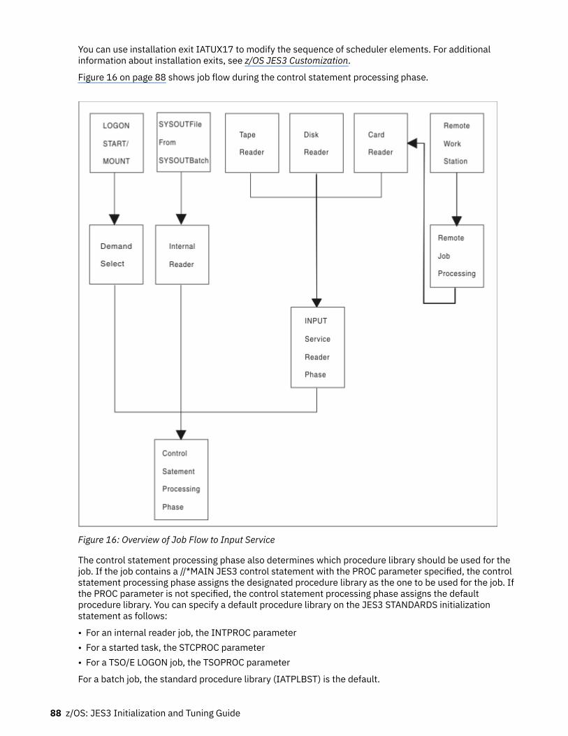
You can use installation exit IATUX17 to modify the sequence of scheduler elements. For additionalinformation about installation exits, see z/OS JES3 Customization.
Figure 16 on page 88 shows job flow during the control statement processing phase.
Figure 16: Overview of Job Flow to Input Service
The control statement processing phase also determines which procedure library should be used for thejob. If the job contains a //*MAIN JES3 control statement with the PROC parameter specified, the controlstatement processing phase assigns the designated procedure library as the one to be used for the job. Ifthe PROC parameter is not specified, the control statement processing phase assigns the defaultprocedure library. You can specify a default procedure library on the JES3 STANDARDS initializationstatement as follows:
• For an internal reader job, the INTPROC parameter• For a started task, the STCPROC parameter• For a TSO/E LOGON job, the TSOPROC parameter
For a batch job, the standard procedure library (IATPLBST) is the default.
88 z/OS: JES3 Initialization and Tuning Guide

If the PROC parameter specifies an invalid procedure id (procid), the job is flushed from the system. If thejob does not use any procedures (even if the PROC parameter is specified), JES3 does not assign a defaultprocedure library to the job.
Selecting a main for job execution
Sometimes a user may want to select the main on which to execute a particular job. For example, the jobcould need a feature or require an I/O device that is unavailable to some mains or not defined to JES3. Tobe sure the job executes on the right main, the user can do one of the following:
• Code either the SYSTEM or SYSAFF parameter on the JOB control statement or the SYSTEM parameteron the job's //*MAIN control statement.
• Assign the job to a job class that is enabled on only the required main.• Specify a scheduling environment by coding the SCHENV parameter on the job's JOB statement. This
requires your installation to define the scheduling environment in the WLM policy (see z/OS MVSPlanning: Workload Management for information about how to define resources and schedulingenvironments.).
If the user has specified a main by coding the SYSTEM or SYSAFF parameter on the MVS JOB statement orby coding the SYSTEM parameter on the //*MAIN control statement, the control statement processingphase assigns the job to execute on the specified main. Otherwise, the control statement processingphase assigns the job to execute on a main eligible for the job's job class. The SYSTEM= keyword on theJES3 CLASS initialization statement defines the eligible main(s) for a job class.
If no eligible mains are available, the job completes input service processing, then waits until an eligiblemain becomes available before starting C/I processing.
If the user specified a scheduling environment, then the status of the scheduling environment will beused in addition to the systems from the JOB statement, the //*MAIN control statement or JES3 CLASSinitialization statement to determine where a job will execute.
For example, suppose you have three systems in your SYSPLEX: SY1, SY2, and SY3. Suppose that a jobspecifies a scheduling environment, IMSPROD, which is available on SY2 and SY3. The following tableshows where the job will execute depending on what was specified on the the MVS JOB, //*MAIN JECL , orCLASS initialization statements:
Table 20: Where a job will execute based on //*MAIN JECL, JOB JCL and CLASS statements
JOB, //*MAIN or CLASS Statement Information Can Job Execute? On what system?
Nothing Specified YES — SY2 and SY3
// JOB SYSTEM=SY2 or //*MAIN SYSTEM=SY2 YES — SY2
// JOB SYSTEM=SY1 or //*MAIN SYSTEM=SY1 NO
// JOB SYSTEM=(SY1,SY3) or //*MAINSYSTEM=(SY1,SY3)
YES — SY3
CLASS, ...SYSTEM=SY2 YES — SY2
CLASS,...SYSTEM=SY1 NO
CLASS,...SYSTEM=(SY1,SY3) YES — SY3
CLASS,...SYSTEM=ANY YES — SY2 and SY3
Modifying JCL and JES3 Control Statements
After JES3 reads the input stream but before JES3 or MVS uses the information specified in the inputstream, JES3 installation exits can verify, modify, add, or delete information on:
• JOB, EXEC, DD, or OUTPUT JCL statements (except DD * or DD DATA statements)• JES3 control statements (statements that begin with //*) except //*DATA SET or //*ENDDATASET
JES3 job management 89

• JES3 control statements (statements that begin with /*) as allowed by specifying the ALTJCL=ACCEPTkeyword value on the STANDARDS initialization statement.
JES3 control statements begin with "//*". By default, JES3 also accepts JES3 control statements thatbegin with "/*". If you want to require that both slashes be used, specify ALTJCL=ERROR,ALTJCL=IGNOREW, or ALTJCL=COMMENT on the STANDARDS initialization statement, depending onwhether you want messages issued and whether you want a job containing such statements to beflushed. See z/OS JES3 Initialization and Tuning Reference for how to specify ALTJCL= on theSTANDARDS initialization statement.
To verify or change the JOB JCL statement, implement installation exit IATUX28. You can also use thisexit to remove the job from the system.
To verify or change the EXEC JCL statement or JES3 control statements, implement installation exitIATUX33. This installation exit also allows you to request that JES3 ignore the statement.
To verify or change DD JCL statements, use installation exit IATUX34. This installation exit also allows youto request that JES3 ignore the statement.
To verify or change an OUTPUT JCL statement or any JCL statements besides those listed above,implement installation exit IATUX44. This installation exit also allows you to request that JES3 ignore thestatement.
Preventing a Job from Dominating JSAM Buffers
To prevent a job with many JCL SYSIN DD statements from dominating JSAM buffers, use the job SYSINDD statement limit. If a job contains more SYSIN DD statements than the job SYSIN DD statement limitallows, JES3 cancels the job.
To select the job SYSIN DD statement limit, determine the number of SYSIN DD statements that are in thelargest job you want to run at your installation.
Note: 12 SYSIN DD statements will fit in a 4K JSAM buffer.
Specify the number of SYSIN DD statements on the MAXINDD= parameter of the STANDARDSinitialization statement. The next time you do a hot start with refresh, warm start, or cold start using theinitialization stream containing that STANDARDS statement, JES3 uses the job SYSIN DD statement limityou specified.
Converter/Interpreter ServiceConverter/Interpreter (C/I) service controls the conversion of JCL statements to Converter/Interpretertext and then into control blocks. This service comprises primarily the JES3 CI and POSTSCAN dynamicsupport programs, the C/I subtasks under which the MVS C/I routines run, and the initiator supportroutines.
C/I service controls the conversion and interpretation of a job's JCL. The three principal phases of C/Iservice are:
• Converter/Interpreter phase: Uses the MVS C/I routines to convert and interpret JCL into schedulercontrol blocks. At this time, the scheduler control blocks are created in the scheduler work area (SWA).
• Prescan phase: Extracts job requirements from the scheduler control blocks for use in the postscanphase. At the end of the prescan phase, the scheduler control blocks are moved from the SWA to JES3spool.
• Postscan phase: Locates data sets and gathers information for use in JES3 device setup.
You can define one or more C/I functional subsystem (FSS) address spaces to perform the converter/interpreter, prescan, and locate (catalog search) portion of the postscan phase for some or all jobs. A C/IFSS can operate on the global or any local main.
90 z/OS: JES3 Initialization and Tuning Guide

When a job enters the MAIN scheduler element, the JES3 initiator support routines move the schedulercontrol blocks from spool to the SWA in the user's address space. You can modify the scheduler controlblocks before they are moved to the SWA by implementing installation exit routine IATUX26.
For detailed information about how you can set up and influence C/I service, see Chapter 5, “Defining andmanaging C/I service,” on page 141.
Converter/Interpreter PhaseThe primary function of the converter/interpreter phase is to convert the JCL into Converter/Interpretertext, then interpret the Converter/Interpreter text and create scheduler control blocks.
When JES3 has a job that can be scheduled for C/I processing, it determines whether a CI DSP in theJES3 global address space or a C/I FSS address space is available for the job. You can select the mainwhere the job will be scheduled for C/I service as well as whether the job is eligible for C/I processing inthe JES3 global address space by implementing installation exit IATUX46. If the initialization streamdefines C/I FSS address spaces, you can override JES3's selection of an address space by implementinginstallation exit IATUX49. JES3 schedules the job to an available CI DSP based on the installation exitroutines' responses.
If the number of JCL statements in a job exceeds the job JCL statement limit, the JES3 calls installationexit routine IATUX41 to see if it should cancel the job. If so, JES3 cancels the job from the system withprint. (Operator messages refer to this type of cancellation as the job being “express canceled”.) If the jobis not to be canceled and there are no JCL errors, JES3 links to the MVS interpreter to create thescheduler control blocks from the Converter/Interpreter text.
At the end of interpretation, the Storage Management Subsystem (SMS) scans the SWA control blocks todetermine the required catalogs for new data sets. Catalogs for jobs can be SMS-managed or JES3-managed. SMS uses the list of SMS-managed volumes to determine which mains are eligible for catalogsearches. A list of catalogs that are not SMS-managed is returned to JES3 and becomes part of JES3'ssetup requirements.
When the C/I subtask finishes its work, the job enters the prescan phase of C/I service.
Prescan PhaseThe primary function of the prescan phase is to extract each job's resource requirements from the SWAcontrol blocks created in the interpreter phase.
On entry to the prescan phase, JES3 examines the SETUP parameter on the JES3 STANDARDSinitialization statement:
• If you specify SETUP=NONE (that is, you do not want JES3 to perform pre-execution setup for thecomplex), JES3 does not build extract resource requirements.
• If you specify any value other that NONE on the SETUP= keyword, JES3 determines the job's resourcerequirements.
Installation exits IATUX04, IATUX05, and IATUX06 allow you to examine or change job, step, and DDinformation, respectively. You can use these exits to examine or change the information before processingbegins.
During the prescan phase, the JCL for the job is examined for PGM=JCLTEST or PGM=JSTTEST. IfPGM=JCLTEST is found on an EXEC statement, the JCL is interpreted and the job is then express canceledon completion of the CI DSP. If PGM=JSTTEST is found on an EXEC statement, the job is processedthrough the prescan and postscan phases, a printed format of the job summary table (JST) is printed onthe JESYSMSG data set, and the job is then canceled-with-print on completion of the CI DSP. For moreinformation on JCLTEST and JSTTEST, see z/OS JES3 Diagnosis.
If the job is being processed in a C/I FSS, JES3 determines whether the job is eligible to have catalogsearches performed on the main where the C/I FSS is executing. If catalog searches can be performed on
JES3 job management 91

that main, locate processing occurs in the C/I FSS and control then returns to the JES3 global addressspace for the remainder of postscan processing.
Postscan PhaseThe functions of the postscan phase are to resolve cataloged data set references and prepare the job forthe main device scheduler (MDS).
Cataloged Data Set Resolution
If SMS is active, JES3 calls it to search the system catalogs and collect scheduling information for the job.SMS searches the system catalogs to obtain information about a job's data sets when the job's JCL doesnot specify unit information.
If SMS fails to find a data set name, the postscan phase calls installation exit IATUX07. Through thisinstallation exit, you can examine the available data set information and, if necessary, supply the unit andvolume information.
If a data set has been migrated (or is eligible to be migrated) by the Hierarchical Storage Manager (HSM),the LOCATE request for that data set causes JES3 to associate the data set with a set of volumes to whichit can be recalled. HSM limits the choice of volumes eligible for recall during LOCATE processing inaccordance with its space management algorithms. JES3 processing continues as though the data set isrecalled to all eligible volumes. However, the actual recall does not occur until job execution when MVSissues a LOCATE request. At that time, HSM determines which volume is the best choice to recall the dataset to and then recalls the data set to that volume. HSM derives an SMS storage class and an SMS storagegroup for SMS-managed data sets.
In addition, whenever the response of a LOCATE request has been received, you can use installation exitroutine IATUX11 to inhibit printing of the LOCATE request/response in the JESYSMSG data set.
C/I Service Preparation for the Main Device Scheduler
Although the JES3 main device scheduler performs volume fetching and setup, JES3 must determine thetype of setup used for each job. You specify the type of job setup by coding the SETUP parameter on theJES3 STANDARDS initialization statement or the end user can override your specification using the SETUPparameter on the //*MAIN statement in a job's JCL.
You can have installation exit IATUX08 examine the setup requirements for each job that uses job setup.When implemented, IATUX08 can modify the type of job setup or fail a job before the main devicescheduler receives control. See z/OS JES3 Customization for a complete description of installation exitIATUX08.
JES3 Resource AllocationJES3 provides a device management facility called the main device scheduler (MDS) that can wholly orpartially support the MVS allocation process. The purpose of MDS is to satisfy job resource requirements(the devices, volumes, and data sets needed) before and during job execution, thus allowing execution toproceed without allocation delays. MDS also allows controlled multisystem access to commonlyaccessible data sets in the loosely coupled environment.
You must choose whether to use the JES3 main device scheduler or use MVS (which controls the jobexecution) for the entire allocation process as each step begins execution. If you choose MDS, you mustthen decide whether utilization of MDS is to be partial (set up some jobs, some resources) or total (set upall jobs, all resources).
Note: You need to be aware that if MDS is used to provide resource management, MDS takes into accountthe availability of a job's scheduling environment during resource allocation. This scheduling environmentis a list of resource names and their required states that are used to help ensure that units of work aresent to systems that have the appropriate resources to handle them. Scheduling environments andresources are defined by the installation in the WLM policy (see z/OS MVS Programming: WorkloadManagement Services for more information).
92 z/OS: JES3 Initialization and Tuning Guide

MVS Allocation Compared with JES3 MDS AllocationMVS and MDS allocation consider a job's resource requirements at different levels. MVS allocationconsiders job requirements one step at a time for the processor executing the job; MDS considers theresource requirements for all the steps in a job for all processors in the loosely-coupled complex. Thesetwo approaches lead to the following differences between MDS and MVS allocation.
MVS Allocation
In systems that do not use MDS or the WLM functions of MVS, jobs are presented to MVS based on criteriasuch as job class, priority, or workload mix. In these systems, a job's requirements are not known until thejob entry subsystem selects the job for execution, and a system initiator begins the step allocationprocess. At each job step, MVS allocation attempts to satisfy the requirements for the step, in contentionwith every other job step currently executing on the same processor. If the requirements cannot be met,MVS allocation gives the operator the option of canceling the job or allowing it to wait for resources. Thus,in a system that does not use MDS, there may be jobs executing and other jobs waiting for resources.
The jobs waiting in MVS allocation hold critical resources (a system initiator, an address space, data sets,and possibly devices). Holding these resources longer than necessary makes it very difficult for thesystem programmer to determine how many initiators should be started to keep the system fully used,because at any given time, an unknown number of initiators may be waiting. MDS offers a solution to thisproblem.
Main Device Scheduler (MDS) Allocation
With MDS, the resources (data sets, devices, and volumes) that a job requires are already set up when thejob is passed to MVS for execution. There should never be an idle initiator caused by a job waiting forthese resources. Setup occurs while a job is in the JES3 address space, and the only system resourceused while the job is waiting is the JES3 queueing space. MDS helps the system make maximum use ofdevices and allows jobs to run in a minimum amount of time when they are passed to the system forexecution. Also, MDS cooperates with the workload management (WLM) component of MVS to ensurethat the scheduling environments for jobs are honored.
The main device scheduler requests and verifies the mounting of the initial volumes a job requires on eachdevice before the job can be selected for execution (unless deferred volume mounting is specified in theJCL).
After JES3 converter/interpreter scans the JCL for required volumes and data sets and after it determinesthe volumes required (by accessing the system catalog), the volume fetch facility issues tape or diskvolume request messages. If the system programmer specifies ALLOCATE=MANUAL on the JES3SETPARAM initialization statement, JES3 puts the job into the volume-wait queue. The job stays in thequeue until the operator releases it.
JES3 can schedule, for each main, a combination of jobs that will execute without contention for both thesharable and nonsharable devices and data sets attached to that main. Because MDS considers thevolumes and data sets for a total job and for all systems in the complex, it has more information on theirutilization than does system allocation. Thus, MDS can determine the volume and data set utilization forthe combination of jobs running at one time on any main.
The JES3 default method of reserving devices on a total job basis (Job Setup) may cause more devices tobe used by a job than would be required under MVS allocation. For example, because devices are initiallyset up on a job basis, a device used in a later job step may be reserved (but not used) during all the priorjob steps. MVS allocation avoids this problem by allocating at the job step level, and thus minimizing thenumber of devices used by a job.
Because setup occurs before job execution, JES3 cannot react to processing dependencies that can occurbetween different jobs and between different steps in the same job. This limitation is particularlyimportant when considering the cataloging and passing of data sets. JES3 cannot determine whether anyconditional job steps are skipped as a result of condition code processing. JES3 assumes that all jobsteps will execute. JES3 also counts the number of I/O devices needed by each step. Anotherconsequence of this limitation is that if the VOLUME=(,RETAIN) parameter is specified in the JCL, allretained volumes are treated as public, even though PRIVATE may have been explicitly specified on the
JES3 job management 93

DD statement. Therefore, a private volume may end up being unloaded at the end of a step even thoughRETAIN was specified. In such cases, the MVS RETAIN message is issued.
The JES3 main device scheduler controls the volume fetching, allocation, mounting, and deallocation ofI/O devices associated with job execution on all processors in a loosely-coupled complex.
If a job is assigned a scheduling environment (for example, the SCHENV= parameter was specified on theJOB statement), the availability of the job's scheduling environment is taken into consideration whendetermining which systems have the resources for a job. If a job's scheduling environment is not availableon a particular system, the job will not run on that system even if the other resources required by the job(e.g. DASD volumes, SMS storage groups) are available on that system. If the scheduling environmentlater becomes available on a system, the job will be able to run on that system provided that theresources required by the job are also available on that system.
MDS is divided into the following stages:
• Volume fetch• System select• Allocation• Volume verification• System verify• Breakdown
Volume Fetch
Volume fetch, the first phase of MDS, is performed for all jobs entering MDS. This phase determines thevolumes required by the job and, if necessary, instructs the operator to get the volumes from the library.This phase also eliminates those mains on which the job cannot run.
During fetch processing, JES3 builds volume entries and issues messages for volumes that have noentries in the SETVOL table which contains the volume serial number for each reference to a devicemanaged by MDS.
Volume fetch messages are selected optionally by specifying FETCH=YES on the JES3 SETPARAMinitialization statement. When you select the fetch option, JES3 issues volume fetch messages to indicatewhich volumes are required for specific jobs to execute. JES3 sends fetch messages to the consolespecified by the TAFETCH (for tape volumes) and DAFETCH (for direct-access volumes) parameters on theSETPARAM initialization statement. Volumes already mounted require no fetch processing, and volumesthat have been fetched but not mounted get action-coded messages. Device types other than tape or diskdo not require operator action. If you do not specify the volume fetch option, jobs go directly into thesystem select stage of MDS if the job requires SMS-managed resources, or into allocation if the job doesnot require SMS-managed resources.
System Select
The system select phase of MDS is performed when a job requires one or more resources managed by thestorage management subsystem (SMS). If the job does not require any SMS-managed resources, the jobproceeds directly to MDS allocation.
JES3 is not aware of the availability or connectivity of SMS-managed resources. If a job requires SMS-managed resources, JES3 requests SMS to determine the availability of those resources and to determinewhich mains have access to those resources.
If a required SMS-managed resource is temporarily unavailable, the job waits in system select until theresource becomes available. You can use an *INQUIRY,S,SS,J= command to determine why jobs arewaiting. If all required SMS-managed resources are available, SMS provides JES3 with a list of mains thathave access to those resources. JES3 uses the list of eligible mains passed by SMS to determine whichmains have access to all of the required resources for the job (both SMS-managed and MDS-managed.)
If JES3 determines that one or more mains have access to all of the required resources, the job proceedsinto the allocation phase. If no mains have access to all of the required resources, JES3 invokes user exitIATUX61 to determine whether the job should be placed on the MDS error queue or canceled. If you do
94 z/OS: JES3 Initialization and Tuning Guide

not implement IATUX61, MDS places the job on the MDS error queue where an operator must eitherrestart the job or cancel it using a *RESTART,SETUP or *CANCEL,SETUP command respectively. See z/OSJES3 Commands for information about how to restart or cancel jobs in setup. See z/OS JES3Customization for information about using IATUX61.
Allocation
This phase of MDS uses allocation algorithms to provide required devices. When allocation is successful,JES3 issues mount request messages for all required volumes except:
• Deferred mount requests - where no mount is as yet requested but the device that the volume is to bemounted on is allocated to the user.
• Permanently resident volumes - where the mount is unnecessary• Multi-volume mount - where only the first volume of a multi-volume data set is mounted; secondary
volumes are not mounted until required.
You can use the ALLOCATE= keyword on the JES3 SETPARAM initialization statement to control how youwant jobs processed during MDS allocation. If you specify ALLOCATE=AUTO (default), MDS sendsincoming jobs directly into allocation unless a job requires SMS-managed resources. If a job requiresSMS-managed resources, the job is first sent to system select before proceeding into the allocationphase.
If you specify ALLOCATE=MANUAL, the operator must issue the *START,SETUP command for each jobrequiring volumes to be fetched before the job can go through MDS allocation. Jobs that require volumesto be fetched are kept in the MDS WAITVOL queue; the contents of this queue can be obtained by issuingthe *INQUIRY,S,W, command. Setup is performed for dynamic allocation requests at the time eachrequest is made.
To start the allocation phase of MDS, a job is selected from the ALLOCATE queue. MDS examines the job'sresource requirements and attempts to allocate the required devices, volumes, and data sets. If a jobrequires SMS-managed resources, only the data set(s) is allocated. JES3 is not aware of SMS-managedvolumes and devices. When MDS initially tries to set up a job, it records the total device, volume, and dataset requirements for the job. When allocation fails because needed devices, volumes, or data sets areunavailable, the job is queued for another attempt. However, MDS sends jobs back to the system selectphase of MDS if all of the following conditions occur:
1. A job requires both SMS-managed resources and MDS-managed resources.2. The list of eligible mains determined by the system select phase do not have access to both the MDS-
managed resources and the SMS-managed resources.3. One or more mains not in the original list of mains has access to all of the required resources, and the
SMS-managed resources are temporarily unavailable to those mains.
In the latter case, the job is sent back to system select and waits until the required SMS-managedresources become available on a main that also has access to the required MDS-managed resources.
Device selection (through initialization parameters) limits the number of mains that can execute a jobwhenever a needed I/O device is not shared among all eligible mains. Any main that cannot allocate arequested device or satisfy the total resource requirement is ineligible to run the job.
A job that requests use of a volume that the operator has designated as “unavailable” (through the*F,S,VU= command) is placed on the volume unavailable queue if the job has not already completed theallocation process. A job that allocated a volume before that volume being made unavailable is allowed tocomplete normally.
Volume Verification
JES3 issues messages that instruct you to mount a job's required volumes. You can implementinstallation exit IATUX62 to validate, accept, or override JES3's decision about whether a volume hasbeen successfully mounted. JES3 invokes IATUX62 after the volume verification phase of MDS.
The VERIFY function automatically obtains the volume serial number, label status, and other informationfor MDS after you mount the job's required volumes. You can install installation exit IATUX25 to validate
JES3 job management 95

any nonstandard labels used in the installation. When all volumes are properly mounted, the job is readyfor execution. However, if the job requires SMS-managed resources, it proceeds to the system verifyphase of MDS before execution. Device types other than tape or disk do not require operator action.
For more information about installation exits IATUX25 and IATUX62, see z/OS JES3 Customization.
System Verify
The system verify phase of MDS is performed when a job requires SMS-managed resources. This phase ofMDS ensures that all of the SMS-managed resources required by a job are still available before execution.For example, if a job spends too much time in MDS allocation or a long period of time elapses between amount request and the actual mounting of a required volume, one or more of the SMS-managed resourcescould become unavailable.
If the status of SMS-managed resources required by the job has not changed, that is, all of the requiredSMS-managed resources are still available and are accessible by the eligible main(s), the job can proceedinto execution.
However, if SMS-managed resources required by a job are no longer available, JES3 generates a new listof systems where SMS managed resources are available. JES3 then checks this list against the following:
• All jobs to see if they can access the SMS and JES3 resources• Batch jobs to see if the class and group are available on the systems where SMS managed resources are
available.• Batch jobs with associated scheduling environments to see if there are any systems where the
scheduling environment and the SMS managed resources are available.
If there are no systems where all of the above resources are available, the job is sent to the breakdownphase where MDS deallocates resources held by the job. MDS then sends the job back to the systemselect phase where MDS retries allocation.
Breakdown
JES3 automatically performs the breakdown phase of MDS when a job no longer needs a resource such asa data set, volume, or device. The resource is then available for use by other jobs. MDS does notdeallocate SMS-managed resources other than data sets because JES3 is not aware of SMS-manageddevices and volumes.
JES3 issues messages that indicate whether volumes should be retained for use by other jobs ordemounted. The RETAIN and KEEP messages issued by MVS allocation apply only to the resources usedwithin one job, while the RETAIN and KEEP messages issued by MDS consider volume usage by all jobscurrently in the system that use JES3-managed or jointly-managed devices. In the event that both MVSand JES3 issue KEEP or RETAIN messages regarding a specific volume, the JES3 messages take priority.
Jobs that have had errors during the FETCH, ALLOCATION, or VERIFY phases of MDS, or that have failedMDS restart processing are placed on the MDS error queue. You must restart or cancel these jobs usingJES3 commands. You can prevent operator intervention by coding installation exit IATUX61. IATUX61allows you to cancel jobs that would otherwise be placed on the MDS error queue. For more informationabout installation exit IATUX61, see z/OS JES3 Customization.
Types of SetupThe JES3 setup type is defined by JES3 initialization statement parameters and JCL control statements,and by JES3 operator commands. This section describes some of the parameters needed to define setupto the system.
JES3 performs three different types of setup based on the installation and user requirements:
• Job setup• High watermark setup• Explicit setup
96 z/OS: JES3 Initialization and Tuning Guide

The system programmer can use JES3 initialization parameters and JES3 control statements to controlallocation according to device types. For example, job setup can be used for disks, and high watermarksetup for tapes.
General considerations for each type are discussed below; setup examples are described in z/OS MVS JCLUser's Guide.
Job Setup
By using job setup you can cause JES3 to:
• Reserve all devices needed by a job before the job executes• Mount all volumes needed by the job before the job executes
Thus, after the job starts to execute, it does not have to wait between job steps to have a device allocatedor a volume mounted.
There are exceptions to the previous statements, however. The exceptions occur for:
• Deferred volume mounting• Dynamic allocation• The mounting of other than the first volume of a multivolume data set on the same device.
For a multivolume data set, if the unit count and the volume count are unequal (unit count and volumecount are DD statement subparameters), JES3 mounts the number of volumes specified as the unit count.Thereafter, MVS mounts subsequent volumes as they are needed.
When job setup is used, devices, volumes, and data sets are available for use by other jobs as soon as theDD statement is deallocated in the last step using the resource. Disadvantages of job setup are inefficientdevice usage and reserving devices for a job during steps when they are not used.
Job setup is used when SETUP=JOB is specified on a //*MAIN control statement for the job. If the SETUPparameter is not specified on the //*MAIN statement, then job setup is used only when specified (orassumed by default) on the STANDARDS initialization statement.
High Watermark Setup
High watermark setup, as defined on the HWSNAME initialization statement, reduces the number ofdevices JES3 reserves for a job. To determine how many devices of a particular type to reserve for a job,JES3 considers the needs of each of the job's steps. In this way, JES3 determines which step needs thegreatest number of devices of that type; JES3 then reserves that many devices of that type for the job.JES3 repeats this process for each device type the job needs. As a result, high watermark setup can causepremounting of all mountable volumes. Volume unloading and remounting may occur for both private andpublic volumes, even when RETAIN has been specified on the applicable DD statement.
When high watermark setup is used, as in job setup, devices, volumes, and data sets are returned to JES3for use by other jobs as soon as the DD statement is deallocated in the last step using the resources.When it is advantageous to use fewer devices for a job, high watermark setup is preferable to job setup.
High watermark setup is used when SETUP=THWS (for tapes only), SETUP=DHWS (for disks only), orSETUP=HWS (for tapes, disks, graphics, and unit-record devices). If the SETUP parameter is not specifiedon a //*MAIN statement, then high watermark setup is used only when SETUP=THWS, SETUP=DHWS, orSETUP=HWS is specified on the STANDARDS initialization statement or when the specified setup isoverridden by installation exit IATUX08.
Cataloged data sets may reference devices that are valid for use during HWS. You define these devicesusing the HWSNAME initialization statement. If a cataloged data set references a device that has beenremoved as a HWS device (that is, the device has been removed from the HWSNAME initializationstatement), that data set is no longer eligible for HWS processing.
JES3 job management 97

Explicit Setup
This setup provides a means for the application or system programmer to combine the executionadvantages of job setup and the device usage advantages of high watermark setup. To specify explicitsetup, use the SETUP parameter on the //*MAIN JES3 control statement.
When explicit setup is specified, the job's devices are allocated using job setup. Only the device premountcharacteristic is affected by specifying explicit setup. Explicit setup is mutually exclusive with any highwatermark setup. The device allocation for job setup is the default when explicit setup is specified.
An advantage of explicit setup over high watermark setup is that volumes can be forced to remainmounted on devices until they are no longer needed. Job setup and high watermark can deallocateresources (device, volumes, and data sets) at the end of any step if the resources are no longer needed.
Explicit setup is used when the SETUP=(ddname[,ddname]...) parameter is specified on a //*MAINstatement for the job. To explicitly specify data sets that are not to be set up, the SETUP=/(ddname[,ddname]...) parameter should be specified.
Initializing MDSThe operation of MDS is affected by the parameters chosen for the following JES3 initializationstatements: CLASS, DEVICE, GROUP, SELECT, SETACC, SETNAME, SETPARAM, SETRES, and STANDARDS.
CLASS Initialization Statement
The SDEPTH parameter on the CLASS statement limits the number of jobs of a specific class (requiringmountable devices) that can be active in setup at the same time. Thus a class restricted to a smallnumber of devices (such as a test class) can be prevented from monopolizing mountable devices.
DEVICE Initialization Statement
The XUNIT parameter of the DEVICE statement specifies the routing information for all JES3 and MVSdevice-related messages. The XUNIT parameter accepts an MVS routing code or a JES3 destination classfor messages that pertain to the device being defined. If you want a particular RJP console to receivemessages for this device, the message destination must be assigned to the RJP console through theDEST= parameter of the CONSOLE statement. For efficiency, the console should be near the device. Usethe ROUTCODE parameter on the CONSOLE statement in the CONSOLxx parmlib member to assignmessage destinations to MCS consoles.
As an example, suppose the following direct access and tape devices are defined:
DEVICE,XTYPE=(3390,DA),XUNIT=(130,SY1,S5,ON) . . .DEVICE,XTYPE=(3390,DA),XUNIT=(137,SY1,S5,ON)DEVICE,XTYPE=(3390,DA),XUNIT=(230,SY1,S6,ON) . . .DEVICE,XTYPE=(3390,DA),XUNIT=(237,SY1,S6,ON)DEVICE,XTYPE=3490,XUNIT=(180,SY1,S7,ON)
In order for RJP work station T0001 to receive messages associated with these devices, the followingCONSOLE statement would have to be specified:
CONSOLE,TYPE=RJP,JNAME=T0001,DEST=(S5,S6,S7)
The XTYPE parameter allows the specification of device class and volume removability. Thesesubparameters, normally defaulted to tape (TA) and removable (RM), can be used to indicate a JES3-managed device that contains a permanently resident volume. For example:
DEVICE,XTYPE=(3390,DA,PR),XUNIT=(230,SY2,S5,ON)
98 z/OS: JES3 Initialization and Tuning Guide

would establish the volume on local processor SY2 unit 230 as permanently resident.
If a device has multiple access, it should be specified in the XUNIT parameter of the DEVICE statementfor all processors. For example:
DEVICE,XTYPE=(3390,DA,PR),XUNIT=(230,SY1,S1,,132,SY2,S2)
You can also specify that a device is defined to all processors by using the processor name *ALL. Forexample:
DEVICE,XTYPE=(3390,DA,PR),XUNIT=(230,*ALL,S1)
When using *ALL, the same device number, message destination, and initial online/offline status apply toevery processor. You can define a range of devices with a single device statement by using the NUMDEVkeyword. For example:
DEVICE,XTYPE=(3390,DA,PR),XUNIT=(230,*ALL,S1),NUMDEV=5
indicates that devices 230, 231, 232, 233, and 234 are defined on all processors.
GROUP Initialization Statement
Device pooling for job-class groups is controlled by the specification of either the DEVPOOL parameter orthe device dedication positional subparameters in the EXRESC parameter. The basic difference betweenthe two methods of dedication is that devices dedicated through the EXRESC parameter are dedicatedwhen the group is allocated on the processor specified in the EXRESC parameter, while DEVPOOL-requested dedication is accomplished when the group is enabled on any processor. The allocation optionsof ANY or GROUP are used to determine whether a job that is not able to obtain all its required devices forvolume mounting is allowed to go beyond the dedicated devices to satisfy its requirements. Normally, agroup representing higher priority work would be allowed to go beyond the dedicated devices (ANY) iffewer than the total number required were dedicated. A group representing testing might be assigneddedicated devices to limit its impact on the throughput of production work by only allowing it to allocatededicated devices (GROUP).
SELECT Initialization Statement
Several parameters on the SELECT statement affect the operation of MDS allocation on a processor basis(SDEPTH, SBAR, INCR, INCL, SAGER, SAGEL). Through these parameters, MDS allocation may be biasedtoward one processor (a larger SDEPTH), devices may be reserved but not entirely allocated to oneprocessor (a higher SBAR), and jobs on a specific processor may be favored for selection (higher INCR,INCL, SAGER, and SAGEL parameters).
SETACC Initialization Statement
The SETACC statement is used to describe volumes that are found on permanently resident devices nottotally shared by all processors in the complex. If the processor from which these volumes can beaccessed has not been initialized, jobs requiring these volumes wait rather than request them to bemounted elsewhere. When a processor is initialized, the volumes found supersede those (if different)specified in the SETACC statement.
SETNAME Initialization Statement
The JES3 MDS algorithm uses the information specified on the SETNAME statement when searching forthe proper device to be allocated for a DD request.
If a DD request is to be handled by JES3, the value (excluding the specific device number) specified in theUNIT parameter of the DD statement must also be specified in the NAMES parameter of the SETNAMEstatement. If the request specifies a device number in the UNIT parameter, the device number must alsobe specified in the XUNIT parameter of the DEVICE statement.
By specifying the same names in a different order for the same XTYPE, it is possible to create a preferenceorder of device selection for requests requiring volume mounting. This preference might be to achievechannel path separation, if possible, while still allowing this job to run if separation cannot be achieved.
JES3 job management 99

Devices with Three Channel Paths
DEVICE,XTYPE=(3330CH1,DA),XUNIT=(130,SY2,S1,ON) DEVICE,XTYPE=(3330CH2,DA),XUNIT=(230,SY2,S1,ON) DEVICE,XTYPE=(3330CH3,DA),XUNIT=(330,SY2,S1,ON) SETNAME,XTYPE=3330CH1,NAMES=(DACH1,DISK1) SETNAME,XTYPE=3330CH2,NAMES=(DACH1,DACH2,DISK2) SETNAME,XTYPE=3330CH3,NAMES=(DACH1,DACH2,DACH3,DISK3) SETNAME,XTYPE=3330CH1,NAMES=(DACH2,DACH3) SETNAME,XTYPE=3330CH2,NAMES=(DACH3)
Requests for DACH1 would attempt allocation on channel path 1, then channel path 2, and finally onchannel path 3. Similarly, requests for DACH2 would attempt allocation first on channel path 2, thenchannel path 3, then channel path 1. By using DISK1, DISK2, or DISK3, strict channel path separationcould be achieved.
Although a name may appear in more than one SETNAME statement, all XTYPE parameters applying tothe name must be the same type (all DA for example). All names on the SETNAME statement must bedefined to MVS.
The maximum number of unique names specified on the SETNAME statement must not exceed 255. EachXTYPE should be defined to allow JES3 allocation to reference as large a collection of devices as possibleto minimize the number of name/unit references that need to be examined by the JES3 allocationalgorithm. The most frequently referenced names should be specified first (DASD, then tape, unit-record,and graphic devices).
The POOLNAMS parameter is provided to allow a convenient method of dedicating specific devices, eventhough there is no specific generic or esoteric name subset that exactly describes the attributes to beused to choose a specific set of devices. These names are allowed to be used only to dedicate devices andmay not be used in the DD statement UNIT parameter.
To allow the use of devices outside of MDS control, define MVS names to include the required devices andthen omit these names from the SETNAME initialization statement.
SETPARAM Initialization Statement
The ADDRSORT parameter can be used to dictate the order in which MDS looks for mountable devices inattempting allocation. If ADDRSORT=NO is coded, the SETUNIT tables are ordered in the same sequenceas the DEVICE statements in the initialization stream. This may be useful in cases when device locationsare not physically ordered by ascending device number.
SETRES Initialization Statement
The SETRES statement is used to describe volumes that are to be MDS-mounted when found onremovable direct-access devices during processor initialization. Any volume found may later be maderemovable by an MDS unload command (*MODIFY,S) issued by the operator.
STANDARDS Initialization Statement
The STANDARDS statement indicates the system standard for allocation of devices identified by theNAMES parameter on the SETNAME statement. The SETUP parameter on the STANDARDS statementspecifies the type of setup processing.
Operator Control of MDSThe operator may use several commands to control the JES3 MDS process. For detailed information onthe MDS commands, see z/OS JES3 Commands.
Job Selection and SchedulingEach time an MVS initiator requests work, generalized main scheduling (GMS) selects and schedules a jobfor execution. The job that GMS selects depends primarily upon initialization parameters that you havespecified.
100 z/OS: JES3 Initialization and Tuning Guide

Deadline scheduling and dependent job control (DJC), additional GMS functions, enable you to controlwhen jobs execute. With deadline scheduling, you specify a deadline by which you want the job to run.JES3 periodically increases the job's selection priority in an attempt to run the job by the specifieddeadline. DJC allows you to create a network of related jobs.
Comparison of JES3 and WLM initiator managementThe installation can have JES3 or Workload Manager (WLM) or both manage initiators for batch jobs. JES3or WLM control of initiators is at the job class group level. To specify whether JES3 or WLM managesinitiators for a job class group, the installation uses the MODE parameter on the GROUP initializationstatement. If MODE=JES is specified or defaulted, the initiators are managed by JES3. If MODE=WLM isspecified, the initiators are managed by WLM. The MODE parameter can also be changed dynamicallyusing the *MODIFY,G command. A group must be either WLM managed or JES3 managed; it cannot beWLM managed on one system and JES3 managed on another.
There are a number of reasons why you might choose WLM initiator management over JES3 initiatormanagement:
• Fewer and simpler externals exist.
Less externals are needed in JES3 to control WLM-managed initiators and to perform workloadbalancing. When the service administrator defines the performance goals and classification rules in theWLM policy, the system takes over the job of starting and stopping initiators.
• Externals reflect customer expectations.
With JES3 initiator management, it is the installation's responsibility to determine the number ofinitiators to be started on each system, the correct mix of jobs, and so forth. The externals do not reflectan actual performance goal, such as one hour turn around time for jobs in class X. How do you translateone hour turn around time into initialization statements?
With WLM initiator management, initiators are managed by WLM according to the service classes andperformance goals specified in the WLM policy. The performance goals are typically expressed in termsthat are found in service level agreements (for example, one hour turn around time).
• Dynamic, goal oriented initiator management exists.
The system adapts to changing conditions and how well the work is meeting its performance goals. Thecurrent JES3 initiator management puts the responsibility on the system programmer/operator tomanage the work. Workload balancing algorithms used by JES3 are difficult to define and static innature; they require an operator command and sometimes a JES3 hot start to change. But even if theycan be changed easily, why should human intervention be required? An operating system can betterperform these tasks.
• Workload balancing across a SYSPLEX is automatic.
WLM decides when to start initiators and how many to start based on performance goals and theimportance of batch work with respect to other work.
Note: WLM management of initiators does not necessarily imply that there will be an equal number ofinitiators on each system.
A comparison between JES3 and WLM initiator management results in the following.Initiator Control
JES3-managed initiators (how many, when to start them, and where to start them) are controlled byJES3 based on the EXRESC parameter of the GROUP initialization statement and through the use ofthe *MODIFY,G command.
WLM-managed initiators are controlled entirely by WLM. WLM determines how many initiators to start,when to start them, and where to start them based on performance goals in the WLM policy, backlogof jobs, and system capacity.
JES3 job management 101

Externals
JES3-managed initiators are expressed in terms of resources, not goals. For example, the EXRESCparameter on the GROUP initialization statement is used to specify how many initiators should bestarted, on what system, and when they should be started and stopped. The JOBMIX and CHOICEparameters on the SELECT initialization statement are used to specify the correct mix of jobs and thebest job to select based on the number of active initiators on a particular system.
WLM-managed initiators are expressed in terms of goals and their importance in the WLM policy. Forexample, batch work in class A should have one hour turn around time. Batch work in priority 0-2 hasa discretionary goal and should be run only when there is excess capacity.
System Performance
JES3-managed initiators are started and stopped based on installation definitions and the backlog ofjobs. How the system is performing, whether work is meeting its performance goals, or whether workis more important than other work is not considered. If you ask JES3 to start 100 initiators on aparticular system, it will do so without regard to whether it is the correct thing to do. As a result, whenjobs are selected to run, there is no guarantee that the jobs will actually make progress, because thejobs will be under SRM's control at that point and subject to the performance goals defined in theWLM policy.
WLM-managed initiators are started and stopped based on performance goals, available capacity,work importance, and information from JES3 about the backlog of jobs.
Association
JES3-managed initiators are associated with a job class group as defined in the GROUP initializationstatement. A job class group consists of one or more job classes defined in the CLASS initializationstatement. An initiator that is started for a particular job class group only selects jobs that belong tothat group.
WLM-managed initiators are associated with a service class. An initiator started for a service classonly selects work from that service class. A service class is a group of work that has the sameperformance characteristics, resource requirements, or importance. Service classes are defined in theWLM policy. Jobs are assigned a service using the classification rules in the WLM policy. See z/OS MVSPlanning: Workload Management for more information on defining service classes and classificationrules.
Note: Even through WLM management of initiators is at the job class group level, there is no one toone correspondence between job class groups and service classes (unless you define it that way inthe classification rules in the WLM policy). Therefore, for a particular job class group there can be jobswith different service classes, but all jobs in that group will run under either a JES3-managed or WLM-managed initiator.
Job Selection
For JES3-managed initiators, jobs are selected within a job class group by priority. If there is morethan one job with the same priority, the jobs are ordered by the time they are ready to be selected torun (that is, when they arrive on the GMS select queue). Changing a job's priority affects when the jobis selected to run.
For WLM-managed initiators, jobs are selected within a service class by their main service arrival time.Main service arrival time is the elapse time for C/I processing of a job. Job priority does not influencewhether a job is selected to run first; therefore changing the priority for a job has no effect unless sucha change causes the job's service class to change to one having more aggressive goals.
Because main service arrival time is used to order jobs waiting for a WLM-managed initiator, a job in aWLM-managed group that requires setup can actually be selected to run before that it would if its wasin a JES3-managed group. For example, suppose the following situation exists:
Table 21 on page 103 illustrates how JES-managed and WLM-managed jobs are selected.
102 z/OS: JES3 Initialization and Tuning Guide

• Two jobs (JESTAPE and WLMTAPE) waiting in MDS processing for their tapes to be mounted. One job(JESTAPE) is in a JES-managed job class group and the other (WLMTAPE) is in a WLM-managed jobclass group.
• Assume that there are four jobs waiting to be selected to run in both the JES-managed and WLM-managed job class groups.
• Assume that two of the jobs in each group completed C/I processing after the jobs that require thetape mounts. That is, their main service arrival times are after the jobs that require the tape mounts.
• Assume that all jobs in both groups have the same priority and take the same amount of time to run.
Explanation
If the tape mounts are satisfied for both jobs at the same time, the job in the WLM-managed groupwill be selected to run first, because jobs in the JES-managed groups are ordered by priority andthe job (JESTAPE) in the JES-managed group will be added to the end of the queue. Jobs in theWLM-managed groups are ordered by main service arrival time; therefore, the WLM-managed job(WLMTAPE) will be added to the middle of the queue; the amount of time the job actually holdsthe resource will be shorter compared to the JES-managed jobs, because it takes longer for theJES-managed job to be selected to run.
Table 21: Overview - Job Selection.
GMS Select (before allocation complete) MDS Allocation
JES JESJOB1(Time=4)
JESJOB2(Time=2)
JESJOB3(Time=1)
JESJOB4(Time=5)
JESTAPE(Time=5)
WLMTAPE(Time=3)
WLM WLMJOB3(Time=1)
WLMJOB2(Time=2)
WLMJOB1(Time=4)
WLMJOB4(Time=5)
GMS Select (after allocation complete)
JES JESJOB1(Time=4)
JESJOB2(Time=2)
JESJOB3(Time=1)
JESJOB4(Time=5)
JESTAPE(Time=3)
WLM WLMJOB3(Time=1)
WLMJOB2(Time=2)
WLMTAPE(Time=3)
WLMJOB1(Time=4)
WLMJOB4(Time=5)
Workload Balancing
For JES3-managed initiators, some workload balancing exists but it is difficult to define and static innature. JES3-managed initiators do not adapt to changing workloads and system conditions. There isnot direct correlation between the externals and the performance goals that are required.
The following initialization parameters can be used to perform workload balancing for JES3-managedinitiators:
• JOBMIX on the SELECT initialization statement• CHOICE on the SELECT initialization statement• LSTOR on the SELECT initialization statement• IORATE on the CLASS initialization statement• LSTRR on the CLASS initialization statement
For WLM-managed initiators, JES3's workload balancing externals are ignored. WLM automaticallymakes adjustments based on performance goals, importance, and available capacity.
Class Limits
Class limits can be used for both JES3-managed and WLM-managed initiators to control the numberof jobs in execution. Class limits are specified on the CLASS initialization statement and can be one ofthe following:
JES3 job management 103

• TDEPTH to limit the number of jobs in this class that can run in the entire SYSPLEX (JESPLEX).• MDEPTH to limit the number of jobs in this class that can run on a particular system.• MLIMIT to limit the number of jobs in this class that can run on a particular system based on the
number of jobs running on that system in another class.
Priority aging is performed for jobs in JES-managed job class groups. Aging causes a job's priority tobe increased when an unsuccessful attempt is made to allocate the job's resource requirements or toselect the job. The installation specifies priority aging using the SAGER/SAGEL and MAGER/MAGELparameters on the SELECT initialization statement. SAGER and SAGEL are used for jobs waiting tohave their resource allocated. MAGER and MAGER are used for jobs waiting to be selected forexecution.
For WLM-managed job class groups, job selection related priority aging is not performed. Jobs inWLM-managed job class groups are queued for selection by their main service arrival time and nottheir priority. Priority, by itself, is not sufficient for job selection because it is only one of the manycriteria used to classify a job. If priority is important to your installation, then it should be reflected inthe WLM classification rules and the service classes assigned to jobs.
For WLM-managed job class groups, setup-related priority aging (SAGER and SAGEL) is still performedbecause jobs are setup and queued by priority; priority is still a factor in allocating a job's resources.
Queue Delay
If a velocity goal is defined for a service class that is used for batch jobs, queue delay (i.e. the amountof time the job spends waiting for an initiator) is not included in the velocity calculation for JES3-managed initiators.
For WLM-managed initiators, queue delay is included in the velocity calculations. If a service classwith a velocity goal is not meeting its goals, and queue delay is a significant reason for not meeting thegoal, WLM can start more initiators for the service class. See z/OS MVS Planning: WorkloadManagement for more information on velocity goals.
Resource Use
JES3-managed initiators are started by JES3 and take up JES3 job numbers and spool space.
WLM-managed initiators are started by WLM and do not take up JES3 job numbers and spool space.
Modes of Operation
For JES3-managed initiators, WLM can run in either compatibility mode or goal mode.
For WLM-managed initiators, only goal mode is allowed on the JES3 global and any JES3 local systemwhere you want WLM-managed initiators to be started. If any JES3 local is in WLM compatibilitymode, then WLM-managed initiators cannot be started on that system.
When you activate WLM initiator management, JES3 does not check to see if WLM is in goal mode ornot. Also, JES3 inquiry commands do not show that WLM is in compatibility mode. Your only indicationof WLM running in compatibility mode will be that no initiators will be started on the systems that arein compatibility mode.
Release Levels
JES3 can be at any level to run JES3-managed initiators.
JES3 must be at least at the OS/390® Version 2 Release 8 level on the global and any local where youwant WLM-managed initiators started. If a particular local is not at the JES3 OS/390 Version 2Release 8 level, WLM-managed initiators cannot be started on that system.
Classifying JobsWLM classification is responsible for assigning a service class and optionally a report class to a job basedon the classification rules in the WLM policy. A service class is a group of work which has the sameperformance goals, resource requirements, or business importance. For workload management, you
104 z/OS: JES3 Initialization and Tuning Guide

assign a service goal and optionally a resource group to a service class. WLM starts initiators on a serviceclass basis.
A report class is a group of work for which reporting information is collected separately. For example, youcan have a report class for information combining two different service classes, or a report class forinformation on a single transaction. A report class is not used by WLM initiator management.
Before OS/390 JES3 Version 2 Release 8, jobs were classified during execution. With OS/390 JES3Version 2 Release 8, jobs are classified at the end of C/I processing after user exit IATUX09 has beencalled. Classification is performed for all batch jobs, not just for jobs in WLM-managed groups.
When a job is classified, the following information is provided to you so that you can classify jobs:
• Job name (called transaction name in the classification rules)• Job class (called transaction class in the classification rules)• PERFORM parameter from the JOB statement. (The PERFORM parameter on the EXEC statement is not
used and cannot be used to assign a new service class when a new step begins to execute.)• Owner (RACF user id)• Priority• Accounting information• Subsystem type - JES• Subsystem name - JES3 subsystem name (typically "JES3")
See z/OS MVS Planning: Workload Management for more information on how to setup classification rulesand service classes.
After a job is classified, it may be reclassified:
• When a job's priority is changed as a result of a *MODIFY,J=job,P=xx command or because of deadlinescheduling. Because a job's priority is one of the inputs to classification, the job's service class maychange when the priority is changed.
• When a job's class is changed with a *MODIFY,J=job,CLASS=class command. Because a job's class isone of the inputs to classification, the job's service class may change when the class is changed.
• When a new WLM service definition is installed and activated. The classification rules can be changedand service classes can be added or deleted only by installing and activating a new WLM servicedefinition. When this occurs, jobs are reclassified to pick up the latest changes to the WLM servicedefinition.
A job is not reclassified when its priority is changed through the use of the SAGER or MAGER parameterson the SELECT initialization statement. Unlike deadline scheduling, priority aging only updates a job'spriority temporarily for the purposes of moving the job up in the queue ahead of other jobs. When a jobhas completed setup or has been selected to run, the priority is restored to its original value.
Pre-execution delaysWhen a job enters the system, there are a number of circumstances that can affect when a job is selectedto run. For example, the job could be placed into operator hold, the job's resources may not be available,the job's class and group may not be enabled, or all initiators may be in use.
For jobs in WLM-managed groups, WLM has control over only the amount of time a job waits for aninitiator (which is known as queue delay). If a service class is not meeting its goals and queue delay is asignificant part of why the goals are not being met, WLM can help the service class by adding moreinitiators. WLM cannot control how long a job is in operator hold, how long it takes to allocate resources,and so forth. These forms of delay are included in WLM's calculations by JES3. JES3 is responsible forkeeping track of the types of delays and reporting them to WLM.
Delays fall into the following categories. Most of these delays are tracked by JES3 and appear in RMFreports and SMF reports.
JES3 job management 105

User DelaysThese delays are self-inflicted by the user. For example, if the user submits a job with TYPRUN=HOLDspecified on the JOB statement or HOLD=YES on the //*MAIN statement, the job will not be scheduledfor C/I until it is release. User delay is not tracked by JES3.
Conversion DelayThis is the amount of time it takes to complete Converter/Interpreter processing in JES3. This timeincludes the amount of time waiting to be scheduled for C/I, the amount of time (for DJC jobs) spentwaiting for a predecessor job to complete, and the actual time spent in C/I processing. Conversiondelay starts being tracked as soon as the job is added to the JES3 job queue during input service; theexception to this is for TYPRUN=HOLD or HOLD=YES jobs. In these cases, conversion delay begins themoment the job is released from hold.
Operational DelayDelay that is counted after the job completes C/I processing and before the job is selected to run.Examples are as follows:
• Operator hold where the operator issued a *MODIFY,J=job,H command to hold the job.• Priority hold where the operator issued a *MODIFY,P=prty,H command to hold a priority.• Class/group unavailable where the class or group is disabled on one or more systems (for example,
as a result of a *MODIFY,G command).• System unavailable where the system is not connected to the JES3 global or is varied offline.
Note: In RMF reports and SMF records, operational delays are combined into what is called IneligibleDelay.
JES Scheduling DelayThese delays are caused by JES3 or by installation-defined limits or algorithms. These delays includeduplicate job name delay and the amount of time waiting because the TDEPTH, MDEPTH, TLIMIT, orMLIMIT parameters on the CLASS initialization statement have been exceeded.
Note: In RMF reports and SMF records, JES scheduling delays are combined into what is calledIneligible Delay.
Resource DelayResource delays are caused by unavailable resource or waiting for resources to be allocated. Forexample, most of the time spent in MDS processing (for example, fetch, system select, and allocate) istracked as resource delay. The amount of time spent waiting for a scheduling environment to becomeavailable is also tracked as resource delay.
Queue DelayQueue delay is the amount of time spent waiting for an initiator. That is, it is the time specificallyassociated with the job waiting for the availability of an initiator to the job can run. Queue delay is nottracked by JES3 but is computed by WLM by using the amount of time because the job completed C/Iprocessing (main service arrival time) and subtracting out the operational, JES scheduling, andresource delays.
The following table shows the different phases of JES3 processing and the delays that can occur.
Table 22: Types of Job Delays
JES3 Job State Job Condition Type of Delay
C/I TYPRUN=HOLD, HOLD=YESPriority HoldJob HoldSpool HoldDJC Hold for predecessor job completionNo DSP AvailableLocate Main Not AvailablePROCLIB Not AvailableSMS Catalog Not Available
User DelayConversion DelayConversion DelayConversion DelayConversion DelayConversion DelayConversion DelayConversion DelayConversion Delay
106 z/OS: JES3 Initialization and Tuning Guide
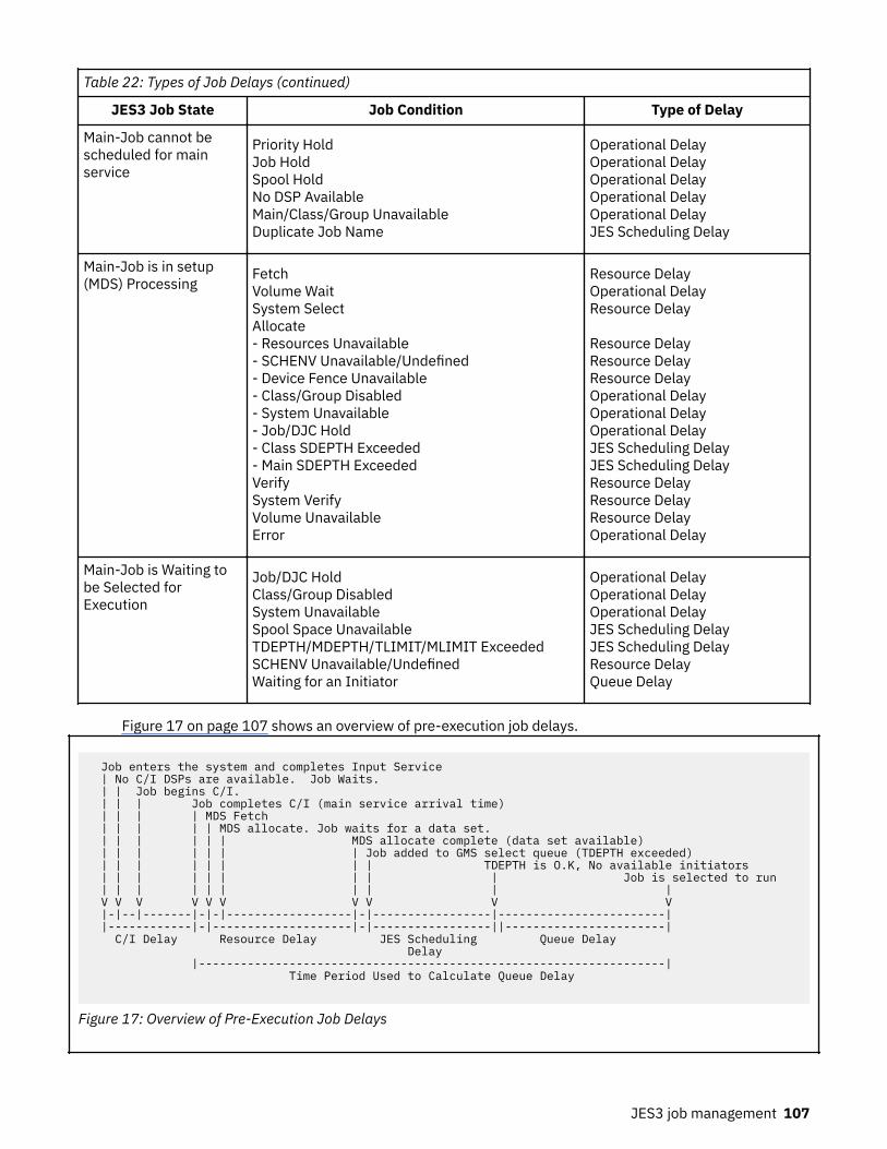
Table 22: Types of Job Delays (continued)
JES3 Job State Job Condition Type of Delay
Main-Job cannot bescheduled for mainservice
Priority HoldJob HoldSpool HoldNo DSP AvailableMain/Class/Group UnavailableDuplicate Job Name
Operational DelayOperational DelayOperational DelayOperational DelayOperational DelayJES Scheduling Delay
Main-Job is in setup(MDS) Processing
FetchVolume WaitSystem SelectAllocate- Resources Unavailable- SCHENV Unavailable/Undefined- Device Fence Unavailable- Class/Group Disabled- System Unavailable- Job/DJC Hold- Class SDEPTH Exceeded- Main SDEPTH ExceededVerifySystem VerifyVolume UnavailableError
Resource DelayOperational DelayResource Delay
Resource DelayResource DelayResource DelayOperational DelayOperational DelayOperational DelayJES Scheduling DelayJES Scheduling DelayResource DelayResource DelayResource DelayOperational Delay
Main-Job is Waiting tobe Selected forExecution
Job/DJC HoldClass/Group DisabledSystem UnavailableSpool Space UnavailableTDEPTH/MDEPTH/TLIMIT/MLIMIT ExceededSCHENV Unavailable/UndefinedWaiting for an Initiator
Operational DelayOperational DelayOperational DelayJES Scheduling DelayJES Scheduling DelayResource DelayQueue Delay
Figure 17 on page 107 shows an overview of pre-execution job delays.
Job enters the system and completes Input Service | No C/I DSPs are available. Job Waits. | | Job begins C/I. | | | Job completes C/I (main service arrival time) | | | | MDS Fetch | | | | | MDS allocate. Job waits for a data set. | | | | | | MDS allocate complete (data set available) | | | | | | | Job added to GMS select queue (TDEPTH exceeded) | | | | | | | | TDEPTH is O.K, No available initiators | | | | | | | | | Job is selected to run | | | | | | | | | | V V V V V V V V V V |-|--|-------|-|-|------------------|-|-----------------|------------------------| |------------|-|--------------------|-|-----------------||-----------------------| C/I Delay Resource Delay JES Scheduling Queue Delay Delay |-------------------------------------------------------------------| Time Period Used to Calculate Queue Delay
Figure 17: Overview of Pre-Execution Job Delays
JES3 job management 107

Defining service classes and performance goalsA service class is a group of work with the same performance goals, resource requirements, or businessimportance. When you define a service class to WLM, you also assign performance goals to the serviceclass.
Performance goals can be one of the following:Discretionary
Work is run when the system resources are available.Response Time Goal
A response time goal can be either an average response time or a response time and a percentile.Response time goals are measured from the time the job completes C/I processing (main servicearrival time) until it completes execution.
Conversion delay is still tracked by JES3, but it is not included as part of the goal. TYPRUN=HOLD timeis not included in either the conversion delay or in the response time calculation.
Velocity GoalVelocity is a measure of how fast work should run when ready, without being delayed for WLM-managed resources. For jobs in JES-managed job class groups, the definition of velocity is jobinitiation through job termination. For jobs in WLM-managed job class groups, velocity includes queuedelay (the amount of time waiting for an initiator). By including queue delay in the velocity calculation,WLM can determine whether adding another initiator will help a service class meet its performancegoals.
Figure 18 on page 108 illustrates response time/velocity goals.
* Input Service (Reader) <*********** - User Delay * * ** Converter/Interpreter * - Conversion delay * * ** Main Service * <********* - Operational delay (job hold, class disabled) * * - JES scheduling delay (class limits, duplicate * * job name) * Response * - Resource delay (resource affinity, JES3 setup) * Time * - Queue delay (waiting for an initiator) * <*********** * * * * Velocity WLM- ** Initiation <************* * managed Job * Velocity JES- * Class Groups * managed Job * * Class Groups * ** Execution <************* <*********** <*********** <********** Output Service* Purge
Figure 18: Response Time/Velocity Goals
Recommendations For Defining Service Classes
The following are general recommendations you should follow when defining service classes.
• Service classes should not include jobs in JES-managed and WLM-managed job class group. Doing soweakens the relationship between the number of WLM-managed initiators and the queue delay that isobserved. For example, if a velocity goal is used, queue delay is included in the velocity calculations forWLM-managed initiators. If a service class contains jobs in JES-managed and WLM-managed job classgroups, queue delay will be included in the velocity calculations for some jobs but not all of the jobs inthe service class.
• Service classes should be unique across a JESPLEX. If you run multiple JESPLEXs within a SYSPLEX,keep in mind that WLM policies are SYSPLEX-wide and WLM manages the performance goals for a
108 z/OS: JES3 Initialization and Tuning Guide

service class at a SYSPLEX level (for example, performance goals based on the SYSPLEX performanceindex). If a service class is shared between two JESPLEXs, it is possible for a service class to be meetingits goals from a SYSPLEX, but not meeting its goals in a particular JESPLEX within a SYSPLEX.
• If class limits are specified on the Class initialization statement, jobs in that class should map to a singleservice class. If jobs in the class map to multiple service classes, more initiators may be started thannecessary because each service class will be treated independently with respect to the class limits.When JES3 reports to WLM the number of eligible jobs in the service class, it will apply the class limitsto each service class individually.
Job Selection Algorithm for JES3-Managed InitiatorsWhen a job in a JES-managed job class group has completed processing in MDS, the job is placed in thequeue of jobs awaiting selection for execution. This queue is ordered by job priority, with the last jobs toarrive being placed last within the priority. Thus, the time at which a job completes setup processingpartly determines its place in the queue.
When a request for a job arrives from the JES-managed initiator, the job is ready to be selected forexecution. Jobs that are requested by JES-managed initiators are still queued by priority, but jobs that arerequested by WLM-managed initiators are queued by age to an appropriate service class queue.
JES-managed initiator job selection is driven by how you define job processing in the GROUP, CLASS, andSELECT initialization statements. All jobs classes are defined to JES3 by using the CLASS initializationstatement. Each such class is associated with a job class group that is defined using the GROUPinitialization statement. The GROUP initialization statement specifies the number of initiators to allocateon each system and how the initiators should be allocated and deallocated. A job class group can haveone or more job classes associated with it.
After an initiator starts, it asks the JES3 global processor for a job. JES3 then examines the GMS selectqueue associated with the initiators job class group to see if there are jobs that can be selected to run.After a job is selected, JES3 reads the job's control blocks and sends the initiator all the information itneeds to setup the job for execution. When the job completes execution, the initiator returns the job toJES3. JES3 then updates the job's control blocks to show that the job has completed execution.
For jobs requiring JES-managed initiators, JES3 controls the initiator selection process by firstdetermining whether the select mode on the processor on which the request originated includes theIORATE parameter (from the CLASS initialization statement) as a factor. This determination is made onthe basis of what CHOICE parameter on the SELECT initialization statement was specified. If CHOICE wasBMIX or FMIX, then IORATE is a factor in this job selection. If IORATE is a factor in this selection, the jobselection algorithm computes the best and alternate rates for later use. If the CHOICE parameter wasother than BMIX or FMIX, then IORATE is not a factor and best and alternates rates are not computed.
The best and alternate I/O rates are based on the total number of initiators with started jobs on theparticular processor, and on the JOBMIX parameter specified on the SELECT initialization statement forthis processor. For each number of active initiators, a set of jobs with low, high, and medium I/O rates isspecified by the JOBMIX parameter. When the I/O rate computation begins, it determines the number ofactive initiators, and from this, the number of jobs for low, high, and medium I/O rates that the JOBMIXparameter specifies for this number of started initiators. The low, high, and medium numbers specifiedduring initialization are the numbers of jobs that ideally should be executing for this total number of activeinitiators. The algorithm then computes which I/O rate (low, high, or medium) is farthest from the ideal, asspecified during initialization. The I/O rate that most needs to be increased to meet the ideal becomes thebest rate, and the one that needs to be increased second-most becomes the alternate rate. In case ofties, the choice favors low, then high, then medium for best or alternate. As far as I/O rate is a factor in jobselection, the choice favors the I/O rate that needs to be increased the most.
The job selection algorithm next moves to the queue of jobs ready for execution and looks up the first jobin the group of the requesting initiator. The algorithm determines whether this first job is in hold status,either as the result of an operator command or because it is part of a DJC network. If the job is in holdstatus, the algorithm determines whether it has reached the end of the group's selection span. The JSPANparameter on the GROUP initialization statement defines the span.
JES3 job management 109

If the job being tried as a candidate for job selection could be executed on the processor from which therequest originated, the algorithm determines the candidate's job class. The CLASS initialization statementparameters MDEPTH, MLIMIT, TDEPTH, and TLIMIT are all checked for this class. If any of these limits aremet or exceeded for this job candidate, the scan checks for JSPAN and BAR parameters on the GROUPstatement. If these are not exceeded, it moves to the next job candidate in this group and starts again.
The maximum number of job selection candidates examined in response to a job selection request isspecified by the JSPAN parameter on the GROUP initialization statement. If the number of jobs scannedas candidates for selection reaches the value specified by JSPAN, the algorithm terminates the jobselection pass. In this case, the initiator continues waiting, and the job-select request remains queued.
If the value specified by JSPAN has not been reached, the algorithm determines whether a priority barrieris effective at this point. If a priority barrier is reached, then the result is the same as if JSPAN has beenreached: no more jobs in the queue can be scanned.
If the job has a scheduling environment (that is, the SCHENV= keyword was specified on the JOBstatement), the job selection algorithm checks if the scheduling environment is available. If it is notavailable, the scan checks for the JSPAN and BAR parameters on the GROUP initialization statement. Ifthese are not exceeded, it moves to the next job candidate in this group and starts again.
The selection algorithm next determines whether this job can fit into the available logical storage of thisprocessor. If not, the algorithm checks whether the CHOICE parameter on the SELECT statement is set forFJOB (first job of the group in the queue). Specifying the FJOB parameter just tries the first job of thegroup; if it can be executed, it is selected, and if it cannot, no job is selected.
If the job selection candidate fits into storage on the processor and the CHOICE parameter is not FJOB,the algorithm looks back to the earlier determination of whether IORATE is to be considered in thisselection. If it is not, a suitable job has been found, and this job is returned to the requesting initiator. IfIORATE is a factor (CHOICE is specified as BMIX or FMIX), the algorithm compares the I/O rate of this jobwith its earlier determination for best I/O rate. If the I/O rate of this job is the same as the best I/O rate,this job is returned to the initiator as the selected job. If the I/O rate of this job is the same as thealternate I/O rate and the CHOICE parameter is set for FMIX, this job is returned to the initiator as the jobselected. If the job does not match the best or alternate I/O rate, the algorithm checks for JSPAN and BARand starts examination of the next job of the group on the queue.
Job Selection Algorithm for WLM-Managed InitiatorsWhen a job in a WLM-managed job class group has completed processing in MDS, the job is placed in thequeue of jobs waiting to be selected for execution by service class. This queue is ordered by main servicearrival time (i.e. when the job completed C/I processing). Unlike jobs in JES-managed groups, priority isnot used to order the jobs on the queue, because priority is one of the many criteria that can be used toassign a service class for a job. Because jobs are ordered by main service arrival time and not priority, thetime the job completes setup processing does not determine its place in the queue.
When a request for work arrives from a WLM-managed initiator, the source of the request narrows thechoice in two ways:
1. The service class identification of the initiator limits the choice to jobs with that service class.2. The processor on which the initiator is started limits the choice to jobs that can run on that processor.
Note: Even though WLM management operates at a job class group level, WLM-managed initiators selectwork by service class and not by job class group like JES-managed initiators. Therefore, the queue of workfor a particular service class can have jobs from different job class groups.
Unlike job selection for JES-managed groups, the following job selection parameters are ignored forselecting jobs in WLM-managed groups.
• IORATE on the CLASS statement• CHOICE on the SELECT statement• JOBMIX on the SELECT statement• LSTOR on the SELECT statement
110 z/OS: JES3 Initialization and Tuning Guide

• JSPAN on the GROUP statement• BAR on the GROUP statement
Note: Workload balancing parameters, such as CHOICE, JOBMIX, and LSTOR are ignored becauseworkload balancing functions are left to WLM and SRM.
When a WLM-managed initiator requests a job, each job in the service class queue is examined until a jobis found that is eligible to be selected for execution or until no jobs are left to run. JSPAN and BAR are notused to limit the number of jobs examined. The following job characteristics are examined when selectinga job:
• Is job selection suspended because a WLM service definition change has occurred, and JES3 is busyreclassifying jobs?
• Can the job run on the system on which the initiator is started?• Is the system on which the initiator is started, connected and online?• Is the job's group and class enabled on the system on which the initiator is started? Is the job held as a
result of an operator command or because it is part of a DJC network?• Is there available spool space in the spool partition that is assigned to the job? The spool partition that
is examined is one of the following:
– The spool partition specified by the SPART parameter– The spool partition assigned to the job class using the SPART parameter on the CLASS initialization
statement– The spool partition assigned to the system using the SPART parameter on the MAINPROC
initialization statement– The default spool partition
• Are any of the class limits exceeded as defined using the TDEPTH, MDEPTH, TLIMIT, and MLIMITparameters on the CLASS initialization statement?
• If the job has a scheduling environment, is the scheduling environment available on the system onwhich the initiator is started?
Deadline SchedulingDeadline scheduling is a technique that allows a user to schedule a job by time-of-day, week, month, oryear. The job's priority remains in force, but as the deadline approaches, JES3 increases the job's priority.Thus, deadline scheduling increases the likelihood that the job will be scheduled for execution by thespecified deadline.
Note: As a result of deadline scheduling, a job will be reclassified when its priority is changed. Dependingon the priority that is used in your installation's classification rules in the WLM policy, this may or may notcause a new service class to be assigned to the job Changing the priority as a result of deadlinescheduling does not affect when a job in a WLM-managed group is selected to run. Jobs waiting to beselected for execution by an WLM initiator are ordered by main service arrival time and not priority.
A deadline scheduling algorithm specifies how often and by what amount JES3 is to increase the job'spriority. You must specify the algorithm on a DEADLINE initialization statement. You can specify amaximum of 36 deadline scheduling algorithms.
To specify deadline scheduling for a job, the user must code the DEADLINE parameter on a //*MAINstatement. This parameter specifies the time or date by which the user wants the job scheduled. It alsospecifies which deadline scheduling algorithm JES3 is to use for the job.
The DEADLINE DSP controls the scheduling of these jobs. The DEADLINE DSP examines all the jobs in thedeadline queue and issues an ATIME macro instruction for the shortest time interval until a job prioritychange is required. Unless another job with a shorter time interval is placed in the queue, the DEADLINEDSP waits until the time expires. Then, the priority of the waiting job is increased to increase theprobability of the job being processed on time.
JES3 job management 111

If the operator presses the STOP button or enters an MVS QUIESCE command, deadline scheduling stops.When the system is restarted, the operator must reinitialize the DEADLINE DSP by entering the*START,DEADLINE command. Reinitializing the DSP resets the deadline scheduling internal clock to thecorrect time. If the DSP is not reinitialized, the clock continues from the time at which deadline schedulingstopped and jobs in the deadline queue are delayed by the amount of time the system was stopped orquiesced.
If no jobs are in the deadline queue, the DEADLINE DSP sets the ATIME macro instruction to expire atmidnight (as a default), and the DEADLINE DSP waits until it is canceled by the operator or until anotherdeadline job is placed on the queue.
Dependent Job ControlDependent job control (DJC) allows jobs to be executed in a specific order, as determined by jobdependencies. Job dependencies may occur because of data dependencies or may be defined to achievebetter device utilization or to manage job streams.
To define a DJC network, the user must include a //*NET control statement in the JCL stream for each jobin the network. The //*NET control statement specifies the dependency that must be satisfied before thejob can be scheduled for processing. Jobs normally must wait for scheduling until a predecessor jobcompletes. A predecessor job is a job that must complete execution before this job can be scheduled.Jobs that have one or more predecessor jobs are called successor jobs. (Nonstandard DJC jobs aredefined with the inclusion of //*PROCESS DJCPROC statements.) Jobs belonging to a DJC network cannotbe registered with automatic restart management.
For a complete description of the //*NET and //*PROCESS control statements, see z/OS MVS JCL User'sGuide.
Early Dependent Job Control (DJC) JCL Scan
The CI DSPs process the JCL for all jobs in a DJC network through the prescan phase, regardless of theprogress of predecessor jobs through the system. As a result, most JCL and control statement errors inthose dependent jobs can be detected and corrected, and the job can be resubmitted before its release.When the required predecessor jobs have indicated that dependent jobs can be released for execution, aPOSTSCAN DSP is subsequently scheduled to complete postscan processing.
Initializing the DJC Job Network
The first job of a given DJC network entering the system causes the specified DJC network to be definedto JES3. All subsequent jobs with the same DJC network identification become members of that DJCnetwork.
The first DJC job of a particular DJC network can use the DEVPOOL parameter of the //*NET controlstatement to reserve devices for the entire network. When reserving devices, the user can code theDEVPOOL parameter to refer to the requested devices by name. This parameter should refer to the namesdefined by the POOLNAMS parameter on the SETNAME initialization statement.
It is important to reserve devices for a DJC network if the DJC jobs pass data sets from one to another;this means that they have similar setup requirements. If devices are not reserved for a DJC network, theDJC jobs contend with other jobs in the system for the available devices when they enter setup. Since DJCjobs are normally held before setup and they are only released for setup when their predecessor jobshave completed, other jobs can take over the devices that the DJC network will soon need again. Bothvolume mounting operations and the time required by successor jobs to get through the system can bereduced by reserving the commonly required devices for the network. User exit IATUX24 allows you toexamine information coded on a //*NET statement. You can examine the network id and the list ofrequested devices. A return code allows you to accept or reject the device request.
Scheduling the DJC Job Network
The NHOLD parameter on the //*NET control statement specifies the number of predecessor jobs thatmust complete before the job is eligible for scheduling. If no NHOLD parameter is specified, then the jobis eligible for immediate scheduling. If the NHOLD parameter is specified or if the job is in an operator-
112 z/OS: JES3 Initialization and Tuning Guide

hold state, only the converter/interpreter and prescan phases of C/I service are scheduled. Postscanprocessing is suspended until the job is released when all predecessors complete execution.
It is possible to make a job eligible for device setup before its predecessor jobs complete execution. To dothis, code the NHOLD and RELSCHCT parameters on the job's //*NET statement. The values of theseparameters determine when the job becomes eligible for device setup.
The job becomes eligible for device setup when its NHOLD value is equal to or less than its RELSCHCTvalue. JES3 reduces the NHOLD value by 1 each time:
• A predecessor job completes execution• A job (the job need not be part of the DJC network) issues the following form of the DJC write-to-
operator message:
JESDJC1 jobname net-id
(The variable ‘jobname’ refers to the name of the job to be terminated; NHOLD values for successor jobswill be decremented.)
For more information about using this write-to-operator message, see “DJC Completion Option”.
If a job becomes eligible for device setup before its predecessor jobs complete execution, JES3 schedulesthe job up to but not including generalized main service. JES3 then places the job in DJC-hold status.
Modifying the DJC Job Network
Use the *MODIFY,N operator command to:
• Hold an entire DJC job network or a specific job within the network• Release an entire DJC job network or a specific job within the DJC network• Cancel an entire DJC network or a specific job within the DJC network
For additional information, see z/OS JES3 Commands.
Terminating the DJC Job Network
A DJC job network is purged when all of the following conditions are satisfied:
• All jobs in the DJC network are completed• There are no missing successor jobs in the DJC network• There are no missing subnetworks• The job pending count is equal to zero
The job pending count is the number of abended jobs that have been resubmitted, or have abended withthe ABCMP=KEEP parameter specified on the //*NET statement. Specifying this parameter ensures thatthe DJC network will be retained in the system until the job is resubmitted and completed normally oruntil the DJC network is flushed by operator commands.
DJC Completion Option
A job completion option is available for the standard DJC job. A problem program may issue a write-to-operator (WTO) message which invokes DJC updating when the message is received. Thus, a job canbecome eligible for device setup before its predecessor jobs complete execution.
The WTO text format to invoke this option is:
JESDJCx jobname net-id
This format is positionally dependent. JES must begin in position 1; jobname, which is the name of the jobto be terminated, must be 1 to 8 characters and must begin in position 9; net-id must be 1 to 8 charactersand must begin in position 18. Comments must begin in position 26. The x in JESDJCx must be specifiedas 1 for normal job completion or as 2 for abnormal job completion.
JES3 job management 113

Nonstandard DJC Job Processing
A nonstandard DJC job contains //*NET and //*PROCESS statements. For nonstandard DJC jobs, a //*PROCESS DJCPROC statement is required only when a //*PROCESS MAIN statement is not included inthe job stream. If a //*PROCESS DJCPROC statement is included without a //*NET statement, an errormessage is issued and the job is flushed. The position of the //*PROCESS DJCPROC control statementsindicates when the job is considered complete to DJC, that is, when its successor jobs should beconsidered for scheduling. A //*PROCESS DJCPROC statement has no parameters and must be precededby a //*NET control statement. Note that in a standard job not issuing a DJC WTO message, DJCprocessing occurs after main service has completed.
With the use of the //*PROCESS DJCPROC statements or the DJC WTO message, job completion is alwaysconsidered normal completion.
For more information on DJC, see z/OS MVS JCL User's Guide.
Controlling Job SelectionThe JES3 initialization stream can be used by the system programmer to tailor JES3 job selection processto meet installation requirements.
Determining main eligibility
Main eligibility is determined in the following stages:
1. Input service determines the mains that can execute the job when either the SYSTEM or SYSAFFparameter on the JOB control statement, or the SYSTEM parameter on the //*MAIN control statement,and the job class are analyzed.
2. JES3 MDS selects mains by location of non-shared devices and permanently resident volumes anddata sets.
3. The assignment of removable devices by the job can again restrict the mains eligible to run a job.4. The availability of the job's scheduling environment can restrict the mains that are eligible to run a job.
For these reasons, jobs in a JES3 loosely coupled complex are selected for execution by processoreligibility (an implied attribute), the explicitly stated class, and priority attributes for scheduling.
Determining Job Eligibility
After a job is set up, it becomes eligible for selection by GMS. GMS determines which jobs to selectaccording to the SELECT mode under which the main is running. This gives the I/O rate (CHOICE) for jobsto select and the classes and job class groups eligible for selection for this processor. GMS considers allclass constraints (MLIMIT, TLIMIT, TDEPTH, and MDEPTH) in further limiting the jobs that it can select.
Controlling the Job Mix on Each Processor
The system programmer can specify the IORATE parameter of the CLASS initialization statement todescribe the I/O rate of jobs in the class. (A low, medium, or high I/O rate can be determined by SMF orperformance measurement.) By properly mixing jobs with different I/O-to-processor ratios, thethroughput can be increased over that obtained by random mixing. IORATE is ignored during job selectionfor jobs in WLM-managed job class groups.
Defining the job selection environment
Through the use of the MVS JOB statement, the //*MAIN JES3 control statement, and several JES3initialization statements, you can define the JES3 job selection environment. You can use the GROUPstatement to define a job class group, to assign resources (main and I/O devices), and to define what typeof initiator should process jobs in the group (JES-managed initiators or WLM-managed initiators). TheCLASS statement allows you to define job classes, give them a priority, and specify them as members ofjob class groups. The user can use the MVS JOB statement or the //*MAIN statement to assign a jobpriority and a job class.
114 z/OS: JES3 Initialization and Tuning Guide

JES3 assigns each main a job selection mode. The SELECT parameter on the MAINPROC initializationstatement tells JES3 which mode to assign. The job selection mode can be dynamically changed by aJES3 *MODIFY command if alternate selection modes are defined at initialization.
The effect of partitioning a processor complex should be considered when defining the job selectionenvironment for a main. If one side of a processor complex is partitioned and taken offline, some jobs maynot be able to run using the remaining resources. Less storage is available and particular devices, if onlyattached to the side that has been partitioned off, may no longer be accessible. Alternate selection modesshould be defined and used to adjust the amount of batch work scheduled as resources are lost orregained through partitioning.
Figure 19 on page 116 shows two jobs of class C5 in the input stream, and each of these jobs references aspecific I/O device number as a DD UNIT parameter. One of these jobs references a non-shared deviceand, therefore, must execute on the JES3 local processor (designated WORKCPU) in this example. Theother job of class C5 references a specific I/O device number that is shared between the JES3 globalprocessor and the JES3 local processor. Since class C5 is assigned to group G2 and has executionresources allocated to both processors, the job may run on either processor.
JES3 job management 115

Figure 19: JES3 Job Selection Environment
116 z/OS: JES3 Initialization and Tuning Guide

Default Job Selection
Jobs are selected for execution by the GMS algorithms. The specific path followed through GMS isdetermined by the parameters specified in the MAINPROC, SELECT, GROUP, and CLASS initializationstatements.
JES initiator management is then used, and jobs are selected by priority only, in first-in-first-out order. Inthis case, two JES-managed initiators are started on each processor, and default selection mode, group,and class are established with the name JS3BATCH. If more initiators are required, the dedicated initiatorcount for the default group can be increased with a *MODIFY command, or a GROUP initializationstatement for JS3BATCH can be specified with dedicated initiator counts for each processor. If you wantWLM initiator management to be used for the default group, you can switch from JES to WLM initiatormanagement with a *MODIFY command, or a GROUP initialization statement for JS3BATCH can bespecified with MODE=WLM.
For JES-managed initiators, the primary decision to be made is the number of initiators to be assigned toeach group. This, in turn, determines the number of jobs that can run concurrently on each processor. Thededicated initiator counts, therefore, should not be set substantially above the job processing capability ofa processor.
Starting and Stopping Initiators
The initiator allocation and deallocation options specified in the EXRESC parameter of the GROUPinitialization statement only applies to JES-managed initiators (MODE=JES). These options control theconditions under which JES-managed initiators are started and stopped. For WLM-managed initiators, thestarting and stopping of initiators is under control of WLM, and is based on information from the WLMpolicy, available system capacity, and information from JES3 related to the backlog of jobs. Initiatorallocation and unallocation options can be defined for WLM-managed job class groups; however, theseoptions will be ignored.
Demand or dynamic initiator allocation occurs when jobs are available for execution and when the jobclass group they are in becomes enabled. (Dynamic allocation is used to allocate JES-managed initiatorswhen the first job of the group in the queue is eligible for main scheduling; demand allocation is used toallocate JES-managed initiators as they are needed.) Demand or dynamic deallocation for JES-managedinitiators occurs when no jobs are available for execution.
If jobs are not conntinually available for execution, the overhead of starting and stopping initiators may beundesirable. In this case, the IPL allocation option should be used to allocate execution resources duringprocessor connection, or the MANUAL allocation or deallocation option should be specified to indicatethat all execution resources are not to be allocated or released until the operator disables the job classgroup with a *MODIFY command. The allocation and deallocation options should be chosen to maintaininitiator availability and minimize start/stop overhead.
The overhead of starting and stopping initiators can also be avoided by using WLM-managed initiators(MODE=WLM specified on the GROUP initialization statement). When a new initiator needs to be assignedto a service class, a new initiator address space is not necessarily started. Instead, WLM maintains a poolof initiator address spaces and assigns them dynamically to the service classes when needed. Only ifthere are no available initiators is a new initiator address space started. When WLM decides that there aretoo many initiators assigned to a service class, it does not stop the initiator address space; instead, itreturns the initiator to the pool of idle initiator address spaces. After a period of time, the idle initiatoraddress spaces will be stopped.
Manual or dynamic allocation and deallocation options are preferablecompete in an JES initiator managedenvironment, where both of the following are true:
• Work is available for processing on a predefined schedule in a specific window; for example, work isavailable for processing at 4 PM to be completed by 6 AM the following morning.
• Work in the group is available in sufficient quantities to prevent unnecessary starting and stopping ofinitiators.
For work that arrives sporadically, DEMAND allocation and deallocation options are preferable.
JES3 job management 117

Defining Logical Storage for Processors
The LSTOR parameter on the SELECT initialization statement allows you to:
• Use dynamic central storage more efficiently• Reduce the probability of excessive paging (thrashing)
Note: LSTOR parameter on the SELECT initialization statement is ignored in job selection for jobs that arein WLM-managed job class groups. For jobs in JES-managed job class groups the LSTOR parameters isuseful in improving job selection efficiency.
JES3 schedules jobs on processors according to their available logical storage. When jobs are scheduled,their logical storage requirements are subtracted from the processor's logical storage; if sufficient logicalstorage is not available to schedule a job, it is not scheduled.
A job's logical storage requirements are determined either by the LREGION parameter on the //*MAINcontrol statement or by taking a percentage of the region size of the job's largest step. To specify thepercentage, code the LSTRR parameter on the CLASS initialization statement.
Attention: Installations that run jobs specifying more than 16 megabytes for the REGION parameter onthe JOB or EXEC JCL statement should be aware that JES3 logical storage scheduling considers theregion size for those jobs to be 16 megabytes exactly. If jobs require a region size greater than 16megabytes, logical storage scheduling should be disabled by specifying LSTRR=0 on the appropriateCLASS initialization statement(s).
The combination of methods chosen to control central storage utilization can lead to one of the followingoperating conditions:
• Central storage is underused, and throughput is limited regardless of any other tuning.• Central storage is fully used, and paging is optimum. This condition allows maximum throughput.• Central storage is fully used, but paging is excessive. Again, throughput is limited.
The third condition, excessive paging, can be caused by the system programmer specifying a high LSTORvalue, allowing JES3 to schedule too many jobs on the processor. Excessive paging can also be caused bythe application programmer specifying a low LREGION value or by defaulting to a low LSTRR percentage(defined by the system programmer).
To obtain maximum throughput, start with underutilization of central storage and gradually increaseutilization. Until you optimize throughput, you should retain full control of the logical storage parameters.Application programmers should not use the LREGION keyword on the //*MAIN statement during thisphase, and the system programmer should set the LSTRR keyword on the CLASS statement to 99. Themaximum value that you can specify on the LSTOR keyword is 32,767.
These guidelines should provide reasonable central storage utilization while the actual central storagerequirements (working sets) are determined for typical jobs and job classes. When working setmeasurements are obtained (through SMF data and other performance measurement tools) and identifiedfor the various jobs and classes, the LREGION and LSTRR parameters can be used to fine-tune theprocessor throughput.
Job classes should be defined for low, medium, and high I/O rates. If this is not done, all jobs are giventhe default I/O rate (medium). To use the I/O rate, specify the job selection preference in the CHOICEparameter on the SELECT statement. If I/O rate is considered in scheduling, GMS attempts to select jobsthat produce the required job mix (as specified in the JOBMIX parameter of the SELECT initializationstatement). Because the LREGION parameter on the //*MAIN JES3 control statement overrides the LSTRRparameter, use installation exit IATUX33 to delete the LREGION parameter when you want logical storagescheduling disabled.
Controlling Job SchedulingThe GMS function of JES3 allows the system programmer to define a set of parameters that determine thescheduling of jobs on each processor in the JES3 complex. Each processor can have a unique set ofscheduling parameters.
118 z/OS: JES3 Initialization and Tuning Guide

MAINPROC, SELECT, CLASS, and GROUP initialization statements allow the system programmer to controlthe key variables in the job scheduling and execution process. The dynamic interaction of thesestatements defines a job selection mode that controls job selection in a specified way. The followingparameter description provides an overview of these controls.
Assigning a Job Selection Mode
The MAINPROC statement describes each processor. The SELECT parameter on this statement specifiesthe name of the job selection mode to be assigned initially to the processor. The name designated withthe SELECT parameter must also be specified in the NAME parameter of a SELECT initialization statement.
If the SELECT parameter is omitted, a selection mode is established using the SELECT statement defaultvalues. (The default selection mode is designated by JES3 as JS3BATCH.)
Defining Job Selection Parameters
The SELECT statement defines the job selection parameters for each job selection mode. The jobselection mode is assigned to a processor by the SELECT parameter on the MAINPROC statement. Afterinitialization, the system operator can change the association of processors with selection modes by usingthe *MODIFY command.
The system programmer can control the number of jobs that are candidates for allocation by setting theSELECT statement SBAR parameter. The SBAR parameter specifies a job priority that is a barrier to maindevice scheduling:
• If its full allocation requirements cannot be satisfied, a job with a priority greater than the barrier canreserve available JES3-managed resources (devices, volumes, and data sets) to prevent lower priorityjobs from obtaining them.
• If a resource is reserved, only a job of the same priority or higher than the job that reserved the resourcecan allocate it.
• If a volume or data set is reserved, another job with compatible references (such as a share reference toa direct-access volume) can use it.
• If SBAR=PRTY is specified, the priority of the first job that cannot be set up is the barrier value.
For jobs in JES-managed job class groups (MODE=JES specified on the GROUP initialization statement),the CHOICE and JOBMIX parameters on the SELECT statement can be used to specify job selectioncriteria (based on the size of the job and its I/O rate) to control the order of job selection on a processor.JES3 uses the specified scheduling choice to select the most suitable jobs for execution. For jobs in WLM-managed job class groups (MODE=WLM specified on the GROUP initialization statement), JOBMIX andCHOICE are ignored for purposes of job selection.
Aging is the process of increasing a job's priority whenever an unsuccessful attempt is made to allocatethe job's requirements. Although jobs flow through the priority queues in first-in first-out order, only thejob that is first on a priority queue is eligible for aging. The system programmer controls aging by settingthe following parameters on the SELECT statement:
• MAGER: Specifies the number of times a job must be eligible for aging (because of unsuccessful jobselection) before its job priority is actually increased. (For example, MAGER=10 means that a job mustbe passed over for job selection 10 times while it is at the top of its priority queue before it is put at thebottom of the next higher priority queue.) If this parameter is omitted or if MAGER=0 is specified, noaging is performed. (For jobs in WLM-managed job class groups, MAGER is ignored. Jobs destined forWLM-managed initiators are ordered on the queue by main service arrival time.)
• MAGEL: Limits the priority that can be reached (because of unsuccessful job selection attempts). Forexample, MAGEL=10 means that a job is not aged if its priority is 10 or greater.) If this parameter isomitted, jobs are not aged past priority 14.(For jobs in WLM-managed job class groups, MAGEL isignored. Jobs destined for WLM-managed initiators are ordered on the queue by main service arrivaltime.)
• SAGER: Specifies the number of times that a job must be eligible for aging (because of unsuccessfulresource allocation) before its job priority is actually increased. If this parameter is omitted or if
JES3 job management 119

SAGER=0 is specified, no aging is performed. (SAGER is also used for jobs in WLM-managed job classgroups because these jobs are in MDS allocation where jobs are ordered by priority.)
• SAGEL: Specifies an aging priority limit (0-15) beyond which a job cannot be aged during job setup.(SAGEL is also used for jobs in WLM-managed job class groups because these jobs are in MDS allocationwhere jobs are ordered by priority.)
The JES3-managed resource allocation (setup of devices, volumes, and data sets) for each job must becompleted before the job is eligible for execution. The system programmer controls the executionqueueing process by setting the following parameters on the SELECT initialization statement:
• SDEPTH: Specifies the maximum number of jobs (requiring mountable devices) that can be set up at onetime for each processor. SDEPTH influences MDS allocation in two ways: First, SDEPTH can be used tolimit the number of jobs set up for a processor; this should be done carefully to avoid delaying jobexecution. If SDEPTH is omitted, a value of 255 is assumed. Second, SDEPTH causes MDS to set upmore work for one processor than another. MDS biases processor selection for setup toward theprocessor that is most below its SDEPTH. Therefore, by making the SDEPTH values different for eachprocessor, a setup bias initially exists toward processors with higher SDEPTHs. MDS prefers the higherSDEPTH processors for setup until all processors are at equal differences from their SDEPTH values.Biasing setup toward certain processors may be required because of device availability (if devices arenot totally shared) or to keep a larger queue of jobs available for a fast executing processor.
• INCR: Specifies a number that is added to the priority of the job when it is set up. This parameterexpedites the processing of jobs when devices have been assigned to them. (For example, if a job has apriority of 5 when it is set up, and INCR=4 is specified, the job's priority is increased to 9 after thedevices have been allocated and set up.) If this parameter is omitted, a job's priority is increased by oneafter setup.
• INCL: Sets a limit to the priority assigned when the job is set up. If this parameter is omitted, jobpriorities are not increased past priority level 14 by setup.
Note: For jobs in WLM-managed job class groups, the INCR and INCL parameters will not expedite jobselection when a job has been set up. Jobs in WLM-managed job class groups are ordered by main servicearrival time, not by priority when waiting to be selected to run.
Defining JES3 Job Classes
The CLASS statement defines the characteristics of the JES3 job classes. Up to 255 job classes can bedefined. A CLASS statement must define each job class that appears on the JOB or //*MAIN controlstatement. If an undefined class is specified, the job is canceled. If a class is not specified on a JOB or //*MAIN control statement, the default class is used.
The system programmer controls class execution limits and limit dependencies by setting the followingparameters on the CLASS statement (or by using the *MODIFY,C=class command to change theparameters):
• SDEPTH: Sets the maximum number of jobs requiring mountable devices (0 to 255) that can be set up atone time. If the SDEPTH parameter is omitted, no SDEPTH default is assumed for this class. (A typicaluse of SDEPTH would be to prevent overuse of devices by limiting the number of jobs that could be setup at one time in test class.)
• TDEPTH: Sets the maximum number of jobs of this class (0 to 255) that can execute in the total JES3complex at one time. If the TDEPTH parameter is omitted, no TDEPTH default is assumed for this class.
• MDEPTH: Sets the maximum number of jobs of this class (0 to 255) that can execute on a givenprocessor at one time. Each processor name specified in this parameter must also be specified on theNAME parameter of a MAINPROC initialization statement. If the MDEPTH parameter is omitted, noMDEPTH default is assumed for this class.
• TLIMIT: Specifies the maximum number of jobs of other job classes that can execute in the total JES3complex and still allow jobs in this class to be scheduled. If any class limit is exceeded, no more jobs inthis class are scheduled; that is, jobs in this class are scheduled only when the number of jobs runningfrom other classes is equal to or less than the assigned limit. Each class name specified in this
120 z/OS: JES3 Initialization and Tuning Guide

parameter must also be specified on the NAME parameter of another CLASS statement. If the TLIMITparameter is omitted, no TLIMIT default is assumed for this class.
• MLIMIT: Specifies the maximum number of jobs of other job classes that can execute on a givenprocessor and still allow jobs in this class to be scheduled. If any class limit is exceeded, no more jobsin this class are scheduled on the given processor; that is, jobs in this class are scheduled only when thenumber of jobs running from other classes is equal to or less than the assigned limit. Each class namespecified in this parameter must also be specified on the NAME parameter of another CLASS statement.If the MLIMIT parameter is omitted, no MLIMIT default is assumed for this class.
Note:
1. TDEPTH, TLIMIT, MDEPTH, and MLIMIT are used for WLM-managed job class groups and JES-managed job class groups. However, keep in mind that JES3 applies the class limits to each serviceclass separately during sampling. If you define class limits for a job class, and the jobs in the class areassigned to more than one service class, more initiators may be started than can actually run jobs.When class limits are used, it is suggested that all jobs in the class be assigned the same service class.
2. For started tasks, all CLASS initialization statement parameters are ignored except the following:
• JESMSG= to allow or suppress writing to JESMSGLG data sets for the started task.• SPIN= to allow or suppress the spin off of the JESMSGLG and JESYSMSG data sets for a long running
job.• Job class group name (GROUP parameter)• Device fencing (EXRESC and DEVPOOL parameters on the GROUP initialization statement)• Spool partitioning (SPART parameter)• Track group allocation (TRKGRPS parameter)
Grouping JES3 Job Classes
The GROUP initialization statement defines the resources available to a group of JES3 job classes. Amaximum of 255 groups can be defined. The system programmer specifies whether jobs in the group willrun under JES-managed initiators or WLM-managed initiators as specified on the MODE= parameter.
The EXRESC parameter defines the execution resources (initiators and devices) dedicated to the group,and also defines the systems where jobs in the group will run. Devices assigned to the group satisfyrequests for mountable volumes (not permanently resident) from jobs within the group. The EXRESCparameter should be repeated for each processor's execution resources. If the execution resourcerequirements are the same for all processors, the EXRESC parameter can be specified once on the GROUPstatement with a processor name of *ALL.
The EXRESC parameter also defines the initiator allocation and deallocation options (see “Starting andStopping Initiators” on page 117). For WLM-managed job class groups, the initiator related options (thatis, the number of initiators and allocaiotn and deallocation options) can be specified, but they will beignored. If the job class group is later modified so that JES initiator management is used, the initiatorrelated options will take effect.
The BAR parameter on the GROUP statement specifies a job priority used as a barrier to the generalizedmain scheduling process; it determines when no more jobs should be scheduled on an associatedprocessor. Within a job class group, no jobs with priorities lower than the barrier are run until all jobs withpriorities higher than the barrier have run. BAR can limit job scheduling because of processingrequirements (such as, a job that cannot obtain sufficient storage on a processor or a job that isincompatible with the current job mix under a best-mix scheduling algorithm). If BAR=PRTY is specified,the priority of the first job that cannot be scheduled is the barrier value. BAR=16, the default, means thatthere is no priority barrier for the group.
Note: A class can be assigned to a new job class group with the *MODIFY,C=cls,GROUP=grp command.This is useful if you have multiple job classes assigned to a group and you want to test WLM initiatormanagement for one of the classes in the group. You can use the *MODIFY,C=cls command to switch one
JES3 job management 121

of the job classes to a WLM-managed job class group without changing initiator management for the otherclasses in the group.
Automatic Restart Management
Automatic restart management is an MVS recovery function that can improve the availability of specificbatch jobs or started tasks. When a job or task fails, or the system on which it is running fails, automaticrestart management can restart the job or task without operator intervention. To be eligible for restartunder automatic restart management, a batch job or started task must register with automatic restartmanagement.
See z/OS MVS Setting Up a Sysplex for information about setting up and using the automatic restartmanager.
The following are some JES3-specific items to consider when using automatic restart management:
• When a job or system fails and the job is restarted by automatic restart management, all non-spinsysout data sets created during the previous execution are deleted.
If you want to make a sysout data set available for JES3 output service processing when the data set isclosed, use the FREE=CLOSE JCL option (or the corresponding dynamic allocation option). Automaticrestart management will not delete such data sets when the job is restarted by automatic restartmanagement.
If you want to retain a sysout data set that was still open and not yet closed at the time of the failure,use the SPIN=UNALLOC JCL option (or the corresponding dynamic allocation option). Using this optioncauses the data set to be unallocated and made available to JES3 at job termination time (that is, whenthe job or system initially fails and the job is restarted).
Table 23 on page 122 summarizes the use of the FREE=CLOSE and SPIN=UNALLOC options and theeffect they have on sysout data created by automatic restart management-registered jobs:
Table 23: FREE=CLOSE and SPIN=UNALLOC Effect on SYSOUT Created by Automatic RestartManagement
Options Used SYSOUT Data Set Status atTime of Automatic RestartManagement
JES3 Processing
FREE=CLOSE Closed The data set is unallocated andspun-off when closed by the job.
FREE=CLOSE Open The data set is deleted by JES3.
SPIN=UNALLOC Closed The data set is unallocated andspun-off at job end.
SPIN=UNALLOC Open The data set is unallocated andspun-off at job end.
FREE=CLOSE andSPIN=UNALLOC
Closed The data set is unallocated andspun-off when closed by the job.
FREE=CLOSE andSPIN=UNALLOC
Open The data set is unallocated andspun-off at job end.
Note: Sysout data sets created and maintained by JES3 (for example, JESMSGLG, JESYSMSG, JESJCL)are not deleted when a job is restarted by automatic restart management.
• You cannot use the JES3 Dump Job (DJ) facility to dump jobs that are waiting for restart by automaticrestart management.
• You cannot register jobs that are a part of a dependent job control (DJC) network with automatic restartmanagement.
122 z/OS: JES3 Initialization and Tuning Guide

• Failure options specified on the following parameters are ignored for jobs registered with automaticrestart management.
– FAILURE keyword on the CLASS initialization statement– FAILURE keyword on the STANDARDS initialization statement– FAILURE keyword on the //*MAIN JECL statement
If a job is registered with automatic restart management at the time of a system failure, automaticrestart management determines whether the job is restarted regardless of the value specified on theFAILURE keyword.
• Any job registered with automatic restart management can be restarted only within a single JES3complex. IBM recommends defining only one JES3 complex within a sysplex.
Output ServiceOutput service executes on the global and processes SYSOUT data sets destined for:
• JES3 managed devices• PSF managed devices• System Application Printer Interface (SAPI) applications• NJE (BSC and SNA)• Process SYSOUT (PSO)
The output service driver receives control after a job completes breakdown in main service, after a jobspins off an output data set, or after JES3 spins off an output data set.
JES3 output service performs three distinct functions:
• Queueing output• Scheduling output• Writing output
Queueing OutputNormally, output data produced by a job is placed in one of three output service queues when the jobterminates. Spin-off data sets are placed in an output queue while the job is still in execution. The threeoutput queues are:
• MVS/BDT work queue (Q=BDT): This queue contains SNA/NJE networking job or networking systemoutput streams. MVS/BDT sends these job or system output streams to the proper node within aSNA/NJE network. You can use JES3 operator commands to hold, release, or cancel networkingrequests from the queue.
• Output service writer queue (Q=WTR): This queue contains data sets waiting for output processing byJES3 managed devices. Output service automatically selects data sets for processing based on theirselection characteristics such as output class, output priority, and output device-related requirements.You can use JES3 commands to place these data sets in operator-hold status. You can also use JES3commands to modify a data set's selection characteristics or move the data set to the HOLD queue.
Note: Process SYSOUT and System Application Printer Interface can also process work on the outputservice writer (WTR) queue.
• Output service hold queue (Q=HOLD): This queue contains data sets that are awaiting output processingby other than JES3-managed devices. These data sets must be processed by the function for which theyare held (System Application Printer Interface (SAPI) application, external writer or TSO). The functionthat processes the data set can then change data set characteristics, release it for JES3 processing, orcause JES3 to purge it. If necessary, the operator can force a JES3 writer to process the data set orissue a modify (*F) command to move the data set to the WTR for JES3 device processing.
JES3 job management 123

You can use the JES3 *INQUIRY U and *MODIFY U commands to inquire about, modify, or delete datasets on the writer, hold, or BDT queue. For information about using these JES3 commands, see z/OS JES3Commands.
The RESQUEUE entry for the job to be processed by the queueing function is placed on a queue of outputservice work. When the queueing function receives control, it dequeues the next job on the work queue.
The queueing function of output service accesses the job data set (JDS) for the job or for the spin datasets of a job. The queueing function builds output scheduling elements (OSEs) from the JDS. One OSE isbuilt for each group of data sets that have unique writer requirements.
The information in an OSE for output data sets on the writer queue comes from:
• JCL parameters on the SYSOUT DD and OUTPUT JCL statements for the job (The installation can changethese parameters during input service by coding installation exit routine IATUX34 for the SYSOUT DDstatement and installation exit routine IATUX44 for the OUTPUT statement.)
• The //*FORMAT JES3 control statements for the job (The installation can change these statementsduring input service by coding installation exit routine IATUX33.)
• The SYSOUT class table (defined by SYSOUT initialization statements)
Note: The installation can change the characteristics in the OSE by coding the installation exit routine,IATUX19.
Information from //*FORMAT control statements is not included in OSEs for data sets on the hold queue.
When moving data sets from the hold queue to the writer queue, default and direct //*FORMATstatements are applied to the SYSOUT characteristics of the SYSOUT on the writer (WTR) queue.
The OUTSERV initialization statement specifies default values for information not provided on other JES3initialization statements or on JCL statements. If the OUTSERV initialization statement parameters are notoverridden, the default values specified are applied to all jobs entered in the system. You override theOUTSERV initialization statement parameters with appropriate parmaters on JCL or through particularDEVICE initialization statement parameters for those devices producing output. See z/OS JES3Initialization and Tuning Reference for detailed descriptions of the OUTSERV and DEVICE initializationstatements and their relationship to the JCL of jobs.
Override sequences for output data set information
For the output parameters of a data set, you can override the OUTSERV initialization statementparameters. The method used to override the parameters depends on whether OUTPUT JCL statementsor //*FORMAT JES3 control statements are specified for a data set, and whether the references areexplicit or by default. JES3 does not merge the information from the OUTPUT and //*FORMAT statementsthat refer to the same data set. Under certain circumstances (explained below), JES3 creates separateOSEs from the two types of statements.
Table 24 on page 124 shows the JES3 defined defaults that can be overridden.
Table 24: JES3 DEFINED DEFAULTS - Overriden by OUTSERV Initialization Statement.
DEFAULT PRINT PUNCH
Carriage 6 0
CDSTOCK N/A 5081
CHARS GS10 0
FLASH NONE,255 0,0
FORMS 1PRT 1PRT
MODIFY NONE,'0' 0,'0'
STACKER C 0
124 z/OS: JES3 Initialization and Tuning Guide

Table 24: JES3 DEFINED DEFAULTS - Overriden by OUTSERV Initialization Statement. (continued)
DEFAULT PRINT PUNCH
TRAIN PN PN (hard coded)
Note:
1. PROCESS MODE, which cannot be set in the INISH deck is set to 'LINE' for PRINT and to '0' forpunch.
2. '0' indicates the character 0 (hex 'F0')
Override sequence with “Direct” OUTPUT JCL statements for WTR queue and hold queue
A “direct” OUTPUT JCL statement is one that is explicitly referenced by the OUTPUT parameter of aSYSOUT DD JCL statement for a data set, or an OUTPUT JCL statement that specifies the JESDSparameter. If there is a "direct" OUTPUT JCL statement for the data set, the OUTSERV initializationstatement parameters are overridden by the following sources:
1. SYSOUT class table: This table is constructed from the parameters on the SYSOUT initializationstatement.
2. “Direct” OUTPUT JCL statement: The values specified on the direct OUTPUT JCL statement override thevalues specified by source 1 (above).
3. SYSOUT DD JCL statements: The values specified on the SYSOUT DD JCL statements override thevalues specified by sources 1 and 2 (above).
EXAMPLE
This example shows the override process using the FORMS parameter on the OUTSERV initializationstatement and “direct” OUTPUT JCL statement.
OUTSERV,FORMS=1PRT SYSOUT,CLASS=F,FORMS=3PRT ----> For WTR Q SYSOUT,CLASS=F,FORMS,3PRT,HOLD=EXWTR ----> For HOLD Q
Under these conditions, the following job is run:
//MARIOA JOB MSGLEVEL=(1,1),MSGCLASS=F //OUT1 OUTPUT CHARS=GS14,FORMS=2PRT,DEFAULT=NO //STEP1 EXEC PGM=IEBDG //SYSPRINT DD SYSOUT=(F,,4PRT),OUTPUT=*.OUT1 //SYSUT2 DD SYSOUT=F,DCB=(LRECL=80,RECFM=FB,BLKSIZE=80), // OUTPUT=*.OUT //SYSIN DD * DSD OUTPUT=(SYSUT2) FD NAME=FIELD1,LENGTH=80,STARTLOC=1,PICTURE=5,'MARIO',FILL=x'40' CREATE QUANTITY=10,NAME=FIELD1 END /*
Table 25 on page 125 illustrates the override process for this example.
Table 25: Output parameter overrides using a direct OUTPUT JCL statement for WTR and HOLD queue.
Data Set
FORMSInitialValue inOUTSERVStatement
Order of FORMS Overrides
FORMSFinal Value
CHARSFinalValue
1. SYSOUT,CLASS=F
2. OUTPUTFORMS=2PRT
3. DD forSYSPRINT
SYSPRINT 1PRT 3PRT 2PRT 4PRT 4PRT GS14
JES3 job management 125

Table 25: Output parameter overrides using a direct OUTPUT JCL statement for WTR and HOLD queue. (continued)
Data Set
FORMSInitialValue inOUTSERVStatement
Order of FORMS Overrides
FORMSFinal Value
CHARSFinalValue
1. SYSOUT,CLASS=F
2. OUTPUTFORMS=2PRT
3. DD forSYSPRINT
SYSUT1 1PRT 3PRT 2PRT n/a 2PRT GS14
JESJCL 1PRT 3PRT n/a n/a 3PRT GS10
JESMSGLG 1PRT 3PRT n/a n/a 3PRT GS10
JESYSMSG 1PRT 3PRT n/a n/a 3PRT GS10
JES3 builds one OSE for each direct OUTPUT JCL statement referring to a data set. A copy of the outputdata set for each OUTPUT statement is made available for processing. Each copy is formatted accordingto the processing options specified on the OUTPUT statement that produced it.
Override Sequence with Direct //*FORMAT JES3 Control Statements For WTR Queue
A “direct” //*FORMAT JES3 control statement is one that uses the DDNAME parameter to explicitlyreference a specific data set (that is, having the format //*FORMAT xx,DDNAME=xxxx). If there is a direct //*FORMAT statement, the OUTSERV initialization parameters are overridden by the following sources:
1. SYSOUT class table: This table is constructed from the parameters on the SYSOUT initializationstatement.
2. SYSOUT DD JCL statements: The values specified on the SYSOUT DD JCL statements override thevalues specified by sources 1 (above).
3. //*FORMAT xx,DDNAME=xxxx JES3 control statement: The values specified on the direct //*FORMATstatement override the values specified by sources 1 and 2 (above).
EXAMPLE
This example shows the override process using the FORMS parameter on the OUTSERV initializationstatement and a direct //*FORMAT JES3 control statement.
OUTSERV,FORMS=1PRT SYSOUT,CLASS=F,FORMS=3PRT ----->WTR Queue
Under these conditions, the following job is run:
//MARIOA JOB MSGLEVEL=(1,1),MSGCLASS=F //*FORMAT PR,DDNAME=SYSPRINT,FORMS=2PRT,CHARS=GS14 //STEP1 EXEC PGM=IEBDG //SYSPRINT DD SYSOUT=(F,,4PRT) //SYSUT2 DD SYSOUT=F,DCB=(LRECL=80,RECFM=FB,BLKSIZE=80) //SYSIN DD * DSD OUTPUT=(SYSUT2) FD NAME=FIELD1,LENGTH=80,STARLOC=1,PICTURE=5,'MARIO',FILL=X'40' CREATE QUANTITY=10,NAME=FIELD1 END /*
Table 26 on page 127 illustrates the override process for this example.
126 z/OS: JES3 Initialization and Tuning Guide

Table 26: Example of FORMS Override Using Direct //*FORMAT Statements for WTR Queue.
Data Set
FORMSInitialValue inOUTSERVStatement
Order of FORMS Overrides
FORMSFinal Value
CHARSFinalValue
1. SYSOUT,CLASS=F
2. DD forSYSPRINT
3. //*FORMATPR, DDNAME =SYSPRINT
SYSPRINT 1PRT 3PRT 4PRT 2PRT 2PRT GS14
SYSUT2 1PRT 3PRT n/a n/a 3PRT GS10
JESMSGLG 1PRT 3PRT n/a n/a 3PRT GS10
JESJCL 1PRT 3PRT n/a n/a 3PRT GS10
JESYSMSG 1PRT 3PRT n/a n/a 3PRT GS10
Override sequence with direct //*FORMAT JES3 control statements for HOLD queue SYSOUT
A “direct” //*FORMAT JES3 control statement is one that uses the DDNAME parameter to explicitlyreference a specific data set (that is, having the format //*FORMAT xx,DDNAME=xxxx). If there is a direct //*FORMAT statement, it is not used for SYSOUT on the HOLD queue.
1. SYSOUT class table: This table is constructed from the parameters on the SYSOUT initializationstatement.
2. SYSOUT DD JCL statements: The values specified on the SYSOUT DD JCL statements override thevalues specified by sources 1 (above). This includes changes to the DD statements, such as changesmade using TSO OUTPUT commands.
3. //*FORMAT xx,DDNAME=xxxx JES3 control statement: The values specified here are not applied to theHOLD queue.
EXAMPLE
This example shows the override process using the FORMS parameter on the OUTSERV initializationstatement and a direct //*FORMAT JES3 control statement.
OUTSERV,FORMS=1PRT SYSOUT,CLASS=F,FORMS=3PRT,HOLDE=EXTWTR ----->HOLD Queue
The following job is run:
//MARIOA JOB MSGLEVEL=(1,1),MSGCLASS=F //*FORMAT PR,DDNAME=SYSPRINT,FORMS=2PRT,CHARS=GS14 //STEP1 EXEC PGM=IEBDG //SYSPRINT DD SYSOUT=(F,,4PRT) //SYSUT2 DD SYSOUT=F,DCB=(LRECL=80,RECFM=FB,BLKSIZE=80) //SYSIN DD * DSD OUTPUT=(SYSUT2) FD NAME=FIELD1,LENGTH=80,STARLOC=1,PICTURE=5,'MARIO',FILL=X'40' CREATE QUANTITY=10,NAME=FIELD1 END /*
Table 27 on page 128 illustrates the FORMS override process for this example.
JES3 job management 127

Table 27: Example of Output Parameter Overrides Using Direct //*FORMAT Statements for HOLD Q.
Data Set
FORMSInitialValue inOUTSERVStatement
Order of FORMS Overrides
FORMSFinal Value
CHARSFinalValue
1. SYSOUT,CLASS=F
2. DD forSYSPRINT
3. //*FORMATPR, DDNAME =SYSPRINT
SYSPRINT 1PRT 3PRT 4PRT n/a 4PRT GS10
SYSUT2 1PRT 3PRT n/a n/a 3PRT GS10
JESMSGLG 1PRT 3PRT n/a n/a 3PRT GS10
JESJCL 1PRT 3PRT n/a n/a 3PRT GS10
JESYSMSG 1PRT 3PRT n/a n/a 3PRT GS10
Note: If the SYSOUT were moved to the WTR Queue by issuing a *MODIFYU,Q=HOLD,NQ=WTR,J=jobname/jobnumber command, the SYSOUT characteristics would be the sameas those in Table 26 on page 127.
Override Sequence With Only Default OUTPUT JCL Statements for WTR Queue and HOLD Queue
If there is neither a direct OUTPUT JCL statement for the data set nor a direct //*FORMAT JES3 controlstatement, JES3 looks for a default OUTPUT JCL statement. A default OUTPUT JCL statement is a step-level or job-level OUTPUT JCL statement that specifies YES on the DEFAULT parameter. If there is adefault OUTPUT JCL statement, the OUTSERV initialization parameters are overridden by the followingsources:
1. SYSOUT class table: This table is constructed from the parameters on the SYSOUT initializationstatement.
2. Default OUTPUT JCL statement: If a step-level default statement applies, JES3 ignores the job-leveldefault statement. The values specified here override those specified by source 1 (above).
3. SYSOUT DD JCL statements: The values specified on the SYSOUT DD JCL statements override thevalues specified by sources 1 and 2 (above). This includes changes to the DD statements, such aschanges made using TSO OUTPUT commands.
Note: “Default” OUTPUT JCL statements do not apply to system data sets, such as JESJCL, JESMSGLG,and JESYSMSG, unless explicitly specified. To learn how to use the OUTPUT JCL statement with systemdata sets, see z/OS MVS JCL User's Guide.
EXAMPLE
This example shows this override process using the FORMS parameter on the OUTSERV initializationstatement and a default OUTPUT JCL statement. The JES3 initialization statements include:
OUTSERV,FORMS=1PRT SYSOUT,CLASS=F,FORMS=3PRT ----->WTR Queue SYSOUT,CLASS=F,FORMS=3PRT,HOLD=EXTWTR ----->HOLD Queue
The following job is run:
//MARIOA JOB MSGLEVEL=(1,1),MSGCLASS=F //OUT1 OUTPUT FORMS=2PRT,CHARS=GS14,DEFAULT=YES //STEP1 EXEC PGM=IEBDG //SYSPRINT DD SYSOUT=(F,,4PRT) //SYSUT2 DD SYSOUT=F,DCB=(LRECL=80,RECFM=FB,BLKSIZE=80) //SYSIN DD * DSD OUTPUT=(SYSUT2)
128 z/OS: JES3 Initialization and Tuning Guide

FD NAME=FIELD1,LENGTH=80,STARLOC=1,PICTURE=5,'MARIO',FILL=X'40' CREATE QUANTITY=10,NAME=FIELD1 END /*
Table 28 on page 129 illustrates the FORMS override process for this example.
Table 28: Example of Output Parameter Overrides Using Default OUTPUT Statements for WTR and HOLD Queue.
Data Set
FORMSInitialValue inOUTSERVStatement
Order of FORMS Overrides
FORMSFinalValue
CHARSFinalValue
1. SYSOUT,CLASS=F
2. OUTPUTDEFAULT=YESFORMS=2PRT
3. DD forSYSPRINT
SYSPRINT 1PRT 3PRT 2PRT 4PRT 4PRT GS14
SYSUT2 1PRT 3PRT 2PRT n/a 2PRT GS14
JESMSGLG 1PRT 3PRT n/a n/a 3PRT GS10
JESJCL 1PRT 3PRT n/a n/a 3PRT GS10
JESYSMSG 1PRT 3PRT n/a n/a 3PRT GS10
Note: As with the Direct OUTPUT JCL statement, JES3 builds a separate OSE for each default OUTPUTJCL statement of the same level (job or step) referring to the same data set. The user receives a copy ofthe data set for each OUTPUT statement, each formatted according to the characteristics specified by theOUTPUT statement that produced it. This process occurs only if there are no direct OUTPUT JCLstatements for the data set. If direct OUTPUT JCL statements apply to the data set, JES3 ignores defaultOUTPUT JCL statements.
Override Sequence With Only Default //*FORMAT JES3 Control Statements for WTR Q
If there are no direct or default OUTPUT JCL statements and no direct //*FORMAT JES3 controlstatements, the OUTSERV initialization parameters are overridden by the following sources:
1. //*FORMAT xx,DDNAME=, JES3 control statements: When DDNAME=, is given and no ddname follows,the parameters specified on this statement become the defaults for the job.
2. SYSOUT class table: This table is constructed from the parameters on the SYSOUT initializationstatement. The values specified here override those specified by source 1 (above).
3. SYSOUT DD JCL statements: The values specified on the SYSOUT DD JCL statements override thevalues specified by sources 1 and 2 (above).
EXAMPLE
The following example shows the override process using the FORMS parameter on the OUTSERVinitialization statement and a default//*FORMAT JES3 control statement. The JES3 initializationstatements include:
OUTSERV,FORMS=1PRT SYSOUT,CLASS=F,FORMS=3PRT ------>WTR Queue
The following job is run:
//MARIOA JOB MSGLEVEL=(1,1),MSGCLASS=F //*FORMAT PR,DDNAME=,FORMS=2PRT,CHARS=GS14
JES3 job management 129

//STEP1 EXEC PGM=IEBDG //SYSPRINT DD SYSOUT=(F,,4PRT) //SYSUT2 DD SYSOUT=F,DCB=(LRECL=80,RECFM=FB,BLKSIZE=80) //SYSIN DD * DSD OUTPUT=(SYSUT2) FD NAME=FIELD1,LENGTH=80,STARLOC=1,PICTURE=5,'MARIO',FILL=X'40' CREATE QUANTITY=10,NAME=FIELD1 END /*
Table 29 on page 130 illustrates the override process for this example.
Table 29: Example of FORMS Overrides Using Default //*FORMAT Statements for WTR Q.
Data Set
FORMSInitialValue inOUTSERVStatement
Order of FORMS Overrides
FORMSFinal Value
CHARSFinalValue
1. //*FORMATPR,DDNAME=
2. SYSOUT,CLASS=F
3. DD forSYSPRINT
SYSPRINT 1PRT 2PRT 3PRT 4PRT 4PRT GS14
SYSUT2 1PRT 2PRT 3PRT n/a 3PRT GS14
JESMSGLG 1PRT 2PRT 3PRT n/a 3PRT GS14
JESJCL 1PRT 2PRT 3PRT n/a 3PRT GS14
JESYSMSG 1PRT 2PRT 3PRT n/a 3PRT GS14
Override sequence with only default //*FORMAT JES3 control statements for HOLD queue
If there are no direct or default OUTPUT JCL statements and no direct //*FORMAT JES3 controlstatements, the OUTSERV initialization parameters are overridden by the following sources:
1. SYSOUT class table: This table is constructed from the parameters on the SYSOUT initializationstatement.
2. SYSOUT DD JCL statements: The values specified on the SYSOUT DD JCL statements override thevalues specified by sources 1 (above). This includes changes to the DD statements, such as changesmade using TSO OUTPUT commands.
Note: "Default" //FORMAT JCL statements do not apply to SYSOUT on the HOLD Queue. SYSOUTcharacteristics are applied to data sets on the HOLD Queue when they are moved to the WTR Queue usinga *MODIFY U,NQ=WTR command.
EXAMPLE
This example shows the override process using the FORMS parameter on the OUTSERV initializationstatement and a default //*FORMAT JES3 control statement. The JES3 initialization statements include:
OUTSERV,FORMS=1PRT SYSOUT,CLASS=F,FORMS=3PRT,HOLD=EXTWTR ----->HOLD Queue
The following job is run:
//MARIOA JOB MSGLEVEL=(1,1),MSGCLASS=F //*FORMAT PR,DDNAME=,FORMS=2PRT,CHARS=GS14 //STEP1 EXEC PGM=IEBDG //SYSPRINT DD SYSOUT=(F,,4PRT) //SYSUT2 DD SYSOUT=F,DCB=(LRECL=80,RECFM=FB,BLKSIZE=80) //SYSIN DD *
130 z/OS: JES3 Initialization and Tuning Guide

DSD OUTPUT=(SYSUT2) FD NAME=FIELD1,LENGTH=80,STARLOC=1,PICTURE=5,'MARIO',FILL=X'40' CREATE QUANTITY=10,NAME=FIELD1 END /*
Table 30 on page 131 illustrates the override process for this example.
Table 30: Example of Output Parameter Overrides Using Default //*FORMAT Statements for HOLD Queue.
Data Set
FORMS InitialValue inOUTSERVStatement
Order of FORMS Overrides
FORMS FinalValue
CHARS FinalValue
1. SYSOUT,CLASS=F
2. DD forSYSPRINT
SYSPRINT 1PRT 3PRT 4PRT 4PRT GS10
SYSUT2 1PRT 3PRT n/a 3PRT GS10
JESMSGLG 1PRT 3PRT n/a 3PRT GS10
JESJCL 1PRT 3PRT n/a 3PRT GS10
JESYSMSG 1PRT 3 PRT n/a 3PRT GS10
Note: After issuing the *MODIFY U,NQ=WTR,Q=HOLD,J=jobname/jobnumber, command for the abovejob, the SYSOUT characteristics would the ones in Table 29 on page 130.
Override Sequence with Default OUTPUT and //*FORMAT JES3 Control Statements for WTR Queue
If there is are default OUTPUT JCL statement and a default //*FORMAT statement, the OUTSERVinitialization parameters are overridden by the following sources:
1. //*FORMAT xx,DDNAME=, JES3 control statements: When DDNAME=, is given and no ddname follows,the parameters specified on this statement become the defaults for the job.
2. SYSOUT class table: This table is constructed from the parameters on the SYSOUT initializationstatement. The values specified here override those specified by source 1 (above).
3. “Default” OUTPUT JCL statement: If a step-level default statement applies, JES3 ignores the job-leveldefault statement. The values specified here override those specified by source 1 and 2 (above).
4. SYSOUT DD JCL statements: The values specified on the SYSOUT DD JCL statements override thevalues specified by sources 1, 2, and 3 (above). This includes changes to the DD statements, such aschanges made using TSO OUTPUT commands.
Note:
1. "Default" OUTPUT JCL statemements do not apply to system data sets, such as JESJCL, JESMSGLG,and JESYSMSG, unless explicitly specified. To learn how to use the OUTPUT JCL statement withsystem data sets, see z/OS MVS JCL User's Guide .
2. Unlike"Direct OUTPUT and //*FORMAT JCL statements, a separate OSE is not created for DefaultOUTPUT and //*FORMAT statements.
EXAMPLE
JES3 job management 131

This example shows the override process using FORMS parameter on the OUTSERV initializationstatement and a default OUTPUT and //*FORMAT JES3 control statement.
OUTSERV,FORMS=1PRT SYSOUT,CLASS=F,FORMS=3PRT ------>WTR Queue
The following job is run:
//MARIOA JOB MSGLEVEL=(1,1),MSGCLASS=F //OUT1 OUTPUT FORMS=2PRT,CHARS=GS14,DEFAULT=YES //*FORMAT PR,DDNAME=,FORMS=6PRT,CHARS=GS12 //STEP1 EXEC PGM=IEBDG //SYSPRINT DD SYSOUT=(F,,4PRT) //SYSUT2 DD SYSOUT=F,DCB=(LRECL=80,RECFM=FB,BLKSIZE=80) //SYSIN DD * DSD OUTPUT=(SYSUT2) FD NAME=FIELD1,LENGTH=80,STARLOC=1,PICTURE=5,'MARIO',FILL=X'40' CREATE QUANTITY=10,NAME=FIELD1 END /*
Table 31 on page 132 illustrates the override process for this example.
Table 31: Example of FORMS Overrides Using Default OUTPUT and //*FORMAT Statements for WTR Queue.
Data Set
FORMSInitialValue inOUTSERVStatement
Order of FORMS Overrides
FORMSFinalValue
CHARSFinalValue
1. //*FORMATPR, DDNAME=
2. SYSOUT,CLASS=F
3. OUTPUTDEFAULT=YESFORMS=2PRT
4. DD forSYSPRINT
SYSPRINT 1PRT 6PRT 3PRT 2PRT 4PRT 4PRT GS14
SYSUT2 1PRT 6PRT 3PRT 2PRT n/a 2PRT GS14
JESMSGLG 1PRT 6PRT 3PRT n/a n/a 3PRT GS12
JESJCL 1PRT 6PRT 3PRT n/a n/a 3PRT GS12
JESYSMSG 1PRT 6PRT 3PRT n/a n/a 3PRT GS12
Override sequence with only default OUTPUT and //*FORMAT statements for the HOLD queue
If there is a default OUTPUT JCL statement and a default //*FORMAT JCL statement, the //*FORMATstatement is not applied to the SYSOUT on the HOLD queue.
1. SYSOUT class table: This table is constructed from the parameters on the SYSOUT initializationstatement.
2. Default OUTPUT JCL statement: If a step-level default statement applies, JES3 ignores the job-leveldefault statement. The values specified here override those specified by source 1 (above).
3. SYSOUT DD JCL statements: The values specified on the SYSOUT DD JCL statements override thevalues specified by sources 1 and 2 (above). This includes changes to the DD statements, such aschanges made using TSO OUTPUT commands.
Note:
132 z/OS: JES3 Initialization and Tuning Guide

1. "Default" OUTPUT JCL statemements do not apply to system data sets, such as JESJCL, JESMSGLG,and JESYSMSG, unless explicityly specified. To learn how to use the OUTPUT JCL statement withsystem data sets, see z/OS MVS JCL User's Guide .
2. "Default" //*FORMAT JCL statements do not apply to SYSOUT on the HOLD Queue. SYSOUTcharacteristics are applied to data sets on the HOLD Queue when they are moved to the WTR Queuewith a *MODIFY U,NQ=WTR command.
EXAMPLE
This example shows the override process using the FORMS parameter on the OUTSERV initializationstatement and a "default" OUTPUT and //*FORMAT JES3 control statement.
The JES3 initialization statements include:
OUTSERV,FORMS=1PRT SYSOUT,CLASS=F,FORMS=3PRT,HOLD=EXTWTR ----->HOLD Queue
The following job is run:
//MARIOA JOB MSGLEVEL=(1,1),MSGCLASS=F //OUT1 OUTPUT FORMS=2PRT,CHARS=GS14,DEFAULT=YES //*FORMAT PR,DDNAME=,FORMS=6PRT,CHARS=GS12 //STEP1 EXEC PGM=IEBDG //SYSPRINT DD SYSOUT=(F,,4PRT) //SYSUT2 DD SYSOUT=F,DCB=(LRECL=80,RECFM=FB,BLKSIZE=80) //SYSIN DD * DSD OUTPUT=(SYSUT2) FD NAME=FIELD1,LENGTH=80,STARLOC=1,PICTURE=5,'MARIO',FILL=X'40' CREATE QUANTITY=10,NAME=FIELD1 END /*
Table 32 on page 133 illustrates the override process for this example.
Table 32: Example of Output Parameter Overrides Using Direct and Default //*FORMAT Statements for HOLD Q.
Data Set
FORMSInitialValue inOUTSERVStatement
Order of FORMS Overrides
FORMSFinalValue
CHARSFinalValue
1. SYSOUT,CLASS=F
2. OUTPUTDEFAULT=YESFORMS=2PRT
3. DD forSYSPRINT
SYSPRINT 1PRT 3PRT 2PRT 4PRT 4PRT GS14
SYSUT2 1PRT 3PRT 2PRT n/a 2PRT GS14
JESMSGLG 1PRT 3PRT n/a n/a 3PRT GS10
JESJCL 1PRT 3PRT n/a n/a 3PRT GS10
JESYSMSG 1PRT 3PRT n/a n/a 3PRT GS10
Note: After issuing the *MODIFY U,NQ=WTR,Q=HOLD,J=jobname/jobnumber the SYSOUT characteristicswould be the ones in Table 31 on page 132.
OSE Processing
As each data set is selected, a temporary OSE is constructed containing all scheduling requirements. Acall is then made to installation exit IATUX19 to allow the system programmer to examine and, if required,
JES3 job management 133

to change the information before the OSE is spooled. For SYSOUT destined for a BSC/NJE or SNA/NJEdestination, changes to characteristics must be made in IATUX39.
When control is returned from the installation exit, if the OSE copy count is nonzero, the OSE is added tothe job's OSE spool file. Then, the master OSE (MOSE) pool, which is in main storage, is searched. If anidentical master OSE is found, an output scheduling summary (OSS) entry is chained onto that masterOSE. If no identical master OSE is found, a new master OSE is created and an OSS is also created, chainedto the new MOSE, and added to the pool.
After all the above processing for the current job has completed, the queueing function posts the startwriter function to determine which jobs are eligible for writer scheduling. The start writer function tries toassociate each master OSE of a job with a SAPI application, an external writer, an output device or with anactive writer that is waiting for more work.
The following rules apply:
1. When a SYSOUT initialization statement uses an output descriptor (direct or default) that is definedthrough an OUTPUT JCL statement or a TSO OUTDES command, JES3 uses the values from that outputdescriptor, the SYSOUT initialization statement, and the OUTSERV initialization statement to establishthe output characteristics of the data set.
The characteristics that are defined in the output descriptor override any duplicate characteristics ofthe SYSOUT initialization statement. The characteristics of the SYSOUT initialization statementoverride any duplicate characteristics of the OUTSERV initialization statement.
2. When a TSO user issues the TSO OUTDES command to define a default output descriptor, any SYSOUTthe TSO user creates is associated with that output descriptor.
• Given the following initialization statements:
OUTSERV,COPIES=1SYSOUT,CLASS=B,TYPE=PUNCH,COPIES=2
If the TSO user issues the TSO TRANSMIT command, then only one copy of the data set is sent.
If the TSO user issues the TSO OUTDES xxxx ... DEFAULT command followed by a TSO TRANSMITcommand, two copies of the data set are sent.
TSO OUTDES Command:
OUTDES MYOUTDES DEFAULT NAME('My Name')
The COPIES=2 parameter from the SYSOUT initialization statement merges into the SYSOUTcharacteristics because the SYSOUT is associated with an output descriptor that is created by theOUTDES command.
• If there are more than one default //*FORMAT statements for the same data set, JES3 merges theinformation from them. JES3 lets parameters that are specified by later default //*FORMATstatements to override those specified by earlier default //*FORMAT statements. The user receivesthe data set formatted only one way.
• If both direct OUTPUT JCL statements and direct //*FORMAT JES3 control statements apply tothe same data set, JES3 formats the data set according to the specifications of each direct OUTPUTJCL statement and each direct //*FORMAT JES3 control statement. That is, JES3 creates a separateOSE for each OUTPUT JCL statement and each direct //*FORMAT JES3 control statement. Each OSEresults in a formatted version of the data set so that there are as many formatted versions of the dataset as there are direct OUTPUT JCL statements and direct //*FORMAT JES3 control statements forthat data set.
3. After a piece of sysout is created, if it is changed to a new class, then the characteristics of the newclass (that were not explicitly specified on a statement, such as DD, which would override the SYSOUTinitialization statement) are applied to the sysout. The DSISO, SPART, and OUTDISP attributes of thenew class are not applied to the sysout.
134 z/OS: JES3 Initialization and Tuning Guide

Scheduling OutputJES3 output service schedules OSEs to writers in one of two ways:
• An OSE is used to scan the ‘writers waiting for work’ queue and the available-devices queue to find adevice that can process the OSE.
• A set of writer scheduling parameters is used to search the OSEs for the first perfect-fit OSE or for theOSE which best fits the requirements of the writer requesting a job. You can specify these parameterson the DEVICE or OUTSERV initialization statement by coding the WC and WS parameters. The operatorcan change these parameters when calling, starting, or restarting a writer. The operator does this byspecifying the WC and WS parameters on the *X, *S, or *R commands.
If two or more OSEs fit the requirements of this writer equally well, JES3 schedules the OSE with thehighest JES3 job queue priority. The JES3 job queue priority is based on the job priority specified on theJCL JOB statement.
Note: For System Application Printer Interface (SAPI) and process SYSOUT callers, JES3 does notschedule work to SAPI or process SYSOUT when searching the SAPI or WTR wait of work queues. If amatch is made, the waiting application is posted for work and must issue an IEFSSREQ call requestingJES3 to schedule the work to it.
Determining which output parameters apply
The parameter values used for output vary according to the interaction between the device defaults andparameter values in the OSE, based on writer-selection criteria. The following is a guideline forunderstanding which output parameters apply:
How device characteristics are set and changed
Parameters on the DEVICE statement act as the defaults when the device is initialized. When the device isinitialized, some of these defaults can be modified by the *CALL, *START, and *RESTART operatorcommands, or by the type of output sent to the device. If you perform a warm or cold start on yoursystem, the initial defaults are used and the modifications are lost.
How output characteristics are associated with a data set
Defaults specified on the OUTSERV and SYSOUT initialization statements and JCL or JES3 controlstatements are used to build the OSE for each instance of output. See “Override sequences for outputdata set information” on page 124 for more detail.
How data set characteristics are associated with a device
For each parameter defined in the OSE (for example: CHARS or FORMS), one of the following is true:
• If the parameter is not one of the writer-selection criteria, the value in the OSE is ignored and thecurrent value defined for the device is used for the output. See Example 1.
• If the parameter is one of the writer-selection criteria and is not changeable on the device, only an OSEwhose parameter value matches the value on the device will be selected for output. See Example 2.
• If the parameter is one of the writer-selection criteria and is changeable on the device, the value on thedevice is changed to match the parameter value of the OSE to be selected for output. See Example 3.
Examples
The following statements apply to all of the examples.
In the initialization deck:
DEVICE ... WS=(D),CHARS=GS10,MODE=COMPSYSOUT CLASS=A,TYPE=PRINT
In the job's JCL:
//TEST JOB ...//KME DDSYSOUT=A,CHARS=GT15
JES3 job management 135

• Example 1:
*CALL WTR OUT=00F*START 00F
In the example, a writer is started for the first time. There is no writer-selection criteria for CHARS onthe DEVICE statement, so the system uses the character defined by the device statement. The valuespecified by the user on the JCL is overridden. The CHARS=GS10 parameter is used.
• Example 2:
*CALL WTR OUT=00F,WS=(U),CH=(GT15,H)*START 00F
In this example, a device is started with a writer-selection criteria of CHARS and the CHARS value is notchangeable on the device. Because the device is selecting on CH=GT15, the SYSOUT data set nameKME is selected. Note that the character set on the device matches the character set in the OSE.
• Example 3:
*CALL WTR OUT=00F,WS=(U),CH=(GT10,R)*START 00F
In this example, a device is started with a writer-selection criteria of CHARS and the CHARS value ischangeable on the device. The device is selecting on CH=GT10, but because the CHARS value ischangeable, data set KME is selected and the character set on the device is changed to GT15.
Writing OutputJES3 writer support consists of a writer driver, writer scheduling (selection) routines, device-dependentroutines, command-processing routines (also called message-processing routines) and spool-accessroutines (for print and punch writers).
In most cases, the writer support is provided within the JES3 global address space. Certain devices,however, use device-dependent routines that operate in a separate address space called an output writerfunctional subsystem (FSS) address space. In this case, the writer driver and the command-processingroutines operate in the JES3 global address space and communicate with the output writer FSS using thefunctional subsystem interface (FSI). The device-dependent routines, also called a functional subsystemapplication (FSA), and the spool-access routines operate in the output writer FSS. To define an outputwriter FSS, see “Running a Printer Under an Output Writer Functional Subsystem” on page 217, in Chapter8, “Defining and Managing JES3 Resources,” on page 201.
Note: The spool-access routines in an output writer FSS read and write spool data from USAM protecteddata buffers (PBUFs) in CSA. JES3 does not release a PBUF until all the records in the PBUF have beencopied to a private area buffer in preparation for passing them to the FSA. To allocate enough pages ofstorage for PBUFs used by all the output writer FSSs in the JES3 complex, use the PRTPAGE parameter onthe MAINPROC statement.
There are several methods of controlling the starting and stopping of writing output:
• The operator controls the writer and its associated devices through the *CALL, *START, *RESTART, or*CANCEL commands. The writer notifies the operator when it is waiting for work and remains availablefor processing.
• The starting and stopping of the writer and its associated devices is controlled by JES3 output servicebased on the availability of output devices and output data set requirements that exist at any given time.When no more data sets with defined characteristics for the writer are available for processing, thewriter is automatically terminated.
Caution: Running an output writer FSS as a dynamic writer could slow output processing, because anaddress space must be brought up or down each time the writer is started or stopped.
• A Timeout Value can be defined for a writer. This value controls how long a writer remains idle beforeterminating.
136 z/OS: JES3 Initialization and Tuning Guide

The value is specified on the DYNAMIC= keyword of the DEVICE initialization statement (for example,DYNAMIC=(YES,timeout value)). If you specify DYNAMIC=(YES) (with no timeout value), the writerstops automatically when no more output is available for processing. If you specify DYNAMIC=(NO)(with no timeout value), the writer remains active indefinitely even when no output is available forprocessing.
The output service writers process system output data sets destined for print, punch, external writers orfor the internal reader:
• Print: The print (hot or dynamic) writer processes any output data sets for which SYSOUT classes weredefined during JES3 initialization as TYPE=PRINT and any additional data sets described by //*FORMATPR control statements. The printer writer accepts data in EBCDIC format, ready for printing with eitherMVS channel command forms control or the MVS-supported extended ASCII channel command code,or with no carriage control. Output to the printer is command-chained.
• Punch: The punch (hot or dynamic) writer processes any output data sets for which SYSOUT classeswere defined during JES3 initialization as TYPE=PUNCH, and any additional data sets described by //*FORMAT PU control statements. The punch output writer ignores ASCII and MVS channel-commandstacker selection characters. Also, the punch output writer does not support column binary mode(DCBMODE=C).
• External writer: For a description of external writer usage, see the following subsection. • MVS internal reader: The MVS internal reader acts as a JES3 writer that passes submitted jobs to input
service.
External Writers/SAPI ApplicationsExternal writer/SAPI application routines execute in an address space other than the JES3 address space.This type of writer is functionally independent of JES3 and operates as a completely separate MVS job.However, the external writer/SAPI application interacts with JES3, through the subsystem interface, torequest data sets for processing. A subset of the output service scheduling function called PROCESSSYSOUT and System Application Printer Interface are invoked as a result of this kind of request.
No attempt is made by output service to schedule external writers/SAPI applications as a result ofconstructing OSEs requiring their services; it is the responsibility of the operator to start external writersas required. JES3 posts started writers that are waiting for work when incoming jobs require processing.
For more information on external writers/SAPI applications, see z/OS MVS Using the Subsystem Interfaceand z/OS JES Application Programming.
Tuning SAPI Application
JES3 provides buffer statistics for SAPI applications that can be used for tuning. The statistics areavailable through GTF record, subtype 7. The following data is available:
• Job number of the processed job.• Cumulative count of wasted read buffers. Those buffers contain data from files other than those
requested by the application.
When SAPI dynamically allocates the sysout data set, JES3 assigns two tracks worth of buffers to thedata set. JES3 then uses those buffers for the read request.
Depending on where the data starts within the track group allocated for the data set, there can be fewerconsecutive records from the same file on the spool. JES3 does not know that until the data is read intostorage and validated.
Because JES3 can intersperse records from several files within the same track group (unless the file isdefined with the DSISO attribute), there can be a number of read-in records that turn out to be 'wasted'.Similarly, if the read operation starts close to the end of a track group, and the next sequential trackgroup is from some other job or data set, buffers can end up being wasted in that case too.
To reduce the number of wasted buffers, you can take advantage of the DSISO attribute and assign itusing a sysout class defined with the DSISO attribute. Or, use dynamic allocation (without specifying
JES3 job management 137

SPIN=NO using the DALSPIN text unit) to allocate the data set, in which case the data set becomesautomatically a DSISO data set.
• Number of buffers defined.
The default value for SAPI is two tracks worth of buffers. You can change this value by specifyingDCB=BUFNO=nn on the Dynalloc request. Depending on the access method used (QSAM versus ACB/RPL), this can result in MVS allocating unnecessary storage for the buffers.
• Buffers currently allocated.
The number of buffers allocated for the last read operation.• Buffers currently used.
The number of buffers used for the last read operation.• High-water mark for allocated buffers.
The maximum number of buffers ever allocated for the read operation.
Note: The performance depends not only on the number of buffers defined (through DCB=BUFNO= or thedefault value two tracks) but also on the size of the data set and the overall utilization of USAM protectedbuffers (defined by PRTPAGE on the MAINPROC statement).
NJERDRThe NJE reader accepts incoming SNA networking job or SYSOUT streams from MVS/BDT. The readerinteracts with JES3 by using the PROCESS SYSOUT scheduling function to request work from outputservice.
Data sets with the destination ‘NJERDR’ are passed to the reader. The reader determines whether thenetworking streams can be processed at the home node or be forwarded to another node. The networkingstreams are spooled and a JES3 job is created to process them.
The NJE reader is started and terminated by the operator using the *CALL,NJERDR and *CANCEL,NJERDRcommands, respectively.
Internal ReaderInternal reader routines allow TSO jobs or application programs to submit job streams to JES3 usingoutput data sets. When a job stream enters the system, data management assigns the data sets directlyto an internal reader. If an internal reader is not available, the system dynamically creates one. WhenJES3 schedules the internal reader, input service can proceed to process the data set as an input stream.
As mentioned, an application program can create a job and pass it to the JES3 internal reader. To pass thejob to the internal reader, the program must write the job to a data set for which SYSOUT=(class,INTRDR)has been specified. The internal reader reads the job, then gives it to JES3 where the job is processed likeother reader-submitted jobs.
If the submitter of an internal reader job is either a TSO user or has an associated TSO userid, the TSOuserid will be propagated to the submitted job.
To display a list of all the internal readers in the system at any one time, issue the *INQUIRY,A,D=INTRDRcommand. As the workload slows, input service will automatically terminate internal readers when theyare no longer required. The operator can also stop the internal reader by issuing a *CANCEL,INTRDR or a*CANCEL,J=jobno command. For additional information about commands that control the internal readersee z/OS JES3 Commands.
Accessing Job Output Through TSOIt is possible for a TSO user to access the output--job control language (JCL), system messages, andsystem output (SYSOUT) data sets--of a batch job. The user that submits the batch job must first makethe job's output available to TSO. There are multiple ways the user can do this:
• Assign the job's output that is to be accessed to a SYSOUT class for which you have specifiedHOLD=TSO.
138 z/OS: JES3 Initialization and Tuning Guide
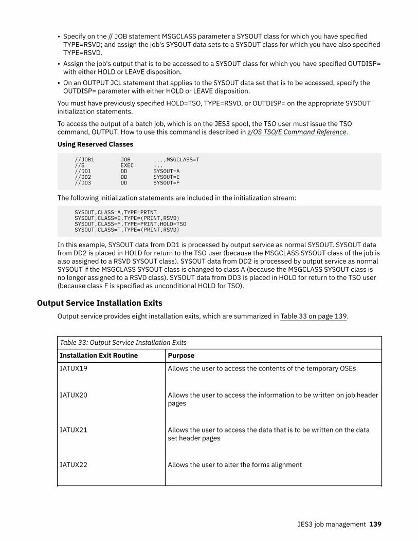
• Specify on the // JOB statement MSGCLASS parameter a SYSOUT class for which you have specifiedTYPE=RSVD; and assign the job's SYSOUT data sets to a SYSOUT class for which you have also specifiedTYPE=RSVD.
• Assign the job's output that is to be accessed to a SYSOUT class for which you have specified OUTDISP=with either HOLD or LEAVE disposition.
• On an OUTPUT JCL statement that applies to the SYSOUT data set that is to be accessed, specify theOUTDISP= parameter with either HOLD or LEAVE disposition.
You must have previously specified HOLD=TSO, TYPE=RSVD, or OUTDISP= on the appropriate SYSOUTinitialization statements.
To access the output of a batch job, which is on the JES3 spool, the TSO user must issue the TSOcommand, OUTPUT. How to use this command is described in z/OS TSO/E Command Reference.
Using Reserved Classes
//JOB1 JOB ...,MSGCLASS=T //S EXEC ... //DD1 DD SYSOUT=A //DD2 DD SYSOUT=E //DD3 DD SYSOUT=F
The following initialization statements are included in the initialization stream:
SYSOUT,CLASS=A,TYPE=PRINT SYSOUT,CLASS=E,TYPE=(PRINT,RSVD) SYSOUT,CLASS=F,TYPE=PRINT,HOLD=TSO SYSOUT,CLASS=T,TYPE=(PRINT,RSVD)
In this example, SYSOUT data from DD1 is processed by output service as normal SYSOUT. SYSOUT datafrom DD2 is placed in HOLD for return to the TSO user (because the MSGCLASS SYSOUT class of the job isalso assigned to a RSVD SYSOUT class). SYSOUT data from DD2 is processed by output service as normalSYSOUT if the MSGCLASS SYSOUT class is changed to class A (because the MSGCLASS SYSOUT class isno longer assigned to a RSVD class). SYSOUT data from DD3 is placed in HOLD for return to the TSO user(because class F is specified as unconditional HOLD for TSO).
Output Service Installation ExitsOutput service provides eight installation exits, which are summarized in Table 33 on page 139.
Table 33: Output Service Installation Exits
Installation Exit Routine Purpose
IATUX19 Allows the user to access the contents of the temporary OSEs
IATUX20 Allows the user to access the information to be written on job headerpages
IATUX21 Allows the user to access the data that is to be written on the dataset header pages
IATUX22 Allows the user to alter the forms alignment
JES3 job management 139

Table 33: Output Service Installation Exits (continued)
Installation Exit Routine Purpose
IATUX23 Allows the user to access the data to be written on the job trailerpages
IATUX39 Allows the user to modify the data set header for a SYSOUT data set
IATUX43 Allows the user to modify a job header for a network streamcontaining SYSOUT data
IATUX45 Allows the user to modify the job information for data sets processedby output writer functional subsystems
The output writer functional subsystem application (FSA) in an output writer FSS includes several non-JES3 installation exits, which are explained in Print Services Facility/MVS System Programmer's Guide. Seethat document for all information on installation exit from the output writer FSA.
PurgePurge is the last processing function for a job in the JES3 system. It releases all JES3 DASD spaceassigned to the job, making it available for allocation to subsequent jobs. A message is issued to theoperator indicating that the job has been purged from the system.
At the conclusion of purge, the JES3 installation accounting routine writes out a type 26 SMF record. Thisrecord contains times and dates of the processing on the processor writing the record. Since the clocks onthe various processors are not synchronized, elapsed times should all be taken from the same types ofrecords (for example, from type 26 records). Otherwise, timing differences in the records may result.
See z/OS MVS System Management Facilities (SMF) for a complete description of record type 26.
140 z/OS: JES3 Initialization and Tuning Guide

Chapter 5. Defining and managing C/I service
Converter/interpreter (C/I) service controls the conversion of JCL statements to Converter/Interpretertext and then control blocks. The three principal phases of C/I service are:
• Converter/interpreter phase: Uses MVS services to convert and interpret the JCL into scheduler controlblocks. At this time, JES3 (through the MVS interpreter) creates the scheduler control blocks in thescheduler work area (SWA) in the JES3 address space on the global main (hereafter called the JES3global address space) or C/I functional subsystem address space(s).
• Prescan phase: Creates job tables from the scheduler control blocks for use in the postscan phase. Atthe end of this phase, JES3 moves the scheduler control blocks from the SWA to the JES3 spool.
• Postscan phase: Locates data sets and gathers information for use in JES3 device setup.
In the JES3 global address space, the CI DSP controls all three of the above phases. More than one copyof the CI DSP can be active at a time. You specify the number of CI DSPs that may be active in the JES3global address using the JES3 STANDARDS initialization statement.
C/I service can also take place in a C/I functional subsystem (FSS) address space. A C/I FSS addressspace contains many functions similar to a JES3 address space and can operate on the global or any localmain. Where the address space operates depends on what you specify for the FSS on its JES3 FSSDEFinitialization statement. You specify the maximum number of CI DSPs that may be active in a C/I FSSaddress space using the JES3 FSSDEF initialization statement defining that address space.
The CI DSPs that run in a C/I FSS address space process jobs through the converter/interpreter andprescan phases of C/I service. JES3 can also perform the catalog search (locate) portion of the postscanphase in a C/I FSS if the main where the CI FSS runs has access to the necessary catalogs.
After a job passes through the converter/interpreter and prescan phases in a C/I FSS address space, C/Iservice returns the job to the JES3 global for the remainder of the postscan phase. There, the job'spostscan processing takes place under a separate POSTSCAN DSP. You specify the number of POSTSCANDSPs that may be active in the JES3 global address space using the JES3 STANDARDS initializationstatement.
“Setting Up C/I Service” on page 141 explains how to set up C/I services to make the best use of theaddress spaces available to JES3.
“Controlling Jobs Through C/I Service” on page 146 briefly describes the installation exit routines andother means available to influence a job's C/I processing.
“Managing the Scheduler Work Area” on page 150 explains how to avoid storage constraints in thescheduler work area (SWA).
“Monitoring and Modifying C/I Service” on page 154 lists the operator commands that you can use tomonitor and change the C/I setup after JES3 initialization.
“Managing Procedure Libraries” on page 156 explains how to update the procedure libraries used by C/Iservice.
Setting Up C/I ServiceJES3 interprets each job's JCL using a separate copy of the CI DSP. For jobs processed in C/I FSS addressspaces or for rescheduled jobs, JCL interpretation occurs in a CI DSP and then in a POSTSCAN DSP. Thus,for every job in C/I service, there is one CI or POSTSCAN DSP allocated to the job. JES3 defines each CIand POSTSCAN DSP to handle either batch or demand select jobs. Demand select jobs are started tasksand TSO LOGON jobs.
To set up C/I service, you must first determine whether to use C/I FSS address spaces and, if so, where toplace them. Then, decide how many CI DSPs to define for each address space in which C/I processing cantake place. Finally, determine how many POSTSCAN DSPs should run in the JES3 global address space.
© Copyright IBM Corp. 1988, 2017 141

Advantages to Using C/I FSS Address SpacesThe primary advantage of using C/I FSS address spaces is to off-load much of the overhead caused byconverter/interpreter processing from the global address space.
C/I service uses large quantities of the scheduler work area (SWA) and storage in subpool 0. BecauseJES3 support of 31-bit addressing relieves virtual storage constraint, an installation may choose toincrease CSA and consequently reduce the size of the JES3 region. In this case, an installation runningmany CI DSPs in the JES3 global address space may encounter private virtual storage constraint. Whenvirtual storage is severely constrained, one of three actions occurs:
• JES3 functions terminate with out-of-storage abend codes (such as 80A)• C/I service fails jobs that would cause out-of-storage abends• Address space JCL statement limit processing causes CI DSPs and jobs to wait
To relieve actual or foreseen private virtual storage constraint in the JES3 global address space, you canestablish C/I FSS address spaces. For every CI DSP you define in the C/I FSS address space, you canreduce by one the number of CI DSPs in the JES3 global address space. This reduction means C/I servicein the JES3 global address space uses less virtual storage. If private virtual storage becomes constrainedin the C/I FSS address space and causes out-of-storage abends, JES3 global address space functions arenot affected.
Another advantage to having C/I FSS address spaces is that you can define more CI DSPs in the JES3complex than the JES3 global address space alone can handle. Thus, C/I service can process more jobs inthe JES3 complex at a time.
C/I FSS address space requirementsThe number of C/I FSS address spaces that your installation requires, if any, depends on virtual storageconstraints in the JES3 global address space. An installation with no virtual storage constraints and noexpected requirement for more CI DSPs requires no C/I FSS address spaces. An installation with severevirtual storage constraints and a heavy work load should set up C/I FSS address spaces. That installationshould also decrease the number of CI DSPs in the JES3 global address space, perhaps eliminating themaltogether. (Remember that postscan processing always takes place in the JES3 global address space,whether under a CI DSP or a POSTSCAN DSP.)
Where should a C/I FSS address space be placed? Placing one on a local processor requires CTCcommunication with the global processor. CTC communication causes more overhead than placing a C/IFSS address space on the global processor. However, placing a C/I FSS address space on the globalprocessor uses processing capability that other JES3 functions that must run on the global processorcould use. Placing C/I FSS address spaces on the global processor, then, reduces performance for jobsbeing processed in the JES3 global address space. Placing C/I FSS address spaces on a local processorreduces performance for jobs being processed by those C/I FSS address spaces.
If you establish C/I FSS address spaces on one or more local processors, you must ensure that they canaccess the same system procedure libraries. To ensure that all CI DSPs use identical procedure libraries,place the procedure libraries on DASD devices that are defined to MVS as shared among all processorseligible for C/I FSS address spaces. Also define the DASD devices as jointly-managed by JES3 and MVS(that is, defined to MVS as permanently resident).
Deciding how many C/I FSS address spaces to define for a particular processor requires additionalcalculation. Each C/I FSS address space requires some space in the common service area (CSA) and thesystem queue area (SQA) for control blocks. (See the following subsection for the space requirements.)The control blocks either reduce the amount of available CSA and SQA or require the installation to definemore SQA, thus reducing the amount of private area virtual storage. Also, C/I FSS address spaces candegrade system performance because they are non-swappable.
Storage management subsystem considerations
If you are using the storage management subsystem (SMS), you should define C/I functional subsystemsonly on mains where SMS is enabled. JES3 will start C/I FSSs only on mains where SMS is active.
142 z/OS: JES3 Initialization and Tuning Guide

Avoiding common storage constraints
The JES3 support for 31-bit addressing provides storage constraint relief for the C/I FSS address spacesbecause much of the JES3 code and many control blocks are above 16 megabytes. However, you may stillwant to examine potential areas of constraint.
Some data areas associated with the C/I FSS address spaces occupy common storage. Factor the amountof common storage occupied by these data areas (given below) into your calculations of how many C/IFSS address spaces to establish on each processor.
• IATYBAL (BALJ) - For every C/I FSS address space active in the processor, there is one BALJ data area inSQA. The BALJ data area occupies 88 bytes plus one byte per page of JSAM buffer space. For example,suppose you specify a 250-page JSAM buffer pool for FSS address spaces. If two C/I FSS addressspaces are active in a given processor, that processor will have two BALJ data areas, each occupying338 bytes of SQA.
• IATYDMC (DMC) - For every data buffer block (DAT) defined in the JSAM buffer pool of every active C/IFSS address space, a data management control block (DMC) occupies 160 bytes of CSA in subpool 231.The DMC data area cannot cross page boundaries, and each C/I FSS address space has its own DMCpool. For example, suppose you specify a JSAM buffer pool size of 250 pages for FSS address spacesand a buffer size of half a page. If two C/I FSS address spaces are active in a given processor, thatprocessor will have 1000 DMC data areas occupying a total of 128K of CSA.
• IATYRAB (RAB) - For every job in the converter/interpreter or prescan phase of C/I service, a recordallocation block (RAB) occupies 112 bytes of CSA.
• IATYDSS (DSS) - For every C/I subtask, there are three data set status blocks (DSSs) in CSA. Each DSSoccupies 328 bytes.
MVS performance considerations
C/I FSS address spaces are not swappable because they use JSAM to perform I/O operations. Non-swappable address spaces occupy central storage at all times and therefore may adversely affect MVSperformance. To avoid adverse effects on MVS performance, tune the number of C/I FSS address spacesafter initialization using operator commands. For a list of those commands, see “Monitoring and ModifyingC/I Service” on page 154.
Using multi-character CLASS names on the JOB card
Starting at level HJS7790, JES3 supports a CLASS name of greater than one character on the JOB card,up to a maximum of eight characters. In a JESPlex with main processors at mixed JES3 levels, the JES3global address space must be at HJS7790, or later, at all times for multi-character CLASS names on theJOB card to function properly.
Furthermore, C/I service on a main processor at HJS7790, or later, must be available within the JESPlexto convert and interpret the JCL. This C/I service can be available from either C/I DSPs configured withinthe JES3 global address space or from a C/I FSS address space, as long as the C/I service runs on a mainprocessor at HJS7790, or later. If this C/I service is unavailable, the jobs wait until the C/I servicebecomes available.
Note: JES3 supports up to eight characters for the CLASS name.
Defining a C/I FSS address spaceIf you decide that establishing C/I FSS address spaces will help your installation, you must supply acataloged procedure for starting the C/I FSS address spaces. Then, define each C/I FSS address spaceyou want to establish using the FSSDEF initialization statement. (You cannot define or add a C/I FSSaddress space using operator commands.) Follow the steps given below.
1. Include a procedure for starting a C/I FSS address space in the appropriate procedure library for yourinstallation. The default C/I FSS start procedure resides in SYS1.SIATSAMP in the members IATJ3CIand JES3CI. The JCL statements included in this procedure are:
//JES3CI EXEC PGM=IATINTKF,DPRTY=(15,14)//STEPLIB DD DSN=SYS1.SIATLIB,DISP=SHR
Defining and managing C/I service 143

//CHKPNT DD DSN=SYS1.JES3CKPT,DISP=SHR//CHKPNT2 DD DSN=SYS1.JES3CKP2,DISP=SHR//JES3OUT DD SYSOUT=A//JES3SNAP DD SYSOUT=A//SYSABEND DD SYSOUT=A//JESABEND DD SYSOUT=A
Using this default procedure as a guide, you can change the data set names and the SYSOUT classes tomeet your installation's needs. Always specify the same checkpoint data set(s) as specified in theJES3 start procedure and share the data set(s).
In order to ensure an adequate region size, you may want to add a REGION= keyword to the EXEC JCLstatement. The JES3CI procedure provided by IBM does not include a REGION= keyword. Do notinclude JCL statements to define procedure libraries in the C/I FSS start procedure. If your JES3 loadlibrary is in the link list, you do not need the STEPLIB DD statement.
2. Include the appropriate FSSDEF statement(s) in your initialization stream, one for every C/I FSSaddress space you want to create.
• Specify TYPE=CI. • The PNAME parameter should give the name of the cataloged procedure that starts C/I FSS address
spaces, which is in the procedure library used for started tasks. • Use the SYSTEM parameter to specify the JES3 processor on which you want to establish the C/I FSS
address space. • Use the START parameter to specify whether you want JES3 to automatically start this C/I FSS
address space when an eligible processor is available and both subparameters of the DSPCNTparameter (see below) do not equal 0.
• Use the DSPCNT parameter to specify the maximum number of CI DSPs that may operate in the C/IFSS address space. Specify this number by giving the maximum number of DSPs for batch jobs or themaximum number of DSPs for demand select jobs that may operate concurrently. See “Specifyingthe Number of CI DSPs in a C/I FSS Address Space” on page 145 for guidelines on setting values forthis parameter.
• Use the MAXASST parameter to specify the maximum number of JCL statements all CI DSPs mayprocess concurrently in this C/I FSS address space. See “Selecting the address space JCL statementlimit” on page 152 for guidelines on setting a value for this parameter.
For more information about coding the FSSDEF initialization statement and its selective parameters,see z/OS JES3 Initialization and Tuning Reference.
Defining the Maximum Number of CI and POSTSCAN DSPsYou can specify the maximum number of CI DSPs that can run in the JES3 global address space using theSTANDARDS initialization statement. You can also specify the maximum number of CI DSPs that can runin a C/I FSS address space using the appropriate FSSDEF initialization statement. To specify themaximum number of POSTSCAN DSPs (which can run only in the JES3 global address space), use theSTANDARDS statement.
The combined maximum number of CI and POSTSCAN DSPs in all address spaces equals the maximumnumber of jobs that C/I service can process at any time. Increasing the number of CI DSPs in any addressspace allows C/I service to process more jobs concurrently in that address space and in the JES3complex.However, a CI DSP in a C/I FSS address space that has finished processing a job is considered “inuse” until a POSTSCAN DSP becomes available. The number of POSTSCAN DSPs, therefore, can limit thenumber of CI DSPs in a C/I FSS address space that are actively processing jobs.
Each CI DSP uses at least 13K of private area virtual storage, in addition to the private area virtual storageoccupied by reentrant modules used by all CI DSPs. To calculate how many CI DSPs you should define foreach address space, you must know two things:
• How much private area virtual storage is available• How much of the private virtual storage is not being occupied by other necessary functions
144 z/OS: JES3 Initialization and Tuning Guide

The following subsections describe how to specify and choose the appropriate maximum number of CIand POSTSCAN DSPs for an address space.
Specifying the Number of CI DSPs in the JES3 Global Address Space
Use the STANDARDS initialization statement to specify the maximum number of copies of the CI DSP thatcan operate in the JES3 global address space at any time. The CICNT parameter defines the maximumnumber of CI DSPs that can process (1) batch and (2) demand select (started task and TSO LOGON) jobs.The combined maximum number of CI DSPs active in the JES3 global address space at any time cannotexceed 255.
If you specify CICNT=(0,0), no CI DSPs will run in the JES3 global address space. If you do not specify theCICNT parameter, JES3 defines 2 C/I DSPs assigned to batch jobs and 1 CI DSP assigned to demandselect jobs.
To determine how many CI DSPs to run in the JES3 global address space, consider how much private areavirtual storage is available in that address space. CI DSPs for demand select jobs use less SWA space thanCI DSPs for batch jobs because demand select jobs normally have fewer JCL statements. If private areavirtual storage is constrained, define demand select CI DSPs but no batch CI DSPs.
Note: If you define C/I FSS address spaces for your installation, JES3 creates a special C/I subtask in theJES3 global address space for starting C/I FSS address spaces; it cannot be used for starting other tasksor TSO LOGONs. This subtask allows a C/I FSS address space to be started even if you specifyCICNT=(0,0) in the initialization stream. The DSP counts for the JES3 global address space do not includethis subtask, but you should account for the subtask when determining how much private area virtualstorage is available.
Specifying the Number of CI DSPs in a C/I FSS Address Space
Use the FSSDEF initialization statement that defines a C/I FSS address space to specify the maximumnumber of CI DSPs that can operate in that C/I FSS address space. The DSPCNT parameter defines themaximum number of CI DSPs that can process (1) batch and (2) demand select (started task and TSOLOGON) jobs.
No more than 255 CI DSPs may be active in a C/I FSS address space at one time. Just as too many CIDSPs in the JES3 global address space can cause private virtual storage constraint, too many CI DSPswithin a given C/I FSS address space can cause private virtual storage constraint. However, if a C/I FSSaddress space fails because it has no more virtual storage available, the JES3 global address space is notaffected.
Avoiding Private Area Virtual Storage Constraint Within a C/I FSS Address Space
To avoid private virtual storage constraint within a C/I FSS address space, you must know how muchstorage C/I service requires. You must also know how much common storage is defined on the processorwhere the C/I FSS address space executes.
The amount of storage required for each C/I FSS support item is listed below. From these numbers, youcan determine how many CI DSPs may run concurrently within a C/I FSS address space withoutconstraining private virtual storage.
• Nucleus support services, those service routines required to execute the C/I routines, require roughly103K of storage in subpool 251. These routines also support the rest of the JES3 functions available inthe C/I FSS address space.
• Resident reentrant modules, required when one or more CI DSPs are active in a C/I FSS address space,occupy approximately 30K of storage in subpool 0. The amount of storage varies depending on the sizeof the installation exit routines.
• Resident CI DSP private area control blocks, required when one or more CI DSPs are active in a C/IFSS address space, occupy about 2K of storage. The exact amount of storage depends on the size of theprocedure library tables and the HWS, CIPARM, and RESDSN tables.
• DSP-specific data areas occupy about 6K of storage for every CI DSP. Data areas used by the CI DSP onbehalf of a job occupy about 50 bytes in subpool 0 and 576 bytes in subpool 236 or 237 for each DDstatement.
Defining and managing C/I service 145

• C/I subtask data areas occupy about 28K of storage in subpool 229 for every C/I subtask.• Control blocks for the C/I subtasks to access the JESJCL, JESJCLIN, and JESYSMSG data sets
require the following storage space for each data set to be accessed:
– IATYDSB (DSB), the data set block: 208 bytes in subpool 230– IATYDSS (DSS), the data set status block: 328 bytes in subpool 241– IEZDEB (DEB), the data extent block: 68 bytes in subpool 0– IATYDAT (DAT), the USAM spool data buffer block: two pages in subpool 229. To determine how
many DATs fit in the two pages, divide 8192 bytes (two pages) by the number of bytes in one buffer,as specified using the BUFSIZE parameter on the BUFFER statement.
– IATYDMC (DMC), the data management control block: 160 bytes in subpool 229 for every DAT (seeabove)
• The RESQUEUE cell pool requires 600 bytes for each CI DSP defined on the FSSDEF statement usingthe DSPCNT parameter (or as modified by the *F,F command), rounded upwards to the nearest page.For example, if the CI DSP count has not been modified and is specified as DSPCNT=(1,2), then thenumber of required bytes would be 3 times 600, or 1800. That number would be rounded upwards to4096 bytes, for one page. The RESQUEUE cell pool is in subpool 6.
• The preallocated FCT entries require 600 bytes for each CI DSP defined on the FSSDEF statementusing the DSPCNT parameter (or as modified by the *F,F command). This value is not rounded upward tothe nearest page. The preallocated FCT entries are in subpool 0.
In sum, a C/I FSS address space contains at least 171K of private area virtual storage for modules anddata areas, plus storage for the JSAM buffer pool and job-related data areas. The functional subsysteminterface (FSI) modules and control blocks occupy about 4K of additional storage.
Specifying the Number of POSTSCAN DSPs
Use the STANDARDS initialization statement to specify the maximum number of POSTSCAN DSPs that canoperate in the JES3 global address space at any time.A POSTSCAN DSP performs postscan processing foreach job processed by a CI DSP in a C/I FSS address space and for each rescheduled job. (Rescheduledjobs include dependent job control (DJC) jobs for which predecessor jobs have not completed.) ThePSTCNT parameter defines the maximum number of POSTSCAN DSPs that can process (1) batch and (2)demand select (started task and TSO LOGON) jobs.
To choose values for the PSTCNT parameter, add the maximum number of batch jobs that each C/I FSSaddress space can process. Then, separately add the maximum number of demand select jobs that eachC/I FSS address space can process. If your installation uses dependent job control (DJC), increase thebatch value to account for rescheduled DJC jobs. You can use these batch and demand select values asthe initial PSTCNT values.
Then, consider the effect of the number of POSTSCAN DSPs on the number of catalog locate requestsbeing processed and the number of catalog volumes set up for postscan processing. Each job and stepcatalog data set for a job causes a setup call for the volume, which may require an operator to mount avolume. A volume mount causes a significant delay in processing. Even if the volume does not needmounting, volume setup and allocation to the job or step catalog library increases processing time. If yourinstallation experiences delays in processing because of jobs waiting for locate processing or catalogvolume setup, reduce the number of POSTSCAN DSPs using the *MODIFY,X command.
Controlling Jobs Through C/I ServiceYou can use installation exit routines to ensure that jobs going through C/I service comply with installationstandards or to approve exceptions. Another way to affect C/I service is to define one or more optionslists for use by the MVS converter. The options lists can specify various job-related requirements anddefault values.
This section describes, in brief, the installation exit routines and initialization statements available to youfor controlling jobs through C/I service.
146 z/OS: JES3 Initialization and Tuning Guide

Controlling Job Flow with Installation ExitsThe installation exit routines available for controlling job flow through C/I service are summarized in Table34 on page 147. Some of these exits are taken during input service, before C/I processing. The inputservice exits influence C/I service by allowing the user to change a job's JCL statement values. The C/Iservice installation exits let you write routines to examine and change the results of C/I processing. Oneinstallation exit (IATUX26) is taken at MVS execution time (after C/I processing) but lets the exit routinemake changes to the results of C/I processing. Installation exits IATUX03 - IATUX09, IATUX11, IATUX26,IATUX28, and IATUX41 let you decide whether to continue processing a job or remove it from the system.For detailed information on the installation exit routines, see z/OS JES3 Customization.
Table 34: Installation Exits for Monitoring JCL Interpretation
Installation ExitRoutine
Purpose
IATUX03 Allows you to access JES3 Converter/Interpreter text created from JCL by the MVSconverter
IATUX04 Allows you to access JOB statement information from scheduler control blocks
IATUX05 Allows you to access EXEC statement information from scheduler control blocks
IATUX06 Allows you to access DD statement and SMF job management record informationfrom scheduler control blocks
IATUX07 Allows you to make a decision on an unsuccessful catalog LOCATE request
IATUX08 Allows you to determine whether a job can use job setup as specified, go throughhigh watermark setup, or should fail
IATUX09 Allows you to access final job status and the job summary table (JST) and jobvolume table (JVT) at the end of interpreter service
IATUX10 Allows you to supply a message when the message number specified on theIATXIWT macro is not in a predefined table
IATUX11 Allows you to inhibit the writing of the LOCATE request/response into a job'sJESYSMSG data set
IATUX26 Allows you to access MVS scheduler control blocks (during job execution) beforethey are moved to the scheduler work area (SWA)
Defining and managing C/I service 147

Table 34: Installation Exits for Monitoring JCL Interpretation (continued)
Installation ExitRoutine
Purpose
IATUX28 Allows you to verify or change information specified on the JOB JCL statement(during input service)
IATUX29 Allows you to change information specified on the JOB JCL statement (during inputservice)
IATUX33 Allows you to verify or change (during input service) EXEC JCL statements or JES3control statements (except //*DATA SET and //*ENDDATASET)
IATUX34 Allows you to verify or change (during input service) DD JCL statements (except DD* or DD DATA statements)
IATUX41 Allows you to cancel a job that contains more JCL statements than allowed by thejob JCL statement limit or to override the job JCL statement limit
IATUX44 Allows you to change any JCL statements other than the JOB, EXEC, and DDstatements (during input service)
IATUX46 Allows you to select the processors where the conversion and interpretation of ajob's JCL can take place and specify whether the JES3 global address space can beused, if you have defined C/I FSS address spaces
IATUX49 Allows you to override JES3's selection of an address space for C/I processing of ajob's JCL, if you have defined C/I FSS address spaces
Assigning jobs to the appropriate processor and address space for C/I serviceIf you have defined C/I FSS address spaces, two installation exits let you control where jobs getprocessed through C/I service. If you have defined C/I FSS address spaces on local processors,remember that C/I processing of jobs might take place on a local processor. Also, remember that in acomplex having processors with different release levels of MVS or different JCL definitions, jobs may useJCL parameters or statements that require conversion, interpretation, and execution on a particularsystem. You must ensure that JES3 routes those jobs to the proper system.
Before the job enters C/I processing, you can use installation exit IATUX46 to examine and limit theprocessors eligible for selection for the job's C/I processing. You can also specify whether the JES3 globaladdress space is eligible. You can use installation exit IATUX49 to override JES3's choice of addressspace (and, thus, the processor) for the job's C/I processing. For detailed information on the installationexit routines, see z/OS JES3 Customization.
You may also influence JES3's decision as to where to schedule C/I processing by the CIDEMAND (fordemand select jobs) and CIBATCH (for batch jobs) initialization parameters on the CLASS or STANDARDSinitialization statements. You may use these parameters to indicate that jobs of a certain class or all jobsmust have C/I processing performed where the job's class is enabled or where the job is eligible to run.
148 z/OS: JES3 Initialization and Tuning Guide

Within the limits imposed by installation exits IATUX46, IATUX49, and the CIDEMAND and CIBATCHinitialization parameters, JES3 schedules jobs to a CI DSP using a priority scheme that considers whetherjobs are batch or demand select jobs.
JES3 schedules demand select jobs to demand select CI DSPs in the following priority:
1. In the JES3 global address space.2. In any C/I FSS on the global, provided that the job can execute on the global.3. In any C/I FSS on a local, provided that the job can execute on the selected local.4. In any C/I FSS on the global, regardless of whether the job can execute on the global.5. In any C/I FSS on a local, regardless of whether the job can execute on the selected local.
Note: If more than one C/I FSS is active, JES3 selects the FSS with the greatest number of availabledemand select CI DSPs.
JES3 attempts to schedule batch jobs to batch CI DSPs in the following priority:
1. In any C/I FSS on the global, provided that the job can execute on the global.2. In any C/I FSS on a local, provided that the job can execute on the selected local.3. In any C/I FSS on the global, regardless of whether the job can execute on the global.4. In any C/I FSS on a local, regardless of whether the job can execute on the selected local.5. In the JES3 global address space.
Note:
1. If more than one C/I FSS is active, JES3 selects the FSS with the greatest number of available batch CIDSPs.
2. Either the SYSTEM or SYSAFF parameter on the JOB control statement, or the SYSTEM parameter onthe //*MAIN control statement, is considered for CI scheduling purposes when determining where thejob is eligible to run. The job's scheduling environment does not apply.
Using system symbols in source JCL for demand select jobsJES3 allows you to specify system symbols in source JCL for demand select jobs. System symbols allowtwo or more systems in a JES3 complex to share the source JCL, while retaining unique values in the JCL.
System symbols represent unique values in source JCL for demand select jobs. Each system has its ownvalues for system symbols. When shared demand select jobs are processed, each JES3 system replacesthe system symbols with its own values.
When the source JCL for a demand select job is sent to another processor for conversion (see the sectionthat describes the converter/interpreter phase in Chapter 5, “Defining and managing C/I service,” on page141), the converter uses the system symbols that are defined to the processor on which the started taskwas submitted (not the processor on which the conversion takes place).
JES3 updates the system symbols table each time the system connects to the JES3 global, including eachinstance of the JES3 global connecting to itself. You can therefore update system symbols by running theJES3 *S main,CONNECT command. If you update system symbols using the SETLOAD IEASYM command,you can use these updated symbols for future conversions by running the *S main,CONNECT command,where main is the name of the updated system. This system symbols update will not affect jobs that havealready undergone conversion.
For more information about system symbols, refer to the following documentation:
• z/OS MVS Initialization and Tuning Reference for details about planning to use system symbols• z/OS MVS JCL Reference for information about using system symbols in JCL• z/OS MVS System Commands for information about the SETLOAD IEASYM command• z/OS JES3 Commands for information about using system symbols in JES3 commands.
Defining and managing C/I service 149

Defining a converter/interpreter options listThe MVS converter/interpreter runs under a C/I subtask during the converter/interpreter phase of C/Iservice. You can define one or more options lists for use by the MVS converter/interpreter. The options listprovides installation defaults for certain JCL keywords. Each options list can specify:
• Whether a JOB statement must specify a programmer name or an account number, or whether thescheduler work area is located above 16-megabytes when a job executes
• The maximum execution time for a job step• The default region size for a job step• Whether MVS is to bypass label processing• Whether the MVS C/I routines are to write the following information to the system message data set:
– JOB statement– Input JCL (including in-stream procedures)
• Whether the MVS allocation routines are to write allocation/termination messages to the systemmessage data set
• The message class default
To define and name an options list, code a CIPARM initialization statement. Use the PARMID= parameteron this statement to name the list. You must code a separate CIPARM statement for each options list. Seethe CIPARM statement in z/OS JES3 Initialization and Tuning Reference for information on the defaultoptions used for a job submitted to a node through NJE.
Each time the operator calls a disk reader, a card reader, or a tape reader, the operator can select one ofthe options lists that you defined. Thereafter, each time the MVS C/I routines process a job read from thatparticular reader, the MVS C/I routines use the selected options list.
To call a reader and select an options list, the operator must issue one of the following commands:
• *CALL,CR,...PARMID=xx• *CALL,DR,...PARMID=xx• *CALL,TR,...PARMID=xx
The variable xx is the name of the options list the operator wants to select. This must be the same nameyou used when you defined the options list.
To specify which options list the MVS C/I routines should use for internal reader jobs, started tasks, andTSO LOGON jobs, use the INTPMID, STCPMID, and TSOPMID parameters on the STANDARDS initializationstatement.
Managing the Scheduler Work AreaThe scheduler work area (SWA) of the JES3 global address space or the C/I FSS address space serves asstorage for the scheduler control blocks derived from a job's JCL statements during the converter/interpreter phase. At any time, the SWA contains the scheduler control blocks for all jobs that CI DSPs areprocessing at that time, from the converter/interpreter phase through the prescan phase. When a CI DSPfinishes processing a job, JES3 or the C/I FSS writes that job's scheduler control blocks to the spool. JES3or the C/I FSS then frees the SWA space occupied by that job's scheduler control blocks.
If a CI DSP starts to process a job but there is not enough SWA space to store the job's scheduler controlblocks, C/I service cancels the job, or JES3 or the C/I FSS address space processing the job mayterminate abnormally.
There are two reasons why there might not be enough space in the SWA for a job's scheduler controlblocks.
150 z/OS: JES3 Initialization and Tuning Guide

• The job itself contains so many JCL statements that the control blocks derived from the JCL will not fitin the SWA.
• JCL statements from other jobs that CI DSPs are processing concurrently have caused scheduler controlblocks to temporarily fill most or all of the SWA. A single large job (that is, a job with many JCLstatements) or many smaller jobs that CI DSPs are processing could cause this condition.
You can limit the amount of SWA space generally used by C/I service in three ways:
• Balance the C/I service work load among the JES3 global address space and C/I FSS address spaces sothat no one address space requires more SWA space than it has available.
• Limit the number of JCL statements allowed for each job, thus preventing a large job from dominatingthe SWA.
• Limit the number of JCL statements that can be processed by the JES3 global address space or a C/IFSS address space at any time. This limit prevents the address space from running out of SWA spaceand abnormally terminating.
For further information about balancing the work load, see “Setting Up C/I Service” on page 141.
Creating SWA SpaceSWA space is created twice for each job. It is first created during C/I processing in the global addressspace or in the C/I FSS address space. This initially-created SWA space is always located above 16-megabytes.
Although you need not be concerned with storage constraint in expanded storage, you can still specify alimit on the number of address space JCL statements that can be processed concurrently. The addressspace JCL statement limit indicates the number of JCL statements that all CI DSPs in a given addressspace may process concurrently. See “Preventing a Job from Dominating the SWA” on page 151 for moreinformation.
The second time SWA space is created is when the job executes. For job execution, SWA space is locatedin the private area of the job's address space above or below 16-megabytes. To control which jobs willhave SWA space created in expanded storage, use the CIPARM initialization statement.
Because jobs with a large number of JCL statements can cause storage constraint problems, you maywant to specify a job JCL statement limit. The job JCL statement limit indicates the number of JCLstatements a job may have and continue into MVS interpretation. See the following topic, “Preventing aJob from Dominating the SWA” for further information.
Preventing a Job from Dominating the SWATo prevent a job with many JCL statements from dominating the SWA, use the job JCL statement limit. If ajob contains more JCL statements than the job JCL statement limit allows and you have not provided anexit routine for installation exit IATUX41, JES3 cancels the job. If you provide the exit routine, JES3 allowsthe exit routine to decide whether to cancel the job or to let the job continue.
Selecting the Job JCL Statement Limit
To select the job JCL statement limit, determine the number of JCL statements that are in the largest jobyou want to run at your installation. Specify that number on the MAXJOBST= parameter of theSTANDARDS initialization statement. The next time you do a hot start with refresh, warm start, or coldstart using the initialization stream containing that STANDARDS statement, JES3 uses the job JCLstatement limit you specified.
You can override the effects of this limit on a particular job by writing an exit routine for installation exitIATUX41. This installation exits lets you decide whether a job that exceeds the job JCL statement limitshould continue processing. To find out how to write an exit routine for installation exit IATUX41, see z/OSJES3 Customization.
To set or change the job JCL statement limit without restarting JES3, issue the *F,X,D=CI,MAXJOBST=nnncommand. This command becomes effective for the next job to enter C/I processing and remains in effect
Defining and managing C/I service 151

across a hot start. To display the current value of the job JCL statement limit, issue the *I,X,D=CIcommand.
If the initialization stream does not specify a job JCL statement limit, JES3 uses the default value of 0.When the job JCL statement limit is 0, there is no limit on the number of allowable JCL statements. JES3does not check to see if jobs have too many JCL statements to fit in the SWA.
Preventing Abnormal Termination of JES3 or a C/I FSS Address SpaceTo prevent abnormal termination of the JES3 global address space or a C/I FSS address space when thereis not enough SWA space to store the scheduler control blocks derived from a job's JCL, specify anaddress space JCL statement limit. The address space JCL statement limit defines the maximum numberof JCL statements that all CI DSPs in an address space can process concurrently.
For the JES3 global address space, specify the address space JCL statement limit using the MAXASSTparameter on the STANDARDS initialization statement or the MAXASST= operand on the *F,X,D=CIoperator command. For a C/I FSS address space, specify the address space JCL statement limit using theMAXASST parameter on the FSSDEF initialization statement or using the MAST= operand on the *F,Foperator command.
Note: The address space JCL statement limit and the job JCL statement limit do not affect demand select(started task and TSO LOGON) jobs. This means that:
• A demand select job can contain more JCL statements than either JCL statement limit allows.• When counting the total number of JCL statements that all CI DSPs are processing, JES3 does not count
the JCL statements for demand select jobs.
However, demand select jobs generally use few JCL statements. Most installations will not encountervirtual storage constraint while converting or interpreting demand select jobs.
After you set the address space JCL statement limit(s), JES3 allows a CI DSP to process a job only if bothof the following are true:
1. The number of JCL statements for the job is less than the address space JCL statement limit2. The sum of the number of JCL statements for the job plus the number of JCL statements all CI DSPs
are processing at that time in the address space is less than the address space JCL statement limit
If the first condition is not true, JES3 cancels the job. If the second condition is not true, JES3 makes thejob wait. In addition, all jobs that have not yet begun MVS converter processing wait, while jobs that areinto or past MVS interpretation continue processing.
After JES3 writes a job's JCL (as scheduler control blocks) to the spool, JES3 frees the SWA space. Thetotal number of JCL statements that all CI DSPs are processing in the address space decreases by thenumber of JCL statements in the job. When this total decreases to a point where the waiting jobs can beprocessed without exceeding the address space JCL statement limit, JES3 allows the jobs to continueprocessing.
Selecting the address space JCL statement limit
Table 35 on page 152 describes a procedure for selecting and setting the address space JCL statementlimit. The left column of the figure explains each step of the procedure; the right column shows anexample of the procedure. The example shows how to use the procedure.
Table 35: Procedure for Selecting and setting an address space JCL statement limit.
Procedure Example Example
1. Determine how much space is available inprivate virtual storage for SWA space to storescheduler control blocks derived from thejob's JCL statements.
Assume there are 60000 bytes available.
152 z/OS: JES3 Initialization and Tuning Guide

Table 35: Procedure for Selecting and setting an address space JCL statement limit. (continued)
Procedure Example Example
2. Divide the amount of available SWA space by600. (600 is the average number of bytes ofstorage needed for one JCL statement. (SeeNote 1.)
The quotient represents the maximumnumber of JCL statements whose schedulercontrol blocks can be stored in the SWA atone time.
Ignore the remainder.
• 60000/600 = 100 with a remainder of 0• 100 JCL statements can be stored in
scheduler control blocks in the SWA at onetime
3. To set (or change) the address space JCLstatement limit using the initialization stream:
• For the JES3 global address space, code theparameter MAXASST=nnn on theSTANDARDS initialization statement.
• For a C/I FSS address space, code theparameter MAXASST=nnn on the FSSDEFinitialization statement.
(See Note 2.)
Restart JES3 with a warm start or hot startwith refresh.
STANDARDS,MAXASST=100,...
FSSDEF,TYPE=CI,FSSNAME=fssname,MAXASST=100,...
4. To set (or change) the address space JCLstatement limit without restarting JES3:
• For the JES3 global address space, issuethe command *F,X,D=CI,MAXASST=100
• For a C/I FSS address space, issue thecommand *F,F,FSS=fssname,MAST=100
(See Note 2.)
*F,X,D=CI,MAXASST=nnn.
*F,F,FSS=fssname,MAST=nnn.
Note:
1. Each DD statement generates an SIOT (192 Bytes), a JFCB (192 Bytes), and almost always a JFCBX (192Bytes). This gives 576 total bytes. Add to that a ‘share’ of the STEP and JOB related control blocks and youget at least 600 bytes required per DD statement.
2. Substitute the value you got in step 2 for nnn.
If you change an address space JCL statement limit, the change remains in effect across a hot start.
If the initialization stream does not specify an address space JCL statement limit, JES3 uses the defaultvalue of 0. The default value of 0 means the number of JCL statements for the address space has no limit.In this case, JES3 does not prevent a CI DSP from processing a job even though there is not enough SWAspace for the job's scheduler control blocks. If there is not enough SWA space, the address spaceprocessing the job will abnormally terminate or the job will be canceled by the MVS interpreter.
To display the current value of the address space JCL statement limit in the JES3 global address space,issue the command *I,X,D=CI. To display the current value of the address space JCL statement limit for aC/I FSS address space, issue the command *I,F,FSS=fssname.
Defining and managing C/I service 153

Monitoring and Modifying C/I ServiceAfter you have set up C/I service for your installation, you may need information about jobs in C/Iprocessing or about the CI DSPs themselves. You might use such information to judge how well C/Iservice meets the installation's needs and the needs of individual jobs. If any problems become evident,you might also need to change the C/I service setup. The sections below briefly list the operatorcommands that let you monitor and change C/I service.
For details about the particular commands and operands, see z/OS JES3 Commands.
Determining the Status of C/I ServiceThe *INQUIRY command lets you display the status of jobs and the status of CI DSPs, as described below.
Displaying the Status of Jobs
Use the *INQUIRY (*I) command to learn what phase of C/I processing a job or jobs are in and which C/IFSS address space (if any) is processing the job.
• For a specific job:
*I,J=jobname|jobno|jj*• For jobs of a specific priority:
*I,P=prty,N=nnn|ALL• For jobs in the job queue:
*I,Q,J=jobno,N=nnn|ALL
Displaying the Status of CI and POSTSCAN DSPs
Use the *INQUIRY command to display information about the status of CI and POSTSCAN DSPs.
• For jobs waiting to be scheduled for a CI DSP:
*I,Q,D=CI• For information on why jobs are not being scheduled for the CI DSP and how long they are waiting:
*I,Q,D=CI,W• For jobs currently being processed by CI DSPs:
*I,A,D=CI• For the status (held or released) of C/I scheduling:
*I,X,D=CI• For jobs waiting to be scheduled for a POSTSCAN DSP:
*I,Q,D=POSTSCAN• For jobs having a scheduling environment in a particular priority and waiting to be scheduled
*I,P=12,W• For jobs currently being processed by POSTSCAN DSPs:
*I,A,D=POSTSCAN• For information on why jobs are not being scheduled for the POSTSCAN DSP and how long they are
waiting.
*I,Q,D=POSTSCAN,W• For the complex-wide job JCL statement limit and the JES3 global address space JCL statement limit for
CI DSPs:
*I,X,D=CI
154 z/OS: JES3 Initialization and Tuning Guide

• For the maximum CI DSP count and use count for the JES3 global address space:
*I,X,D=CI• For the maximum DSP count and the address space JCL statement limit for a C/I FSS address space:
*I,F,FSS=fssname
Modifying C/I ServiceAfter you have set up C/I service, you can change the configuration without restarting JES3 by usingoperator commands.
• To stop (HOLD) or resume (RELEASE) scheduling jobs for C/I processing throughout the complex:
*F,X,D=CI,HOLD|RELEASE• To change the number of batch and demand select CI DSPs in the JES3 global address space:
*F,X,D=CI,MC=(maxbatch,maxdemsel)
(This command works even if you specified no CI DSPs on the CICNT parameter of the STANDARDSinitialization statement.)
• To change the number of batch and demand select CI DSPs in the specified C/I FSS address space:
*F,F,FSS=fssname,DSPC=(maxbatch,maxdemsel)
Note: If you specify DSPC=(0,0) on the above command, the C/I FSS address space will not be startedor terminates after all work completes.
• To change the maximum number of JCL statements that all the CI DSPs in the JES3 global addressspace may process concurrently:
*F,X,D=CI,MAXASST=nn• To change the maximum number of JCL statements that all the CI DSPs in the specified C/I FSS address
space may process concurrently:
*F,F,FSS=fssname,MAST=nn• To change the maximum number of JCL statements a job may have before C/I processing fails the job:
*F,X,D=CI,MAXJOBST=nn• To change the maximum number of batch and demand select POSTSCAN DSPs that may operate
concurrently in the JES3 global address space:
*F,X,D=POSTSCAN,MC=(maxbatch,maxdemsel)• To change whether JES3 automatically starts the C/I FSS address space or to restart a C/I FSS that has
terminated:
*F,F,FSS=fssname,ST=Y|N
Note: This change of the C/I FSS address space's characteristics carries over a hot start but not a warmstart. Change is not remembered across a hot start with refresh (unless the FSS is currently active).Also, JES3 starts the address space automatically only if the DSPCNT parameter value is not 0.
• To cancel a job in C/I service:
*F,J=jobno,C|CP or *C,J=jobno• To activate C/I debug processing while the job is in the queue:
*F,J=nnnn,CIDEBUG• To reduce the number of C/I FSS address spaces on a given processor, change the C/I FSS address
space DSP counts to zero using the *MODIFY command, or cancel the C/I FSS address space using theMVS CANCEL operator command.
• To fail a C/I FSS, the C/I driver, or the CI DSP that is processing a job, use the *FAIL command.
Defining and managing C/I service 155

You cannot add a C/I FSS address space using operator commands. You must add a FSSDEF statementdefining the C/I FSS address space to the initialization stream and perform a hot start with refresh orwarm start.
Managing Procedure LibrariesProcedure libraries are partitioned data sets used to hold pre-defined sets of JCL statements calledprocedures. You can specify those procedures by name in EXEC JCL statements. A procedure library canbe one partitioned data set or several partitioned data sets concatenated together. A partitioned data setcan be a member of more than one procedure library.
The user identifies a partitioned data set as a member of a procedure library using a ddname of IATPLBxxor PROCxx on either:
• a DD JCL statement in the JES3 start procedure (see Chapter 2, “Initializing JES3,” on page 3) • the DYNALLOC initialization statement
The last two characters of IATPLBxx ddnames are called the procedure library id (procid).
The user must define a standard, or default, procedure library with the ddname IATPLBST. The IBM-supplied start procedure defines the standard procedure library as including the partitioned data setSYS1.PROCLIB. SYS1.PROCLIB contains IBM-supplied procedures, to which the user can add procedures.The user can also change the standard procedure library to a procedure library of the user's choosing.
When a job requires a procedure in a procedure library, the library that is searched can be specified inseveral ways:
• The library can be specified by ddname on the PROCLIB parameter of a JCLLIB statement. This methodoverrides the job's default library and any library specified by a //*MAIN statement, if present.
• The library can be specified by procid on the PROC parameter of a //*MAIN statement. The procid isappended to IATPLB and the result is used as the library's ddname. This method overrides the job'sdefault library.
• The default library appropriate to the job type, as specified by procid on the STANDARDS initializationstatement (the INTPROC, STRCPROC, or TSOPROC parameter). The default for batch jobs is thestandard procedure library, IATPLBST. If the job does not use any procedures (even if specified on theJCLLIB or //*MAIN statements), JES3 does not assign a default procedure library to the job.
If you have C/I FSS address spaces on local processors, they need access to all procedure libraries. Toensure that all CI DSPs use identical procedure libraries, place the procedure libraries on DASD devicesshared among all processors eligible for C/I FSS address spaces. The DASD devices must also be jointly-managed by JES3 and MVS (that is, defined to MVS as permanently resident or reserved).
The procedure libraries must be cataloged in the MVS catalogs for all processors sharing access if you areusing C/I FSSs. You must also catalog procedure libraries if you plan to use the JES3 procedure libraryupdate facility. See “Updating Procedure Libraries” on page 156 for information about how to updateprocedure libraries.
Note: Converter/Interpreter functional subsystems (C/I FSS) and the PROCLIB update function will obtainunit and volume information for the procedure libraries from the catalog. For these functions, JES3ignores unit and volume information that you specify in the JES3 start-up procedure or on a DYNALLOCinitialization statement.
Updating Procedure LibrariesIf you want to update one or more procedure libraries, you must ensure the integrity of the procedurelibraries by letting JES3 know which data set(s) your job will update. List the names of the data set(s) tobe updated on the UPDATE parameter of the //*MAIN JES3 control statement for that job. Before the jobenters setup processing, JES3 disables all procedure libraries containing those data sets. JES3 and theC/I FSS address spaces, if any, deallocate the procedure libraries so that C/I service cannot use them.
156 z/OS: JES3 Initialization and Tuning Guide

However, another job can update those procedure libraries if the job updates different data sets in thelibrary concatenation.
The procedure libraries remain inaccessible (disabled) to C/I service until the updating job(s) finishexecuting. Other jobs needing those procedure libraries for C/I service must wait. To avoid making otherjobs wait for long periods, keep updating jobs brief, with simple setup requirements. Jobs using otherprocedure libraries are not affected.
When the updating job(s) finish executing, JES3 reallocates the procedure libraries to JES3 and the C/IFSS address spaces. JES3 enables the procedure libraries when no more data sets in the procedurelibraries are being updated.
If a job updating a procedure library is placed in spool hold over a restart, the procedure library remainsdisabled until the job is released from hold and all the processing described above finishes.
If a job updating a procedure library moves any procedure library data set to another volume, the job mustupdate the catalog entry for that data set on all processors having C/I FSS address spaces. Otherwise, C/Iservice cannot find the correct catalog entry to enable the procedure libraries after the job finishesexecuting. When the procedure libraries are enabled, JES3 updates or verifies other information about theupdated procedure library, such as the block size.
Attention: If a job that updates a procedure library is in a JES-managed job class group, and it isupdating the procedure library used to start initiators, make sure that there is at least one initiatorstarted before allowing the job to enter the system. Otherwise, a deadlock will occur; theprocedure library used to start the initiator is disabled, the job is waiting for an initiator, and theinitiator is waiting for the procedure library to be enabled. If this situation arises, the updating jobmust be canceled and resubmitted or a *RESTART,SETUP,jobno,CI command can be used toenable the procedure libraries (and let the initiator start) and restart the job through C/Iprocessing. If a C/I FSS was active on a system that is no longer operational, enter the *Smain,FLUSH command for that system. The command indicates that the C/I FSS is no longeractive, so JES3 can immediately schedule the update job.
If a job that updates a procedure library is in a WLM-managed job class group, it is not necessary to checkwhether there is an initiator started before submitting the job. WLM-managed initiators are not startedunder JES3 and are not affected when a procedure library is disabled.
To prevent new jobs from updating the procedure library, change the DISABLE DSP maximum use countto 0 or issue the *F,X,D=DISABLE,HOLD command. To resume updating, increase the DSP maximumuse count or issue the *F,X,D=DISABLE,RELEASE command.
Note: If you use the proclib update facility to move a procedure library to another volume, and theprocedure libraries are allocated through the JCL statements in the JES3 cataloged start procedure, TheJES3 local address spaces must be restarted in order to:
1. Reallocate the procedure library on the new volume. This is necessary if a JES3 local processor is aDSI candidate. Before a DSI is performed, all locals, which are DSI candidates must be restarted inorder to pick up the change.
2. Vary offline the volume containing the old procedure library. During proclib update processing, theJES3 global and C/I FSS address spaces unallocate the procedure libraries being updated. However,the JES3 local address spaces do not unallocate the proclibs during proclib processing. This causesthe VARY command for the proclib to fail when you attempt to vary the proclib offline to one of thelocal processors.
The JES3 local address spaces do not have to be restarted if the procedure libraries are defined throughthe DYNALLOC statements in the initialization stream.
Displaying the Status of Procedure Library Data SetsYou can display the status of the procedure libraries using the *I,PROCLIB[,ID=procid][,DDNAME=ddname] command. This command shows whether a procedure library concatenation isenabled or disabled and shows the individual data set names in the procedure library concatenation withthe job number and job name of the job updating each data set (if any). If you specify the procedure
Defining and managing C/I service 157

library id (procid) or ddname, the command displays this information only for the specified procedurelibrary.
158 z/OS: JES3 Initialization and Tuning Guide

Chapter 6. Defining and Managing Spool Data Sets
Before initializing JES3, decide how many spool data sets you should allocate and then allocate them.During initialization, format any unformatted spool data sets. You can also define spool space allocationunits suited to the type of work handled by your JES3 complex. Then, define how many of these allocationunits are to be allocated (on each request) to jobs that use a particular processor, job class, or SYSOUTclass.
Optionally, you can define spool partitions, which are logical groups of spool data sets. Further, you canspecify the spool partitions JES3 is to use for each processor, for each job class, and for each SYSOUTclass.
To adjust the spool configuration in your JES3 complex as the installation's work load and other needschange, you can:
• Balance the work load across spool partitions using operator commands• Free spool space either permanently or temporarily, using JES3 operator commands and the dump job
facility• Add or delete spool data sets• Keep track of I/O errors on a spool data set using operator commands and BADTRACK statements• Temporarily remove or permanently replace a spool data set having permanent I/O errors
Defining Spool Data SetsDefining spool data sets requires:
• Determining how many data sets you should allocate• Determining where to allocate a spool data set• Allocating spool data sets• Formatting spool data sets
This section includes guidelines and procedures for these tasks.
Determining How Many Spool Data Sets You Should AllocateSeveral factors determine the number and size of spool data sets that you should allocate:
• The amount of spool space that all jobs in the complex may need at any one time. Allocate enough spoolspace to handle peak usage.
• The number of processors in the complex competing for available control units and devices. The moreprocessors competing for control units and devices, the more spool data sets needed for reasonableperformance. A spool data set should not be busy more than 30 to 40 percent of the time or there willbe too much contention for the data set.
• The type of work being carried out in the complex. Jobs that include large amounts of output handled byJES3 need more spool space than jobs with little output, such as TSO jobs.
• The number of spool partitions in the complex. Each active partition must include at least one spooldata set. Spool partitions cannot share spool data sets.
You cannot allocate more than 1024 spool data sets.
After you initially allocate a number of spool data sets, you may need to adjust that number as theinstallation's work load changes. See “Managing Spool Space” on page 173 to learn how to adjust thenumber of spool data sets.
© Copyright IBM Corp. 1988, 2017 159

Allocating Spool Data SetsTo allocate a spool data set, include a DD statement for the data set in the JES3 start procedure. Todynamically allocate the spool data set, omit the DD statement and include a DYNALLOC statement forthe data set in the JES3 initialization stream. Dynamic allocation provides an easier method for changingyour spool configuration than allocating the spool data sets through the JES3 start procedure with DDstatements.
You can allocate a spool data set on any direct access storage device (DASD). The volume on which aspool data set is allocated must be accessible to the global processor and to all local processors. Eachspool data set must be contained in a single extent. (A single extent is one adjoining group of tracks orcylinders.) You cannot allocate any secondary extents.
A spool data set can be greater than 65,535 tracks only if you specify the DSNTYPE=LARGE keyword onthe JCL DD statement that is used to create the data set.
Creating or using a large format data set requires z/OS V1R7 or later releases. The large format data setcannot be opened on earlier-level systems.
A spool data set can be created with extended attributes so that it is EAS-eligible; then the spool date setcan exist in the Extended Addressing Space (EAS) of an Extended Address Volume (EAV). A spool data setcan be EAS-eligible only if you specify the EATTR=OPT keyword on the JCL DD statement used to createthe data set.
Creating or using a data set with extended attributes requires z/OS V1R12 or later releases. A data setwith extended attributes and residing in the EAS cannot be opened on earlier-level systems.
To avoid degradation of JES3 performance and possible lockouts, do not allocate more than one spooldata set per volume. When a volume contains more than one spool data set, the average seek time toaccess the data increases. Similarly, do not allocate data sets to a volume that JES3 rarely accesses.
Note: This suggestion does not apply to parallel access devices such as ESS. With the parallel accessdevices, a spool data set is not allocated on a single physical device but on a logical device locatedanywhere in the storage cluster.
JES3 spool data sets are location-dependent and unmovable. Utility programs that defragment should notbe allowed to move these data sets. Spool data sets can be marked unmovable by coding DSORG=PSU onthe DCB parameter of the DD statement.
Formatting Spool Data SetsBefore JES3 can use a spool data set, you must format the spool data set by using one of the followingways:
• Format it during JES3 initialization by including a FORMAT statement in the JES3 initialization stream.• Format it by executing the utility program IEBDG as a batch job. This fills the extent with hexadecimal
“FF” data.
If you format a spool data set during JES3 initialization, JES3 can use the spool data set after initializationis completed. If you use IEBDG to format a spool data set, you must then add a TRACK statement to theextent in the initialization stream and run the *MODIFY CONFIG command or use a hot start with refresh,warm start or cold start so that JES3 can use the data set.
Unless you take special action, each spool data set will be limited to 65535 tracks, which is about 3.2 GB.That is the maximum size of a basic format sequential data set. You can use a large format data set tocreate a larger spool data set with greater than 65535 tracks. To get a larger spool data set, use one of thefollowing ways:
• Use an SMS data class for the data set that selects a DSNTYPE value of LARGE. The data set does nothave to be SMS-managed.
• Code DSNTYPE=LARGE on the JCL DD statement that is used to create the data set.
Creating or using a large format data set requires z/OS V1R7 or later. The large format data set cannot beopened on earlier-level systems.
160 z/OS: JES3 Initialization and Tuning Guide

Unless you take special action, each spool data set will not have extended attributes and will not be EAS-eligible. To create a data set with extended attributes that is EAS-eligible, code the EATTR=OPT keywordon the JCL DD statement that is used to create the data set.
Creating or using a data set with extended attributes requires z/OS V1R12 or later. A data set withextended attributes and residing in the EAS cannot be opened on earlier-level systems.
Formatting During JES3 Initialization
To format a spool data set during JES3 initialization, include a FORMAT statement for the spool data set inthe JES3 initialization stream. Then start JES3 using that initialization stream.
The type of start you use depends on why you are formatting the spool data set:
• If you have changed the BUFSIZE= parameter on the BUFFER statement, use a cold start (C). (In thiscase, you must format all spool data sets.)
• If you are replacing a spool data set, use a warm start to replace a spool data set (WR). If you also wantan analysis of the jobs in the job queue, use a warm start with analysis to replace a spool data set(WAR).
• If you are adding a spool data set, run the *MODIFY CONFIG command or use a hot start with refresh(HR), a warm start (W) or a warm start with analysis (WA).
See z/OS JES3 Commands for a discussion of each of these methods of starting JES3.
After JES3 processes the initialization stream, replace the FORMAT statement with a TRACK statement. Ifthe FORMAT statement contained the STT or STTL parameter, also code this parameter on the TRACKstatement.
If you use a warm start and the initialization stream contains a FORMAT statement for a spool data setthat is already formatted, JES3 issues a warning message. JES3 continues with initialization, however,and does not reformat the spool data set.
Formatting with IEBDG
You can use the utility program IEBDG to format a data set that you plan to use as a spool data set. z/OSDFSMSdfp Utilities explains how to use IEBDG. Figure 20 on page 161 shows a sample job that usesIEBDG to format a spool data set.
//JOB1 JOB ..... //FORMAT EXEC PGM=IEBDG //SPXTNT DD DSN=spool data set name,DISP=OLD, // UNIT=SYSDA,VOL=SER=serial number, // DCB=(RECFM=U,BLKSIZE=nnn) //SYSPRINT DD SYSOUT=A //SYSIN DD * DSD OUTPUT=(SPXTNT) FD NAME=SPOOL,FILL=X'FF',LENGTH=nnn CREATE NAME=(SPOOL),QUANTITY=2000000000 END /*
Figure 20: Sample Job Using IEBDG to Format a Spool Data Set
The value of the variable nnn must equal the value of the BUFSIZE= parameter on the BUFFERinitialization statement. The variable nnn appears on both the SPXTNT DD statement and on the FD utilityprogram control statement.
The value of the QUANTITY= parameter on the CREATE statement determines how much of the spooldata set IEBDG formats. To ensure that IEBDG formats the entire data set, specifyQUANTITY=2000000000.
If IEBDG successfully formats the entire spool data set, the formatting job ends with an abend code ofD37. In addition, MVS issues message IEC031I. Ignore the corrective action specified in the message.
Defining and Managing Spool Data Sets 161

The formatting job abnormally terminates because the value of the QUANTITY= parameter causes IEBDGto try to format more records than the data set can contain.
If the job ends without the D37 abend code and the message, IEBDG may not have formatted the entirespool data set. Do not use the spool data set. Instead, find the problem, fix it, and then rerun IEBDG.
After the spool data set has been formatted, include a TRACK statement for it in the initialization stream.To make the spool data set available to JES3, restart JES3.
The type of restart you use depends on why you are formatting the spool data set:
• If you have changed the BUFSIZE= parameter on the BUFFER statement, use a cold start (C). (In thiscase, you must format all spool data sets.)
• If you are replacing a spool data set, use a warm start to replace a spool data set (WR) or a warm startwith analysis to replace a spool data set (WAR).
• If you are adding a spool data set, run the *MODIFY CONFIG command or use a hot start with refresh(HR), a warm start (W) or a warm start with analysis (WA).
See z/OS JES3 Commands for a discussion of each of these methods of starting JES3.
Reformatting a Spool Data Set
When formatted, reformat a data set only when:
• The spool data set has been damaged• You change the BUFSIZE= parameter on the BUFFER initialization statement (in this case, you must
reformat all spool data sets)
To reformat a spool data set, use either of the procedures just described.
Using Spool PartitionsA spool partition is a logical grouping of spool data sets. You control five factors:
• The number of spool partitions used• The number of spool data sets that are in each spool partition• The work load distribution across spool partitions• The type(s) of spool data to be included in each spool partition• The size of a track group for each partition
These factors influence the reliability, availability, and serviceability (RAS) of spool data sets and theperformance impact of accessing a spool data set.
The following discussion assumes that you allocate no more than one spool data set per volume (aspreviously suggested).
Advantages to Spool PartitioningMost JES3 installations can benefit from using several spool partitions. If used properly, spool partitioningcan provide many advantages. However, if these advantages do not apply to your installation, one spoolpartition will serve as well. The major advantages to using spool partitions are:
• If a spool data set fails, the failure affects only a subset of the jobs in the JES3 complex. That is, thefailure affects only those jobs that have data in the spool partition including the failed spool data set,not jobs that have data in other spool partitions. (The failure may not affect all jobs in that spoolpartition, however. Some jobs may not have had any data on the failed data set.) Thus, spool partitioningimproves spool RAS.
• By spreading the use of spool partitions across jobs, job classes, and SYSOUT classes, you can limit thenumber of processors that compete for each partition. If processor competition for spool data sets is anactual or potential problem for your installation, spool partitioning could improve system performance.
162 z/OS: JES3 Initialization and Tuning Guide

• By specifying track group size on a partition by partition basis, you can tailor spool space allocation tothe requirements of jobs using that partition. Efficient use of spool space minimizes spool access timeand can improve performance. (See “Determining the Size of a Track Group”.)
• By isolating the JES3 initialization data in its own spool partition, you can prevent the infrequently-accessed initialization data from occupying the track groups that have the best performancecharacteristics in the default partition or any other partition.
• By isolating critical work in specific spool partitions, you can ensure that spool space is available forcritical jobs and users. At the same time, you can ensure that spool space requirements of noncriticalapplications do not interfere with spool space requirements of critical applications.
• By isolating certain types of work in specific partitions, you can better determine what action to take if aspool data set fails. See the section below entitled “Isolating Different Spool Data Types” for details.
If none of the above advantages apply to your installation, you need not define any spool partitions. Inthat case, JES3 assumes that all spool data sets belong to a single spool partition.
If spool partitioning seems advantageous for your installation, consider carefully which data sets youassign to each partition. To get the best balance of high RAS and high performance, distribute theinstallation's work load evenly across the spool partitions. You can adjust the balance after yourinstallation has set up the spool configuration for the first time. See “Managing Spool Space” on page 173for information on how to tune your spool configuration.
Isolating Different Spool Data TypesSpool partitioning allows you to isolate different types of spool data. Isolating spool data in separatepartitions can help you improve spool performance, spool recovery procedures, and spool spacemanagement.
• To improve spool performance, group SYSOUT data sets with similar characteristics in one spoolpartition. For example, you could put spool data for TSO LOGON jobs in one partition and spool data forbatch jobs in a different partition. Contention for processors, data sets, and other resources can thus bereduced.
• To improve spool recovery, keep critical spool data separate from noncritical data. (Your installationmight consider spool data generated while running a payroll job to be critical, but data generated whilecompiling programs might be easily replaced and therefore noncritical.) If a spool data set fails, you willknow whether you must try to recover the data or can just replace the data set. You will also be betterable to judge how quickly you must reinstate the data set.
• To improve spool space management, you can isolate data controlled by the system programmer oroperator from data controlled by an end user. If the installation needs more spool space, you will knowwhich data sets you control. Then you can release stored data in those data sets for printing or otherfinal processing.
Defining Spool PartitionsUsing SPART initialization statements, you can define up to 1024 spool partitions. Additionally, you canidentify one of the partitions as the default partition by specifying DEF=YES on a SPART statement.
You need not define spool partitions or specify a default partition. If you do not define a spool partition(do not include SPART statements in the initialization stream), JES3 creates a minimum of three spoolpartitions. JES3 assigns spool data sets to one of the following partitions:
• DRAINED - result of an operator drain, hold or cancel command• UNAVAIL - for data sets unavailable to JES3 during JES3 initialization• DEFAULT - JES3 names the default partition JES3PART
If you define partitions but not a default partition, JES3 uses as the default partition the partition definedon the first SPART statement in the initialization stream.
The default spool partition always contains:
• JES3 spool access method (JSAM) single and multirecord files
Defining and Managing Spool Data Sets 163

• Job input (SYSIN) data• JES3 control blocks created by input service
It may also contain output spool data for:
• Jobs requesting a spool partition with no free space that overflows into the default partition• Jobs requesting a spool partition that has been deleted• Jobs that do not request a spool partition and for which the job class and processor have no spool
partition designation
JES3 selects the partition used for a job's data when the job is ready to execute. If the requested partitionand its overflow partitions do not have enough space available, JES3 bypasses selection of the job untilenough space becomes available.
Defining spool partition overflowTo provide for occasions when a requested spool partition is full, you can specify where each spoolpartition's overflow data should go. To do this, use the OVRFL parameter on the SPART initializationstatement:
• To specify that spool data directed to a particular spool partition should overflow into another namedspool partition, specify OVRFL=name on the SPART statement that defines the requested spoolpartition.
• To specify that spool data directed to a spool partition should overflow into the default partition, specifyOVRFL=YES. This specification is also the default.
• To specify that spool data directed to a spool partition should not overflow into another partition,specify OVRFL=NO. In this case, the requester waits until track groups within the requested partitionbecome available.
• The default partition cannot overflow. It always has the attribute of OVRFL=NO.
A spool partition that accepts overflow from another partition may, in turn, overflow into a third partition,and so on. This can continue until the overflowing spool data reaches a partition that allows no overflow.
SPART Initialization Statements — Example
SPART,NAME=TSODATA,OVRFL=SMLBATCH SPART,NAME=SMLBATCH,OVRFL=YES SPART,NAME=DEFPART,DEF=YES SPART,NAME=BIGBATCH,OVRFL=NO
The TSODATA partition contains TSO output data, the SMLBATCH partition contains output data fromsmall batch jobs, and the BIGBATCH partition contains output data from large batch jobs. If the TSODATApartition becomes full, the TSO output data overflows into the SMLBATCH partition. If the SMLBATCHpartition becomes full, it overflows into the default partition, DEFPART. The default partition cannotoverflow. Neither can the BIGBATCH partition, because its SPART statement specifies OVRFL=NO.
If an overflow partition begins running low on space, JES3 suspends job selection for jobs requesting thatpartition or for any partition that overflows into that partition. (The marg subparameter of the SPLIMparameter on the SPART initialization statement for that partition or on the BUFFER initializationstatement defines when the partition is running low on space.) If an overflow partition reaches a criticalspace shortage, JES3 suspends all SYSOUT buffer processing for jobs requesting that partition or anypartition that overflows into that partition. (The min subparameter of the SPLIM parameter on the SPARTinitialization statement for that partition or on the BUFFER initialization statement defines when thepartition has a critical space shortage.)
Attention:
1. Avoid allowing too many partitions to overflow into the default partition. If the defaultpartition begins running low or critically short on space, JES3 takes the same actions as for anyoverflow partition that runs low or critically short on space. With a critical spool space shortage,
164 z/OS: JES3 Initialization and Tuning Guide

JES3 also prevents any new work from starting because the default partition has no room for ajob's input data (SYSIN).
2. The initialization stream must not define a circular spool partition overflow.
Circular Overflow with SPART
SPART,NAME=TSODATA,OVRFL=SMLBATCH SPART,NAME=SMLBATCH,OVRFL=TNYBATCH SPART,NAME=TNYBATCH,OVRFL=TSODATA
If the TSODATA partition overflows into the SMLBATCH partition, and the SMLBATCH partitionoverflows into the TNYBATCH partition, the TNYBATCH partition cannot overflow into thealready-overflowing TSODATA partition. JES3 detects the circular overflow condition on theSPART statement for the TNYBATCH partition and changes the overflow specification toOVRFL=NO. If this situation arises in your initialization stream, use the *INQUIRY and *MODIFYcommands to respecify the spool partition overflow.
Specifying Spool Data Sets as Members of Spool PartitionsFor each spool partition, you can specify the data sets that are to be members of that partition. You dothis by specifying the name of the spool partition on the FORMAT or TRACK statement associated witheach spool data set. A spool data set, however, can be a member of only one spool partition at any time.
If you do not name some spool data sets as members of a spool partition, JES3 makes them members ofthe default spool partition. If you have defined no spool partitions, JES3 makes all spool data setsmembers of the spool partition named JES3PART. JES3 defines and names the JES3PART spool partition.
Except for the default spool partition, it is not necessary for every spool partition to have spool data sets.For the default spool partition, you must specify at least one spool data set as a member of that partition,or you must let JES3 make a spool data set a member by default. During JES3 initialization, if the defaultspool partition has no spool data sets, JES3 terminates with an abend code of DM012. Any spool partitionwithout a spool data set is called a “dummy partition”.
You can also specify which spool partition you want JES3 to use when it writes the initialization data thatit needs to perform hot starts and local starts. Isolating the initialization data in this way causes JES3 toallocate the most accessible track groups to that data. To define a spool partition for initialization data,specify INIT=YES on the SPART statement that defines the spool partition you want to use.
For better performance, keep spool data sets within a partition about the same size.
Specifying a Spool Partition for Spool DataYou can specify which spool partition JES3 is to use for allocating spool space for:
• Output from jobs that execute on a specific processor• Output from jobs that belong to a specific job class• Specific SYSOUT classes
To do this, use the SPART parameter on the MAINPROC, CLASS, or SYSOUT initialization statements:
• To specify a spool partition for output from jobs that execute on a specific processor, specify thepartition's name on the SPART parameter of the MAINPROC statement that defines the processor.
• To specify a spool partition for output from jobs that belong to a specific job class, specify the partition'sname on the SPART parameter of the CLASS statement that defines the job class.
• To specify a spool partition for a specific SYSOUT class, specify the partition's name on the SPARTparameter of the SYSOUT initialization statement that defines the SYSOUT class.
Defining and Managing Spool Data Sets 165

Each SYSOUT data set in the SYSOUT class for which you specify a specific spool partition must have itsown track allocation table (TAT). To give each SYSOUT data set in a SYSOUT class its own TAT, specifyTYPE=DSISO on the SYSOUT initialization statement that defines the SYSOUT class.
You can specify the name of a “dummy partition” on the SPART parameter of the MAINPROC, CLASS, orSYSOUT initialization statement. However, JES3 will not allocate any space for jobs requesting a “dummypartition” (unless the SPART statement defining the “dummy partition” specified an overflow partition towhich spool data sets are assigned). The operator receives a message that the requested partition is fulland does not overflow. Then the job waits until space becomes available in the partition.
Determining the order of spool partition overridesEach time a job is ready to execute on a processor, JES3 decides which spool partition to use for the job'sspool output. Consider this situation, for example. You specify that JES3 is to use partition A for jobs thatexecute on processor PROC1 and partition B for jobs in job class CL1. If a user submits a job assigned tojob class CL1 and that job executes on processor PROC1, JES3 must decide whether to use spool partitionA or B.
In making this type of decision, JES3 uses the following order of initialization statement overrides for joboutput:
• SYSOUT overrides CLASS and MAINPROC• CLASS overrides MAINPROC
Attention: JES3 always writes a job's input data (SYSIN) to the default spool partition.
Table 36 on page 166 shows how the hierarchy of overrides works. It shows to which spool partition JES3writes a job's spool data for different combinations of the SPART parameter on the MAINPROC, CLASS,and SYSOUT statements. To use this figure, make the following assumptions about the job:
• The job has data in two or more SYSOUT classes• When a MAINPROC statement specifies a spool partition, the job executes on the processor defined by
that statement• When a CLASS statement specifies a spool partition, the job belongs to the class defined by that
statement
Table 36: Spool partition overrides.
If you Specify a Spool Partition for: JES3 Writes a Job's Spool Data to Partitions as Follows:
Data in aSYSOUTClass(SYSOUTStatement)
Jobs on aProcessor(MAINPROCStatement)
Jobs in a JobClass (CLASSStatement) Write operation
— X — • Input data (SYSIN) is written to the default partition.• All other data is written to the partition specified on the
MAINPROC statement.
— — X • Input data (SYSIN) is written to the default partition.• All other data is written to the partition specified on the
CLASS statement.
— X X • Input data (SYSIN) is written to the default partition.• All other data is written to the partition specified on the
CLASS statement.
166 z/OS: JES3 Initialization and Tuning Guide

Table 36: Spool partition overrides. (continued)
If you Specify a Spool Partition for: JES3 Writes a Job's Spool Data to Partitions as Follows:
Data in aSYSOUTClass(SYSOUTStatement)
Jobs on aProcessor(MAINPROCStatement)
Jobs in a JobClass (CLASSStatement) Write operation
X X — • Input data (SYSIN) is written to the default partition.• Data that belongs to the SYSOUT class for which a partition
is defined is written to that partition.• All other data is written to the partition specified on the
MAINPROC statement.
X — X • Input data (SYSIN) is written to the default partition.• Data that belongs to the SYSOUT class for which a partition
is defined is written to that partition.• All other data is written to the partition specified on the
CLASS statement.
X X X • Input data (SYSIN) is written to the default partition.• Data that belongs to the SYSOUT class for which a partition
is defined is written to that partition.• All other data is written to the partition specified on the
CLASS statement.
How the User Can Request a Spool PartitionWhen submitting a job, the user can request that JES3 write the job's spool data to a specific spoolpartition. To do this, the user specifies the name of the spool partition on a //*MAIN JES3 controlstatement. This allows the user to override partition names specified on MAINPROC or CLASS statements.The user, however, cannot override partition names specified on SYSOUT statements. Instructions forcoding the //*MAIN statement are in z/OS MVS JCL User's Guide.
The installation can override the spool partition specified by the user by coding installation exit routineIATUX29 or IATUX33.
Example of spool partitioning
The following example illustrates most of the spool partitioning concepts discussed to this point. TheJES3 initialization statements in the example:
• Define five partitions, PARTA, PARTB, PARTC, PARTD, and PARTE• Define a default partition, PARTA• Assign the spool data for jobs in job class IMSBATCH to partition PARTB• Assign the spool data for jobs that will execute on a specific processor (SY2) to partition PARTC• Assign data in SYSOUT class S to partition PARTD
Defining and Managing Spool Data Sets 167

The //*MAIN statement in the third job shows how the user can request a specific spool partition foroutput data.
*** JES3 Initialization Statements ***
SPART,NAME=PARTA,DEF=YES SPART,NAME=PARTB SPART,NAME=PARTC SPART,NAME=PARTD SPART,NAME=PARTE ENDJSAM CLASS,NAME=BATCH,DEF=YES CLASS,NAME=IMSBATCH,SPART=PARTB * MAINPROC,NAME=SY1,....... MAINPROC,NAME=SY2,SPART=PARTC * SYSOUT,CLASS=N,.... SYSOUT,CLASS=S,SPART=PARTD,TYPE=(PRINT,DSISO)
*** JOBS ***
//JOB1 JOB ...... //*MAIN ...... //STEPA EXEC ..... //OUT1 DD SYSOUT=N //OUT2 DD SYSOUT=S // //JOB2 JOB ...... //*MAIN CLASS=IMSBATCH,..... //STEPA EXEC ..... //OUT1 DD SYSOUT=N //OUT2 DD SYSOUT=S // //JOB3 JOB ...... //*MAIN CLASS=IMSBATCH,SPART=PARTE //STEPA EXEC ..... //OUT1 DD SYSOUT=N //OUT2 DD SYSOUT=S //
Table 37 on page 168 and Table 38 on page 169 refer to the previous example. Part 1 shows to whichspool partition JES3 writes the jobs' spool data when the jobs execute on processor SY1. Part 2 shows thesame thing when the jobs execute on processor SY2.
The text following Part 1 and Part 2 of the figure explains why JES3 writes the spool data to certainpartitions.
Table 37: Spool partitions used in spool partition example PART 1.
Job runs on processorSY1
JES3 writes the job's spool data to partition
Input (SYSIN) (See Note1) SYSOUT Class N
SYSOUT Class S (SeeNote 2)
Job 1 PARTA PARTA PARTD
Job 2 PARTA PARTB PARTD
Job 3 PARTA PARTE PARTD
Note:
1. JES3 writes input (SYSIN) for all jobs to the default spool partition, PARTA, because JES3 always writesinput data to the default partition.
2. The SYSOUT statement that defines SYSOUT class S also specifies spool partition PARTD. Therefore, JES3writes all data in SYSOUT class S to spool partition PARTD.
168 z/OS: JES3 Initialization and Tuning Guide

Table 37: Spool partitions used in spool partition example PART 1. (continued)
Job runs on processorSY1
JES3 writes the job's spool data to partition
JOB1:
JES3 writes the data in SYSOUT class N to the default partition because:
• The SYSOUT statement that defines class N specifies no spool partition.• The MAINPROC statement that defines processor SY1 specifies no spool partition.
JOB2:
JES3 writes the data in SYSOUT class N to spool partition PARTB because the CLASS statement that definesjob class IMSBATCH specifies spool partition PARTB. (The //*MAIN statement assigns this job to job classIMSBATCH.)
JOB3:
JES3 writes the data in SYSOUT class N to spool partition PARTE because the //*MAIN statement specifiespartition PARTE. (A spool partition specified on a //*MAIN statement overrides a spool partition specified on aCLASS statement.)
Table 38: Spool partitions used in spool partition example PART 2.
Job runs on processorSY2
JES3 writes the job's spool data to partition
Input (SYSIN) (See Note1) SYSOUT Class N
SYSOUT Class S (SeeNote 2)
Job 1 PARTA PARTC PARTD
Job 2 PARTA PARTB PARTD
Job 3 PARTA PARTE PARTD
Note:
1. JES3 writes input (SYSIN) for all jobs to the default spool partition, PARTA, because JES3 always writesinput data to the default partition.
2. The SYSOUT statement that defines SYSOUT class S also specifies spool partition PARTD. Therefore, JES3writes all data in SYSOUT class S to spool partition PARTD.
JOB1:
JES3 writes the data in SYSOUT class N to spool partition PARTC because the MAINPROC statement thatdefines processor SY2 specifies PARTC.
JOB2:
JES3 writes the data in SYSOUT class N to spool partition PARTB because the CLASS statement for job classIMSBATCH specifies PARTB. (The user assigned the job to job class IMSBATCH.)
JOB3:
JES3 writes the data in SYSOUT class N to spool partition PARTE because the //*MAIN statement specifiesPARTE. (A spool partition specified on a //*MAIN statement overrides a spool partition specified on a CLASSstatement.)
Defining and Managing Spool Data Sets 169

Defining Spool Space Allocation UnitsThe basic unit of spool space allocation is called a track group. A track group is a group of spool records,with the size of each spool record equal to the size of a JES3 buffer. JES3 buffer size is defined by theBUFSIZE parameter on the BUFFER initialization statement You can define the number of spool records ina track group using the GRPSZ parameter on the BUFFER statement or on the SPART statement.
JES3 allocates one or more track groups to a job when the job needs spool space. The number of trackgroups allocated on each request depends on the number defined using the TRKGRPS parameter for thejob's SYSOUT class, //*MAIN JES3 control statement, job class, or assigned processor.
Defining a Track GroupA track group is the number of records that JES3 treats as a unit when allocating spool space. You canspecify the size of a track group using the GRPSZ parameter, choosing a value from 1 to 999. The GRPSZparameter can be used on two initialization statements:
• The BUFFER statement, if you want to define a “default” track group size for spool partitions that do nothave an explicit track group size specification, or if you do not define any spool partitions
• The SPART statement, if you want to override the BUFFER statement and tailor the track group size tothe type of data in the spool partition being defined
Determining the Size of a Track Group
The GRPSZ value on the BUFFER statement should correspond to the spool space requirements of atypical job in the JES3 complex. For example:
• If the workload consists mainly of small jobs, specify a GRPSZ value of less than half the number ofrecords per cylinder for the spool device type. The small value uses spool space efficiently and reducesaccess time on moveable head devices.
• If the workload consists mainly of jobs producing much output, specify a GRPSZ value of roughly thenumber of records per cylinder. The large value reduces the number of requests for additional spoolspace and thus reduces the amount of time the job must wait to be allocated additional space. (Thenumber of allocation requests also depends on the track group allocation size defined by the TRKGRPSparameter.
If you have defined spool partitions to isolate different types of data, specify a “tailored” GRPSZ value onthe appropriate SPART statement. Tailoring the GRPSZ value this way helps especially when part(s) of theinstallation's workload requires much less or much greater spool space than average.
Example: Suppose an installation processes a significant number of small files, such as TSO interactivedata transmission files. However, the installation's average job requires much larger spool spaceallocations. To satisfy the space requirements of an average job, the system programmer specifies aGRPSZ value on the BUFFER statement of moderate size; for example, 30 records of 4k each. Then, theprogrammer defines a spool partition to hold the small files. On the SPART statement defining thatpartition, the programmer specifies a GRPSZ value equal to the average size of a small file; for example, 3records of 4k each. Setting up a separate spool partition for small files and defining a track group size forthat partition uses spool space efficiently, thus improving performance when accessing that data.
Suppose the installation also runs some critical jobs that produce large quantities of output. The systemprogrammer wants to improve the chance that these jobs will continue processing during a failure of theJES3 global address space or during a dynamic system interchange. By creating a spool partition withlarge track groups (for example, 300 records of 4k each), these jobs might not need secondary allocationsof spool space. Then the jobs could run to completion without needing to wait for the JES3 global addressspace to become available.
Attention: A spool data set keeps its original track group size even if you move it to a spoolpartition with a different track group size (unless the data set is reformatted). Try not to move aspool data set to a partition having a different track group size. Having spool data sets withdifferent track group sizes within one partition could result in performance problems.
170 z/OS: JES3 Initialization and Tuning Guide

To change the track group size of a data set, replace the data set. See z/OS JES3 Commands forinstructions on how to replace a data set.
Relating track group sizes to physical tracks
Another consideration for determining track group size is the physical track size of the device type thatthe spool data sets are on. JES3 rounds the number of records specified by the GRPSZ parameter to thenext track boundary. Suppose the initialization stream includes the following BUFFER statement:
BUFFER,GRPSZ=192
For a spool data set residing on a 3380 device with a record size of 4k, the number of records per track is10. JES3 rounds the number of records to the next track boundary, resulting in a track group size of 200records. If you want your GRPSZ parameter specification to exactly match the number of records JES3allocates to a track group, specify a GRPSZ value that is a multiple of the number of records per track onthe device type. (See Table 39 on page 171.)
If your installation uses more than one device type for spool data sets, you can take one of twoapproaches to defining track group size:
1. Mix different device types within spool partitions so that one GRPSZ value applies to all the devices.Specify one GRPSZ value on the BUFFER statement. As a result, JES3 rounds the number of recordsper track group as appropriate for each device type. The track group size will be approximately thesame for all the devices.
2. Separate different device types into different spool partitions. Then specify a GRPSZ value on theSPART statement for each partition that is a multiple of the number of records per track for the devicetype. In this case, JES3 does not need to round the number of records per track group.
The approach you choose depends on whether you want your installation to have a single GRPSZ value forall spool data sets (the first approach) or to use spool space as efficiently as possible (the secondapproach).
In the following chart, “Record Size” is approximated; 2k refers to the minimum allowable BUFSIZE valueof 1952 bytes.
Table 39: Record, Track, and Cylinder Characteristics for DASD Devices
Record Record Size Records/Track Records/Cylinder
3390 4K2K
1221
180315
3380 4K2K
1019
150285
3375 4K2K
814
96168
3350 4K2K
49
120270
3340-70 4K2K
24
2448
Defining and Managing Spool Data Sets 171
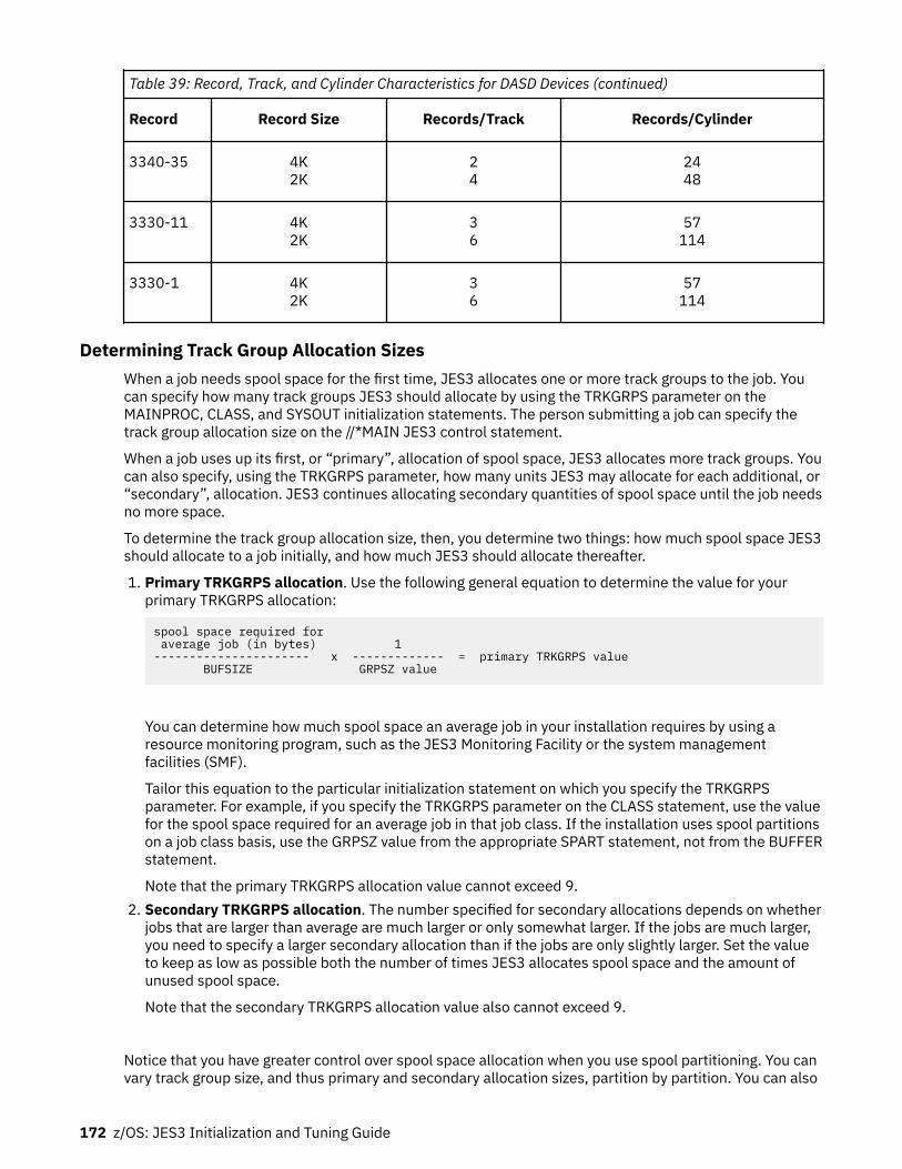
Table 39: Record, Track, and Cylinder Characteristics for DASD Devices (continued)
Record Record Size Records/Track Records/Cylinder
3340-35 4K2K
24
2448
3330-11 4K2K
36
57114
3330-1 4K2K
36
57114
Determining Track Group Allocation SizesWhen a job needs spool space for the first time, JES3 allocates one or more track groups to the job. Youcan specify how many track groups JES3 should allocate by using the TRKGRPS parameter on theMAINPROC, CLASS, and SYSOUT initialization statements. The person submitting a job can specify thetrack group allocation size on the //*MAIN JES3 control statement.
When a job uses up its first, or “primary”, allocation of spool space, JES3 allocates more track groups. Youcan also specify, using the TRKGRPS parameter, how many units JES3 may allocate for each additional, or“secondary”, allocation. JES3 continues allocating secondary quantities of spool space until the job needsno more space.
To determine the track group allocation size, then, you determine two things: how much spool space JES3should allocate to a job initially, and how much JES3 should allocate thereafter.
1. Primary TRKGRPS allocation. Use the following general equation to determine the value for yourprimary TRKGRPS allocation:
spool space required for average job (in bytes) 1---------------------- x ------------- = primary TRKGRPS value BUFSIZE GRPSZ value
You can determine how much spool space an average job in your installation requires by using aresource monitoring program, such as the JES3 Monitoring Facility or the system managementfacilities (SMF).
Tailor this equation to the particular initialization statement on which you specify the TRKGRPSparameter. For example, if you specify the TRKGRPS parameter on the CLASS statement, use the valuefor the spool space required for an average job in that job class. If the installation uses spool partitionson a job class basis, use the GRPSZ value from the appropriate SPART statement, not from the BUFFERstatement.
Note that the primary TRKGRPS allocation value cannot exceed 9.2. Secondary TRKGRPS allocation. The number specified for secondary allocations depends on whether
jobs that are larger than average are much larger or only somewhat larger. If the jobs are much larger,you need to specify a larger secondary allocation than if the jobs are only slightly larger. Set the valueto keep as low as possible both the number of times JES3 allocates spool space and the amount ofunused spool space.
Note that the secondary TRKGRPS allocation value also cannot exceed 9.
Notice that you have greater control over spool space allocation when you use spool partitioning. You canvary track group size, and thus primary and secondary allocation sizes, partition by partition. You can also
172 z/OS: JES3 Initialization and Tuning Guide

use spool space more efficiently by assigning large jobs to one spool partition and small jobs to anotherpartition and selecting their GRPSZ and TRKGRPS parameters accordingly.
See the section entitled “Using Spool Partitions” on page 162 for information about defining spoolpartitions.
Track Group Allocation Overrides
As noted above, you can specify the TRKGRPS parameter on the MAINPROC, CLASS, and SYSOUTinitialization statements and on the //*MAIN JES3 control statement. The order of overrides for job spoolspace allocation, beginning with the statement that overrides the others, is:
1. SYSOUT initialization statement (SYSOUT class basis)2. //*MAIN JES3 control statement (for a specific job)3. CLASS initialization statement (job class basis)4. MAINPROC initialization statement (for a specific processor)
Note: Installation exit routine IATUX33 can override the specification on the //*MAIN JES3 controlstatement.
If you do not specify the TRKGRPS parameter on any of the above statements, JES3 uses default values of1 for primary allocation and 2 for secondary allocation.
Managing Spool SpaceJES3 provides several facilities for managing spool space. These facilities help you balance the workloadacross spool partitions and gain additional spool space when available space runs low.
If you need to allocate more spool data sets, or if you have allocated too many spool data sets, you canadd or delete a spool data set over a warm start. You can also use operator commands to determine theamount of spool space remaining in particular spool data sets or partitions and to redistribute theworkload.
To gain additional spool space without adding spool data sets, you can use the *MODIFY,U,Q= commandto delete SYSOUT data sets that are no longer needed. If you need more spool space but also need tosave the jobs or SYSOUT on spool, the dump job (DJ) facility lets you copy spool data to tape. Then youcan use the dump job facility to restore the data when space becomes free.
Another way to gain additional spool space without adding data sets is to replace existing data sets withlarger ones. Replacing a spool data set requires a warm start. “Replacing a spool data set” on page 175gives the steps to follow.
Adding or deleting a spool data setYou can increase or decrease the spool capacity in your environment without performing a cold start byadding or deleting a spool data set. To determine whether the current spool capacity is appropriate foryour environment, you can monitor spool usage using the *I,Q,S operator command. To monitor the use ofchannel paths, control units, and spool data sets, use a system monitoring facility such as systemmanagement facilities (SMF), resource measurement facility (RMF), or JES3 monitoring facility (JMF).
To add a spool data set by using the *MODIFY CONFIG command, a hot start with refresh (HR) or a warmstart (W), follow the guidelines given in “Allocating Spool Data Sets” on page 160 and “Formatting SpoolData Sets” on page 160.
Deleting a spool data set requires more planning. You can delete a spool data set in several ways by usinga:
• Warm start• Hot start with refresh• *MODIFY CONFIG command
Defining and Managing Spool Data Sets 173

The general steps for each method are:
1. Prepare an updated spool data set definition.2. Stop new track group allocations from the spool data set.3. Empty the spool data set (for example, release currently allocated track groups).
As you work through the process of clearing the data set, you can use the *I Q,DD=ddname,U command tocheck on your progress.
For example, if you want to delete a spool data set, SPOOL3, on a system. Before you begin the process,you can issue *I Q,DD=SPOOL3,U to view the jobs with allocations on the data set:
*i Q,DD=SPOOL3,u IAT8752 SPOOL3 TOTAL IN USE 10 TRKGPS IAT8752 SPOOL3 TOTAL IN USE BY JES3 4 TRKGPS IAT8752 SPOOL3 TOTAL IN USE BY JOBS 6 TRKGPS IAT8753 SPOOL3 USERS FOUND= 2 JES3 5 JOBS; 7 DISPLAYED IAT8754 SPOOL3 : JOB IBMUSER (JOB00016) 2 TRKGPS, 2% IAT8754 SPOOL3 : JOB JES3STT (JOB00000) 2 TRKGPS, 2% IAT8754 SPOOL3 : JOB JES3INIT (JOB00000) 2 TRKGPS, 2% IAT8754 SPOOL3 : JOB SDSF (JOB00004) 1 TRKGPS, 1% IAT8754 SPOOL3 : JOB CREATEHC (JOB00009) 1 TRKGPS, 1% IAT8754 SPOOL3 : JOB MAP0421 (JOB00021) 1 TRKGPS, 1% IAT8754 SPOOL3 : JOB MAP0913 (JOB00022) 1 TRKGPS, 1% IAT8755 INQUIRY ON SPOOL DATA SET USAGE COMPLETE
The display shows that JES3 (JOB00000) occupies space on the data set. JES3STT is the job name that isgiven to spool space used internally by JES3 for information that persists across a JES3 restart or an IPL.JES3INIT represents spool space that is used to contain the data contained in your JES3 initializationstatements.
The first step is to prepare an updated spool definition. If you want to use the *MODIFY CONFIGcommand to delete the SPOOL3 data set and you define your spool data sets with DYNALLOC statements.remove the DYNALLOC statement for SPOOL3 and clean up references to it, such as TRACK or FORMATstatements. The updates for a hot start with refresh and warm start are similar. For a warm start, youmight need to remove the appropriate DD statement from the JES3 cataloged start procedure. See z/OSJES3 Commands for more information about the operator activities that are required to add or delete aspool data set.
The next step in the delete process is to drain the target spool data set by issuing a *FQ,DD=ddname,DRAIN command. This prevents new allocations from the data set and relocates theJES3STT records. Though a subsequent *I Q,DD=ddname,U command might display JES3STT space onthe spool, all of the STT records in that space are moved.
The next step is to clear the spool data set. Some ways to reclaim the spool space are:
• CANCEL jobs, if practical. For example, *F J=9,C reclaims the space for job CREATEHC.• Dump eligible jobs by using the JES3 dump job facility (see Dump job facility in z/OS JES3 Commands).
In this example, this reclaimed the space used by jobs MAP0421 and MAP0913.• Logoff or CANCEL TSO user jobs. IBMUSER logged off and its space was released.• Process Job0 output (use *I U,Q=WTR,J=0 or *I Q,Q=HOLD,J=0 to see if any output exists).• Cancel remaining jobs by running a *F Q,DD=ddname,CANCEL command.• End started tasks. The process varies depending on the properties of the started task. For example,
SDSF was stopped (P SDSF) to release its space.
Delete the spool by running the *F CONFIG command. Alternatively, perform a hot start with refresh byusing an updated initialization stream. The hot start with refresh is unsuccessful if the initialization data(JES3INIT) resides on the volume. In this case, the options are:
1. Use the *F CONFIG command to delete the spool data set (recommended). The command moves theinitialization files to other spool data sets.
2. Use a hot start with refresh with the original set of spools (while the spool to be deleted is in drainedstatus). Then, do another hot start with refresh to delete the spools.
174 z/OS: JES3 Initialization and Tuning Guide

Replacing a spool data setYou can replace or delete a spool data set using the *MODIFY CONFIG command, a hotstart with refresh,or a warm start using the procedures that follow. You can create the new data set on a volume or devicetype that is different than the one being replaced. You can also change the size of the data set andredefine the single track table (STT) range using the STT or STTL parameter on the TRACK or FORMATinitialization statement.
When you replace a spool data set, JES3 cancels all jobs with data on the replaced spool data set. If thereplaced data set contains STT records, JES3 might lose information that could result in the loss of jobs inthe system. STT records include information such as the status of devices, DJC network data, deadlinequeue data, volume unavailable data, dynamic allocation checkpoint data, output service checkpointdata, JESNEWS, device fencing data, virtual unit status, GMS status, and FSS checkpoint data. If STT datais lost, JES3 issues messages that allow you to take the appropriate recovery actions.
You can migrate STT data to a different set of spool data sets by running the *F Q,DD=ddname,DRAINcommand. To migrate job data from the affected spools, you can use the *CALL,DJ dump jobs facility tooffload the data to different spool data sets.
As a last resort, you can cancel all jobs on a specific data set using the *F Q,DD=ddname,CANCELcommand. After you cancel the jobs, the user can resubmit them. You can then replace the spool data setat a convenient time; you must use the same ddname for the new spool data set that was used for the oldspool data set.
Replacing a spool data set dynamically
To replace a spool data set dynamically, use the following procedure:
1. Complete the prerequisites described previously, in “Replacing a spool data set” on page 175.2. Segregate the JSAM-related statements, which includes all statements up to and including ENDJSAM,
into a separate member of the initialization stream data set. Use the INCLUDE statement in yourJES3INxx member to ensure that the same configuration will be used during any subsequent JES3starts that read the initialization stream.
3. Run the *F CONFIG,M=member,P=xx command to remove the data set.4. Add a DYNALLOC statement for the new spool extent to the JSAM member and add a new TRACK or
FORMAT statement. If you use a TRACK statement, format the new data set using the procedureoutlined in “Formatting with IEBDG” on page 161.
5. Run another *MODIFY CONFIG command to add the new extent.
Replacing a spool data set using a warm start
To replace a spool data set by using a warm start, use the following procedure:
1. If you allocated the old spool data set by using a JES3 cataloged procedure, update the DD statementin the cataloged procedure to reflect information about the new data set. You might need to changethe data set name, device number, device type, or volume serial number. Do not change the ddname.
If you allocated the old spool data set by including a DYNALLOC statement in the initialization stream,update the optional parameters as necessary. Do not change the ddname.
2. If the old spool data set is cataloged, replace its catalog entry with an entry for the new spool data set.3. If the new spool data set is unformatted and your initialization stream currently includes a TRACK
statement for the old spool data set, replace it with a FORMAT statement. Otherwise, do not alter yourTRACK or FORMAT statement.
Note: JES3 initialization requires additional time if the data set needs to be formatted; you canpreformat the data set using the procedure outlined in “Formatting with IEBDG” on page 161.
4. Ensure that no job or STT data resides on the data set. Run the *I Q,DD=ddname command andcheck the number of track groups that are allocated. If there is still data on the data set, drain the dataset using the *F Q,DD=ddname,DRAIN command.
Defining and Managing Spool Data Sets 175

5. Perform a warm start. Specify WR or WAR as the restart mode. JES3 will prompt you to enter theddnames of replaced spool data sets (message IAT4009 for unformatted spool data sets and messageIAT4008 for formatted spool data sets). JES3 will then cancel all jobs that have track groups allocatedto the spool data sets being replaced.
Moving a spool data set to another DASD volumeIf you must move the contents of a spool data set to another DASD volume, you must attempt to do itwhile the JES3 global is down.
If you cannot copy the volume while JES3 is down, perform a hot start with the data set that is notallocated or the DD statement for the data set removed from the JES3 start procedure. During JES3initialization, JES3 considers the spool data set unavailable. Some abends might occur (for example, 1FB)after JES3 starts for jobs that attempt to access data on the unavailable volume.
The JES3 spool data is addressed using an addressing scheme that is relative to the beginning of thevolume. The spool data set on the target volume has to start and end on the same cylinder and track asthe source data set. IBM suggests using absolute track allocation to accomplish it.
After moving the data to the new DASD volume, perform a hot start with the data set (on the new volume)allocated or with the DD statement for the data set included in the JES3 start procedure. Before issuingthe *S JSS command on the global, JES3 on all locals must be stopped and started again.
When moving a spool data set that contains single track table (STT) records, STT expansion tables mustbe kept intact so that the jobs that they map can be recovered. See “Replacing a spool data set” on page175 for more information regarding replacing spool data sets that contain STT records.
To find out whether a spool extent contains an STT, you can issue the *I Q,DD=ddn command. For moreinformation, see z/OS JES3 Commands.
You can direct the STT allocation to a subset of spool extents using the TRACK or FORMAT initializationstatements. See z/OS JES3 Initialization and Tuning Reference for more information.
Balancing the workload across spool partitionsTo help you determine the workload distribution across the spool partitions, JES3 provides commandsthat you can use to:
• Determine the amount of space remaining in each spool data set (*I,Q,DD=ddname)• Determine the amount of space remaining in each spool partition (*I,Q,SP=spart)• Determine where spool data overflows to when each spool partition becomes full (*I,Q,SP=spart,O)• Determine if any spool partitions are overflowing, in a minimum or marginal spool space condition, or
out of space (D R,L,KEY=JSAM)
Note: D R,L,KEY=JSAM is an MVS system command. For more information , see z/OS MVS SystemCommands
Using the SPLIM parameter on the SPART and BUFFER initialization statements, you can have JES3 notifyyou when space in a spool partition begins running low and when it runs critically low.
BUFFER,SPLIM=(min,marg)SPART,NAME=partitionname,SPLIM=(min,marg)
The min (minimal) and marg (marginal) subparameters define percents of the total number of trackgroups in the partition that remain available. The value specified on a SPART statement overrides thevalue specified on the BUFFER statement.
A good value for the marg subparameter is the point at which spool performance begins falling because ofincreased seek time. Seek time increases as JES3 writes and reads data farther from the middle of thevolume. A good value for the min subparameter is the point at which spool performance becomes
176 z/OS: JES3 Initialization and Tuning Guide

severely degraded. Another good value is the point at which active jobs will likely need to overflow intoanother partition.
JES3 issues messages indicating when a spool partition reaches a marginal or minimal condition.
If you want to redistribute the workload, there are commands that let you:
• Respecify a spool data set as a member of another spool partition:
*F,Q,DD=ddn,SP=spart...• Respecify the spool partition that JES3 is to use for specific processors:
*F,G,main...• Respecify the spool partition that JES3 is to use for specific job classes:
*F,C=cls...• Respecify the spool partition that JES3 is to use for the overflow of spool data when a spool partition
becomes full:
*F,Q,SP=spart,O=spart
If this command would result in circular overflow, JES3 prevents the modification and issues a messagerejecting the command.
During the next warm start, the initialization statements will override changes made using thesecommands. To retain the changes, make the same changes to the initialization stream. During a hot startor hot start with refresh, changes made using these commands remain in effect, except the *F,G and*F,C=cls commands.
Over a warm or cold start, you can make additional changes to the spool configuration by changing theinitialization stream. You may add or delete partitions, change the use of any partition, or move spool datasets from one partition to another. (Try not to move a spool data set to a partition having a different trackgroup size. Having spool data sets with different track group sizes within one partition could result inperformance problems.) Any spool partition created without any spool data sets (a “dummy partition”)should overflow. Otherwise, if a job requests the dummy partition, JES3 will never select the job forexecution.
Deleting Output Data SetsYou can delete output data sets from the output service hold, writer, or BDT queue using the *MODIFY,Uoperator command. The *MODIFY,U command allows you to specify the criteria by which JES3 selectsdata for deletion. For details about using the JES3 *MODIFY command see z/OS JES3 Commands.
You can code installation exit IATUX48 to override the operator command parameters that select the datasets for deletion. For information about using IATUX48 see z/OS JES3 Customization.
Freeing Spool Space Using the Dump Job FacilityYou can free spool space without losing jobs already in the system by using the dump job (DJ) facility. Usethis facility to copy one or more jobs to tape, then let JES3 purge the job. When spool space becomesavailable, use the dump job facility to restore the job(s) to the system. Call the dump job facility as a DSP,using operator commands that are explained in z/OS JES3 Commands.
How to Use Performance Measurement Tools to Tune JES3 SpoolJES3 performance is highly dependent upon efficient spool access. JES3 can perform poorly if your spoolvolumes or spool DASD channels are too busy or if you do not have sufficient spool space. Use thefollowing reports to measure spool space and spool access:
• Check the Spool Space Utilization Snapshot portion of the JMF report or issue an *INQUIRY,Q,DD=command to display the amount of spool space being used. A reasonable limit is 35% - 40%. If the totalspool space remaining is less than 60%, consider adding additional spool volumes.
Defining and Managing Spool Data Sets 177

• Check the I/O Device Activity portion of the RMF report to measure the amount of time spool is busy. Areasonable limit is 30% to 40%. You can reduce the amount of time that spool is busy by addingadditional spool volumes.
• Check the Channel Path Activity portion of the RMF report to obtain the percentage of time a spoolchannel is busy. A reasonable limit is 25% - 30%. To improve spool availability, move your spool packsto the least busy channel.
The following table summarizes the actions you can perform to tune spool:
Table 40: Summary of Spool Tuning Techniques
Spool Tuning Task Tuning Actions
Improve average seek time or avoidlockouts
Allocate only one spool data set per spool volume. When a volumecontains more than one spool data set, the average seek time to accessthe data increases, which can degrade JES3 performance.
Improve spool space utilization forcomplexes that support mostlysmall jobs and TSO users
Specify a group size value that is less than half the size of a cylinder forthe spool device type. Use the GRPSZ= keyword on the BUFFER or SPARTinitialization statements to specify the group size. A small value alsoreduces seek time on moveable head devices.
Reduce the amount of time that ajob must wait to receive additionalspool space
Specify a track group size value roughly the number of records percylinder. Specifying a larger value can improve performance if yourworkload consists mostly of jobs that produce large amounts of output.
Gain additional spool space withoutadding additional spool data sets
Delete unused output data sets using the JES3 *MODIFY,U command orreplace existing spool data sets with larger data sets. Replacing spooldata sets however, requires a warm start. Use the Dump Job DSP torelease spool space by moving jobs to tape. You can restore those jobswhen spool space becomes available.
Reduce spool I/O Specify a buffer size of 4K. However, specifying a buffer size of 4K usesmore virtual storage than a 2K buffer. Use the BUFSIZE= keyword of theBUFFER initialization statement to specify the size of JES3 buffers.
Reduce spool space usage Specify a buffer size of 2K. Specifying a buffer size of 2K, however,increases spool I/O.
Improve spool access 1) Allocate the JCT data set on its own spool volume or on a low-usagespool pack. Avoid placing the JCT data set on a catalog volume becauseof the reserve/release interference. Device busy for this data set shouldnot exceed 10%.
2) Center the single-track-table (STT) across all spool volumes ordedicate a separate spool extent to the STT using the STT parameter onthe TRACK initialization statement. For fixed head devices, allocatecylinders under the fixed heads.
3) If you can access your spool devices through an alternate control unit(such as string switching), enter yes for the ALTCTRL feature on HCD'sDefine Device Parameters / Features panel.
4) Move one or more of your spool packs to the least busy DASD channel.
Limit processor contention forspool volumes
Use spool partitioning.
Optimize spool space usage byusing different track group sizes
Use spool partitioning.
Ensure spool space availability forcritical work
Use spool partitioning.
178 z/OS: JES3 Initialization and Tuning Guide

Table 40: Summary of Spool Tuning Techniques (continued)
Spool Tuning Task Tuning Actions
Improve spool recovery and spoolspace management
Use spool partitioning.
Defining and Managing Spool Data Sets 179

180 z/OS: JES3 Initialization and Tuning Guide

Chapter 7. Defining Consoles and Message Routing
This section provides information about defining and tailoring consoles that you use to control youroperating system. It also describes how to control where and how messages appear in your installation.
Defining consoles and message routing requires you to coordinate definitions in the MVS configurationprogram, the MVS SYS1.PARMLIB data set, and your JES3 initialization stream. These statements and thedocuments in which you can reference them are cited throughout this topic.
Defining ConsolesConsoles are devices that you use to enter commands and receive messages from JES3, MVS andapplication programs. Consoles fall into one of the following classes:
• Multiple console support (MCS) consoles• RJP (Remote job processing) consoles
MCS consoles are devices that you can physically attach to global or local processors. These consolesallow you to control the sysplex. See z/OS MVS Planning: Operations for information about MCS consolesin a sysplex environment.
RJP consoles are devices that you attach to the JES3 global as part of a remote workstation usingtelecommunications lines. RJP permits you to submit jobs to and receive output at workstations that areat some distance from your installation.
Defining MCS ConsolesThe term MCS consoles refers to:
• MCS-managed consoles• Extended MCS consoles
You must define MCS consoles in the CONSOLxx member of the MVS SYS1.PARMLIB data set. ExtendedMCS consoles are defined and activated through programs such as TSO/E and are authorized throughRACF for use as operator consoles. MCS consoles accept MVS commands based on their MCS authoritylevel or RACF authorization.
Any MCS console with master authority is the principal device for communication with MVS. Any MCSconsole with master authority has the highest MCS authority level assigned to it. MCS consoles withmaster authority can enter MVS commands of any authority level, and can receive all messages. MCSsecondary consoles cannot issue all MVS commands or respond to all action messages; these consolesreceive only those messages specifically routed to them.
MCS consoles accept all JES3 commands except *FREE (non-directed) which affects console screenpresentation.
JES3 on a local processor accepts only the following commands:
• *CALL, *START, *CANCEL,DSI• *CALL, *CANCEL,JMF• *CALL, *START, *CANCEL,VARYL• *RETURN• *DUMP• *TRACE
© Copyright IBM Corp. 1988, 2017 181

The MCS command authority level that you specify in the CONSOLxx member of the MVS SYS1.PARMLIBdata set determines the JES3 authority level for MCS consoles. See “Using JES3 to Authorize Commandsfrom MCS Consoles” on page 84 for information about defining console authority.
Defining RJP ConsolesRemote job processing consoles can be either bisynchronous communication (BSC RJP) consoles orsystem network architecture (SNA RJP) consoles. You define a BSC RJP console during initialization usinga JES3 CONSOLE initialization statement. The name you specify on the JNAME= keyword of the JES3CONSOLE initialization statement must match the name you specify on the N= keyword of the JES3RJPTERM initialization statement.
If you want a workstation to have the facilities of a JES3 console, you must code the workstation nameand console options on the JES3 CONSOLE initialization statement for that console.
You can define simulated consoles for workstations that do not have real consoles. In this case, you enterconsole commands through the card reader, and receive messages on the terminal's printer.
You also define a SNA RJP console during initialization using a JES3 CONSOLE initialization statement.The name you specify on the JNAME= keyword of the CONSOLE statement must match the name youspecify on the N= keyword of the RJPWS statement.
JES3 Console ManagementJES3 console service manages communication between consoles and JES3. In managing consolecommunication, console service:
• Provides operator communication with JES3 functions• Manages the buffers used for communication• Provides processing for input and output messages
Operator CommunicationYou communicate with JES3 dynamic support programs (DSPs) using JES3 commands. When a JES3 DSPinitiates execution, it must identify itself to console service. You can refer to JES3 DSPs by the name ornumber of the device assigned to the dynamic support program.
Input ProcessingInput commands which you initiate are directed to the operating system.
You can enter all JES3 commands (except *DUMP and *RETURN) from a card reader (CR), tape reader(TR), or disk reader (DR). You can use the tape or disk reader to enter repetitive commands based onsystem requirements (such as shift change). Any output messages generated from a card reader, tapereader, or disk reader are displayed at the console from which you called the reader.
You can enter a pause command from any reader through the use of the //*PAUSE control statement.JES3 recognizes this statement only if the statement appears before the first //JOB statement in the job'sinput stream. When the //*PAUSE statement is recognized, the reader issues a message and waits for areply. (For example, if *CALL and *START DSP commands are entered through the reader, the //*PAUSEstatement can be used to stop the reader after the *CALL,dsp command is entered. This allows the DSP tobe readied before the *START command is executed. When the DSP is ready, you can start the reader tohave the next command executed.) The use of the //*PAUSE statement is intended primarily for systemcheckout and test.
MCS Console ManagementJES3 allows you to use the multiple console support (MCS) facility of MVS. MCS provides the followingsupport:
182 z/OS: JES3 Initialization and Tuning Guide

• Backup console service: When a console fails, you can specify an alternate console to processmessages that were being sent to the original console. In this case, the routing codes of the twoconsoles are merged.
• Operator action messages: On MCS consoles configured in conversational mode or in roll-deletablemode, action messages remain on the screen until deleted by the program issuing them or until youdelete them manually.
• Screen-oriented displays on display consoles: At system initialization, the MCS console screen can bedivided into multiple screen areas for receiving these displays in out-of-line or non-message screenareas. If operator action is unnecessary, MCS consoles can also be designated as output-only consoles.
• Authority levels: You can assign authority levels to allow or restrict the types of MVS commands that anoperator can enter at a console. See “Using JES3 to Authorize Commands from MCS Consoles” on page84 for information about defining console authority.
• Console LOGON: You can require that operators LOGON to MCS consoles by specifying options in theCONSOLxx member of the MVS SYS1.PARMLIB data set. You can also activate RACF to ensure that theperson attempting to gain access to an operator console has the authority to do so. See z/OS MVSInitialization and Tuning Guide for additional information about SYS1.PARMLIB. See “AuthorizingConsole Access” on page 68 for additional information about using RACF to restrict console access.
• Log facilities: You can use the operations log, systems log, or a real device to record the hardcopy log. • Enhanced display capability: You can control several characteristics of MCS console such as reverse
video, extended highlighting and seven color support.• NOJES3 Option: If both JES2 and JES3 are installed on the same system and JES2 is running alone,
then initialize with the NOJES3 option to enable the short form reply. See z/OS MVS Initialization andTuning Reference for more information on the CON= parameter.
Entering commandsYou can enter JES3 commands from all consoles.
You cannot enter JES3 commands to inquire about or modify the status of MCS consoles. You must usethe equivalent MVS commands instead. For example, MCS consoles reject the JES3 *FREE command(however, you can issue *FREE,con which is also known as a directed *FREE command from MCSconsoles.
JES3 on a local processor accepts only the following commands:
• *RETURN• *DUMP• *CALL, *CANCEL,JMF• *CALL, *START, and *CANCEL,VARYL• *CALL, *START, *CANCEL,DSI• *TRACE
During JES3 initialization, you should not enter any JES3 commands other than the *DUMP, *RETURN, and*START JSS commands. You should always use equivalent MVS commands.
Defining the hardcopy logThe hardcopy medium (also known as the hardcopy log) records command and message traffic for yoursystems. MVS and JES3 provide three forms of the hardcopy medium:OPERLOG
centrally records command and message traffic for systems in a sysplex in Message Data Block (MDB)format.
Defining Consoles and Message Routing 183
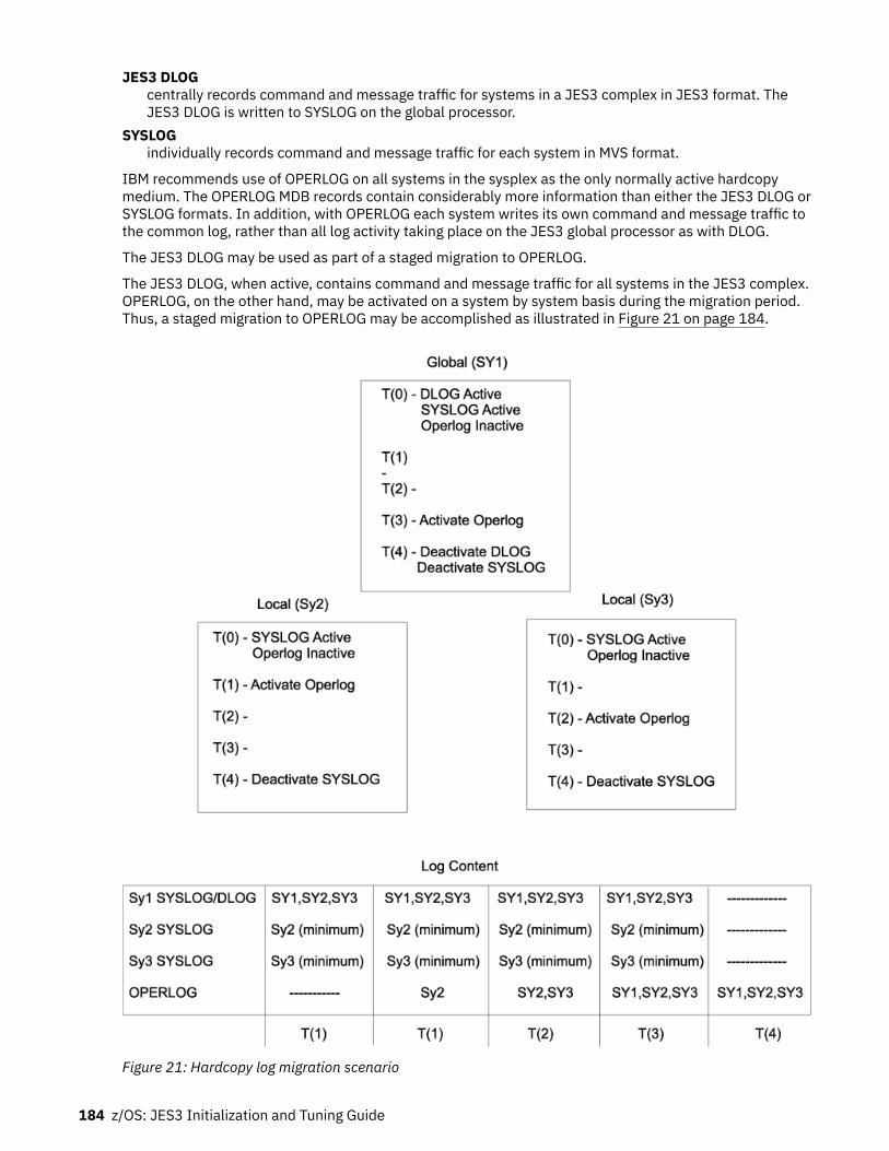
JES3 DLOGcentrally records command and message traffic for systems in a JES3 complex in JES3 format. TheJES3 DLOG is written to SYSLOG on the global processor.
SYSLOGindividually records command and message traffic for each system in MVS format.
IBM recommends use of OPERLOG on all systems in the sysplex as the only normally active hardcopymedium. The OPERLOG MDB records contain considerably more information than either the JES3 DLOG orSYSLOG formats. In addition, with OPERLOG each system writes its own command and message traffic tothe common log, rather than all log activity taking place on the JES3 global processor as with DLOG.
The JES3 DLOG may be used as part of a staged migration to OPERLOG.
The JES3 DLOG, when active, contains command and message traffic for all systems in the JES3 complex.OPERLOG, on the other hand, may be activated on a system by system basis during the migration period.Thus, a staged migration to OPERLOG may be accomplished as illustrated in Figure 21 on page 184.
Figure 21: Hardcopy log migration scenario
184 z/OS: JES3 Initialization and Tuning Guide

Initially, at time t(0), DLOG is active and SYSLOG is active on all systems. In this example, we elected toactivate the Operations log on local SY2 first. At this point forward, time t(1), the hardcopy log generatedby SY2 will be written to the Operations log.
At time t(2), the Operations log is activated on SY3. Now the hardcopy log from both locals will be writtento the Operations log.
At time t(3), the Operations log is activated on SY1. Now the hardcopy log from each system will bewritten to the Operations log. The sysplex now has two sysplex-wide logs: a JES3 formatted log written byDLOG, and the operations log.
From time t(0) through t(3), the JES3 SP5.2.1 DLOG facility will provide a JES3 formatted log containingmessages from all systems in the JES3 complex.
At time t(4), the DLOG facility and SYSLOG are deactivated on each system. The sysplex-wide logremaining is the Operations log.
Recording message trafficJES3 and MVS record all message traffic in the system log. Each DLOG entry includes a time stamp, a datestamp, and the text of the message. Each entry in the log can also include:
• The JES3 destination class to which the message was routed.• The console from which a command was entered• The console to which a message was routed.• The name of the job associated with the message.• Whether the system suppressed the message from console display.• The system ID for messages issued by another processor.• Flags indicating unusual conditions or marking lines of special interest.
Figure 22 on page 185 shows sample log entries.
Figure 22: Sample Log Entries (with 2-digit-year dates)
Defining Consoles and Message Routing 185

RulesThe following rules apply:
• For DLOG, the system log is spooled and periodically printed by JES3 output service. By default, the logis printed every 500 lines to output class A. To change these defaults, code the LOGLMT and LOGCLSparameters of member IEASYSnn of the MVS SYS1.PARMLIB data set. You can also print the disk log byentering the MVS WRITELOG command from the global.
• You can specify during initialization whether you want JES3 DLOG to be active. You can also usecommands to dynamically changes the status of JES3 DLOG. Through the use of *MODIFY,O commands,you can enable or disable DLOG. However, JES3 rejects any command that would leave your installationwithout some form of hardcopy log.
• You can specify which MVS commands you want recorded in the system log using the HARDCOPYparameter in the CONSOLxx member of the MVS SYS1.PARMLIB data set. For information aboutSYS1.PARMLIB see z/OS MVS Initialization and Tuning Guide.Also, the HCFORMAT keyword on theHARDCOPY parameter provides you the option of recording year dates in 2- or 4-digit format. Comparethe sample sections of the log entries in Figure 22 on page 185 to Figure 23 on page 186 for thedifferences in the fields that contain the console name and year as follows:Year Date Format
Column 2-Digit
6-13 - Console Name 15-16 - 2-digit year4-Digit
5-12 - Console Name 13-16 - 4-digit year
Figure 23: Sample Log Entries (with 4-digit-year dates)
Defining message routingYour system issues messages for many reasons. For example, MVS and JES3 issue messages to informyou of your system's status, on behalf of jobs that require resources, in response to commands, or toinstruct you to perform some type of action.
186 z/OS: JES3 Initialization and Tuning Guide

MVS and JES3 together determine where and how messages are routed and presented in yourinstallation. You can use many facilities to control message traffic including:
• JES3 initialization statements• Statements in members of the MVS SYS1.PARMLIB data set• The MVS message processing facility (MPF)• Automation packages• Macros used to issue messages• JES3 and MVS installation exits• JES3 and MVS commands.
This topic provides information about how to control message routing using JES3 initializationstatements. Overviews of non-JES3 facilities such as MPF and automation packages, are provided tointroduce you to those topics. You should refer to the appropriate document for detailed informationabout using those facilities. The following documents also contain information about message routing:
• z/OS JES3 Customization• z/OS JES3 Commands• z/OS MVS Initialization and Tuning Guide• z/OS MVS Planning: Operations
To control message routing in a JES3/MVS environment, you must first understand the following basicconcepts:
• Where and how messages originate• Where messages can go• The general path of messages• JES3 destination classes• MVS routing codes• Message routing exceptions
The following sections describe the tasks of controlling message traffic using JES3 initializationstatements, message retention facilities, the MVS message processing facility, and automation packages.
Where and How Messages OriginateJES3, MVS, and application programs can originate messages on both global and local processors. Youcan also issue messages from installation exits and user-written dynamic support programs using thefollowing macros:
• The JES3 MESSAGE macro• The MVS WTO or WTOR macro.
The JES3 MESSAGE Macro
Most JES3 messages are issued using the MESSAGE macro. You can specify many routing and displayoptions using this macro, including the following characteristics:
• Routing• Logging• Retention• Presentation• Deletion
The MESSAGE macro always converts messages into WTOs or before message routing begins. Thefollowing sections generically refer to messages issued by a WTO or WTOR macro as WTOs. See z/OSJES3 Customization for information about using the JES3 MESSAGE macro.
Defining Consoles and Message Routing 187

The MVS WTO and WTOR Macros
Both JES3 and MVS can use the MVS write-to-operator (WTO) or write-to-operator-with-reply (WTOR)macros to issue messages.
You can specify information on the WTO and WTOR macro that is similar to that on the MESSAGE macro.In addition, you can also specify whether subsystems can or cannot modify the message's original routinginformation. See z/OS MVS Programming: Authorized Assembler Services Reference SET-WTO forinformation about using the WTO or WTOR macro.
Where messages can goMVS and JES3 present messages in many places. Notice that the term present is used rather than display,because message destinations can be internal, such as disk logs and automation packages in addition to,or instead of external destinations, such as operator display consoles and hardcopy logs. Depending onthe JES3/MVS routing algorithms and the routing decisions you make, the system may or may not presentmessages to:
• MCS consoles• The hardcopy log• The MVS message processing facility (MPF)• The MVS action message retention facility• Automation packages.
Understanding the General Path of a MessageA message can pass through many functions of MVS or JES3 along the route to its final destinations. Manyof these functions can add, change, or delete a message's original routing and presentationcharacteristics. Figure 24 on page 189 and Figure 25 on page 190 illustrate the general path of amessage. These figures include optional functions such as the MVS message processing facility (MPF),installation exits and automation packages. There are special exceptions to this path that are discussed inthe following sections:
Path of message issued from a local processor
188 z/OS: JES3 Initialization and Tuning Guide
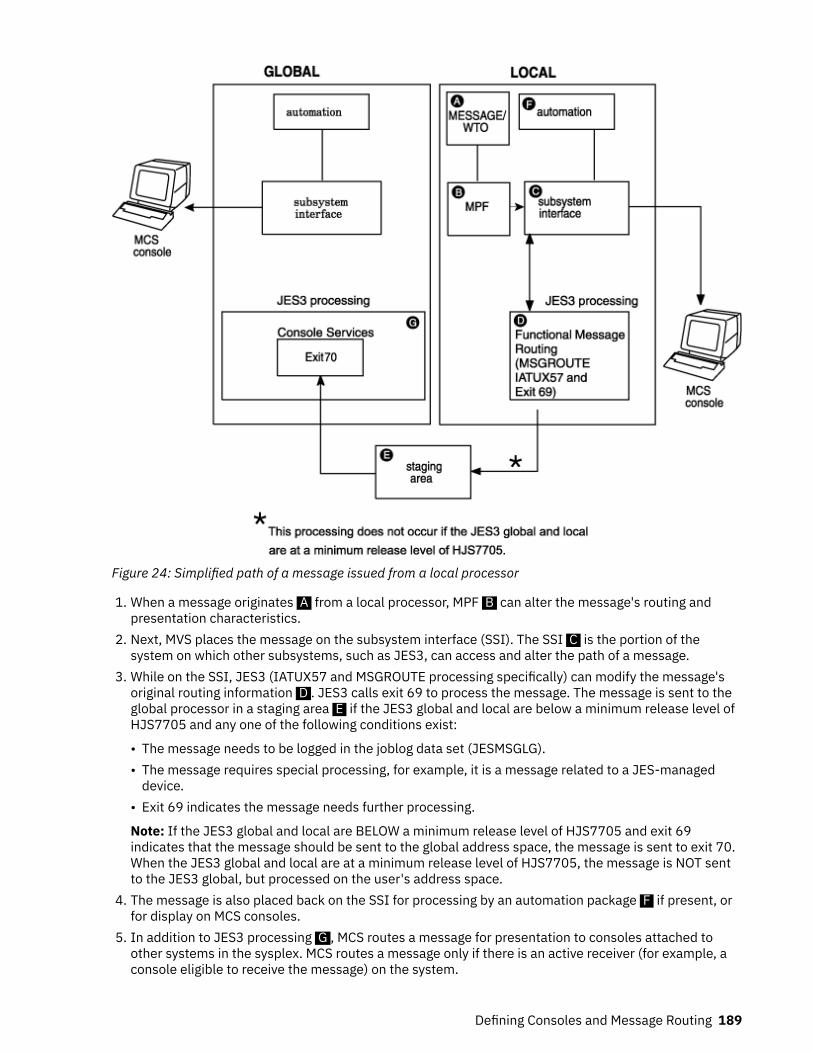
Figure 24: Simplified path of a message issued from a local processor
1. When a message originates A from a local processor, MPF B can alter the message's routing andpresentation characteristics.
2. Next, MVS places the message on the subsystem interface (SSI). The SSI C is the portion of thesystem on which other subsystems, such as JES3, can access and alter the path of a message.
3. While on the SSI, JES3 (IATUX57 and MSGROUTE processing specifically) can modify the message'soriginal routing information D . JES3 calls exit 69 to process the message. The message is sent to theglobal processor in a staging area E if the JES3 global and local are below a minimum release level ofHJS7705 and any one of the following conditions exist:
• The message needs to be logged in the joblog data set (JESMSGLG).• The message requires special processing, for example, it is a message related to a JES-managed
device.• Exit 69 indicates the message needs further processing.
Note: If the JES3 global and local are BELOW a minimum release level of HJS7705 and exit 69indicates that the message should be sent to the global address space, the message is sent to exit 70.When the JES3 global and local are at a minimum release level of HJS7705, the message is NOT sentto the JES3 global, but processed on the user's address space.
4. The message is also placed back on the SSI for processing by an automation package F if present, orfor display on MCS consoles.
5. In addition to JES3 processing G , MCS routes a message for presentation to consoles attached toother systems in the sysplex. MCS routes a message only if there is an active receiver (for example, aconsole eligible to receive the message) on the system.
Defining Consoles and Message Routing 189

The message is placed on the SSI on all systems that receive the message. MPF processing takes placeonly on the originating system. The GLOBMPF parameter on the JES3 CONSTD initialization statementcan be used to indicate MPF should be invoked on the global processor for all messages routed to theglobal processor regardless of the originating system.
Path of a message issued from a global processor
Figure 25: Simplified path of a message issued from a global processor
Messages that originate on a global processor travel a path similar to that of a message issued on a localprocessor.
1. When a message originates A on the global processor, MPF B can alter the message's routing andpresentation characteristics.
2. Next, MVS places the message on the subsystem interface (SSI). The SSI C is the portion of thesystem on which other subsystems, such as JES3, can access and alter the path of a message.
3. While on the SSI, JES3 (IATUX57 and MSGROUTE processing specifically) can modify the message'soriginal routing information D . JES3 calls exit 69 to process the message. The message is sent to theJES3 global address space if the JES3 is at a release level below HJS7705 and any one of the followingconditions exist:
• The message needs to be logged in the joblog data set (JESMSGLG).• The message requires special processing, for example, it is a message related to a JES-managed
device.• Exit 69 indicates the message needs further processing.
4. Depending upon the results of JES3's processing, the message can be packaged in a staging area andsent to the JES3 global address space E for further processing. The message is also placed back onthe SSI for processing by an automation package F if present, or for display on MCS consoles.
5. If exit 69 indicates that the message should be sent to the global processor, the message is sent to exit70.
190 z/OS: JES3 Initialization and Tuning Guide

Note: When the JES3 global and local are at a minimum release level of HJS7705, the message is NOTsent to the JES3 global, but processed on the user's address space.
6. In addition to JES3 processing, MCS routes a message for presentation to consoles attached to othersystems in the sysplex. MCS routes a message only if there is an active receiver (for example, a consoleeligible to receive the message) on the system.
The message is placed on the SSI on all systems that receive the message. MPF processing takes placeonly on the originating system.
JES3 Destination Classes and MVS Routing CodesJES3 uses 95 destination classes to route messages to MCS and RJP consoles. You can define whichmessages you want displayed on a JES3 RJP console by specifying one or more destination classes on theDEST= keyword of the JES3 CONSOLE initialization statement.
MVS uses 128 routing codes to route messages to MCS consoles. You can define which messages an MCSconsole displays by specifying routing codes on the ROUTCODE keyword of the CONSOLE statement in theCONSOLxx member of the MVS SYS1.PARMLIB data set. Each destination class corresponds to an MVSrouting code. However, no JES3 equivalent exists for routing codes 1, 2, 4, 5, 6, and 11 to 40. Table 41 onpage 191 shows the 95 JES3 destination classes and their corresponding MVS routing codes.
Table 41: Valid Destination Classes and Their Corresponding Routing Codes
JES3DestinationClass
Equivalent MVSRouting Code/Function
Destination Class Purpose
ALL Broadcast Messages of general interest. These messages are received by MCSconsoles receiving broadcast messages and JES3 RJP consoles whichinclude DEST=ALL in their destinations.
ERR 10 Equipment failure and JES3 failsoft and problem messages.
JES 42 General information about JES3.
LOG 41 General information about jobs.
MLG Hardcopy All input and output messages.
SEC 9 All security messages.
TAP 3 Messages about JES3-controlled tape requirements.
TP 8 Messages about teleprocessing.
UR 7 Messages about JES3-controlled unit-record equipment.
DALLor D1-D22
43-64 Messages about a user-defined console configuration. Theexact JES3 destination class-routing code mappings are:
D1=43 D5=47 D9=51 D13=55 D17=59 D21=63D2=44 D6=48 D10=52 D14=56 D18=60 D22=64D3=45 D7=49 D11=53 D15=57 D19=61D4=46 D8=50 D12=54 D16=58 D20=62
Defining Consoles and Message Routing 191

Table 41: Valid Destination Classes and Their Corresponding Routing Codes (continued)
JES3DestinationClass
Equivalent MVSRouting Code/Function
Destination Class Purpose
MALLor M1-M32
65-96 Messages unique to a JES3 main. Use the MDESTparameter of the MAINPROC statement to define the destinationclass for messages about specific mains. The exact JES3destination class-routing code mappings are:
M1=65 M7=71 M13=77 M18=82 M23=87 M28=92M2=66 M8=72 M14=78 M19=83 M24=88 M29=93M3=67 M9=73 M15=79 M20=84 M25=89 M30=94M4=68 M10=74 M16=80 M21=85 M26=90 M31=95M5=69 M11=75 M17=81 M22=86 M27=91 M32=96M6=70 M12=76
SALLor S1-S32
97-128 Messages pertaining to JES3 device setup.Use the XUNIT or JUNITkeywords of the DEVICE statement todefine the consoles to receive devicerelated messages.The exact JES3 destination class-routing code mappings are:
S1=97 S8=104 S15=111 S22=118 S29=125S2=98 S9=105 S16=112 S23=119 S30=126S3=99 S10=106 S17=113 S24=120 S31=127S4=100 S11=107 S18=114 S25=121 S32=128S5=101 S12=108 S19=115 S26=122S6=102 S13=109 S20=116 S27=123S7=103 S14=110 S21=117 S28=124
The following destination classes are also valid for use on the RJP CONSOLE statement but are notconsidered part of the 95 JES3 classes:
• NONE: No messages• OUTPUT: All messages except MLG messages• TOTAL: All messages.
You can control the routing of MVS-issued messages by mapping MVS routing codes to JES3 destinationclasses using the JES3 MSGROUTE initialization statement. You cannot control the routing of most JES3-issued messages (that is, those messages issued with the IATxxxx prefix) even though JES3 messagestravel through most of the message path as WTOs. The following sections explain how to control therouting of messages.
Two Types of MessagesYou can group messages into one of two basic categories when controlling the routing of messages in anMVS/JES3 environment, regardless of the originator.
• Messages whose routing can be changed (subsystem-modifiable).• Messages whose routing cannot be changed.
Most JES3-issued messages fall into the non-modifiable category. The routing information of most MVS-issued messages can be modified. The following sections describe how to control the routingcharacteristics of these messages.
192 z/OS: JES3 Initialization and Tuning Guide

Routing JES3 Messages to ConsolesYou cannot change the routing of most JES3-issued messages, (that is, messages that begin with theIATxxxx prefix) because most JES3 messages prohibit subsystems from modifying their originalrouting information. For these messages, the original routing information specified on the JES3MESSAGE macro is converted to its MVS equivalent when the message becomes a WTO. MCS consoles onboth global and local processors can display the message if you have defined them to receive theequivalent MVS routing parameters. JES3 converts that code back to its original destination class fordisplay on JES3 RJP consoles.
If a message is issued that prohibits subsystem modification, then JES3 does not modify the message'srouting information.
See z/OS JES3 Customization for information about using macros to issue messages.
Using MSGROUTE to Control Message RoutingIf an MVS-issued message has multiple routing codes (excluding MVS routing code 11), JES3 invokesinstallation exit IATUX57 to select a single code so that JES3 can translate that code to a singledestination class for display on MCS consoles. If you omit IATUX57 and a message contains multiplerouting codes, JES3:
1. Discards routing code 11 if present.2. Selects the highest routing code below 16 if one exists or,3. Selects the lowest routing code between 17 an 128.
For additional information about installation exit IATUX57 and the default selection algorithm, see z/OSJES3 Customization.
You can use the JES3 MSGROUTE initialization statement to control the routing of subsystem-modifiablemessages.
• To local and global MCS consoles• To only the hardcopy log
The routing instructions you place on the MSGROUTE statement affect only those messages that allowsubsystems to modify their routing information, such as most MVS-issued messages. MSGROUTEprovides two methods to route MVS messages to JES3.
1. You can map an MVS routing code directly to a console name.2. You can map an MVS routing code to a JES3 destination class.
For example, if you want all MVS security messages (routing code 9) displayed on consoles that receiveJES3 security messages, you could use the MSGROUTE statement to map routing code 9 to destinationclass SEC. Afterwards, all consoles that receive JES3 security messages would also display MVS securitymessages.
You can define one MSGROUTE statement for each processor in your installation.
Use of MSGROUTE Statement
MSGROUTE,MAIN=SY1,1=(M1,CN1,J),2=(M28,CN1),3=(S1,,J),8=(TP),9=(,,J)
The MSGROUTE statement is optional. If you don't define a MSGROUTE statement, JES3 will not performmessage routing processing for the messages issued from that system. You can choose not to define aMSGROUTE statement on one or more processors.
Note: The message's original routing information is unchanged if its routing code(s) are omitted from theMSGROUTE statement.
Defining Consoles and Message Routing 193

Processing if SY1 Is either the Local or Global:
• Messages assigned routing code 1 will be displayed on console CN1 and all consoles defined to receivethe routing code equivalent of M1 (which is 65) The J parameter causes the routing code equivalent ofthe destination class to be used in place of the message's original routing information.
• Messages assigned routing code 2 will be displayed on the console name CN1, all consoles receiving theoriginal routing code(s), and on all console defined to receive the routing code equivalent of destinationclass M28 (routing code 92).
• Message assigned routing code 3 will be displayed on all consoles defined to receive the routing codeequivalent of destination class S1 (routing code 97).
• Messages assigned routing code 8 will be displayed on all consoles receiving the original routing codesas well as consoles receiving the routing code equivalent of destination class TP (routing code 8).
• Messages assigned routing code 9 are sent to the system log and displayed on all consoles receiving thehardcopy destination.
• Messages assigned to routing codes that you omit from the MSGROUTE statement are not modified byJES3.
Coding Rules for the MSGROUTE Statement
• The routing information is unchanged for messages assigned routing codes which are omitted from theMSGROUTE statement.
• Specify the J parameter in order for the routing information specified on the MSGROUTE statement tobe used instead of the message's original routing information.
• Define a routing code with only the J parameter (do not specify a destination class or a console name) ifyou want messages with that routing code sent only to the hardcopy log. However, you must also definethat routing code on the ROUTCODE keyword of the HARDCOPY statement in the MVS SYS1.PARMLIBdata set if you want the log to receive those messages.
Usage Notes for the MSGROUTE Statement
• MSGROUTE processing occurs only on the processor that originates the message. For example, if a localprocessor originates a message, that message will undergo MSGROUTE processing only on the local.MSGROUTE processing does not occur on the global if the message is sent there.
• MSGROUTE does not affect messages that prohibit subsystem modification (such as JES3 IATxxxxmessages).
Message Routing ExceptionsThere are several types of messages that undergo special message routing. For example, messagesissued from functional subsystems or device-related messages are subject to message routing in additionto, or other than the routing you define on the JES3 MSGROUTE initialization statement. The followingsections explain each of these special message types:
Message Routing Specified by MPF Installation Exit
If an MPF exit has indicated that the primary subsystem cannot alter message routing for this message,then it is the users responsibility to ensure that the message will be processed. Message routing will beaffected as follows:
• On the Local or Global -
If an MPF exit indicates JES3 cannot alter the routing of this message, routing codes on this processorwill not be changed.
Destination information passed to JES3 will still be affected by JES3 routing functions.• Logging -
The message will be put in the hardcopy log with the routing information used by JES.
194 z/OS: JES3 Initialization and Tuning Guide

Action Messages that Must Be Displayed
MCS consoles with the undeliverable (UD) attribute display all action messages that no other consoledisplays. For example, if MVS issues an action message with a routing code that you haven't defined toany console, then these consoles display that message.
Hardcopy Only Messages
You can specify that a message be sent only to the hardcopy log. For example, if a message is eligible forsubsystem modification, you can use the MVS message processing facility (MPF), a installation exit, or themacro used to issue the message to suppress the message display. If you specify hardcopy only, thesystem sends the message only to the hardcopy log. No additional message routing is performed.
Deleted Messages
IEAVMXIT, an MPF exit, or a statement in the MPFLSTxx member of SYS1.PARMLIB can be used tosuppress the display and logging of a message. These messages, however, travel the entire message pathand are presented to internal functions such as automation packages (if installed). These messages aresubject to a subset of message routing but are not available for display or logging. This type of message isoften referred to as a deleted message. These messages are also written to the JES3 JESMSGLG data set.No additional message routing is performed.
No Routing Specified
JES3 considers a message to have no routing information if all the following conditions are true:
• No routing codes are specified.• No console ID is specified.• No MSGTYPE option is specified.• BROADCAST is not specified.• HARDCOPY is not specified.• No job status descriptor code is specified.
If a message is issued without any routing information, or you use an MPF exit to remove all routinginformation, and no default routing is set by MCS, JES3 defaults the routing to the destination class orrouting code that was specified (or defaulted) on the issuing system's MAINPROC initialization statement.
Messages that Originate from Functional Subsystems
Use the JUNIT= keyword of the JES3 DEVICE initialization statement to assign a message destination tomessages that originate from an output writer functional subsystem (FSS). The message destination thatyou specify overrides the message destination selected by other message processing (such as the JES3MSGROUTE initialization statement for modifiable messages, and default processing for non-modifiablemessages).
For messages that originate from a C/I FSS address space, JES3 uses a default message destination of"JES" unless other routing information is specified. This default can be bypassed if you specify theCIFSS=MSGROUTE parameter on the CONSTD initialization statement. See for more information on theCONSTD initialization statement.
Broadcast Messages
Messages assigned the MVS broadcast function are available for display on MCS consoles and all JES3RJP consoles with destination class ALL.
Suppressed Messages
You can use the MVS message processing facility (MPF) to suppress the display of messages. Thesemessages are routed only to the hardcopy log See “Suppressing the Display of Messages” on page 196 forinformation about using MPF.
Defining Consoles and Message Routing 195

Messages that Specify Only an MVS Routing Function
Messages that specify only a routing function, such as monitor jobnames, and a descriptor code otherthan 8 or 9 are displayed on consoles attached to the global using the message destination that youspecify on the MDEST= keyword of the JES3 MAINPROC initialization statement and its equivalent routingcode. Consoles attached to the originating processor also display those messages if you have definedthem to display the routing function assigned to the message.
Job Status Messages Without Routing Codes
Messages about the status of a job (descriptor code 6) are assigned the message destination you specifyon the MDEST= keyword of the JES3 MAINPROC initialization statement for the main on which the jobexecutes. The message is also sent to a specific console if the original message specifies one. JES3 doesnot change the original routing for the message.
Special Messages
Printer Setup Messages
Messages about local JES3 printers which require a response are automatically responded to by JES3 andthen written to the hardcopy log. Otherwise, the message is treated as a device-related message which isdescribed below.
Device-Related Messages
The message destination you specify on a JES3 DEVICE initialization statement overrides all othermessage routing for messages about the device you are defining. If you do not specify a messagedestination, the routing selected during MSGROUTE processing is used to route the message.
Job Termination Messages
Messages about failed jobs (message IEF402I specifically), are sent only to the hardcopy log. The originalrouting of messages about command failures is not affected.
Main Processor Messages
Messages about a specific main are sent to the message destination you specify on the MDEST= keywordof the JES3 MAINPROC initialization statement. If you do not specify a message destination, JES3 routesmessages to consoles receiving destination class M1 or its equivalent MVS routing code (routing code 65).
RJP Messages
Messages about RJP-submitted jobs that have started, ended, or failed are sent to the remote consolefrom which the job was submitted if the message does not specify a console.
Diagnosing Misrouted Message TrafficYou can use the MVS generalized trace facility (GTF) to diagnose message routing problems. See z/OSJES3 Diagnosis for information about invoking and using GTF in your JES3 installation. You can also seez/OS MVS Diagnosis: Tools and Service Aids for information about GTF.
Suppressing the Display of MessagesTo reduce the number of messages an operator must read, you can suppress the display of specificmessages.
There are two ways you can suppress message displays:
• Message processing facility (MPF)• MVS installation exit IEAVMXIT
You can prevent messages from being displayed on any console in your installation by using MPF on theprocessor from which the messages originate.
196 z/OS: JES3 Initialization and Tuning Guide

You can use the MVS installation exit IEAVMXIT to suppress messages. This installation exit can run onany or all processors in the installation, and can be used to change or suppress message displays.
The system records each message that you suppress in the hardcopy log. and flags these messages tohelp you identify them.
Specifying Messages for Display Suppression
To specify a message in a MPFLSTxx member, use from 1 to 8 characters of the message identifier. Thisallows you to identify specific messages or groups of messages. To specify a message, use the completemessage identifier (for example, IAT2000). To specify a group of messages, use one or more contiguouscharacters of the message identifiers starting with the leftmost character followed by an asterisk (*). Theasterisk identifies the id as a partial id. For example, to specify all messages that begin with IAT0, youwould specify IAT0*. For more information on how to specify message identifiers in the MVSSYS1.PARMLIB data set, see z/OS MVS Initialization and Tuning Guide and z/OS MVS Initialization andTuning Reference.
You may want to suppress the display of a different set of messages at different times. In this case,specify each set of message identifiers in different MPFLSTxx members. You can then enter an MVS SETcommand to change the active MPFLSTxx member.
In each MPFLSTxx member, you can specify the flag that the system is to use for flagging suppressedmessages in JES3 DLOG. JES3 uses the flag defined in MPFLISTxx member on the global processor to flagsuppressed messages on all systems. For instructions on how to specify a flag, see z/OS MVS Initializationand Tuning Guide. If you do not specify a flag, the system uses an ampersand sign (&) to flag themessages.
Controlling Message Suppression
To control the message processing facility, issue the MVS SET MPF=xx command. Thereafter, when thatprocessor issues a message that you specified in MPFLSTxx, MPF suppresses the message display.
To terminate control of message suppression, enter the MVS SET MPF=NO command from an MCSconsole.
When a local processor issues a message that you have specified for suppression using only MPF on theglobal, MPF suppresses the message display on only MCS consoles attached to the global. MCS consolesattached to the originating processor and continue to display the message unless you use MPF on theoriginating processor to suppress the message.
Examples of message suppression
These examples show how the contents of the MPFLSTxx member(s) of the MVS SYS1.PARMLIB data setand the SET MPF commands being issued on different processors at different times affect messagesuppression.
The examples use a JES3 installation consisting of a global processor (global) and two local processors(local-1 and local-2). Each processor has one or more MPFLSTxx members in its MVS SYS1.PARMLIB dataset:
Defining Consoles and Message Routing 197
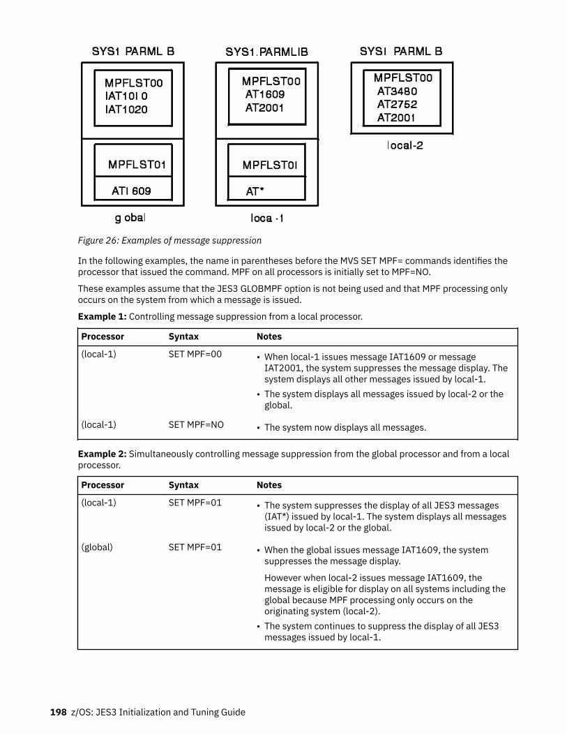
Figure 26: Examples of message suppression
In the following examples, the name in parentheses before the MVS SET MPF= commands identifies theprocessor that issued the command. MPF on all processors is initially set to MPF=NO.
These examples assume that the JES3 GLOBMPF option is not being used and that MPF processing onlyoccurs on the system from which a message is issued.
Example 1: Controlling message suppression from a local processor.
Processor Syntax Notes
(local-1) SET MPF=00 • When local-1 issues message IAT1609 or messageIAT2001, the system suppresses the message display. Thesystem displays all other messages issued by local-1.
• The system displays all messages issued by local-2 or theglobal.
(local-1) SET MPF=NO • The system now displays all messages.
Example 2: Simultaneously controlling message suppression from the global processor and from a localprocessor.
Processor Syntax Notes
(local-1) SET MPF=01 • The system suppresses the display of all JES3 messages(IAT*) issued by local-1. The system displays all messagesissued by local-2 or the global.
(global) SET MPF=01 • When the global issues message IAT1609, the systemsuppresses the message display.
However when local-2 issues message IAT1609, themessage is eligible for display on all systems including theglobal because MPF processing only occurs on theoriginating system (local-2).
• The system continues to suppress the display of all JES3messages issued by local-1.
198 z/OS: JES3 Initialization and Tuning Guide
Processor Syntax Notes
(local-1) SET MPF=NO • When the global issues message IAT1609, the systemsuppresses the message display.
However, when local-1 or local-2 issues message IAT1609,the message is eligible for display on all systems includingthe global. The system displays all other messages.
(global) SET MPF=NO • The system now displays all messages issued by allprocessors.
Example 3: Suppressing the display of a different set of messages at different times.
Processor Syntax Notes
(local-1) SET MPF=01 • The system suppresses the display of all JES3 messages(IAT*) issued by local-1.
• The system displays all messages issued by the global or bylocal-2.
(local-1) SET MPF=NO • The system now displays all messages.
(local-1) SET MPF=00 • When local-1 issues messages IAT1609 or IAT2001, thesystem suppresses the message display. The systemdisplays all other messages issued by local-1.
• The system displays all messages issued by the global or bylocal-2.
Using MPF to Screen Messages for Automation
Use MPF to specify which messages you want eligible for processing by an automation package. You canimprove the performance of your automated operations and prevent bottlenecks by sending to yourautomation program only those messages that you've identified for automation.
Use the AUTO parameter on the MPF msgid, .DEFAULT, or .NO_ENTRY control statements to controlwhich messages you want sent to your automation subsystem. For specific information and examplesabout using these control statements, see z/OS MVS Initialization and Tuning Guide. The contents of anMPFLSTxx member that controls which messages are sent to an automation program might be as follows:
.NO_ENTRY,AUTO(NO)
.DEFAULT,AUTO(YES)IAT9191IAT1600IAT2000,AUTO(NO)IAT2002
In the above example, messages IAT9191, IAT1600, and IAT2002 will be suppressed from consoledisplay and sent to the automation subsystem. MPF will suppress IAT2000 but not send it to theautomation subsystem. MPF will prevent all other messages from being sent to the automationsubsystem.
The use of the AUTO parameter does not affect whether messages are suppressed from console displays.You must specify message suppression independently of the automation option.
Automating message processingYou can automate the processing of messages in your JES3 installation by installing an automationproduct, which you can use to automatically respond to action or informational messages issued by JES3,MVS or application programs. You can also suppress the display of unsolicited messages that you select
Defining Consoles and Message Routing 199

for automation. Unsolicited messages are all messages except those that a program issues in response tocommands.
How to reduce message traffic using MPF
Use the MVS Message Processing Facility (MPF) to suppress the display messages that you have definedfor automation. See “Suppressing the Display of Messages” on page 196 or see z/OS MVS Initializationand Tuning Guide for information about using MPF.
Order of Command Execution
Many factors control the order of command execution. JES3 cannot guarantee the order in whichcommands are executed for the following reasons:
• Multiple commands entered through a single command issuance (eg. stacked) will be parsed from theend until a command delimiter (eg. semi-colon) is found and re-issued to be processed by automationand MPF/message exits individually.
• JES3 FCT dispatching priorities will cause some commands to be executed before others.• Console appendages written for each Dynamic Support Program (DSP) may process commands in any
order.• Multiple FCTs may exist to process a certain type of command; this affects the order commands are
executed. For example, multiple MODOSFCT FCTs can be active at the same time processing *MODIFY,Ucommands occurs.
• JES3 or MVS command exit processing may affect the time any single command takes to execute.• Depending on if any JES3 spool I/O is required to process the command will affect the time any single
command takes to execute. Many JES3 commands result in calls to the Work-To-Do-Driver (WTDDRVR)FCT, which processes commands which require JES3 spool I/O.
• Long running commands based on job queue searches and JES3 spool I/O which may be necessary toaccess job information should not delay other critical JES3 command processing.
• Non-JES3 commands processed by MVS or other subsystems will execute under other programsbeyond JES3's control. JES3 is not designed to synchronize the order of command execution betweenJES3 and non-JES3 commands.
IBM recommends that customers use message-based automation (for example, MPF command exits) iffeasible, or use automation to setup time delays as appropriate between critical commands, wheneverorder of command execution is important to their operations. In these cases, automation should be usedto ensure any single command has finished execution before issuing the next command in any criticalsequence.
200 z/OS: JES3 Initialization and Tuning Guide

Chapter 8. Defining and Managing JES3 Resources
You are responsible for defining and allocating resources for JES3. Resources include data sets, libraries,catalogs, devices, processors, volumes, and main storage. To define and allocate resources use JES3initialization statements and the JES3 cataloged procedure.
For a discussion about defining and managing mains and storage, see Chapter 9, “Defining and managingJES3 mains and storage,” on page 237.
JES3 Data SetsBefore starting JES3, you must allocate space for the JES3 job library and for the spool data sets.Optionally, you can define spool partitions and specify how you want JES3 to use these partitions. Chapter6, “Defining and Managing Spool Data Sets,” on page 159 explains the many considerations for definingand managing spool data sets.
You can improve JES3 performance by identifying data sets that are resident on all systems. By knowingthe location of data sets, JES3 will not have to search for them. You can also improve performance by theway you configure system catalogs.
You should mark JES3 data sets as unmovable (DSORG=PSU on the DCB parameter of the DD statement).JES3 data sets are physical, sequential, and contain location-dependent information.
Allocating JES3 Data SetsThere are two ways to allocate most JES3 data sets: include a DD statement for the data set in the JES3cataloged procedure or dynamically allocate the data set by including a DYNALLOC statement in the JES3initialization stream. You should ensure that a dynamically allocated data set is accessible to allprocessors in the JES3 complex. If a dynamically allocated data set is unavailable to one or moreprocessors, operator intervention will be required during JES3 initialization. You cannot dynamicallyallocate dummy data sets, data sets cataloged in a private catalog, data sets required for a C/I FSSaddress space, or data sets defined by the ddnames:
• STEPLIB• CHKPNT or CHKPNT2• JES3IN
If you dynamically allocate a data set, do not include a DD statement for that data set. JES3 assigns adisposition of SHR to dynamically allocated data sets.
The JES3 global dynamically allocates all of the data sets specified on the DYNALLOC initializationstatement. The JES3 locals dynamically allocate the following subset of data sets specified on theDYNALLOC statements:
• JES3JCT (JCT data set)• JESABEND• SYSABEND• SYSUDUMP
If a local processor becomes the global processor through dynamic system interchange (DSI), JES3dynamically allocates the remaining DYNALLOC statements:
• IATPLBxx (procedure library data sets)• JES3DRDS (disk reader data set)• JES3SNAP• Any user data sets
© Copyright IBM Corp. 1988, 2017 201

Allocating the JES3 Checkpoint Data SetsThe JES3 checkpoint data set(s) let(s) you warm start or hot start the JES3 system with little or no loss ofsystem information.
One or both JES3 checkpoint data sets must be defined in the JES3 start procedure using ddnames ofCHKPNT, CHKPNT2, or both. If your installation defines any C/I FSS address spaces, define the JES3checkpoint data set(s) in the C/I FSS start procedure exactly as the JES3 start procedure defines them. Tosee the IBM-supplied C/I FSS start procedure, see “Defining a C/I FSS address space” on page 143, inChapter 5, “Defining and managing C/I service,” on page 141. You cannot dynamically allocate thecheckpoint data sets. You must allocate and catalog one or both checkpoint data sets before JES3operation.
At least one of the checkpoint data sets must be available to JES3 during initialization processing. You canadd or replace either checkpoint data set over a JES3 restart of any kind with no effect on JES3processing. Both checkpoint data sets contain identical information; to ensure against loss ofcheckpointed data, allocate both data sets.
Note: If you allocate only one checkpoint data set and it develops a severe permanent I/O error, you mustperform a cold start. If you allocate both checkpoint data sets and one develops a severe permanent I/Oerror, JES3 can continue. For recovery procedures, see z/OS JES3 Diagnosis.
Unless you take special action, each checkpoint data set will not have extended attributes and will not beEAS-eligible. To create a data set with extended attributes that is EAS-eligible, code the EATTR=OPTkeyword on the JCL DD statement that is used to create the data set; then the data set can exist in theExtended Addressing Space (EAS) of an Extended Address Volume (EAV).
Creating or using a data set with extended attributes requires z/OS V1R12 or later releases. A data setwith extended attributes and residing in the EAS cannot be opened on earlier-level systems.
Determining the Size and Placement of the Checkpoint Data Sets
Each checkpoint data set must be allocated as a single extent which begins and ends on a cylinderboundary. The size of each checkpoint data set should be at least two cylinders on a direct access storagedevice. To determine how much space your installation's checkpoint data sets require, consider thefollowing factors:
• Each checkpoint record type begins on a track boundary. Each track contains a 128-byte track headerrecord.
• The checkpoint data set track map, the complex status record, the initialization checkpoint record, andthe JESCKPNT checkpoint record each need one track.
• The dynamic allocation checkpoint record requires 44 bytes plus an additional 92 bytes for eachDYNALLOC initialization statement.
• The spool volumes checkpoint record requires 64 bytes plus an additional 80 bytes for each TRACK andFORMAT initialization statement. Add additional bytes as reserve for spool expansion.
• The spool partition checkpoint record requires 64 bytes plus an additional 96 bytes for each SPARTinitialization statement.
• The partition TAT checkpoint record space requirement is calculated using a complex algorithminvolving many different factors. Allow about 512 bytes for each spool data set.
• The BADTRACK checkpoint record requires 44 bytes plus an additional 64 bytes for each BADTRACKinitialization statement. Every entry in the BADTRACK checkpoint record requires an additional 64bytes. Thus, the size of this data area varies with the number of tracks having I/O errors at one time.
• Allocate enough free space to permit growth in the complex without reallocating the checkpoint datasets. Checkpoint data sets are limited to 65,535 tracks.
If either checkpoint data set runs out of space, the data set must be replaced. Recalculate the amount ofspace the checkpoint data set needs and allocate a new checkpoint data set that is larger than the oldone.
202 z/OS: JES3 Initialization and Tuning Guide

To minimize the effect of the loss of any one DASD volume, control unit, or channel path, allocate thecheckpoint data sets on different volumes, channel paths, and control units. The volumes may bedifferent device types.
Replacing or moving the JES3 checkpoint
The JES3 checkpoint (one or two data sets) is defined by a DD statement in the JES3 procedure library.Replacing or moving the JES3 checkpoint might be necessary if initialization is not successful or ifreplacing a DASD storage device is required. Use the following procedure to replace or move the JES3checkpoint:
• Begin the process by identifying the one or two active checkpoint data sets. One of them must containthe current checkpoint data.
• Create a new, additional checkpoint data set on an alternate DASD storage device. Use the same sizeand DCB that are used by the current checkpoint data set.
• Update the JES3 procedure and the JES3 CI task JCL in the proclib with the new checkpoint data setname.
• Shut down the local processors.• Shut down the global processors.• Do a hot start with refresh on the global processor.• Start JES3 on the local processors.
The JES3 restart identifies and uses the new JES3 checkpoint data set.
Defining the Maximum Number of Jobs for Your ComplexYou can allow as many as 999,999 jobs to exist in your JES3 complex at the same time. However, JES3limits the maximum number of jobs that can be active concurrently by choosing the smallest of thefollowing:
• The value you specify on the job limit parameter on the JOBNO= keyword of the OPTIONS initializationstatement
• The range of job numbers that you define on the JOBNO= keyword of the OPTIONS initializationstatement
• The number of entries in the job control table (JCT)
Use the JOBNO= keyword of the OPTIONS initialization statement to specify the maximum number ofjobs for your system.
Controlling the Number of Jobs Allowed in a JES3 Complex:
The number of jobs concurrently allowed in a JES3 complex depends on the size of the JCT data set andJOBNO= keyword parameters specified on the OPTIONS statement in the JES3 initialization. The JOBNO=keyword has the following format.
OPTIONS,JOBNO=(low_job_number,high_job_number,max_number_jobs)
The job number range is specified by low_job_number and high_job_number values. The number ofconcurrent jobs allowed in the JES3 complex is the minimum of the following values:
• Number of records in the JCT data set• Maximum number of jobs from the JOBNO= keyword• Difference between low and high job numbers from the JOBNO= keyword
By specifying the OPTIONS initialization statement and the keyword JOBNO=, you can control the numberof jobs in the JES3 complex. Below is a progressive example showing how you can decide on this number.
Defining and Managing JES3 Resources 203

• To allow the entire range of job numbers from 1 to 32767 to be assigned to jobs, but limit the maximumnumber jobs allowed in the system to 10000, you specify the following:
OPTIONS,JOBNO=(1,32767,10000)
• To increase the range of job numbers assigned to the maximum. You do a JES3 warm start or hot startwith refresh with the following specification:
OPTIONS,JOBNO=(1,999999,10000)
Note: The number of jobs allowed in the system has not increased, but the reuse of job numbersdecreases in frequency.
• To support 25000 JCT entries, you allocate a JCT large enough to hold 25000 entries, raise the numberof jobs allowed in the system to a number less than 25000 (ex: 15000) and increase the job numberrange to the maximum. You do a JES3 warm start or hot start with refresh with the followingspecification:
OPTIONS,JOBNO=(1,999999,15000)
• To support 40000 concurrent job in the system, you must increase the size of the JCT to be largeenough to support 40000 jobs. You can cold start to use the larger JCT data set, in which case you mustsave jobs currently on JES3 spool and restore the jobs after the cold start, or you can avoid the coldstart by running the IATUTJCT utility.
Reasons for Increasing the Number of Jobs in Your Complex
There are many reasons for increasing how many job numbers JES3 can process in a complex. Thefollowing discussion illustrates various installation reasons for increasing job numbers along withsolutions.Reason 1a
The number of jobs in the JES3 complex is currently limited by the size of the JCT data set. You do notneed to support a larger number of jobs concurrently in the complex, but would like to increase thejob number range.
Solution 1aIncrease the job number range by performing a JES3 warm start or hot start with refresh with anupdated JES3 initialization stream. For example, if you your "old" values span job number values from1 to 30000, and you want to increase the range from 1 to 55000, you update the your initializationstream as follows:
Current Initialization Stream:
OPTIONS,JOBNO=(1,30000),
New Initialization Stream:
OPTIONS,JOBNO=(1,55000),
Note:
1. Do not change to a job number range that does not include the current job number range. Jobswith numbers not in the new range will be discarded. During the warm start or hot start withrefresh, JES3 prompts the operator for each and every job whose current job number is not in thenew job number range. Furthermore, for each of these lost jobs that was active on the main, theprocessor that the job was running on must be IPLed.
2. JES3 saves 100 job numbers and 64 JCT entries for situations involving job number exhaustionand certain error recovery situations. The effective job number range is reduced by 164 andtherefore the JES3 job number range should be at least 300.
204 z/OS: JES3 Initialization and Tuning Guide

Reason 1bThe number of jobs in the JES3 complex is currently limited by the third parameter on the JOBNOkeyword, not the size of the JCT data set. You do not need to support a larger number of jobsconcurrently in the complex but would like to increase the job number range.
Solution 1bIncrease the job number range by performing a JES3 warm start or hot start with refresh with theJES3 initialization stream updated as follows.
Current Initialization Stream:
OPTIONS,JOBNO=(1,20000,10000),
New Initialization Stream:
OPTIONS,JOBNO=(1,30000,10000),
The same rules apply for the job number range overlaps as in Situation 1a. The maximum number ofjobs allowed in the system is controlled by the third JOBNO= keyword value.
Reason 2The current JCT data set contains 999999 JCT entries (or some number that is adequate to meet theinstallation's needs), and you would like to increase the job number range and the number of jobsallowed in complex.
Solution 2This is similar to Reason 1b. You only need to change the initialization stream to allow an increasednumber of job numbers to be used and to increase the concurrent number of jobs in the JES3complex. You then perform a JES3 warm start or hot start with refresh with the OPTIONS statementupdated to set the job number range appropriately. For example,
Current Initialization Stream:
OPTIONS,JOBNO=(1,30000,10000),
New Initialization Stream:
OPTIONS,JOBNO=(1,65000,65000),
Reason 3a:The current JCT data set is not large enough to contain the number of required JCT entries(concurrent jobs on the spool), and you would like to increase the job number range and the numberof jobs allowed in complex. A cold start of the JES3 complex is acceptable.
Solution 3aTo increase the concurrent number of jobs and the job number range, you must replace the JCT dataset with one of sufficient size to accommodate the required number of concurrent jobs. You thenchange the OPTIONS initialization statement to allow an increased range and number of jobs.
1. Dump the jobs on spool to tape using the DUMP JOB (DJ) utility. See z/OS JES3 Commands for theinformation on using DUMP JOB.
Note: This invocation of DUMP JOB does not involve translation as the spool control blocks arecompatible. (You will not have to specify TRANS=YES on the *CALL,DJ command.)
2. Allocate a new JES3 JCT data set of the appropriate size. See “Determining the size of the JCT dataset” on page 206 to determine the size of the data set to be allocated for the new JCT data set.
Note: When allocating a new JCT data set, the allocation must be in cylinders and as a singleextent data set.
3. Update the cataloged JES3 start procedure or the JES3 initialization stream to point to the newJCT data set.
4. Restart the JES3 complex with a COLD START.
Defining and Managing JES3 Resources 205

Note: No reformat of the spool data sets is necessary with this cold start. If the spool data sets aredefined with a TRACK statement, they are not formatted. (When JES3 formats the spool data sets,it does so one data set at a time, which can be a lengthy process.)
5. Use the DUMP JOB utility to reload the jobs to spool (unless Step #1 was omitted).
Using DUMP JOB to unload and reload the JES3 spool allows you to have a new job number range thatdoes not include the old job number range. When jobs are reloaded to spool, the old job number is beused if available otherwise a new job number is assigned. Unlike Reasons 1 and 2, there is no need forthe new job number range to include the old job number range.
Reason 3bThe current JCT data set is not large enough to contain the number of required JCT entries(concurrent jobs on spool) and you would like to increase the job number range and the number ofjobs allowed in complex. A cold start of the JES3 complex is NOT acceptable.
Solution 3bCreate a new JCT data set large enough for the required number of concurrent jobs and change theOPTIONS initialization statement to allow for an increase in the job range or number of jobs, whileincluding the current job number range. Run IATUTJCT to copy the contents of the current JCT dataset to the new one, change the JES3 procedure to point to the new JCT data set, and perform a warmstart or hot start with refresh with the new job number range.
Determining the size of the JCT data set
The JCT data set contains information about the status of jobs in the system. You must make the size ofthe JCT data set large enough to accommodate the maximum number of jobs that can be in your JES3complex simultaneously. If the data set is larger than required, JES3 uses only that portion needed tohold the maximum number of jobs (the remainder of the JCT is used for write error recovery). However,the larger the JCT data set, the longer JES3 initialization takes. For optimum performance, minimize thesize of the JCT data set as much as possible.
1. Calculate the size, in bytes, of the JCT entry within the JCT data set:
xxx= (4 x max SEs) + zzz + 28 bytes (prefix)
where:
• xxx is the size, in bytes, of a single JCT.• 4 is the size of one JCT scheduler element in the JCT.• Max SEs is the maximum number of scheduler elements as specified on the SE parameter of the
OPTIONS initialization statement (10 through 90 is the valid range - 10 is the default).• zzz is the size, in bytes, of the fixed JCT. Field JCTFSIZE in the IATYJCT macro defines this value. If
you have modified the size of your JCT by making changes to IATYJCT, IATYCNDB or IATYFDB, usethe value (from an assembled listing) in JCTFSIZE as the zzz value in the formula. If you have notmodified the size of the JCT, the value of JCTFSIZE is 668 bytes.
• 28 is the size, in bytes, of the SRF header prefix mapped when using the IATYSRF macro.2. Determine the number of JCTs per cylinder. For IBM 3380 and 3390 devices, use the following
documents to determine the number of JCTs that will fit on a track and cylinder:
• Using IBM 3390 Direct Access Storage in an MVS Environment• 3380 Direct Access Storage Introduction
Each document contains a table matrix in an appendix that shows how many physical blocks fit on atrack and a cylinder for various block sizes (because the JCT records are unblocked, the logical recordsize IS the block size).
Note: JCT records are without keys. A portion of the information from Using IBM 3390 Direct AccessStorage in an MVS Environment , Appendix B - Figure 71 "Records without Keys" is relevant to JCTrecords and is included below:
206 z/OS: JES3 Initialization and Tuning Guide

Table 42: Physical blocks per track and cylinder.
Data Length Range Percent Max Track Capacity (*) Max Cylinder Capacity (*)
Min Max Used (*) Records Bytes Records Bytes
1019 1086 63.2 33 35838 495 537570
985 1018 61.1 34 34612 510 519180
951 984 60.8 35 34440 525 516600
889 950 60.4 36 34200 540 513000
855 888 58.0 37 32856 555 492840
821 854 57.3 38 32452 570 486780
787 820 56.4 39 31980 585 479700
753 786 55.5 40 31440 600 471600
719 752 54.4 41 30832 615 462480
691 718 53.2 42 30156 630 452340
657 690 52.4 43 29670 645 445050
623 656 50.9 44 28864 660 432960
589 622 49.4 45 27990 675 419850
Note: (*) Calculations are made using the maximum size record in a range.
The column "Maximum Track Capacity Records" will give how many JCTs per track a 3390 cancontain.
The column "Maximum Cylinder Capacity Records" will give how many JCTs per cylinder a 3390can contain.
The size ranges shown in this table will cover most of the likely JCT record sizes. For other JCT sizes,3380 DASD, and other devices, consult the appropriate documents.
3. Determine the required size of the JCT data set:
JCT data set (64 + max # of jobs) size = ----------------------------in cylinders number of JCTs per cylinder
where:
• The JCT data set size in cylinders must be incremented to the next whole number if the result is nota whole number.
• 64 is the number of JCTs JES3 reserves for write error recovery.• The max # of jobs is the maximum number of jobs that can simultaneously be in your JES3 complex.• The number of JCTs per cylinder (as explained in the device specific table - of step #2 above).
Note:
1. JES3 reserves 64 or more JCT records in the JCT data set for "write" error recovery unless the numberof records in the JCT data set is less than or equal to 64. If your JCT contains 64000 records and youspecify JOBNO=(1,64000, 64000) on the OPTIONS statement, the number of jobs in the system islimited to 64000 - 64 = 63936. If you wanted to have 64,000 jobs in the system and specifiedJOBNO=(1, 64000,64000), the JCT data set would have to contain 64064 records to allow for the 64records needed for "write" error recovery. On the other hand, if your JCT contains 64000 records andyou specify JOBNO=(1,63000,63000) on the OPTIONS statement, the job number range is limited to63000, and 1000 JCT records are reserved for "write" error recovery (64000 - 63000 = 1000).
Defining and Managing JES3 Resources 207

2. The JCT data set should be allocated on a cylinder boundary.3. In order to change the size or placement of the JCT data set, you must either perform a cold start or
use the IATUTJCT utility. See “JCT Utility (IATUTJCT)” on page 210 for more information on changingyour JCT data set.
4. If you have not modified the length of the JCT by changes to IATYJCT, IATYCNDB, or IATYFDB, and youuse the default number of SE entries (10), then a JCT entry is 736 bytes long.
• 38 entries per track or 570 entries per cylinder on a 3380 device• 41 entries per track or 615 entries per cylinder on a 3390 device
5. The JCT data set can be greater than 65,535 tracks only if you specify the DSNTYPE=LARGE keywordon the JCL DD statement that is used to create the data set.
• Creating or using a large format data set requires z/OS V1R7 or later. The large format data setcannot be opened on earlier-level systems.
6. Unless you take special action, a JCT data set will not have extended attributes and will not be EAS-eligible. To create a data set with extended attributes that is EAS-eligible, code the EATTR=OPTkeyword on the JCL DD statement that is used to create the data set; then the data set can exist in theExtended Addressing Space (EAS) of an Extended Address Volume (EAV).
• Creating or using a data set with extended attributes requires z/OS V1R12 or later. A data set withextended attributes and residing in the EAS cannot be opened on earlier-level systems.
Example
You want to process 20,000 JES3 jobs concurrently. The size of the standard IBM-supplied JCT has notbeen modified by making changes to IATYJCT, IATYCNDB, or IATYFDB. You have specified SE=15 in theOPTIONS initialization statement, and are using IBM 3390 Direct Access Devices for the JCT data set:
1. Calculate the size, in bytes, of the JCT entry within the JCT data set:
xxx= (4 x max SEs) + zzz + 28 bytes (prefix)756= (4 x 15) + 668 + 28
2. Determine the number of JCTs per cylinder:
Using the 3390 capacity table above, a 756 byte record falls within the 753 - 786 data length range,and 600 of these records will fit in a 3390 cylinder.
3. Determine the required size of the JCT data set:
JCT data set (64 + max # of jobs) size = ----------------------------in cylinders number of JCTs per cylinder
33.44 = (64 + 20,000) / 600
Since the result is not a whole number, it must be incremented to the next whole number, 34.
Conclusion
You require a JCT data set size of 34 cylinders.
You can allocate the JCT data set by including the //JES3JCT DD statement in the JES3 cataloged startprocedure or by using a DYNALLOC initialization statement (see Figure 1 on page 4 for a sample of theJES3 cataloged procedure).
Using Performance Measurement Tools to Tune JCT Access
During initialization, JES3 places a copy of the JES3JCT data set on both JES3 spool and into the JCT dataspace. A data space is a range of up to 2 gigabytes of contiguous virtual storage. Unlike an address space,a data space can hold only data; it does not allow code to execute. See z/OS MVS Programming: ExtendedAddressability Guide for a description of data spaces and information about how to use them.
208 z/OS: JES3 Initialization and Tuning Guide

During normal operation, JES3 updates the JCT in the data space and on spool. However, the data spaceis subject to paging and MVS may migrate portions of the JCT to MVS paging data sets.
Excessive paging of the JCT data space can impact JES3 performance because JES3 must wait while MVSmoves pages of the JCT back into central storage. JES3 may also have to wait additional time if MVS isservicing other paging requests ahead of JES3's.
You can optimize performance and avoid performance bottlenecks by minimizing the amount of time itstakes JES3 to read the JCT. Use the following formula to determine the amount of time it takes to read theJCT in your installation:
(5 * x) * ((1 + (y * .5)) * 25) = Milliseconds to read JCT
where:
• ‘x’ represents the percentage of time that a JCT page was not in central storage during a read request.See the JQE/JCT Access Method Report section of your JMF report to determine the percentage oftime a page was not in central storage for a read request.
• ‘y’ represents the average number of page requests queued ahead of a JCT page request. See theSystem Paging Space Data portion of your RMF report to determine the average number of pagerequests queued.
The total amount of time required to read the JCT for each job should not exceed 125 milliseconds. Youcan take the following actions to reduce JCT access time:
• Reduce the JES3 paging rate.• Increase the amount of central or expanded storage.• Install additional paging devices to reduce I/O contention.• Use SRM storage isolation for the JES3 address space. See z/OS MVS Initialization and Tuning Guide for
information about how to use storage isolation.• Increase the intervals at which a changed or unchanged page that is to be paged out will be sent to
expanded storage. Use the ESCTPOC and ESCTPOU keywords in the IEAOPTxx member of the MVSSYS1.PARMLIB data set to modify these intervals. See z/OS MVS Initialization and Tuning Guide forinformation about updating the MVS SYS1.PARMLIB data set.
The acceptable percentage of read page faults varies from installation to installation. Use the followingformula to determine an acceptable percentage of JCT read page faults for your installation:
125------------------------- = Acceptable % of read page faults((1 + (y * .5)) * 25) * 5
Use the JQE/JCT Access Method Report section of your JMF report to determine the percentage of timethat a page was not in central storage for a read request. See z/OS JES3 Diagnosis for an example of a JMFreport.
Note:
1. The percentage of read requests when a page is not in central storage does not always imply that MVShas migrated the page to an external storage device. The value also includes page faults where pagesmay have been migrated to expanded storage.
2. If you use storage isolation to reduce paging, SRM considers the JCT data space as part of the JES3working set and may increase the working set size. See the JES3 Working Set Size section of yourJMF report to determine the amount of virtual storage that JES3 uses in your installation. If the JES3paging rate increases after the JCT data space is enabled, consider increasing the JES3 working setsize or adding additional central or expanded storage.
3. The percentage of time that the JCT is not in central storage for a write request should be very small.The largest user of the JCT is the job segment scheduler (JSS) which reads the JCT, performs a smallamount of I/O, and writes the JCT to spool. A high percentage would indicate more serious problems,such as an unacceptable paging rate.
Defining and Managing JES3 Resources 209

4. Storage fragmentation and excessive JES3 storage requirements can cause excessive paging of theJES3 address space. You can obtain the paging rate for your installation using the JES3 Paging CountsDuring JMF Monitoring portion of your JMF report. If your paging rate is very high, consider thefollowing actions:
• Reduce the size of the console buffer text pool using the CONSBUF= keyword of the JES3 CONSTDinitialization statement.
• Reduce the size of the JSAM buffer pool using the PAGES= keyword on the JES3 BUFFERinitialization statement; however, make the size of the JSAM buffer pool large enough toaccommodate the amount of work in your system during peak periods.
• Release held output. Releasing held output allows JES3 to purge jobs, which can free large chunks ofstorage.
JCT Utility (IATUTJCT)
Introduction
For various reasons you might need to replace an existing JCT data set. In order to allow a JCT data set tobe copied without a cold start, JES3 provides a program called the JCT utility, or IATUTJCT.
IATUTJCT can be used to satisfy the following requirements:
• You need to allocate a larger JCT data set in order to provide capacity for more jobs in the JES3 jobqueue.
• You need to move your JCT data set to a new volume. The new volume can be the same device type asthe one where your JCT data set currently resides, or it can be a different one.
Because the contents of the JCT data set are dependent on the device type and the location of the JCTdata set on its volume, an existing JCT data set cannot be copied by a utility such as IEBGENER.Furthermore, there is information about the JCT data set in the checkpoint data set which cannot becopied.
IATUTJCT copies JCT entries from one JCT data set to another, and updates the device-dependentinformation at the same time. IATUTJCT also copies the JCT information that is kept in the checkpointdata set.
Copying a JCT Data Set Using the IATUTJCT Utility
To perform the copy using IATUTJCT, you must:
• Allocate a new set of checkpoint data sets in addition to the new JCT data set.• You must identify the data set names for the new data sets used in the JCL for the JCT utility.• Arrange your system such that JES3 can be started with either the new or old data sets. You can use
symbolic parameters on the JES3 procedure to allow use of either the new or old data sets.• Bring JES3 and all Converter Interpreter Functional Subsystems (CIFSS) down on the global processor
and all local processors.
CAUTION: If you do not bring JES3 down, JES3 might update the old JCT and the checkpointdata sets after you run IATUTJCT. These updates will be lost when you switch to the new datasets and will cause corruption to the JES3 job queue. This corruption then could lead toconditions from which a cold start is required to recover.
• Restart JES3, after running IATUTJCT, with the DD definitions that point to the new JCT data sets. Forthe checkpoint data set, these DD statements are in the JES3 procedure. For the JCT data set, these DDstatements are in the JES3 procedure or identified by the DYNALLOC statement in the JES3 initializationstream.
• Restart the C/I FSS procedures with the new checkpoint data sets.
210 z/OS: JES3 Initialization and Tuning Guide

Running the IATUTJCT Utility
You run IATUTJCT by invoking a started task that runs the IATUTJCT program. Below is a sample JCLprocedure you might use to run IATUTJCT. Such a JCL procedure must be in SYS1.PROCLIB. MemberIATUTJCS of the OS/390 SIATSAMP data set also provides a sample JCL procedure for IATUTJCT.IATUTJCT must be started using SUB=MSTR.
//IATUTJCT PROC P=//*//IEFPROC EXEC PGM=IATUTJCT, Invoke the IATUTJCT Utility// TIME=1440,// PARM='&P'//*//STEPLIB DD DISP=SHR, Required if IATGRCK and IATUTJCT// DSN=SYS1.SIATLIB are not in LNKLSTxx//*//JES3JCT DD DISP=SHR, Current JCT data set// DSN=SYS1.JES3JCT//*//NJES3JCT DD DISP=SHR, New JCT data set// DSN=SYS1.NJES3JCT//*//CHKPNT DD DISP=SHR, Current primary checkpoint data set// DSN=SYS1.CHKPNT//*//CHKPNT2 DD DISP=SHR, Current alternate checkpoint data set// DSN=SYS1.CHKPNT2//*//NCHKPNT DD DISP=SHR, New primary checkpoint data set// DSN=SYS1.NCHKPNT//*
Figure 27: Sample JCL for IATUTJCT Utility
Setup and Initialization Considerations
• When using IATUTJCT to move the JCT data set, you can pick up the new data set with any type of JES3start; however, if you perform a hot start with refresh or a warm start, and you use the DYNALLOCstatement to define the JES3JCT DD name, you must change the DYNALLOC statement to point to thenew JCT data set.
• The JES3 installation must properly meet specific programming requirements for using IATUTJCT.
– Place the load library containing IATUTJCT and IATGRCK in the LNKLST concatenation or ensure theyare in STEPLIB. JES3 must find these load modules in a normal library search.
OS/390, by default, places modules IATUTJCT and IATGRCK in SYS1.VnRnMn.SIATLIB.– Ensure that the library containing the IATUTJCT and IATGRCK modules is APF authorized.– Ensure that the JES3JCT, NJES3JCT, CHKPNT, and NCHKPNT DD statements are specified. The
CHKPNT2 DD statement is optional and should be omitted if you are not using an alternatecheckpoint data set or if you will not be using one after changing JES3 to use the new data sets.
– Ensure that proper CHKPNT and CHKPNT2 DD statements are specified. There is no NCHKPNT2 DDstatement. If you are using an alternate checkpoint data set, allocate a new one and leave it empty.When you restart JES3 to pick up the new primary and alternate checkpoint data sets, JES3 willautomatically synchronize the new alternate checkpoint data set to the new primary checkpoint dataset. Do not use the old alternate checkpoint data set as the new alternate checkpoint data set.
– The PROC statement in the procedure must define the P= keyword parameter. This parametercontrols the migration of a JCT data set from a lower version to a higher version in preparation forinstalling a new release of JES3 that requires the higher version.
Defining and Managing JES3 Resources 211

Use Considerations
• If you are migrating your JCT data set in preparation for the installation of a higher release of JES3, see“Migrating Using IATUTJCT” on page 214 for information performing this migration.
• Allocate your new JCT data set and primary checkpoint data sets, and (optionally) your new alternatecheckpoint data set. In doing this:
– Be certain to allocate these data sets in cylinders with only one extent.– Be certain that your new JCT data set is large enough for your planned job number range, plus 64
spare JCT entries needed for write-error recovery. See “Determining the size of the JCT data set” onpage 206 for information on calculating the size of the JCT.
Note:
1. If you migrate the JCT data set from a "lower version" to a "higher version", you must allocate alarger JCT data set to accommodate the same number of jobs because the JCT entry size in the"higher version" is larger.
2. Your new JCT data set can be smaller than your old JCT data set if the JCT contains sufficient jobcapacity for the job number range on the options initialization statement. If you discover later thatyou need more capacity, you will then have to allocate a larger JCT data set and run IATUTJCTagain.
• In JES3 installations where SYS1.PROCLIB is not shared, install the IATUTJCT procedure separately onany processor where IATUTJCT is to run.
• Define the procedure to the security product.
– Define either a profile for the started task in the STARTED security class or an entry in the started tasktable (ICHRIN03).
– Provide the userid under which the procedure is to run with at least read access to the old JCT andcheckpoint data sets and update access to the new JCT and primary checkpoint data set.
Note:
1. If your processors do not share the security product's data base and the STARTED security class isused to define IATUTJCT's security environment, define the STARTED class identically on anyprocessor where IATUTJCT is to run.
2. If you use the started task table to define IATUTJCT's security environment, define the entry for thestarted task table identically on any processor where IATUTJCT is to run.
• Either change the JES3 start-up procedure in SYS1.PROCLIB to allow names of your checkpoint datasets (and JCT data set, if not defined by the DYNALLOC initialization statement) to be specified assymbols, or install a new JES3 procedure in SYS1.PROCLIB to point to the new data sets.
For a new start-up procedure:
– Define an entry in the STARTED security class or an entry in the started task table (ICHRIN03)– Create a new SYS1.PARMLIB(IEFSSNxx) member pointing to the new name of the procedure you are
creating as a subsystem with the PRIMARY attribute.• If you use the DYNALLOC statement to define the JES3JCT DD name, create a new initialization stream
member that points to the new JCT data set.• If you want to test IATUTJCT, you can start it with JES3 up or down.
Note: You might want to test IATUTJCT in order to make sure that the new data sets are acceptable andthat the new JCT data set is large enough to contain all the jobs from the old JCT data set plus 64 spareJCT entries for error recovery.
See “Testing IATUTJCT Processing” on page 213 for more testing information.• When you are ready to copy the checkpoint and JCT data sets to the new ones you intend to use, stop
all CIFSS address spaces and bring JES3 down on the global processor and all local processors. If youhave any other started tasks or jobs that refer to the JCT or checkpoint data sets, such as user-writtenspool browsers, bring them down also.
212 z/OS: JES3 Initialization and Tuning Guide

• Start IATUTJCT with the SUB=MSTR parameter. If you are migrating from a "lower version" to a "higherversion," use the P=MIGRATE parameter. If you are falling back from a higher JES3 release to a lowerJES3 release, use the P=FALLBCK parameter. You need to run IATUTJCT only once in a JES3 complex,and you can run it on the global or any local processor.
S IATUTJCT,SUB=MSTR
Figure 28: IATUTJCT Utility Start Command
S IATUTJCT,P=MIGRATE,SUB=MSTR
Figure 29: IATUTJCT Utility Migrating Start Command
S IATUTJCT,P=FALLBCK,SUB=MSTR
Figure 30: IATUTJCT Utility Fallback Start Command
Note: No parameter value for P= other than MIGRATE or FALLBCK is allowed.• If IATUTJCT fails, or if you decide to not switch to the new data sets, you must restart JES3 with the old
data sets. You can perform a hot start, hot start with refresh, or IPL with a warm start. If you havechanged the initialization stream (the JES3JCT DYNALLOC statement to point to the new JCT data set)and you perform a hot start with refresh or a warm start, do not use the initialization stream membercontaining the change.
• If you defined an alternate JES3 procedure as a primary subsystem on the global, IPL the globalpointing to the new IEFSSNxx parameter.
• If IATUTJCT is successful, restart JES3 on the global pointing to the new data sets. You must beginusing the new checkpoint data sets and the new JCT data set at the same time. Do not mix old and newdata sets.
– If your JCT data set is dynamically allocated and you are changing its cataloged status from catalogedto uncataloged or from uncataloged to cataloged, you must perform a hot start with refresh or warmstart.
– If you perform a warm start or hot start with refresh and you define the JES3JCT DD using theDYNALLOC statement, you must use the initialization stream that you previously created, pointing tothe new JCT data set.
• All converter/interpreter (CIFSS) startup procedures must be updated to point to the new checkpointdata sets. Or, you could make new CIFSS procedures that point to the new checkpoint data sets andthen use the *MODIFY,F command to change the FSS to use the new procedure. Because a CIFSSstartup procedure cannot accept JCL symbolics, you must change the DD statements within theprocedure before restarting the CIFSS address spaces.
• If you defined an alternate JES3 procedure as a primary subsystem on the locals, IPL all locals pointingto the new IEFSSNxx member.
• Restart JES3 on all locals pointing to the new data sets.• Start all CIFSS procedures pointing to the new checkpoint data sets.• If you have any other started tasks or jobs that refer to the JCT or checkpoint data sets, such as user-
written spool browsers, change their data set references to the new JCT data set, and restart them atyour convenience.
• Rename or delete the old checkpoint and JCT data sets so that you do not accidentally use them again.When you have started using the new data sets, you must not revert to the old data sets. If you do, yourisk corruption of the JES3 job queue possibly leading to conditions from which a cold start is requiredto recover.
Testing IATUTJCT Processing
You can run the IATUTJCT utility as a test while JES3 is up and running. Do not change any definitions inthe JES3 startup procedure or CIFSS procedures.
Defining and Managing JES3 Resources 213

• If testing the migration from a lower version to a higher one, use the P=MIGRATE parameter.• If testing fallback from a higher JES3 release to a lower JES3 release, use the P=FALLBCK parameter.• You need to test IATUTJCT only once in a JES3 complex, and you can test it on the global or any local.• You do not need to specify SUB=MSTR parameter when testing IATUTJCT with JES3 up and running.
Migrating Using IATUTJCT
Special considerations for restarts apply if you are migrating between JES3 releases.
Identifying Resident Data SetsDuring JES3 initialization you can identify data sets that are resident on all systems. Thereafter, when thenames of these data sets appear as catalog references on a DD statement for a job, JES3 will bypasscatalog searches (also called LOCATE processing) during the postscan phase of C/I service. Thus, youimprove JES3 performance. To specify the names of the resident data sets, use the RESDSN initializationstatement.
JES3 does not perform data set integrity processing for resident data sets. Therefore, do not specify SMS-managed data sets as resident data sets unless the data set can be accessed from only one processor orunless the user provides data set integrity. MVS provides data set integrity when a resident data set canbe accessed from only one processor.
Using system catalogsYou can eliminate the need for a job to execute on a specific processor to satisfy a catalog dependency bysharing catalogs among all processors. To ensure that JES3 does not assume unnecessary processordependencies because of a catalog search, use the RESDSN statement to identify catalogs that areresident on all processors. MVS, not JES3, will then process references to these catalogs.
If the storage management subsystem (SMS) is not active and a job needs a catalog that is not availableto all processors, the user must ensure that the job executes on a processor that has access to thecatalog. The user can do this by specifying either the SYSTEM or SYSAFF parameter on the JOB controlstatement, the SYSTEM parameter on the //*MAIN control statement, or a job class that belongs to agroup that will execute on the appropriate processor. If SMS is active, no action is required to ensurecatalog availability. JES3 and SMS together determine the availability and connectivity of catalogs.
To prevent a catalog from being altered between the time JES3 accesses it while scheduling the job andthe time MVS accesses it while executing the job, the user should use dependent job control (DJC). In thisway, the user can ensure that the jobs will access the catalog in the correct sequence. For example, if jobA creates a catalog entry required by job B, the user should define job B as being dependent on job A.
If a job references a data set that is cataloged in a control volume catalog (CVOL), the operator mustmount the volume that contains the CVOL before JES3 can access the data set. JES3 fails any job thatrequires access to an unmounted CVOL. See Catalog Administrator's Guide for a complete description ofCVOLs and their uses.
If you are using the storage management subsystem, the master catalog must be an ICF catalog on allmains where C/I processing is performed. Ensure that all master catalogs contain alias names for all usercatalogs.
I/O DevicesYou must define to JES3 each I/O device that JES3 is to use or manage, except devices used for data setsdefined in the JES3 cataloged start procedure or defined using the DYNALLOC initialization statement.
Because JES3 varies assignable devices and all execution devices online to MVS and JES3 at initialization(based on the JUNIT or XUNIT parameter values), at least one path to those devices must be onlinebefore initializing JES3. Also, you must satisfy all conditions necessary for the MVS VARY command toexecute properly before initializing JES3. (For a discussion of assignable devices, see “JES3 Devices” onpage 215 below.)
214 z/OS: JES3 Initialization and Tuning Guide

Defining I/O Devices to JES3Before JES3 can use an I/O device, the device must be attached to the global processor or to a localprocessor and you must define it to JES3. To define a device to JES3, code a DEVICE initializationstatement.
The DEVICE statement specifies device characteristics and tells JES3 how to use that device. There arethree ways to define a device to JES3 using the device statement:
• You can specify that JES3 is to use a device to satisfy JES3 functions, such as DSP requests, inputprocessing, and output processing. This is called a JES3 device.
• You can specify that JES3 may allocate a device to MVS to execute user jobs. This is called an executiondevice.
An execution device that is defined to JES3 and MVS as permanently resident or reserved is called ajointly-managed device.
• You can specify that JES3 can use the device as either a JES3 device or as an execution device. This iscalled a shared device.
To simplify the task of adding or changing multiple devices, use the NUMDEV keyword and the processorname *ALL. Alternatively, you can use the IATDEVA and IATDEVC edit macros, which are documented inz/OS JES3 Customization.
JES3 cannot use restricted devices. Therefore, do not define a restricted device on a JES3 DEVICEinitialization statement.
JES3 Devices
To define a JES3 device, specify the DTYPE, JNAME, and JUNIT parameters on the DEVICE statement. Ifapplicable, you should also specify the DGROUP parameter and any printer or punch parameters.
JES3 devices must be attached to the global processor. The only exception is a device driven by an outputwriter functional subsystem (FSS), which you may define as a JES3 device and attach to the globalprocessor or a local processor.
Use unique device numbers for JES3 devices when you execute the MVS configuration program. When thesame device is attached to more than one processor, the device should have the same device number oneach processor. On the other hand, if different JES3 devices attached to different processors have thesame device number, JES3 considers the device number “ambiguous” because JES3 cannot alwaysdetermine which device is being requested. Therefore, JES3 may reject operator commands that refer tothe devices by device number. Operator commands for those devices must refer to them using the namespecified on the JNAME parameter of the DEVICE statement.
You can define as JES3 devices:
• Network lines• Printers• Card punches• Card readers• Remote terminals• Tape drives
An “assignable device” is a JES3 device such as a supported tape drive that JES3 can reserve using theMVS assign/unassign facility. When an assignable device is connected to more than one processor, theassign/unassign facility lets the operator use the *VARY command to reserve the device for one or moreprocessors within a JES3 complex. However, you must use the JES3 VARYL dynamic support program tounassign a supported tape drive when all of the following conditions exist:
• The global has failed
Defining and Managing JES3 Resources 215

• You want to use the tape drive to take a stand-alone dump• The tape drive is assigned to more than one main
For additional information about using the VARYL dynamic support program, see z/OS JES3 Commands.
Execution devices
To define an execution device, specify the XTYPE and XUNIT parameters on the DEVICE statement. Whenany execution device is initialized, JES3 varies the device online or offline to MVS and JES3 based on theXUNIT parameter specification. You can attach execution devices to the global processor or to any localprocessor.
Shared Devices
To define a device as a shared device, specify the DTYPE, JNAME, JUNIT, XTYPE, and XUNIT parameterson the DEVICE statement for that device. If applicable, you may also specify the DGROUP parameter andany printer or punch parameters.
Defining Process ModesDefining device process modes allows you to specify what types of data sets you can schedule to thatdevice. If a user specifies a data set process mode (specified on the OUTPUT JCL statement) thatmatches one of the process modes defined for a device, then JES3 can schedule that data set to thedevice. To define process modes for a device, specify the PM= keyword on the DEVICE initializationstatement. You can specify as many as eight process modes per device. Unless you modify the list ofprocess modes or the operating mode of the device using operator commands, the process modes thatyou define in your initialization stream remain in effect.
You can also define alternate process modes for some devices.
Note: You can define alternate process modes for certain devices, such as the 3800 Model 3 printer, thatmay run under the control of an output writer in the JES3 global address space or under the control of anoutput writer functional subsystem.
These process modes become effective only when you change the device operating mode (using anoperator command) from what was originally defined (or defaulted to) on the MODE= keyword of theDEVICE statement. In other words, you can switch between the initial set of process modes and analternate set.
Note: You can switch between sets of process modes using the *MODIFY,FSS,D= command.
To define alternate process modes for a device, specify the ALTPM= keyword on the DEVICE statement.You can specify as many as eight alternate process modes for a device.
Two values frequently defined on the PM= and ALTPM= keywords are LINE and PAGE. Specifying PM=LINEindicates that data sets assigned a process mode of ‘line’ in their JCL can be scheduled to this device.Under normal circumstances, these are line mode data sets, meaning that they are formatted line by line.Specifying PM=PAGE indicates that data sets assigned a process mode of ‘page’ in their JCL can bescheduled to this device. Again, these data sets normally are page mode data sets, meaning thoseformatted as a composed page.
Note: If PM=(PAGE,...) is specified for a device that does not support composed page formatting, or ‘all-points-addressable’ function as it is sometimes called, that device will select and attempt to print pagemode data sets with unpredictable results. Line mode data is printed normally.
Using Process Mode Defaults
Device modes and process modes are interdependent. If you change a printer's device mode, its processmode must be compatible (for example, you cannot print PAGE mode data when operating your printer inCOMP mode).
You can code the ALTPM= keyword on the DEVICE initialization statement to define which processmode(s) take effect when you change a printer's device mode.
216 z/OS: JES3 Initialization and Tuning Guide

If you do not define alternate process modes and you change a printer's device mode (from MODE=COMPto MODE=FSS or the reverse), JES3 uses default values shown on the following figures.
Table 43: Default Value(s) for ALTPM= When MODE=COMP
Initial process mode value Default process mode(s) thatJES3 uses if you switch to FSSmode
Process mode(s) that JES3 usesif you switch back to COMPmode
LINE (LINE,PAGE) LINE
PAGE (LINE,PAGE) PAGE
(LINE,PAGE) (LINE,PAGE) (LINE,PAGE)
Table 44: Default Values for ALTPM= When MODE=FSS
Initial process mode value Default process mode(s) thatJES3 uses if you switch toCOMP mode
Process mode(s) that JES3 usesif you switch back to FSS mode
LINE LINE LINE
PAGE LINE PAGE
(LINE,PAGE) LINE (LINE,PAGE)
Running a Printer Under an Output Writer Functional SubsystemSome printers run under the control of the JES3 global address space. Certain printers, such as AFPprinters, must run under the control of a non-JES3 address space called an output writer functionalsubsystem (FSS).
To use a PSF printer as a system output device, you must first do the following:
1. Define one or more PSF FSSs.2. Define FSAs for each PSF printer.3. Make sure that you have a startup procedure for each PSF FSS.
If your IP printway FSA's JES3 DEVICE initialization statement specifies DYNAMIC=YES and its WS criteriaincludes form, JES3 will not start the FSA dynamically unless a print data set's form attributes and otherattributes match the FSA's work selection criteria.
After you complete Steps 1 through 3, the operator can enter commands to start each FSA. JES starts theFSS automatically when the first FSA it controls is started. For more information on using PSF, see PrintServices Facility/MVS Customization Guide.
Defining PSF FSSs and FSAs for Printers
To use a PSF printer under JES, you must first code JES initialization statements to define PSF FSSs andFSAs for PSF printers. You use the FSSDEF initialization statement to define the FSS, and you use theDEVICE initialization statement to define each printer FSA. The following number of FSSs and FSAs aresupported:
• A maximum of 2000 FSSs• A maximum of 128 FSAs per FSS
Note: The actual number of FSAs per FSS depends on several factors, including:
• The virtual region size below the 16-megabyte line• The number and the size of form definitions and page definitions
Defining and Managing JES3 Resources 217

• The number of buffers specified for channel-attached printers• The block sizes of the font, page segment, overlay, form definition, and page definition libraries
See “Determining the Maximum Number of Printers for an Output Writer FSS” on page 219 for moredetail.
Printer specifications
You specify whether you want a printer to run under the control of the JES3 global address space or underthe control of an FSS by specifying the FSSNAME= and MODE=FSS keywords on the DEVICE initializationstatement. If you run a printer under the control of an FSS and you want to define the characteristics ofthat FSS, you must include an FSSDEF initialization statement. Otherwise, JES3 dynamically creates anFSS using default values.
The following sections describe how to define an output writer FSS and how to define specific AFPprinters (such as, 3900 and 3827 printers), to run under the control of an output writer FSS.
Defining an Output Writer Functional Subsystem
You can define one or more printers to run under the control of a single output writer FSS or you can allowJES3 to define a unique FSS for each printer by default.
You can also select the main on which you want an output writer FSS to operate by coding the SYSTEM=keyword on the FSSDEF initialization statement.
Perform the following steps to define one or more page printers to run under the control of an outputwriter FSS:
1. Attach the printer(s) you want to run in FSS mode to the main on which you plan to define the outputwriter FSS. The data processed by the printer(s) can originate from any main within your JES3 complexor at any node in a job entry network.
2. Define a cataloged procedure for starting the output writer FSS in SYS1.PROCLIB and specify the nameof the procedure on the PNAME= keyword of the FSSDEF initialization statement. To learn more aboutcataloged procedures and how to modify them, see Print Services Facility/MVS System Programmer'sGuide and Print Services Facility/MVS Customization Guide. Parameters that you define on JES3initialization statements override the corresponding parameters in a cataloged procedure. However,the PDEFAULT= parameter on the DEVICE (I/O) initialization statement can be used to direct JES3 tonot send the CHARS and FCB defaults to the FSS.
3. Include an FSSDEF statement in your initialization stream and name the FSS using the FSSNAME=keyword.
4. Include a DEVICE statement for each printer that you want to run under this FSS. You must include theFSSNAME= keyword on the DEVICE statement that specifies the same name that you code on theFSSNAME= keyword of the FSSDEF initialization statement.
5. Perform a hot start with refresh, warm start, and cold start or issue a *MODIFY,CONFIG command toadd the new FSS.
Note: A *MODIFY,CONFIG command can only be used to add an FSS for a non-channel attachedprinter.
If you define a printer to run in FSS mode (that is, you specify MODE=FSS on the device initializationstatement), or you define a AFP printer that operates only in FSS mode (such as a 3900 or 3827), youmust define an output writer FSS using the FSSDEF initialization statement. If you do not define an outputwriter FSS, JES3 creates a default FSS for each printer that requires one.
If you let JES3 create a default FSS, the name of the FSS will be the same as the name you specify on theJNAME parameter on the DEVICE statement. In this case, you can change the default FSS'scharacteristics using the *MODIFY command, but you cannot specify its initial characteristics.
To change the definition of an output writer FSS during operation, use the *F,F command. You can alsocall, start, restart, or cancel an output writer FSS using JES3 commands. You can use the same operatorcommands as for any output writer (for example, *X,WTR).
218 z/OS: JES3 Initialization and Tuning Guide

Determining the Maximum Number of Printers for an Output Writer FSS
You can improve performance and reduce the amount of storage that JES3 requires to operate devices bydefining more than one printer to run under the control of a single output writer FSS. Defining multipleprinters under a single FSS reduces the number of FSSs that JES3 must initialize and cancel.
The maximum number of printers that you have an FSS manage depends on the amount of availablevirtual storage below 16-megabytes on the main where the FSS is defined.
Because each installation is unique and you do not want to degrade JES3 performance, you mustdetermine the maximum number of devices that can run under control of a single FSS for your installation.IBM recommends defining your installation so that no more than 9 printers can be active concurrentlyunder a single FSS. If more than 9 printers are active concurrently, you may experience a performancedegradation problem.
The amount of available private storage on the main where you define an FSS also affects the number ofdevices that can run under the control of a single FSS. To determine the maximum number of devices thatcan be assigned to a single FSS at your installation, you should:
1. Generate a Resource Management Facility (RMF) report for the main where an FSS address space isdefined. Use the Virtual Storage Activity Report to determine the amount of available virtual storage inthe private area that the you can access. You will use this number in step “2” on page 219 todetermine the maximum number of active devices that can run under the control of an FSS.
2. Use the following formula to determine the maximum number of active devices that can run under thecontrol of an FSS running in 24-bit addressing mode:
Number of Total from step one - 1.25active devices = -------------------------- .75
Defining the 3800 Model 3 Printer as a Line Printer
You can operate an IBM 3800 model 3 printer like any other 3800 under the control of the JES3 globaladdress space. Running the printer in this way is known as running it in compatibility mode. A printerrunning in compatibility mode formats data line by line.
To define the 3800 model 3 to run in compatibility mode, specify MODE=COMP on the DEVICEinitialization statement and specify any other parameters relevant to defining a 3800 printer.
Defining Channel Attached Printers Controlled by FSSs
To use the advanced printing functions of the 3800 model 3, you must run it under the control of anoutput writer FSS. An output writer FSS allows printers to process data containing control characters thatformat the data as a composed page. Running a printer in this way is known as running it in FSS mode.
You can explicitly define an output writer FSSs or you can let JES3 create a default FSS for each printer. Ifyou want to run a printer under the control of a particular FSS, specify the FSSNAME parameter on theDEVICE statement.
To define the printer to run in FSS mode, define the printer on the DEVICE initialization statement as ashared device and specify the following other parameters:
• Use the FSSNAME parameter to specify the installation-defined name of the FSS under which you wantthe printer to operate. You define the name of the FSS using the FSSDEF initialization statement. If youchoose to let JES3 define the output writer FSS, omit the FSSNAME parameter.
• Specify the MODE=FSS parameter. • Use the PM (processing mode) parameter to specify the types of data sets that you want the printer to
process. Specifying PM=PAGE allows data sets with a process mode of ‘page’ to be printed; specifyingPM=(PAGE,LINE) allows data sets with process modes of both ‘page’ and ‘line’ to be printed. The defaultallows the printer to process both types. You can change the processing mode if the printer is offlineand not currently allocated. Use the *F,F operator command with the M= keyword. (See z/OS JES3Commands for more information on the *F command.)
Defining and Managing JES3 Resources 219

You should also specify any other required parameters on the DEVICE statement for the specific device.
Defining AFP1 Printers
AFP1 printers are IBM page printers that run under the control of an output writer functional subsystem(FSS). To define an AFP1 printer to JES3, you must code a DEVICE initialization statement that defines theprinter to JES3, and optionally, an FSSDEF statement that defines the specific FSS under which you wantthe printer to run.
Defining Channel-Attached AFP Printer
A channel-attached device is one that you connect directly to a host processor's channel subsystem. Anon-channel-attached device is one that you attach using an ACF/VTAM-SNA connection.
DEVICE,DTYPE=PRTAFP1,JNAME=AFPPRT1,FSSNAME=FSSAFP1, JUNIT=(803,SY1,S1,OFF,803,SY2,S2,ON),XTYPE=(PRTAFP1,UR), XUNIT=(803,SY1,S1,OFF,803,SY2,S2,OFF),WS=(D), DGROUP=ARM1,PM=(LINE,PAGE),MODE=FSS
FSSDEF,TYPE=WTR,FSSNAME=FSSAFP1,SYSTEM=SY1, PNAME=APSWPROA,TERM=YES
SETNAME,XTYPE=PRTAFP1,NAMES=AFP1
This example defines an AFP1 printer as a channel-attached device to mains SY1 and SY2 at devicenumber 803, and the FSS is explicitly defined.
The following rules apply when defining AFP1 printers to JES3:
• AFP1 printers can run only under the control of an output writer FSS. You must define an FSS and itsattributes using an FSSDEF initialization statement or JES3 will define a default FSS during JES3initialization.
• You can define AFP1 printers as channel-attached or non-channel attached devices. If you specify adevice number for the first main on the JUNIT= keyword of the DEVICE statement, then you must alsospecify a device number for all subsequent mains or JES3 propagates the first device number to all ofthe mains that do not have device numbers. If you omit the device number for the first main, JES3 doesnot assign a device number to any of the mains, regardless of what is specified for other mains on thestatement.
• All parameters that you can specify for IBM 3800 and IBM 3820 printers, except for the FLASH= andCB= keywords, can also be specified for AFP1 printers.
• You can modify the forms-mark value that you specify on the BURST= keyword of the DEVICE statementafter initialization using a *CALL, *START, or *RESTART,WTR command. When you specify the formsmark option, JES3 prints marks on the edges of a job's trailer page (also called a burst page) or threeblank pages following the job's output.
• You can issue a *INQUIRY,D command after initialization to display the status of AFP1 printers.However, JES3 does not display information about clear buffer, character generation storage, or flashcharacteristics because these characteristics do not apply to AFP1 printers. See z/OS JES3 Commandsfor descriptions of these commands and their syntax.
Defining non-channel attached printers
Non-channel attached printers (also called SNA-attached printers) can run only under the control of anoutput writer FSS.
To define a non-channel attached printer, specify the DTYPE= keyword and MODE=FSS on the DEVICEinitialization statement. You must also omit the address on the JUNIT= keyword; instead, code a comma.
220 z/OS: JES3 Initialization and Tuning Guide

Also, do not code the XUNIT= or XTYPE= parameters. You can also use the FSSNAME= parameter tospecify the name of the functional subsystem under which you want the printer to run.
DEVICE,DTYPE=PRTAFP1,JNAME=PRTABC1,JUNIT=(,SY1,S1,OFF),MODE=FSS, PM=(LINE,PAGE),FSSNAME=WTRFSS2
Figure 31: Use of FSSNAME= Parameter
In this example, a SNA-attached AFP printer (such as an IBM 3827) is connected through VTAM to SY1.The printer must run in FSS mode (which is explicitly coded) and is under the control of an output writerFSS named WTRFSS2. This device can print both page and line mode data.
Although SNA-attached printers are not directly connected to processor channels, the controllingfunctional subsystems may still require specific resources, such as VTAM, that are available only oncertain processors. Therefore, carefully consider where you want functional subsystems to execute whencoding the SYSTEM= parameter on the FSSDEF statement.
Using the Infoprint Server for z/OS Printer InventoryThe Printer Inventory component of the Infoprint Server for z/OS manages the inventory of printerinformation that is used by NetSpool, Print Interface, IP PrintWay™, and PSF for z/OS. These applicationsobtain information from the inventory about handling jobs on the JES spool and starting and stoppingtheir processes. The Printer Inventory lets you define and update printer definitions and define thefunctional subsystem (FSS), the functional subsystem application (FSA), and printer definition poolparameters. In deferred-printing mode, PSF can use printer initialization, tracing, and execution optionparameters defined in the Printer Inventory instead of those defined in the PSF startup procedure.
With the Printer Inventory, you can define a printer in the PSF startup procedure and JES initializationstatements before the printer is actually used. You can also define a range of printers in the JESinitialization statements if you support a large number of printers. When the new printer is added, you canassign variable parameters for it in the Printer Inventory. This saves you time because you do not need torestart all the printers in a startup procedure when you add a new printer or change parameters for anexisting printer. The Printer Inventory also makes it much easier to define parameters.
See z/OS Infoprint Server Customization for more information about the Printer Inventory
Defining a device configurationThe following sections describe JES3 device configuration.
Defining a range of devices
You can define a range of devices using a single DEVICE statement by specifying the NUMDEV parameter.JES3 defines the requested number of devices starting at the XUNIT or JUNIT specified on the DEVICEstatement.
For example, the following DEVICE statement defines five channel attached printers at device numbers803, 804, 805, 806, and 807:
DEVICE,DTYPE=PRTAFP1,JNAME=AFPP,FSSNAME=FSSAFP1,JUNIT=(803,SY1,S1,OFF,803,SY2,S2,ON),XTYPE=(PRTAFP1,UR),XUNIT=(803,SY1,S1,OFF,803,SY2,S2,OFF),WS=(D),DGROUP=ARM1,PM=(LINE,PAGE),MODE=FSS,NUMDEV=5
Figure 32: Range of devices
The following rules apply when using NUMDEV:
1. When using NUMDEV for a global device, the JNAME specifies a prefix. JES3 combines the prefix witheach JUNIT in the requested range as a four digit device number to construct JNAMEs for all devicesdefined by this statement. In the above example, the JNAMEs for the printers defined by thestatement are AFPP0803, AFPP0804, AFPP0805, AFPP0806, and AFPP0807. The prefix cannotexceed four characters.
Defining and Managing JES3 Resources 221

2. NUMDEV cannot be zero, and cannot cause the range to exceed FFFF. If NUMDEV is 1, the JNAMEspecifies a prefix just as it does for larger values.
3. If you define an FSS managed printer without using the FSSNAME= parameter, the FSS name is thesame as the constructed JNAME. If you use the FSSNAME= parameter, the FSS name is the specifiedFSSNAME.
4. If a JNAME of a device defined using the NUMDEV statement is referenced anywhere else in theinitialization stream (for example, on the DEST= keyword of a SYSOUT statetement) make sure that thereferenced name is the same as the constructed name.
5. At least one XUNIT or channel attached JUNIT is required. For example, NUMDEV cannot be used on aDEVICE statement for a 3820 printer.
6. If the device is defined with different device numbers on different processors, each processor gets arange of the same number of devices starting with the specified unit. The unit used to build the JNAMEis the first channel attached unit that appears in the JUNIT parameter.
Defining a Device To All Processors Simultaneously
Instead of listing each processor and defining the unit to the individual processors, you can define it to allprocessors simultaneously by using a system name of *ALL.
• Specifying *ALL makes it convenient to define parallel MVS hardware configurations.• *ALL can be specified on a single DEVICE definition or on a DEVICE statement that uses the NUMDEV
parameter.• *ALL can be specified on a channel attached, VTAM-attached, or SYSMAIN (processor status) device.• *ALL can be specified on a VTAM-attached printer that is added using the *MODIFY,CONFIG command.
Using *ALL on a device is particularly useful if you will be adding MAINPROCs later, as you do not need toadd the new main name to any DEVICE statement that uses *ALL.
For example, the following statement could be used to define multiple channel attached printers to allmains simultaneously:
DEVICE,DTYPE=PRTAFP1,JNAME=AFPP,FSSNAME=FSSAFP1,JUNIT=(803,*ALL,S1,ON),XTYPE=(PRTAFP1,UR),XUNIT=(803,*ALL,S1,ON),WS=(D),DGROUP=ARM1,PM=(LINE,PAGE),MODE=FSS,NUMDEV=5
The following rules apply when using *ALL:
1. Mixing *ALL and system names within the same JUNIT or XUNIT is not allowed.2. *ALL must appear only once within the same JUNIT or XUNIT.3. If *ALL is used on the JUNIT and the device has both a JUNIT and an XUNIT, *ALL also must be used
on the XUNIT. If *ALL is used on the XUNIT, the JUNIT can list processors, but the use of *ALL on theJUNIT is suggested.
4. In addition to the device number, the message destination and initial online status are definedidentically to all processors.
Maintaining a Device Configuration Using HCDYou can use the Hardware Configuration Definition (HCD) program to add, delete, or change JES3 defineddevices. These can be JES3 global devices (JUNIT), execution devices (XUNIT), or shared devices (bothJUNIT and XUNIT). When making these changes, be careful not to introduce subgeneric splits, definedevices to JES3 but not to MVS, or define devices as one device type to JES3 but a different device type toMVS.
If you make a mistake, JES3 will tolerate the error and initialize (if there are no other errors with higherimpact); however, you should correct the error and perform a hot start with refresh at your earliestconvenience.
222 z/OS: JES3 Initialization and Tuning Guide

Note: HCD is the dialog used to create a new IODF configuration for z/OS. The new IODF can be activatedwith a POR (Power On Reset). It can also be activated dynamically through the ISPF HCD panels, or byentering the MVS ACTIVATE command on the z/OS console. For additional details on HCD, refer to thefollowing information:
• z/OS HCD Planning• z/OS HCD User's Guide
Adding Devices
Adding a device to HCD that is also to be defined to JES3 requires a corresponding device definition in theJES3 initialization stream. The device can be defined by an individual DEVICE statement or it can beincluded in a range of devices by using the NUMDEV parameter on a DEVICE statement, which defines thefirst device in the range. The device must be specified on the XUNIT, JUNIT parameter, or both. Theprocessor can be defined by name or it can be defined implicitly by using the system name *ALL. If youuse *ALL, the HCD configuration for every processor must define the device the same way.
If you are adding a new device type or changing the esoteric groupings of devices, you may also need toadd or change SETNAME statements.
To define the new device to JES3, you must perform a hot start with refresh using your modifiedinitialization stream after activating the configuration in HCD. All local processors that are at least at thelevel of OS/390 Version 2 Release 9 JES3 will be automatically restarted when the hot start with refreshoccurs, so you must activate the configuration on all processors before you perform the hot start withrefresh.
A warm start or IPL is not required to make the JES3 changes, although you can do so if you prefer.
Note: Even if you are adding the same device that was previously deleted without an intervening JES3restart, a hot start with refresh must be performed after activating the configuration in HCD to allow theinternal control blocks associated with the device to be built.
Changing Devices
When you use HCD to change the characteristics of an existing JES3 defined device in HCD, you do notneed to IPL the processor or restart JES3.
Deleting Devices
Deleting a JES3 defined device from HCD does not require any immediate JES3 change; however, youshould plan to delete the device from JES3 and perform a hot start with refresh with the modifiedinitialization stream at your earliest convenience after activating the configuration.
HCD only needs to identify if a device is online or offline, and bases whether to allow the deletion from theMVS configuration solely on that criteria. If the device is online, it will not allow deletion of the device. Ifthe device is offline, it will delete it.
FSS devices require special consideration if their configuration in MVS is being dynamically modified. AnFSS might have more than one FSA device assigned to it. Some of the devices could be active and online,and some inactive and offline. HCD will allow dynamic deletion of the offline devices. However, asubsequent JES3 hot start with refresh will fail if any of the devices under the FSS are active, even if theDEVICE statements for the previously deleted through HCD devices have been removed from the JES3Initialization stream. A hot start (without refresh) will fail whether the FSS is active or inactive.
Note: Do not use hot start to start JES3 after a dynamic deletion of FSS devices from the MVSconfiguration. Only use hot start with refresh to start JES3 after deactivating all FSA devices assigned tothe FSS.
The examples in the following table show some of the possible scenarios and interactions between FSS,dynamic HCD deletions, and JES3 restart.
Defining and Managing JES3 Resources 223

Table 45: Deleting a Device Configuration Using HCD
FSS Status HCD Action HCD Result JES3 Restart
JES3 Result withthe SameInitializationStream
FSS inactive,device offline
Delete a device Allowed Hot Start IAT3610IAT3157JES3 comes up
FSS inactive,device offline
Delete a device Allowed Hot Start withRefresh, DEVICEstatement notremoved
IAT3610IAT3077JES3 abend
FSS inactive,device offline
Delete a device Allowed Hot Start withRefresh, DEVICEstatement removed
IAT3610JES3 comes up
FSS inactive,device online
Delete a device Not allowed N/A, DEVICEstatement removed
N/A
FSS active, devicepending off
Delete a device Not allowed N/A N/A
FSS active, deviceonline
Delete a device Not allowed N/A N/A
FSS inactive,multiple (3) FSAdevices all inactiveand offline
Delete a device Allowed Hot Start IAT3610IAT3077JES3 abend
FSS active, amongmultiple (3) FSAdevices one activeand online, twoinactive and offline
Delete an inactiveoffline device
Allowed Hot Start IAT3610IAT3157JES3 comes up
FSS active, amongmultiple (3) FSAdevices one activeand online, twoinactive and offline
Delete an inactiveoffline device
Allowed Hot Start withRefresh (same deckas Hot Start)
IAT3610IAT3077JES3 abend
FSS active, amongmultiple (3) FSAdevices one activeand online, twoinactive and offline
Delete an inactiveoffline device
Allowed Hot Start withRefresh (DEVICEstatement removedfrom deck)
IAT3610IAT3077JES3 abend
Texts of previous messages that go along with the JES3 abend are as follows:
IAT3077 DEVICE devname CANNOT BE DELETED FROM ACTIVE FSS fssnameDURING A HOT START WITH REFRESH
IAT3157 DEVICE devname FOR FSS fssname IS NO LONGER VALID
IAT3610 THE DEVICE NUMBER dddd ASSOCIATED WITH SETNAME ssss ISUNDEFINED IN MVS
See the following sample scenarios and how to recover:
224 z/OS: JES3 Initialization and Tuning Guide

Scenario 1:
• HCD was used to delete an active FSA device from an FSS.
JES3 does not allow this configuration to be activated through either HCD or the MVS ACTIVATEcommand. The following error text appears for each active FSA device. (It is possible for other unrelatederror messages to be present also.)
REASON=0151,CAN NOT DELETE DEVICE dddd DESCTEXT=DEVICE PINNED, ASID = aaaa DEVICE IN USE BY JES3 FSS fssname
As a result, no new configuration is activated, so no further JES3 action is needed. When the FSA for thisdevice is inactive, the configuration can be activated, provided that there are no other errors preventing itsactivation.
Scenario 2:
• HCD was used to delete an FSA device from an FSS. Some of the FSA devices assigned to the FSS (butnot the deleted device) were active.
• JES3 was subsequently started using a hot start with refresh resulting in message IAT3077. JES3 endsabnormally and initialization ends.
To recover, the previous IODF data set that works has to be activated through HCD. Then JES3 can bestarted using a hot start. The active FSA devices running under the FSS in question can then be renderedinactive (for example, through the *C PRT804 command). All the active devices under the FSS must berendered inactive.
Then activate the IODF data set that has the deleted FSS device, remove the DEVICE statement for thedevice from the JES3 initialization stream, and perform a hot start with refresh. The FSS can be restartedafter JES3 comes up if required.
Scenario 3:
• HCD was used to delete an FSA device from an FSS. Some of the FSA devices assigned to the FSS (butnot the deleted device) were active.
• JES3 was subsequently started using a hot started resulting in message IAT3157. JES3 continuesinitialization.
JES3 tolerates this condition. At your earliest convenience, you should delete the corresponding DEVICEand FSSDEF statements from the initialization stream and perform a hot start with refresh.
Scenario 4:
• HCD was used to delete an FSA device from an FSS. None of the FSA devices assigned to the FSS wasactive.
• JES3 was subsequently started using a hot start resulting in message IAT3157. JES3 continuesinitialization.
JES3 tolerates this condition. At your earliest convenience, you should delete the corresponding DEVICEand FSSDEF statements from the initialization stream and perform a hot start with refresh.
Allocating an I/O Device to JES3To allocate an I/O device that JES3 needs during initialization, include a DD statement for the device inthe JES3 start procedure. To dynamically allocate the device, omit the DD statement and include aDYNALLOC statement for the device in the JES3 initialization stream. Before you dynamically allocate adevice, however, there are two restrictions you should be aware of:
• You cannot specify unit affinity for a dynamically allocated device.• You cannot use the ddname of a dynamically allocated device to assign unit affinity to a device defined
in the JES3 start procedure.
Defining and Managing JES3 Resources 225

Grouping I/O devicesYou can group JES3 devices by using esoteric names. Generic names are provided by the unit informationmodules (UIMs) included in hardware configuration definition (HCD). Do the following to define esotericnames to the system (MVS only).
• Use the Define, modify or view configuration task from the HCD primary task selection panel to definethe I/O device to the control units, processors and operating system (OS) configuration.
• After you have defined the OS configuration data, you will be prompted to specify the required data, andyou can then assign the device to the esoteric groups. See z/OS HCD User's Guide for detailedinformation on the steps to define the device data.
MVS divides generic device types into subgeneric groups, as illustrated in Figure 33 on page 226. The useof subgeneric groups allows MVS allocation to serialize a subset of units within a generic name. Forexample, using the figure, if 3390A is requested, MVS allocation needs to serialize only subgeneric group5 rather than all 3390 devices. As a result, more than one allocation can process the same generic devicetype, if the allocations require different subgeneric groups within that generic.
Figure 33: Subgeneric Groups
The guidelines by which MVS determines subgeneric groups are:
• If an esoteric name (for example, 3390A) includes only a subset of the units in a generic name, thatsubset is a subgeneric group. (For 3390A in the figure, units 193, 194, and 195 belong to a subgenericgroup.)
• If an esoteric (for example, SYSDA) includes different generic device types, the units in each genericname belong to different subgeneric groups. (For SYSDA in the figure, units 181, 183, and 184 belong toone subgeneric group; units 191 and 192 belong to another subgeneric group; and units 193, 194, and195 belong to a third group.)
• The units not contained in the intersection of a generic group and its new subgeneric groups constitute asubgeneric group. (For SYSDA and 3380 in the figure, unit 182 comprises a new subgeneric group.)
If one unit of a subgeneric group is defined to JES3, all units of the subgeneric group must be defined toJES3. (For subgeneric group 2 in the figure, if unit 183 is assigned to JES3, units 181 and 184 must alsobe assigned to JES3.) Thus, a subgeneric group cannot have system-managed devices mixed with JES3-managed and jointly managed devices.
When the devices assigned to an esoteric or generic name are to be managed by JES3, one or more of thesubgeneric groups that constitute that name must be defined to JES3 through DEVICE initializationstatements. For example, SYSDA in the figure is composed of subgeneric groups 2, 4, and 5. For SYSDAdevices to be managed by JES3, at least one of the subgeneric groups, 2, 4, and 5 must be defined toJES3. For SYSDA devices in subgeneric group 4 (191 and 192), or all the devices in subgeneric group 2(181, 183, and 184), all the devices must be defined to SYSDA on the NAMES parameter of the SETNAMEinitialization statement. Thus, an esoteric or generic name may comprise JES3-managed, jointlymanaged, and system-managed devices.
226 z/OS: JES3 Initialization and Tuning Guide

Since a subgeneric group can belong to different generic or esoteric names, it is possible that thesubgeneric group could be managed both by JES3 and MVS. For example, 3390A in the figure might beMVS-managed, whereas subgeneric group 5 might be JES3-managed. If a device is being managed bothby JES3 and by MVS, MVS does not allocate to any device that does not have a permanently residentvolume (jointly managed).
Specifying Device FencingYou can specify device fencing (sometimes called device pooling) for job-class groups by specifying eitherthe DEVPOOL parameter or the device dedication subparameters in the EXRESC parameter of the GROUPstatement. The difference between the two methods of dedication is that devices dedicated through theEXRESC parameter are dedicated when the group is allocated on the processor specified in the EXRESCparameter and DEVPOOL-requested dedication is accomplished when the GROUP is enabled on anyprocessor.
Note: Note that the pool of devices will not be dedicated until the group's execution resources have beenallocated, as indicated by the alopt subparameter of the EXRESC parameter. Before that point, thedevices can be used by jobs of any group. If you want the devices to be dedicated to this group at alltimes, specify IPL.
Dynamically Reconfiguring I/O DevicesThe operator can move a tape volume or direct access volume that is in use from one device to anotherdevice without terminating jobs that are using the volume. The operator might want to move a volume, forexample, to allow a device to be serviced.
To move a volume, the operator first issues the MVS command, SWAP. With this command the operatorspecifies two device numbers: (1) the device number where the volume is now mounted and, (2) thedevice number to which the volume will be moved. A message then tells the operator when to physicallymove the volume. The SWAP command is described in z/OS MVS System Commands. This document alsolists the devices from which and to which volumes can be moved.
When selecting a device to which a volume is to be moved, the operator must follow these rules:
• A volume on an MVS-managed device may be moved to only another MVS-managed device.• A volume on a JES3-managed device may be moved to only another JES3-managed device.• If a job is using a device from which a volume is to be moved, the device to which the volume will be
moved must be online to both:
– The processor on which the job is executing– The processor on which JES3 setup the job
• A tape volume may be moved from either a shared or nonshared tape drive to another shared ornonshared tape drive.
• A tape volume may be moved to a tape drive that is allocated to a job that has not started execution.• A tape volume may be moved across device fence boundaries.• A direct access volume may be moved from a nonshared drive to another nonshared drive only.• Devices must be of the same SETUNIT type, or XTYPE, as specified in the JES3 initialization stream.
MVS can also request that a volume be moved, providing the operator previously issued the commandSWAP ON. MVS makes the request after a permanent I/O error occurs on a device from which a volumecan be moved.
When MVS requests that a volume be moved, it also selects the device to which the volume is to bemoved. A message then tells the operator which device MVS selected. The operator must approve theMVS selection or select a different device. If the operator selects a different device, the operator mustfollow the rules mentioned earlier.
Defining and Managing JES3 Resources 227

VolumesThe VATLSTxx member of SYS1.PARMLIB, an MVS operator command, a JES3 operator command, andthree JES3 initialization statements allow you to define and manage volumes in the JES3 complex.
Every volume has mount and use attributes. The mount attribute controls volume demounting, while theuse attribute helps determine volume allocation. You can specify mount and use attributes through theVATLSTxx member. You can also specify use attributes on the MVS MOUNT command. For moreinformation about the purpose of mount and use attributes and how to assign them, see z/OS MVS Usingthe Subsystem Interface.
To identify a permanently resident volume, use the VATLSTxx member or specify XTYPE=(name,DA,PR) onthe DEVICE statement that defines the I/O device on which the volume resides. If you use the VATLSTxxmember for a volume that is shared among processors, be sure that the VATLSTxx member on eachprocessor specifies the same mount attributes for the volume.
If you reserve a volume for MVS, use the VATLSTxx member to assign the volume the reserved status.
For a JES3-managed direct access storage device, the use attribute is always treated as private,regardless of the use attribute specified on the MOUNT command.
To keep a volume mounted, use the SETRES initialization statement. When you include the SETRESstatement in the initialization stream, the operator does not need to issue the MOUNT command for thevolume. The operator can also keep a volume mounted on a direct access device by issuing the*MODIFY,S command.
You must identify uninitialized processors in the JES3 complex that have direct-access volumes that arepermanently resident and not shared. This prevents JES3 from setting up a job that needs the volumeuntil the processor is initialized. To identify the processor and the volumes, use the SETACC initializationstatement.
If volumes are to be accessed from more than one processor at a time they should be madenonremovable (either JES3-mounted or permanently resident) on a device that is attached to theaccessing processors and specified in the XUNIT parameter of the DEVICE statement.
DEVICE,XTYPE=(3330,DA,PR), XUNIT=(230,SY1,S1,130,SY2,S2)
Figure 34: DEVICE Statement — Example
If this is not done, jobs referencing the volume cannot be set up and can remain in the MDS allocationqueue.
How Resource Definition Affects JES3 Resource ManagementHow you define JES3 resources (that is, whether you provide a DEVICE statement, the information youspecify in the VATLSTxx member and so forth) influences many of the decisions that JES3 makes as itmanages its resources. For example, to determine whether JES3 or MVS will manage an I/O device, JES3looks for the presence of a DEVICE statement and examines certain volume mount attributes of thevolume that is mounted on the I/O device.
Resource definition affects:
• I/O device management• Data set management• Data set integrity• Dynamic allocation• JES3 console management
I/O device management
Either JES3, MVS, or both manage I/O devices in the JES3 complex. Two factors determine how a devicewill be managed: whether the device is specified on a JES3 DEVICE initialization statement; and whether
228 z/OS: JES3 Initialization and Tuning Guide

the device contains permanently resident volumes. Figure 35 on page 229 highlights the questions askedwhen determining how a device will be managed.
Figure 35: JES3-managed, MVS-managed, and jointly managed device determination
JES3 places each device type into one-of-three classes. The class identifies whether MVS or JES3 willmanage the device.
The three device classes are defined as follows:
• Class 1 devices: Tape, unit-record, and graphic devices and removable DASDs are class 1 devices. Theremovable DASD may still be MDS-mounted or MVS-reserved. MVS does not allocate these devicesunless they are MVS-reserved. JES3 manages these devices.
• Class 2 devices: Class 2 devices are DASDs defined as permanently resident. These devices aremanaged by both JES3 and MVS. For specific or private requests, JES3 allocates the device. Fornonspecific or nonprivate requests, MVS allocates the device.
• Class 3 devices: Class 3 devices are not defined to JES3 (these devices have no DEVICE initializationstatements in the initialization stream). These devices are managed by MVS only. In order to referencethese devices, one or more esoteric or generic names must have been assigned to them during systeminstallation. However, these names must not be specified in any SETNAME initialization statement.
Data Set Access
To determine whether JES3 or MVS will control access to a data set, JES3 considers:
• Whether the data set is resident• Whether a JES3 unit name is associated with the device type on which the data set is mounted• Whether the data set is SMS-managed or not• The type of request
Defining and Managing JES3 Resources 229

Table 46 on page 230 shows the decision making process that JES3 uses to determine who controlsaccess to data sets.
Table 46: Who Controls Data Set Access.
JES3 decision process Yes orNo
Action (if any) Controls Access
(1) Data Set Name = RESDSN ? Y MVS
N Ask Question # 2
(2) Data Set SMS-Managed ? Y Ask Question # 3
N Ask Question # 4
(3) SMSSETUP=NO Specified ? Y MVS
N JES3
(4) JES3 Unit Name Specified ? N MVS
Y Ask Question # 5
(5) Device Type is DASD ? N JES3
Y Ask Question # 6
(6) Is Request Specific ? Y JES3
N Ask Question # 7
(7) Is Request Private ? Y JES3
N MVS
Data Set Integrity
In a JES3 complex both MVS and JES3 provide data set integrity. Data set integrity ensures that:
• While one job is reading a data set another job does not change that data set• Only one job at a time uses a sequentially accessed device that is attached to one or more processors
MVS Data Set Integrity: What It Does
Before allocating data sets to a job, MVS enforces data set integrity for MVS-managed data sets. Toensure data set integrity, MVS does not allocate a data set to a job if:
• The job requests non-shared access to an allocated data set• The job requests shared access to a data set that is allocated as non-shared
MVS does not begin the allocation process until the integrity of all the data sets in the job has beenenforced. When integrity has been established, MVS then begins allocating the resources needed for thejob, one step at a time.
MVS provides integrity for data sets within a single MVS system or across multiple MVS systems. Fordetails about how MVS provides data set integrity, see z/OS MVS Programming: Authorized AssemblerServices Guide.
JES3 Data Set Integrity: What It Does
JES3 enforces data set integrity for:
• Data sets that are requested through DD statements that require JES3-managed devices• Data sets that are requested dynamically that require JES3-managed devices
230 z/OS: JES3 Initialization and Tuning Guide

• Data sets that are SMS-managed, unless SMSSETUP-NO is specified on the SETPARAM statement.• JES3-managed sequentially accessed devices that are attached to one or more processors
If a job requests a data set through a DD statement, JES3 enforces data set integrity before schedulingthe job for execution. For dynamically requested data sets, JES3 enforces data set integrity at the time ofthe request.
To ensure data set integrity, JES3 denies a job's request for a data set if:
• The request is for non-shared access to an allocated data set• The request is for shared access to a data set that is allocated non-shared
What happens to a job that is denied an allocation request by JES3? This depends on how the jobrequested the data set. If it was requested using a DD statement, JES3 does not schedule the job forexecution at that time. The job must wait until all of the resources it needs are available.
If the data set was dynamically requested, MVS will not allocate the data set to the job at that time. Thejob, however, can continue to execute.
JES3 also enforces data set integrity for data sets on sequentially accessed devices managed by JES3.Examples of such devices are card readers and magnetic tape drives. To ensure data set integrity, JES3allows only one job at a time to use such a device.
JES3 does not provide full data set integrity for uncataloged generations of generation data groups. Sincethese data sets may be referenced validly by two different names, integrity can only be maintained byensuring that no two jobs running concurrently reference the same generation data group.
JES3 does not provide data set integrity for DASD data sets that do not require a JES3-managed device.For example, requests for new data sets on non-specific, non-private DASD volumes will be managed byMVS. JES3 will handle these type of requests only when they are SMS-managed. See “Data SetManagement” for more information.
Differences Between MVS and JES3 Integrity Checking
JES3 and MVS both check data set integrity at the data set level. JES3 also checks it at the volume level.This means that JES3 knows which volume a data set is on while MVS does not. This becomes importantwhen there are identically named data sets on different volumes. To understand why this is important,consider the following situation.
Assume there are two identically named data sets on different volumes. Two jobs enter the system. Onejob requests non-shared access to one of the data sets; the other job requests access (shared or non-shared, it doesn't matter) to the other data set.
JES3, aware that the data sets are on different volumes, can schedule both jobs for allocation. To MVS,however, it looks like both jobs want to access the same physical data set. Therefore, MVS does not allowthe jobs to execute on the same processor simultaneously.
Bypassing JES3 integrity checking
To bypass JES3 data set integrity checking for dynamically allocated data sets or permanently-residentvolumes mounted on JES3-managed devices, code the data set names on a JES3 DYNALDSN initializationstatement. If you bypass JES3 setup for permanently resident data sets, you also bypass JES3 data setintegrity checking for those data sets. This happens for data sets specified on a RESDSN initializationstatement. Although you bypass JES3 data set integrity checking, MVS data set integrity checking remainsin effect.
JES3 does not perform data set integrity checking for resident data sets. Therefore, do not specify SMS-managed data sets as resident data sets unless the data set can be accessed from only one processor (inwhich case, MVS provides data set integrity), or unless the user provides data set integrity.
The following examples illustrate the effects of data set integrity on job processing. In the examples:
• The data set named DIRECT is data set that requires a JES3-managed device.• The model 3490 tape drive is a JES3-managed device.
Defining and Managing JES3 Resources 231

Example 1: Both jobs request data set DIRECT and specify shared access. JES3 will allow both jobs to bescheduled for resource allocation at the same time.
//JOBA JOB .....//STEP1 EXEC PGM=JOBA//DD1 DD DSN=DIRECT,DISP=(SHR,...),.../*
//JOBB JOB .....//STEP1 EXEC PGM=JOBB//DD1 DD DSN=DIRECT,DISP=(SHR,...),.../*
Example 2: Both jobs request data set DIRECT. JOBA requests it shared, JOBB requests it non-shared.Therefore, JOBB implies that it will update DIRECT. JES3 will not schedule these jobs at the same time:one job must finish using DIRECT before JES3 will schedule the other job.
//JOBA JOB .....//*MAIN SYSTEM=SY1//STEP1 EXEC PGM=JOBA//DD1 DD DSN=DIRECT,DISP=(SHR,...),.../*
//JOBB JOB .....//*MAIN SYSTEM=SY2//STEP1 EXEC PGM=JOBB//DD1 DD DSN=DIRECT,DISP=(OLD,...),.../*
Example 3: There is one model 3490 tape drive shared between processors SY1 and SY2.
Both jobs need the tape drive. Therefore, JES3 will not schedule these jobs at the same time: one jobmust finish using the tape drive before JES3 will schedule the other job.
//JOBA JOB .....//*MAIN SYSTEM=SY1//STEP1 EXEC PGM=JOBA//DD1 DD UNIT=3490/*
//JOBB JOB .....//*MAIN SYSTEM=SY2//STEP1 EXEC PGM=JOBB//DD1 DD UNIT=3490/*
Volume management
Either JES3 or JES3 and MVS together manage volumes that are mounted on JES3-managed devices.Table 47 on page 233 shows who manages a volume for different combinations of mount and useattributes.
232 z/OS: JES3 Initialization and Tuning Guide

Table 47: JES3 Volume Management
Mount Attribute Public Private Storage
Permanentlyresident
Jointly managed;MVS can allocatenonspecific,temporary,nonprivate datasets only.
JES3 managed Jointly managed; MVS can allocatenonspecific, nonprivate data sets only.
Reserved Jointly managed JES3 managed Jointly managed
Removable JES3 managed JES3 managed Not applicable
After submitting a job for JCL interpretation, JES3 schedules the job for main device scheduling. One ofthe factors used by JES3 in selecting devices for volume mounting is the ADDRSORT parameter on theSETPARAM initialization statement. This parameter specifies that devices are either allocated in the sameorder as the DEVICE statement defining them or allocated by the order of their device numbers.
After all the devices are assigned and any initial volumes required are mounted on each of the devices,JES3 makes the job eligible for job selection. When the job is scheduled on an MVS processor, MVSallocation calls JES3 for each data set request to determine if JES3 has already selected a device for thisrequest. If JES3 has scheduled the devices, MVS allocates them. If JES3 has not scheduled the devices,MVS selects devices; if volume mounting is required, MVS selects devices not controlled by JES3.
Table 48 on page 233 lists the actions taken by JES3 or by MVS to handle the requests when the volumescontaining the data sets are currently located on JES3-managed, MVS-managed, or jointly-manageddevices.
Table 48: JES3 and System Handling of Allocation Requests.
Allocated By Volume*Allocated By Non-JES3 UnitName Allocated By JES3 Unit Name
Not mounted MVS allocation allocates deviceson the processor where the job isscheduled.
JES3 setup is on any processoreligible to process the job.
Resident on MVS managed device MVS allocation will find device onprocessor that must be definedby JOB SYSTEM, JOB SYSAFF, //*MAIN SYSTEM, or JOB CLASS.
JES3 setup assumes a volume isnot mounted and schedules jobon any processor unless JOBSYSTEM, JOB SYSAFF, //*MAINSYSTEM, or JOB CLASS isspecified. JES3 asks the operatorto mount; operator must cancelthe job.
Mounted on MVS manageddevice
MVS allocation will find device onprocessor that must be definedby JOB SYSTEM, JOB SYSAFF, //*MAIN SYSTEM, or JOB CLASS.
JES3 setup assumes a volume isnot mounted and schedules jobon any processor unless JOBSYSTEM, JOB SYSAFF, //*MAINSYSTEM, or JOB CLASS isspecified. JES3 asks the operatorto mount; operator can let a jobwait and then satisfy mount orcancel the job.
Defining and Managing JES3 Resources 233

Table 48: JES3 and System Handling of Allocation Requests. (continued)
Allocated By Volume*Allocated By Non-JES3 UnitName Allocated By JES3 Unit Name
Resident on jointly manageddevice
MVS allocation will find device onprocessor that must be definedby JOB SYSTEM, JOB SYSAFF, //*MAIN SYSTEM, or JOB CLASS.
JES3 setup locates requiredvolume and processor.
Mounted on JES3-manageddevice
Allocation fails. JES3 setup locates requiredvolume and processor.
* The category “mounted on jointly managed device” is omitted because only permanently residentvolumes are contained on jointly managed devices. The category “resident on JES3-managed device” isomitted because permanently resident volumes on JES3-managed devices are defined as jointlymanaged devices.
If a request is made for a volume on a MVS-managed device using a unit name assigned to JES3, one oftwo actions can occur:
• If the request is a static allocation request made before initiation and does not specify deferredmounting, the job is held until the volume is unloaded and mounted on a JES3-managed device.
• If the request is a dynamic allocation request or a static allocation request that specifies deferredmounting, the job waits in allocation until the volume is unloaded and mounted on a JES3-manageddevice.
Dynamic Allocation
Dynamic allocation obtains resources as needed. For an explanation on how to use and specify dynamicallocation, see z/OS MVS Programming: Authorized Assembler Services Guide.
For each invocation of dynamic allocation on a global or local processor, JES3 identifies those dynamicallocations that are a single request; that is, the request has a single SIOT/JFCB pair. The followingrequirements must also be met:
• Request is for a single unit (equivalent to specifying UNIT=nnnnnnnn or UNIT=(nnnnnnnn,1) on the DDstatement)
• Request is for a specific volume (equivalent to specifying VOL=SER=serial number on the DD statement)• Request is for a volume that is permanently-resident or reserved on a real DASD.
JES3 manages all requests for SMS-managed data sets unless SMSSETUP=NO is specified on theSETPARAM initialization statement. However, JES3 is not aware of specific units for SMS-managed datasets. JES3 treats requests for these data sets as single requests and sends them through dynamicallocation - fast path. All dynamic allocation requests for SMS-managed data sets that require more thanone SIOT, such as GDG-all requests, will be sent through MDS for processing instead of dynamicallocation - fast path.
When JES3 identifies a request that meets the requirements described, it sends the request to the DYNALDSP.
Those requests which do not meet the requirements are passed to MDS for dynamic allocation under theSETUP FCT.
Use the ALWIO parameter on the SETPARAM statement to specify the current number of asynchronousI/O requests that can be processed at the same time by the DYNAL DSP. Use the MAXIO parameter on theSETPARAM statement to specify the maximum number of asynchronous I/O requests that can beprocessed simultaneously by the DYNAL DSP.
If you assign all allocation processing and all device names to JES3, identify all devices as eitherpermanently resident or removable JES3-managed devices. JES3 then processes all requests, includingdynamic allocation requests.
234 z/OS: JES3 Initialization and Tuning Guide

Note: All nonspecific, nonprivate requests requiring DASD space must be allocated from permanently-resident, or reserved devices. If insufficient space is available on such permanently-resident devices,allocation fails and no scratch volume is mounted.
To improve the performance of dynamic allocation, you can bypass integrity protection for selected datasets. JES3 then bypasses all MDS processing on the global processor for the selected data sets. To specifydata sets that require integrity protection and those that do not, use the DYNALDSN initializationstatement.
To reduce the number of spool I/O requests needed by dynamic allocation, suppress the messages thatare sent to the JESMSGLG file for TSO users. To suppress these messages, code the JESMSG parameteron the STANDARDS initialization statement.
Defining and Managing JES3 Resources 235

236 z/OS: JES3 Initialization and Tuning Guide

Chapter 9. Defining and managing JES3 mains andstorage
As part of JES3 initialization, the mains must be defined on the processors that you want JES3 to use. Aprocessor is the hardware unit that interprets and processes instructions. A main is the configuration ofresources, supporting a single operating system on which jobs can run.
Defining mainsYou must code a MAINPROC statement for every main in the JES3 complex. You may optionally code aDEVICE statement corresponding to some or all of your MAINPROC statements. The MAINPROCstatement defines each main to JES3. The DEVICE statement, with DTYPE=SYSMAIN specified, definesthe initial status of the main to JES3. If DTYPE= is not coded, the default is that the main is initially onlineto all mains. For a description of the parameters on these statements, see z/OS JES3 Initialization andTuning Reference.
You are allowed to define a maximum of 32 mains in a single JES3 complex. Each main is defined on aseparate MAINPROC statement. The name specified on the NAME parameter on the MAINPROCstatement must match the MVS system name specified on the SYSNAME parameter in the IEASYSxxmember of the MVS SYS1.PARMLIB data set.
For successful dynamic system interchange (DSI) processing, ensure that each processor containing amain that is eligible for DSI is properly defined.
General considerationsConsider the following when planning your configuration:
• The total number of mains. A maximum of 32 MAINPROC statements is allowed.• Which main will be the global. Establish DSI capability on other mains.• The job selection environment. Alternate selection modes may be required.• The impact of users specifying particular mains. Using either the SYSTEM or SYSAFF parameter on the
JOB control statement, or the SYSTEM parameter on the //*MAIN control statement, you can specify themains on which the job is to run. You can also specify the job class or group in which the job is to beprocessed, which can be defined to a specific main.
• Adequate instructions on available facilities for operators and users. Procedures in run documentsshould detail how and when reconfigurations are to be performed on a step-by-step basis. Services andhardware resources that are available on particular mains, and the schedules for when mains are to beactive, should be detailed.
The DEVICE statement defines the connections between the processor on which a main runs and theother processors in a JES3 Complex. You must specify DTYPE=SYSMAIN. When DTYPE=SYSMAIN isspecified, the JUNIT parameter must specify every main in the configuration or the main name *ALL.Omitting the entire DEVICE statement is equivalent to defining the device with JUNIT=(,*ALL,,ON).
Note: Ensure that all mains in the JES3 complex are at compatible release and maintenance levels.
Example:
The following configuration includes two processors, SY1 and SY2.
© Copyright IBM Corp. 1988, 2017 237

Each processor must be defined by a MAINPROC statement. The online/offline status of mains canoptionally be defined by a DEVICE statement.
For SY1:
DEVICE,DTYPE=SYSMAIN,JNAME=SY1,JUNIT=(,SY1,,,,SY2,,ON)
,SY1,,,Specifies that SY1 is initially online to SY1.
,SY2,,onSpecifies that SY2 is initially online to SY1.
MAINPROC,NAME=SY1,SYSTEM=JES3
For SY2:
DEVICE,DTYPE=SYSMAIN,JNAME=SY2,JUNIT=(,SY1,,,,SY2,,ON)
,SY1,,,Specifies that SY1 is initially online to SY2.
,SY2,,ONSpecifies that SY2 is initially online to SY2.
MAINPROC,NAME=SY2,SYSTEM=JES3
Note: In the above example, the DEVICE statements could also be coded with JUNIT=(,*ALL,,ON) orthey could be omitted completely, and the configuration would be equivalent.
Defining a JES3 XCF groupJES3 uses the JES common coupling services (JES XCF) for communicating data amongst the JES3 XCFgroup members. See z/OS MVS Programming: JES Common Coupling Services for a description of the JEScommon coupling services (JES XCF macros and exits). To allow both MVS and all the JES3 XCF membersto know about each other, you need to define the group to JES3 in the JES3 initialization data stream asshown in Figure 36 on page 239. See this figure as you study the following sections.
238 z/OS: JES3 Initialization and Tuning Guide

Figure 36: Defining a JES3 XCF group - putting the pieces together
A JES3 complex is assigned a default JESXCF group name. This default is the node name defined by theNAME= keyword on the NJERMT initialization statement for the home node (HOME=YES specified), if oneexists. If you have not defined an NJERMT statement, the default name is N1.
The users of the JES3 XCF group are:
• The JES3 Global and all locals• All converter/interpreter functional subsystem (C/I FSS) and writer functional subsystem (WTR FSS)
address spaces• JES3DLOG
If you use the default, your installation refers to both the node and the JESXCF group by the same name.In addition, if you need to refer to the sysplex by the same name, specify the same name on theSYSPLEX= keyword in the COUPLExx member of SYS1.PARMLIB 4 . Use this approach if you want yoursysplex name, your node name, and your JESXCF group to all be named the same (that is, there is a one-to-one relationship between each of these structures). This is the IBM suggested approach.
Note that there are no restrictions which require any of these names to be the same. In fact, you maywant to name these structures differently, for reasons such as the following:
• Your current node name does not meet naming restrictions for a JESXCF group name.
XCF naming conventions require that your name must be 1-8 alphanumeric characters including $, #and @. Changing your node name could be difficult and expensive and does not justify its change.
• You require multiple JES3 complexes within the same sysplex.
While IBM does not suggest multiple JES3 complexes within a sysplex, your installation may choose touse this approach. If neither JES3 complex uses NJE (and thus does not contain a nodename for the
Defining and managing JES3 mains and storage 239

home node), both JES3 complexes would default to a JESXCF group name of N1 resulting in an abendcondition.
In support of these scenarios and any others in which your installation may want a JESXCF group namethat differs from the node name, use the XCFGRPNM= keyword on the JES3 OPTIONS initializationstatement. (Use this optional keyword to define a name that must be 1-8 alphanumeric charactersincluding $, # and @.)
JES3 determines the XCF group name for your JES3 complex in the following order:
1. XCFGRPNM= keyword on the OPTIONS initialization statement, if specified - 1 2. The node name defined by the NAME= keyword on the NJERMT initialization statement which specifies
HOME=YES, if specified - 2 3. N1 (the default node name) - 3 4. Optionally, use the JES XCF attach/detach exit IXZXIT03 if you are attaching your own JESXCF group -
5
Running JES3 in a sysplex environmentJES3 must run in a sysplex environment. A sysplex (system complex) is defined as a single MVS system ormultiple MVS systems that use the MVS cross-system coupling facility (XCF). A JES3 complex then isconsidered to be a group of JES3 systems (or mains) with one global and multiple local processors,sharing a common spool, checkpoint, and XCF group.
The following lists considerations and recommendations for running JES3 in a sysplex environment:
• The systems in a JES3 complex may be at different levels.• A JES3 complex must be contained entirely within one MVS sysplex.• IBM recommends a one-to-one relationship between the JES3 complex and the sysplex to facilitate
operations. However, if you choose to set up multiple global systems within the same sysplex, thefollowing considerations apply:Device sharing
IBM recommends not sharing JES3 managed devices between JES3 global systems. Multiple globalJES3 systems sharing the same device configuration renders MDS function ineffective because anyone JES3 global system is not aware of MDS allocations that are taking place on other JES3 globalsystems.
Command routingJES3 uses the Command Prefix Facility (CPF) to route commands within a JES3 complex. See"Routing commands in a sysplex (CPF macro)" in z/OS MVS Programming: Authorized AssemblerServices Guide for more information about CPF. CPF prefixes are scoped to a system or to a sysplex.JES3's system scoped prefixes are defined by the SYN keyword on the CONSTD initializationstatement, and its sysplex scoped prefixes are defined by the PLEXSYN keyword on the CONSTDinitialization statement. System scoped JES3 commands are executed on the issuing system, butsysplex scoped JES3 commands are routed to and executed on the global system.
For each JES3 complex in the sysplex, IBM recommends defining the JES3 system scoped prefixesas
SYN=(8,*)
This does two things:
1. Allows continued use of 8 as the prefix for the operator initiated JES3 commands to be executedon the issuing system.
2. Allows continued use of *, when used in conjunction with the command exit described below, asthe command prefix for JES3 commands routed to the JES3 global for execution.
240 z/OS: JES3 Initialization and Tuning Guide

To ensure commands are routed to the correct global, IBM recommends defining a unique sysplexscoped prefix for each JES3 complex. For example, with two JES3 complexes in the same sysplex,defined PLEXSYN=$ in one JES3 complex, and PLEXSYN=# in the other.
Finally, JES3 and many applications issue commands with the * prefix to be routed to the JES3global. With multiple JES3 complexes in the same sysplex, the * prefix is system scoped. To routethese commands correctly IBM recommends using a command exit to reissue these commandsafter modifying their command prefix. The exit can use the MGCRE macro with command andmessage routing information from the exit's parameter list. The exit permits continued use of the *prefix for command destined for the global.
JES3 command routing will appear unchanged with these modifications in place. An 8 remains theprefix for running JES3 commands on the issuing main, and an * routes commands to the global.The command exit will manage prefix changes and route commands correctly. See "SampleCommand Exit (IATSMX03) — Command prefix management in z/OS JES3 Customization for details.
XCF group membershipAll the systems in a JES3 complex must be within the same XCF group. In other words, one JES3complex equates to one XCF group.
JES3 main restrictions
– A maximum of 32 mains can exist in one JES3 complex.– The JES3 main names, as specified on the NAME parameter on the MAINPROC statement, must
match the MVS system name, as specified on the SYSNAME parameter in the IEASYSxx parmlibmember.
Coupling facility useA coupling facility is not required, but can be used if available. Communications between JES3mains are through XCF signalling. (For XCF communications, JES3 uses whatever connections aresupported by MVS/ESA, which could be the coupling facility or ESCON CTCs.)
For specific information and considerations, see z/OS MVS Setting Up a Sysplex and JES3 in a ParallelSysplex (www.redbooks.ibm.com/redbooks/SG244776.html).
Figure 37 on page 241 depicts an example JES3 sysplex environment:
+---------+ | | PLEXSYN=SY1 | Global | SYN=(*,8) | | | | XCFGRPNM=N1PLEX1 | SY1 | | | +---------+ +---------+ +---------+ +---------+ | | | | | | | Local | | Local | | Global | PLEXSYN=SY4 | | | | | | SYN=(*,8) | | | | | | | SY2 | | SY3 | | SY4 | XCFGRPNM=N1PLEX2 | | | | | | +---------+ +---------+ +---------+
Figure 37: Example JES3 sysplex environment
Defining StorageYou must also define portions of storage used by JES3, known as buffers. A JES3 buffer is an area ofstorage that JES3 uses to read and write data to and from spool.
Because JES3 supports 31-bit addressing, much virtual storage constraint imposed by the JES3 privatearea is minimized. Common area storage constraints are also minimized because most of the JES3
Defining and managing JES3 mains and storage 241

common area code and control blocks are in the extended common area above 16 megabytes in storage.However, because all constraints are not relieved with 31-bit addressing capability (for example, C/Ispace), you may still want to consider the tuning guidelines provided.
Defining BuffersJES3 uses buffers to read and write data from and to spool. A buffer is an area of storage that istemporarily reserved for use in performing an input/output operation, into which data is read or fromwhich data is written.
JES3, FSS, and user address spaces require different types of buffers:
• A JES3 address space uses JES3 spool access method (JSAM) buffers• A converter/interpreter FSS address space also uses JSAM buffers• A user address space uses two types of user spool access method (USAM) buffers:
– USAM protected buffers (PBUFs)– USAM unprotected buffers (UBUFs)
• An output writer FSS address space uses USAM PBUFs.
Data contained in JSAM buffers is read and written directly from and to spool. Data contained in UBUFsmust be moved into PBUFs which are used to perform spool I/O.
The following sections describe how to determine the size, number, and placement of JSAM and USAMbuffers in your JES3 complex.
Defining the size of JES3 buffers
You use the BUFSIZE parameter of the BUFFER initialization statement to set the size of:
• JSAM buffer• USAM PBUF (protected buffer)• USAM UBUF (unprotected buffer)
The BUFSIZE parameter value also sets the size of the spool records. You can specify between 1952 and4084 bytes as the size of JES3 buffers. All buffers are above 16 megabytes. When selecting the buffersize, select a size that will optimize the transmission of records. Consider the following factors:
• JES3 writes some control blocks as single record files. If the buffer size is significantly larger than thesize of a single record file, buffer space will be wasted.
• Multiple record files use the first 44 bytes of a buffer for header information. You can determine theusable buffer space for a multiple record file by subtracting 44 bytes from the buffer size you select. If aDCB parameter is specified on a SYSOUT DD JCL statement, the LRECL= and BLKSIZE= keywords mustnot be larger that the usable buffer space.
• Some spool data is blocked when written to the JES3 buffers. Therefore, a larger buffer size can reducethe number of I/O operations.
• All MVS processors read and write directly to the spool data sets for SYSIN and SYSOUT. Therefore, alarger buffer size will reduce contention for spool data sets.
• The largest spool-resident control block must fit within a buffer.• A smaller buffer size allows JES3 to define more buffers and therefore serve more users.• The GMS checkpoint facility limits the number of execution resource tables (EXRESC) that are
checkpointed per processor to the number of entries that can be accommodated by the buffer size thatyou specify on the BUFSIZE= keyword parameter of the BUFFER initialization statement. Use thefollowing algorithm to determine the minimum buffer size required to enable checkpointing the statusof all groups defined:
BUFSIZE=(10 x NUMBER OF EXRESC'S) + 255 + 176
Figure 38: Algorithm for minimum buffer size
242 z/OS: JES3 Initialization and Tuning Guide

Where 10 is the size of each EXRESC entry to be checkpointed, NUMBER is the number of EXRESCkeywords that specify the same main name, 255 is the space reserved for CLASS entries and 176 is thespace reserved for the fixed section of the checkpoint record.
Attention: You can change the buffer size only during a cold start.
Defining the size of the JSAM buffer pool
You determine the primary allocation of JSAM buffers in your complex by defining the size of the JSAMbuffer pool using the PAGES= keyword on the BUFFER initialization statement. The JSAM buffer pool is anarea of storage in which all JSAM buffers are kept.
The size of the JSAM buffer pool is measured in terms of pages of storage that you define using theBUFFER initialization statement. A page of storage can accommodate two buffers if you specify a buffersize of 2036 or less, or one buffer if you specify a larger buffer size. After you select the buffer size,specify the size of the primary JSAM buffer pool in the JES3 global address space, JES3 local addressspaces, and C/I FSS address spaces using the PAGES= keyword of the BUFFER initialization statement.Use the following algorithm to determine the size of the primary JSAM buffer pool in the JES3 globaladdress space:
PAGES=(a+b+c)/(4096/(BUFSIZE+12))
Figure 39: JSAM buffer pool algorithm
where:a
is 9 times the number of converter/interpreter subtasksb
is 3 times the number of active readersc
is 20 times the number of other JES3 functions expected to be concurrently activeBUFSIZE
is the length of each JES3 buffer
Ensure that the buffer pool size is large enough for all functions that you expect to be active concurrently.You can change the size of the JSAM buffer pool during a warm start or a hot start with refresh.
To determine the size of the primary JSAM buffer pool in the CI FSS address space, start with one half thesize of the JSAM buffer pool in the JES3 global address space or allow one JSAM buffer for every 8 to 14JCL statements that the C/I FSS address space can process concurrently. See the MAXASST parameter onthe appropriate FSSDEF statement for the maximum number of JCL statements allowed. Useperformance measurement tools to tune the size of the buffer pool to a smaller value, if necessary.
When JES3 detects that all the buffers in the primary allocation have been consumed, JES3 automaticallyexpands the buffer pool by allocating additional buffers. For each of these secondary allocations, JES3allocates twice the number of pages that are specified on the PAGES= keyword on the BUFFERinitialization statement. JES3 will expand the buffer pool up to 16 times, but it will not allocate more than32767 buffers.
For example, if you choose a JSAM primary extent size of 1000 pages, then the secondary extent size is2000 pages. JES3 can allocate one or two buffers per page, depending on the BUFSIZE value that isspecified. Assuming one buffer per page and 16 attempted JSAM pool expansions, the buffer total wouldbe 33000 pages (1000 + 16*2000). Because 33000 is greater than the maximum of 32767, the numberof expansions would be limited to 15 to keep the buffer total under the limit. If you choose a JSAMprimary extent size of 20000 pages, then the secondary extent size is 40000 pages. In this case, nosecondary allocations would be permitted because just one expansion would put the buffer total over thelimit.
Defining and managing JES3 mains and storage 243

A specification of PAGES=992 results in a maximum of 32736 buffers (assuming one buffer per page)after all 16 expansions, while keeping the secondary extent size to a minimum. Choosing PAGES=4681results in a secondary extent size of 9362 buffers (assuming one buffer per page) and a potential total of32767 buffers.
JES3 frees the secondary allocations of buffers when the number of available buffers is greater than orequal to the number of buffers in the secondary allocation plus the acceptable minimum number of JSAMbuffers. To find the minimum number for your installation, divide the total number of JSAM buffers (theprimary allocation buffers from the PAGES= keyword plus all secondary buffer allocations) by theMINBUF= parameter.
You can use the JES3 *INQUIRY,C command to display the size of the primary buffer allocation, secondarybuffer allocation, and the number of secondary buffer allocations allowed for your installation. You canalso use the Spool Data Management section of your JMF report to monitor the size of the primary andsecondary buffer allocations. See z/OS JES3 Commands for additional information about using the*INQUIRY command. See z/OS JES3 Diagnosis for information about using JMF to diagnose spool.
Defining USAM Unprotected Buffers (UBUFs)
USAM unprotected buffers (UBUFs) are used for user address space I/O. Unlike JSAM and USAMprotected buffers which are allocated from predefined buffer pools, UBUFs are allocated as pages ofstorage from the user's address space. User address spaces obtain UBUFs for each open SYSOUT data setas needed and release them when they are no longer required. As each buffer is filled, the data is movedinto a USAM protected buffer which performs spool I/O. Buffer space for SYSIN data sets is fixed at onepage. Use the USRPAGE keyword on the MAINPROC initialization statement to specify the number ofpages available for each open SYSOUT data set.
Defining the Number of USAM Protected Buffers (PBUFs)
USAM protected buffers (PBUFs) are also used for output writer FSS and user address space I/O. JES3moves user data from UBUFs to PBUFs before performing spool I/O. You can use the PRTPAGE keywordon the MAINPROC initialization statement to define the size of the PBUF buffer pool.
To determine the size of the PBUF buffer pool, start with parameter defaults and use the JES3 monitoringfacility (JMF) to determine whether to increase or decrease the number of PBUFs, if necessary.
You can allocate PBUFs in the common service area (CSA) or in the JES3 auxiliary address space. If spacein your CSA is constrained, allocate some of your PBUFs in the JES3 auxiliary address space. Forperformance considerations see “Determining How Many Buffers to Allocate in the JES3 AuxiliaryAddress Space” on page 244.
Each time JES3 does an I/O operation involving a page of a USAM protected buffer (PBUF), JES3 fixes thepage into storage. After completing the I/O operation, JES3 frees the page. You can eliminate this fix/freepair and improve JES3 performance by fixing PBUF pages during JES3 initialization.
For information about how to fix PBUF pages, see the description of the FIXPAGE parameter on theMAINPROC initialization statement in z/OS HCD User's Guide.
Reducing the Amount of Common Service Area Used by JES3
Because JES3 supports 31-bit addressing, reducing the amount of common service area (CSA) used byJES3 may not be necessary. If you are concerned that your extended CSA (CSA residing above 16megabytes) is constrained, you should consider allocating protected USAM buffers in the JES3 auxiliaryaddress space to make more CSA available for application programs and for other subsystems.
To specify how you want JES3 to distribute protected USAM buffers (PBUFs) between CSA and the JES3auxiliary address space, use the PRTPAGE keyword on the MAINPROC initialization statement.
Determining How Many Buffers to Allocate in the JES3 Auxiliary Address Space
Before deciding how many user spool access method (USAM) data buffers to allocate in CSA and howmany to allocate in the JES3 auxiliary address space, you need to understand how your decision mightaffect JES3 performance. Knowing this will help you obtain a distribution of buffers between CSA and theJES3 auxiliary address space that is best for your installation.
244 z/OS: JES3 Initialization and Tuning Guide

By allocating some of these buffers in the JES3 auxiliary address space, you can reduce the amount ofCSA that JES3 uses. This means that more CSA will be available for use by other address spaces. Thus,your system might be able to do more work because you can start more address spaces.
On the other hand, it takes more time for JES3 to move data between a user address space and the JES3auxiliary address space than it takes to move the same amount of data between a user address space andCSA storage.
JES3 uses the buffers in the JES3 auxiliary address space only when all of the buffers in CSA are in use.For example, if JES3 needs to move data into a USAM buffer and all of the USAM buffers in CSA storageare in use, JES3 uses a USAM buffer in JES3 auxiliary storage. Therefore, the number of buffers youallocate in CSA storage and how often they are used determine how often JES3 must use buffers in theJES3 auxiliary address space.
In summary, there are several things to consider before allocating USAM buffers or staging areas in theJES3 auxiliary address space:
• The amount of CSA needed• The amount of CSA now used• How often JES3 might use the buffers in the JES3 auxiliary address space
Several factors increase the probability that JES3 will use buffers that are allocated in the JES3 auxiliaryaddress space:
• Decreasing the number of buffers in CSA• Increasing the number of active address spaces• An increase in the amount of spool data produced by user address spaces
Using the Writer Output Multitasking FacilityWhen the global is a multiprocessor, the writer output multitasking facility enables JES3 to do more workin parallel. When enabled (turned on), the writer output multitasking facility provides an additional taskunder which JES3 can do its work. This task, called the JES3 auxiliary task, lets JES3 off-load work thatwould otherwise be done under the JES3 primary task. JES3 off-loads that part of the output writer'swork that actually prints or punches the output. The JES3 primary task can then execute in parallel withthe JES3 auxiliary task and other JES3 subtasks. Only traditional (non-FSS) writers are eligible for writeroutput multitasking.
If the global processor is a multiprocessor, you should turn on the multitasking facility. To turn the facilityon through the initialization stream, specify MT=ON on the OPTIONS initialization statement. Or you canturn it on while JES3 is running by issuing the command *MODIFY,MT=ON.
If the global processor is a uniprocessor, you should turn off the multitasking facility. On a uniprocessor,with the multitasking facility turned on, MVS must do additional task switching for JES3. Also, it may takethe output writers longer to print or punch their output because JES3 changes its work sequence. To turnoff the multitasking facility during initialization, specify MT=OFF on the OPTIONS initialization statement.To turn it off while JES3 is running, issue the command *MODIFY,MT=OFF.
Restart Considerations
After you restart the global processor, the initialization stream last read determines whether JES3 turnsthe multitasking facility on or off. If this initialization stream contained an OPTIONS statement thatspecified MT=ON, JES3 turns on the multitasking facility. Otherwise, JES3 turns the facility off.
DSI Considerations
If you use DSI to switch the JES3 global function to a new processor, the initialization stream last readdetermines the status of the multitasking facility on the new global processor. If this initialization streamcontained an OPTIONS statement that specified MT=ON, JES3 turns on the multitasking facility on thenew global processor. Otherwise, JES3 turns the facility off.
Defining and managing JES3 mains and storage 245

To turn on the multitasking facility after using DSI, use the command *MODIFY,MT=ON; to turn it off, usethe command *MODIFY,MT=OFF.
To determine whether the multitasking facility is on or off, issue the command *INQUIRY,MT.
246 z/OS: JES3 Initialization and Tuning Guide

Chapter 10. JES3 Remote Job Processing
Remote job processing allows users at locations remote from a JES3 installation to submit jobs to MVSthrough JES3. JES3 reads jobs submitted from remote work stations, prepares them for execution, and,after they execute, sends their output back to the work station.
JES3 supports remote job processing that uses:
• Binary synchronous communication (BSC) protocols• Systems network architecture (SNA) protocols
Binary Synchronous Communication Remote Job ProcessingJES3 BSC supports the remote terminal processing (RTP) programs. These programs are available forsystems that operate in BSC mode.
JES3 BSC RJP also supports BSC RJP work stations that have MULTI-LEAVING. MULTI-LEAVING is thefully synchronized two-directional transmission of a variable number of data streams between the workstation and a processor.
Jobs submitted from BSC RJP terminals follow the same programming conventions as those establishedfor jobs submitted locally. If standard job routing is used, the JES3 system automatically replacesconventional printing and punching with output terminal transmission. Output from remotely submittedjobs may be returned to any terminal specified by the submitter or may be processed locally. Thestandard operator console is supported as either a full- or limited-function remote operator console. Onlyone console is supported on each remote work station.
For BSC RJP, background utilities can be used between the central site and a BSC RJP workstation. Theinput unit on a nonprogrammable terminal must be used only for batch processing of jobs, but the outputunits are available for callable dynamic support programs (DSPs). The same applies to readers defined asautomatic readers on the /*SIGNON card. The card reader (CR) DSP can be called to process input from aremote reader, and the writer (WTR) DSP can be called to send output to a remote printer or punch.
Data Security ConsiderationsIf a remote operator using a BSC RJP dial-up line hangs up the phone, turns off the modem, or isdisconnected for any reason before signing off, a data security problem may arise. Under certainconditions, disconnecting without signing off allows another user to connect to the same port and receivedata intended for the previous user. To ensure data security, use dedicated BSC RJP lines or use SNA RJP.To minimize data security problems when using BSC RJP dial-up lines, remote operators must sign offbefore disconnecting.
Data CompressionData transmitted to or from programmable terminals may first be compressed into blocked transmissiongroups, with all strings of three or more (up to 31) duplicate characters reduced to two-byte controlgroups. Duplicate blanks are reduced to one character. This compressed format improves transmissionspeed by not transmitting redundant information. Print records have the first character reserved forcarriage control. Punch records are 80-character EBCDIC card images for punching in data mode 1.Compression is specified by coding the CS parameter on the RJPTERM statement.
Operator CommunicationsThe task of initiating and canceling BSC RJP is the responsibility of the operator at the central location.The extent to which a console operator at a work station location can enter commands is dependent uponJES3 initialization parameters specified for that work station or the RACF command authority profiles
© Copyright IBM Corp. 1988, 2017 247
defined when RACF is enabled. See “Using RACF to Authorize the Use of Operator Commands” on page72 for additional information about using RACF to authorize the use of operator commands.
The following commands are used to initiate and cancel BSC RJP: *CALL,RJP; *START,RJP; *RESTART,RJP;and *CANCEL,RJP.
Operator Commands Accepted from a BSC RJP Workstation
You can enter several JES3 commands from BSC RJP terminals. You define a remote console's authorityusing the LEVEL= keyword on a JES3 CONSOLE initialization statement. “Using JES3 to AuthorizeCommands from RJP Consoles” on page 81 describes how to define and use authority levels for remoteconsoles.
Debugging FacilitiesTo help you debug BSC RJP errors, JES3 provides statistics about line errors, a capability to dump specificdata during channel-end processing, and a capability to trace BSC RJP activity.
BSC RJP Line Error Statistics
Each time a line error is encountered, an entry is made in a line statistics area. This statistical area may bedisplayed on the calling console, using the *INQUIRY,T,L=lname,STAT command.
BSC RJP Line Snap Facility
The BSC RJP snap facility consists of the RJP modify feature used in combination with the RJPSNPS DSP.This facility allows the user to generate snap dumps of the line DCT, the current IOB, and the transmissiondata areas during channel end processing.
The SNAP trace facility is invoked separately from the RJPSNPS DSP, but is required for channel-endsnapping. Tracing is started by entering the command *MODIFY,T,L=nnnnnnnn,SNAPON, where nnnnnnnnis the appropriate line name. Tracing is stopped by entering the command*MODIFY,T,L=nnnnnnnn,SNAPOFF, where nnnnnnnn is the appropriate line name.
The RJPSNPS DSP, when active, spools the channel-end snap data to a multirecord file on the JES3 queuevolumes and, when terminated, causes the data file to be closed and scheduled for print service. Thisfacility is also described in z/OS JES3 Diagnosis.
BSC RJP Trace Facility
The BSC RJP event trace is always active when BSC RJP is active. The trace can be displayed in thehardcopy log by using the *MODIFY,T,L=lname,TRCEON command.
The hardcopy log must be able to print the console messages generated by BSC RJP during event tracingat the same rate that they are being generated. This may not always be the case if a high-speed line isbeing traced or if more than one line is being traced. Enabling the event trace for more than one lineshould be avoided. This facility is also described in z/OS JES3 Diagnosis.
Initialization Statements that Affect BSC RJPParameters specified on the following JES3 initialization statements affect JES3 BSC RJP execution andoperation.
CONSOLE. Each terminal that requires real or simulated console support should be specified with aCONSOLE initialization statement.
DEVICE. Each terminal device that requires special definition must be defined by a DEVICE statement. Anexample of such a device is a remote 3211 Printer.
RJPLINE. Each line to be used by BSC RJP must be defined during JES3 initialization.
RJPTERM. Each terminal to be used by BSC RJP must be defined during JES3 initialization.
248 z/OS: JES3 Initialization and Tuning Guide

You must specify at least one valid RJPLINE and RJPTERM statement in your JES3 initialization stream toactivate BSC RJP. If you do not specify at least one valid RJPLINE and RJPTERM statement, JES3 issueserror messages about initialization statements that see BSC RJP during initialization.
Systems Network Architecture Remote Job ProcessingSystems network architecture (SNA) remote job processing (RJP) permits the input and output of jobs toand from SNA work stations. SNA RJP uses the SNA logical unit (LUTYPE 1) interface to support the IBM3770 Data Communication System and the IBM 3790 Communication System. Before reading thissection, you should become familiar with the concepts and terminology found in z/OS CommunicationsServer: SNA Network Implementation Guide.
SNA RJP implementation of SNA conceptsSNA divides communication system functions into a set of well-defined layers called:
• Application layer (APPL)• Transmission subsystem layer (TS)• Function management layer (FM)
All of these layers must exist at both ends of a common path. The application layer performs the data-oriented processing, but is not involved in the protocol or procedures for controlling a communication lineor routing data units through the network. In the host, the following JES3 services serve as the applicationlayer:
• Input service• Console service• Output service
The transmission subsystem layer routes and moves data units between origins and destinations. Thislayer does not examine, use, or change the contents of the data units. In the host processor, the virtualtelecommunication access method (VTAM) provides this layer.
VTAM enables application programs to transfer data to and from terminals that are a part of atelecommunication network. For more information about VTAM, see VTAM General Information.
The function management layer (FM) provides control of the data flow between application layers andtransfers data presented to the network. The data flow control protocol support defined by SNA isimplemented through a set of encoded requests called data flow control (DFC) requests. These requestsare used to handle data units and structures such as chains of related data units. They are also used tomanipulate the state conditions, such as “send” or “receive” state, that are defined by the SNA-supplieddata flow control protocol.
To enable data to flow between two application layers, SNA defines three types of addressable elementscalled network addressable units (NAUs). The types of NAUs are:
• System services control point (SSCP): This is the control function for a SNA network. VTAM provides theSSCP function.
• Physical unit (PU): Each node in the network whose existence has been defined to the SSCP has a PU.The SSCP establishes a session with each PU in the network as part of the bring-up process.
• Logical unit (LU): The LU is the port through which an application layer accesses the network. An LUsupports at least two concurrent sessions; one with the SSCP and one with another LU. Each LU mustfirst establish a session with the SSCP before it can enter a session with another LU.
Figure 40 on page 250 shows the three SNA communication layers and the communication pathsbetween the layers. Figure 41 on page 251 shows the interface between JES3 and VTAM and the internalJES3 interfaces required to support SNA RJP.
JES3 Remote Job Processing 249

Figure 40: Overview of SNA Environment for JES3
250 z/OS: JES3 Initialization and Tuning Guide

Figure 41: JES3-VTAM Interface
Function Management Presentation Services (FMPS)The function management presentation services (FMPS) component of SNA RJP provides the DFCinterface to JES3 readers, writers, and console message processors. FMPS is composed of threefunctional areas: (1) function management (FM) inbound, (2) function management (FM) outbound, and(3) presentation services (PS) routines. FM inbound and outbound routines provide a logical recordinterface to JES3 readers, writers, and console message processors and an RU interface to DFC. The PSroutines perform data character code translation (EBCDIC to ASCII and ASCII to EBCDIC as applicable tothe SNA work station), compression, and compaction.
FM Inbound
FM inbound routines receive request units (RUs) -- an RU is the SNA unit of transmitted information --transmitted from SNA work stations.
If inbound RUs contain data from a workstation card reader or console, the PS routines performdecompression, decompaction, and character code translation (ASCII/EBCDIC) as required. SNAcharacter string (SCS) processing decomposes the RU into logical records for the card reader DSP or into aconsole command message for the SNA RJP DSP to issue the INTERCOM macro. Table 49 on page 251shows the console and card reader control function characters that FM inbound routines support.
Table 49: SCS Function Characters Supported by FM Inbound Routines
Function Destination FunctionCharacter
New Line (NL)Carriage Return (CR)Forms Feed (FF)Interchange Record Separator (IRS)
consoleconsoleconsoleconsolecard reader
X'15'X'0D'X'0C'X'1E'X'1E'
JES3 Remote Job Processing 251

Table 49: SCS Function Characters Supported by FM Inbound Routines (continued)
Function Destination FunctionCharacter
Transparency (TRN) consolecard reader
X'35'X'35'
Card images smaller than the card record size specified in the FM header for the input file are padded tothe right with blanks. Card images larger than the card record size are deblocked into cards of thespecified size. Card images can span RU boundaries if the spanning option is selected in the work stationLU session BIND parameters.
FM Outbound
The FM outbound routines interface with DFC to determine if logical records (lines of print, card images)are packed into the RU. SCS processing is performed on the data. If character code translation is needed,a presentation services routine is called. See Table 50 on page 252 for supported characters.
Table 50: SCS Function Characters Supported by FM Outbound Routines
Function
Source
FunctionCharacter
New Line (NL) console X'15'
Transparency (TRN)Interchange Record Separator (IRS)
reader X'35'X'1E'
New Line (NL)Carriage Return (CR)Forms Feed (FF)Select (SEL)Transparency (TRN)Set Vertical Format (SVF)
printer X'15'X'0D'X'0C'X'04'X'35'X'2BC2'
Presentation Service
Presentation service performs data compression and data compaction, converts logical records into RUsand converts RUs into logical records.
Compression and Compaction
Compression removes strings of repeated characters, thereby reducing the amount of data that must besent over communication lines to the remote work station. Deleted characters are replaced with a one- ortwo-byte character string, the first of which is called a string control byte (SCB). If a string of two or morerepeated blanks is removed, a special SCB with a count indicating the number of removed blanks isinserted. The count can indicate one to sixty-three. Strings of three or more repeated nonblanks arereplaced by a two-byte character string. The first byte is an SCB indicating a repetition of a nonblank witha character count. The second byte is the value to be replicated. Since SCBs can look like a data byte,noncompressed character strings must also be preceded by an SCB. This allows the receiver to locateSCBs and carry out decompression SCBs. They indicate a noncompressed string, a string of blanks, or astring of nonblanks. Compression is very useful if the original data contains large amounts of repeatedcharacters.
252 z/OS: JES3 Initialization and Tuning Guide

Compaction is similar to compression in that it is an attempt to reduce the number of characters sent overcommunication lines. To use compaction, you must first define one or more compaction tables. Acompaction table defines the set of characters which can be included in a compacted string. Both mastercharacters, which can be represented using a 4-bit code, and nonmaster characters, which can berepresented using an 8-bit code are included. The compacted character string begins with a compactionSCB.
A single file can be both compressed and compacted. However, each character in the file is represented ineither a noncompressed, compressed, or compacted character string.
Compaction tables are defined by using the COMPACT initialization statement. The SYSOUT statementcan be used to specify that certain SYSOUT classes are to be compacted and which table is to be used.The user can also request compaction and specify the name of a compaction table in the JCL throughthe //*FORMAT statement.
Compaction can reduce the number of bytes sent out by up to 50%; however, the outbound data wouldhave to be completely composed of master characters to reach the full 50% reduction.
If at the time the session is established, the work station requests that ASCII be used rather thanEBCDIC, then PS in JES3 translates all data to/from ASCII from/to EBCDIC. If ASCII is used, compression,compaction, and certain SCS control codes are not used.
Conversion of Logical Records and RUs
The final function of presentation services is the conversion of logical records to and from RUs. RUs arethe unit of data that flow over the session. They are always of the fixed size that was passed to JES3 atLOGON. Since logical records are variable in nature, especially after they have been compressed andcompacted, they must be packed into fixed length RUs before they can be sent. RUs sent by JES3 cancontain several logical records; in fact, they can contain pieces of a logical record. For inbound streams,PS deblocks logical records out of RUs. It can get part of a logical record from one RU and the rest fromthe next.
Data Flow Control
Data Flow Control (DFC) transmits RUs to VTAM. Through the use of the CHNSIZE parameter on theSYSOUT statement or JCL statements, you can request that DFC chain RUs before they are transmitted.
Chaining RUs
The user can elect to send an entire SYSOUT data set as one chain. This causes the best performancebecause only one response need ever be sent by the receiving logical unit. If, however, an error occurs,JES3 notifies the remote operator and allows him to enter a *RESTART command for the device to whichthe stream was directed. IBM recommends that the remote operator should enter a *RESTART commandfor the device to have the entire data set resent. Since no checkpoints are taken when sending a data setas one chain, the operator cannot start from the last checkpoint. This will ensure that the remote devicereceives all of the data. Buffering prevents the operator from accurately determining how many lines orpages were sent before the error.
A second option allows JES3 to start a new chain every time a skip to channel one is found in the output.Each user-defined page becomes a chain. If an error occurs, JES3 notifies the operator and, unlessdirected by the operator to the contrary, resends the chain (page) in error. This is a desirable option if youare printing on special forms because the forms cannot become misaligned because of an error.
The final user error recovery option allows the user to specify the actual number of logical records to gointo each chain. This can be any number from 1 to 254. The user specifies which of the three options isrequired either in the SYSOUT initialization statement, DEVICE statement, or on the //*FORMAT statementin the job's JCL.
JES3 to VTAM InterfaceTo communicate with VTAM, JES3 uses the macros and exits that VTAM provides. JES3 uses the RECORDmode of the VTAM application program interface (API).
JES3 Remote Job Processing 253

VTAM Considerations
VTAM directs transmission of data between JES3 in the global processor and the batch work stations inthe telecommunications network. The JES3 SNA RJP user must be familiar with the VTAM requirementsfor work station definition. This section provides a brief description of those requirements. For moreinformation about these requirements, see ACF/VTAM V3 Programming.
Application Definition. An application definition statement (APPL) in SYS1.VTAMLST that defines JES3 asan application is required. The name can be selected by the installation, but it must agree with the namespecified on the COMMDEFN initialization statement. The passwords must also match.
Physical Unit Definition. The work station physical unit (PU) must be defined to VTAM using the PUmacro. The DISCNT parameter on the PU macro should specify YES for work stations connected throughswitched lines.
Logical Unit Definition. The work station LUs must be defined to VTAM through the LU macro. The LUnames are the same LU names that may be specified on the RJPWS initialization statements.
LU parameters that can be used to define the LOGON command syntax are LOGTAB, SSCPFM, andUSSTAB. LU parameters that affect session characteristics are PACING and VPACING (the defaults areacceptable to JES3), BATCH (BATCH=NO should be specified), BUFLIM (this number should be large), andMODETAB.
Logon Mode Table
A logon mode table contains one or more sets of session parameters representing session protocols to beused in a session. VTAM has an IBM-supplied logon mode table named ISTINCLM that provides generallyaccepted session protocols for a basic set of IBM device types.
The mode table entry contains information about:
• Alternate code (ASCII)• Compression• Compaction• PDIR setup• SLU pacing• Card spanning• Maximum RU size• FM profile• Data stream profile
The mode table entry contains a BIND image. JES3 optionally sets certain variable BIND parametersbased on the setting of the corresponding parameter in the mode table entry specified for an LU.
You can modify or replace the IBM-supplied logon mode table, provided that the modified or replacementtable has the same name as the IBM-supplied table and that you delete the IBM-supplied table. However,it is suggested that you create supplementary tables instead of deleting the IBM-supplied table, becausethe IBM-supplied table might be needed for problem determination.
You can create or modify logon mode tables using the MODETAB, MODEENT, and MODEEND macroinstructions. See VTAM Customization for a description of these macros and their parameters. A logonmode table can be associated with a logical unit (LU) by specifying the table's name in the MODETABoperand of the LU's definition statement. If you do not designate a logon mode table for an LU, VTAM usesthe IBM-supplied logon mode table.
You must assemble and link-edit each logon mode table into the MVS SYS1.VTAMLIB system library as anonly-loadable data module. If you replace a logon mode table with a new one that has the same name,the devices that were using the old table will not automatically use the new table until you deactivate andsubsequently reactivate the major nodes for these devices.
254 z/OS: JES3 Initialization and Tuning Guide

A MODEENT macro instruction associates a logon mode table with a set of parameters representingsession protocols. See ACF/VTAM V3 Programming for a complete description of the bit settings for theparameter fields on the MODEENT macro.
The following list describes the parameters on the MODEENT macro which are significant to JES3:
• FMPROF=X'03'— This required parameter specifies the function management profile which issupported by SNA RJP to the work stations.
• TSPROF=X'03'— Represents the transmission profile which is supported by SNA RJP to the workstation.
• PRIPROT=X'Aa'— Represents the application program-to-logical unit protocol.
– A - Indicates multiple request unit chains. JES3 forces this field to A.– a - You must specify 1 or 3 as the value of this subparameter. Specifying 1 indicates primary
transmission of an end bracket. Specifying 3 indicates primary transmission of end bracket andcompression outbound (JES3 to work station).
• SECPROT=X'Aa' — Represents the secondary program-to-logical unit protocol.
– A - Indicates multiple request unit chains. JES3 forces this field to A.– a - You must specify 1 or 3 as the value of this subparameter. Specifying 1 indicates primary
transmission of an end bracket. Specifying 3 indicates primary transmission of end bracket andcompression outbound (work station to JES3).
• COMPROT=X'7b80' — Represents the common logical unit protocols (regardless of direction).
– 7 - Indicates function management headers, brackets, and conditional bracket termination are used.JES3 forces this field to 7.
– b - Substituting 1 for the variable 'b' causes alternate code to be used. Substituting 0 causesalternate codes not to be used.
– 80 - Indicated that half-duplex, flip-flop transmission with secondary winning contentions isrequired. JES3 forces this field to 80.
• RUSIZES=X'8585' — Specifies a minimum request unit size of 256. If you specify a request unit size lessthan 256, JES3 defaults to 256.
– 8585 - Specifies a maximum request unit size of 572.– meme - Specifies a maximum request unit size of m*2**e. This number must be between 256 and
4096.• PSERVIC=X'cc1ed000B100'X'C0'0000X'01'00X'f0'— Specifies device characteristics.
– cc - The value can be 00 or 01. This required subparameter specifies logical unit profile one.– e=0 - Indicates that basic control and cards cannot span request units.
- =1 indicates that basic control and cards span request units.– d=0 - Indicates that the primary will not compact or send PDIR.
- =2 indicates that the primary will not compact but will send PDIR.- =4 indicates that the primary will compact but will not send PDIR.- =6 indicates that the primary will compact and send PDIR.
– f=0 - Indicates that card media is not supported inbound.
- =4 indicates that card media is supported inbound.
Initialization Statements that Affect SNA RJPParameters on the following initialization statements affect JES3 SNA RJP execution and operation.
COMMDEFN. The user communication subsystem interface (VTAM) is specified with a COMMDEFNinitialization statement.
JES3 Remote Job Processing 255

COMPACT. A compaction table is defined with the COMPACT initialization statement.
CONSOLE. Each terminal that requires real or simulated console support should be specified with aCONSOLE initialization statement.
DEVICE. Each terminal device that requires special definition must be defined by a DEVICE statement. Anexample of such a device is a remote 3211 Printer.
OUTSERV. Default values and standards for printers and punches are defined on the OUTSERVinitialization statement.
RJPWS. The characteristics of each SNA RJP work station must be defined during JES3 initialization.
SYSOUT. Class characteristics are specified on the SYSOUT initialization statement for output classesrequiring other than print processing.
Maximum Record Lengths for SNA RJP DevicesThe following maximum record lengths apply to devices:
• Consoles and Printers - 132 bytes• Card Readers - 80 bytes• Card Punches - 255 bytes
Basic Exchange SupportBasic exchange allows a user to transmit print output from the host to a workstation and then within theworkstation to a diskette rather than to a hard-copy device. Basic exchange requires the diskette to be setup in exchange format and the data length to be 1 to 128 character per record. Basic exchange isspecified by using the SELECT=BEn and LEN parameters on the DEVICE statement. The //*FORMAT PRstatement should be specified to indicate the printer device (name as specified on a DEVICE statement)to be used as a basic exchange diskette.
With basic exchange, any of the 256 EBCDIC characters can be transmitted as data. Transmitted datacannot be compressed or compacted.
Exchange SupportExchange allows a user to transmit print output from the host to the workstation. It then allows theworkstation to place the output on a diskette rather than on a hard-copy device. To specify exchange, usethe SELECT=EXn parameter on the DEVICE initialization statement. The printer device to be used as anexchange diskette should be specified on the //*FORMAT PR statement.
The physical diskette must be formatted normally in order for the workstation to place output on thediskette. For further information on the local diskette function, see Operating Procedures Guide: IBM 3774and 3775 Communications Terminals.
Output sent to the diskette is in the same format that it would be in if sent to a hard-copy device; carriagecontrol characters, SCS characters, and other control information is in the diskette record. For properoperation of exchange support, only one DEVICE statement per physical diskette device should beincluded in the initialization stream.
Exchange and Basic Exchange Initialization Considerations• For exchange and basic exchange devices, the HEADER and BURST parameters on the DEVICE
statement are ignored. No header or burst information is recorded on the diskette.• For basic exchange devices, many workstation printers can be defined, using DEVICE statements, as
basic exchange diskettes even though there are less physical diskettes than there are basic exchangeDEVICE statements. However, the LEN parameter on each DEVICE statement must be different forproper operation.
• The DEVICE statement restriction of no more than 15 printer devices per workstation includes printersdefined as exchange devices.
256 z/OS: JES3 Initialization and Tuning Guide

• The PR parameter on the RJPWS statement must specify a value that includes all physical printers andall defined exchange and basic exchange diskettes.
JES3 Remote Job Processing 257

258 z/OS: JES3 Initialization and Tuning Guide

Chapter 11. JES3 Networking
A network is a combination of interconnected equipment and programs used for moving informationbetween points where it may be generated, processed, stored, and used. Networking provides aninstallation with the ability to:
• Send a job to another node for execution• Receive a job from another node either to execute or to send to yet another node for execution• Send or receive SYSOUT data produced from a job• Reroute jobs or SYSOUT data to another node
To make your JES3 complex part of a network job entry (NJE) environment, you must define the networkthrough JES3 initialization statements. Some things that you can define are:
• Nodes in the network and their characteristics• The protocol used for communicating with remote nodes• Lines that connect remote nodes to your node• A logical console for the network• A class for network messages• A routing table for commands received from the network• A spool partition defining the spool partition to be used to spool the incoming NJE stream
To monitor data sent to or from your node, you can use installation exit routines. These exit routines,which you must write, allow you to monitor:
• Files sent to your node by means of the TSO/E TRANSMIT or CMS SENDFILE command• Commands sent to your node from remote nodes• Header records that accompany jobs or SYSOUT data received at or sent from your node
You can use RACF to perform security checking on inbound work from remote nodes. See “AuthorizingNetwork Jobs and SYSOUT (NJE)” on page 46 for information about using RACF to protect network jobsand data.
Networking ProtocolsA networking protocol is the means by which a complex can participate in a job entry network. Protocolsare rules that direct the logical structure, formats, and operational sequences for transmitting informationthrough networks and controlling the network configuration and operation. The three protocols that JES3can use to establish a networking environment are:
• Binary synchronous communication (BSC)• Systems network architecture (SNA)• Transmission control protocol/internet protocol (TCP/IP)
Differences between Networking ProtocolsThere are three ways to send and receive data in NJE. One is binary synchronous communication (BSC),second is systems network architecture (SNA), and third is transmission control protocol/internet protocol(TCP/IP).
A network can consist of any combination of SNA, BSC, and TCP/IP connections. Each of these has itsadvantages. Your choice of which to use depends on the available hardware and software.
© Copyright IBM Corp. 1988, 2017 259

A JES3 complex can use any combination of BSC, SNA, and TCP/IP protocols. A user submitting an NJEjob is not aware of whether JES3 is using BSC, SNA, or TCP/IP. To define the type of protocol that JES3will use, code the TYPE= parameter on the NJERMT initialization statement.
BSC
BSC protocol allows data flow between nodes over physical links, which are typically channel-to-channeladapters, or leased or dial-up telephone lines.
BSC is a form of line control that uses a standard set of control characters and control charactersequences for transmission of binary coded data between systems in a network. A BSC node uses:
• Remote terminal access method (RTAM) execute channel programming (EXCP) and emulation program(EP) or partitioned emulation programming extension (PEP) in the communications controller
• Channel-to-channel (CTC) connections are identical to BSC communications except CTC connections donot use EP or PEP. CTC connections are best suited for connections to nodes within the same computerfacility.
NJE protocols support an ESCON Basic Mode CTC (defined to the hardware configuration dialog asBCTC) and a 3088 CTC, but do not support an ESCON CTC (defined to the hardware configuration dialogas SCTC).
SNA
SNA protocol provides a networking capability for JES3 that works in combination with MVS/Bulk DataTransfer (MVS/BDT) Version 2. Networking is established between nodes through MVS/BDT “sessions.”Sessions can be established between channel-to-channel adapters, telephone lines, microwave links, orby satellite, and are controlled by VTAM.
SNA is the description of logical structures, formats, protocols, and operational sequences, fortransmitting information units through, and controlling the configuration of, networks. A SNA node uses:
• Virtual telecommunication access method (VTAM) to control the sessions between the nodes.• The network control program (NCP) or partitioned emulation programming (PEP) extension to control
lines.
TCP/IP
TCP/IP/NJE sessions take advantage of TCP/IP hardware independent layered stack to establishconnections over a number of existing hardware protocols such as Ethernet and token ring. To use TCP/IPsessions, z/OS Communications Server TCP/IP requires z/OS UNIX System Services and ACF/VTAM to beconfigured and active. TCP/IP/NJE sessions support IPv6 and TLS/SSL, assuming that there is support onthe node being connected to.
In JES3, TCP/IP/NJE can be thought of as a hybrid between BSC and SNA. NJE over TCP/IP uses the samerecord structure and data streams as BSC NJE. But like SNA NJE, in JES3, the NJE communication isdriven through a separate Netserv address space that is analogous, although not functionally identical, toBDT.
The role of the Netserv address space is to make all the communication interface calls to TCP/IP. TheNetserv and JES cooperate to despool from JES data that is to be sent and to spool to JES data that isreceived. The Netserv functionality is in the JES Common component; therefore, with limited operationaldifferences, it is the same in both JES2 and JES3.
Converting Networking ProtocolsIt is possible to convert nodes from one networking protocol to the other. In other words, nodes that arecurrently using BSC protocol can be converted to SNA and conversely. The following scenario describesconverting an existing BSC node to SNA. Converting back to BSC can be accomplished by reversing theprocedure.
260 z/OS: JES3 Initialization and Tuning Guide

It is possible to convert nodes from one networking protocol to the other. In other words, nodes that arecurrently using BSC, SNA, or TCP/IP protocol can be converted to one of the others. The followingscenarios describe converting an existing BSC node to SNA and converting an existing SNA node toTCP/IP. Converting back to the original protocol can be accomplished by reversing the procedure.
Before converting to SNA, you must install:
• MVS/BDT Version 2• ACF/VTAM Version 1 with the Multisystem Networking Feature, ACF/VTAM Version 2 Release 1, or ACF/
VTAM Version 3 Release 1• TSO/E Release 2 (if networking jobs are to be submitted through TSO)
Because SNA protocol uses MVS/BDT to transfer data between nodes, ensure that node names aredefined the same to MVS/BDT in the MVS/BDT initialization stream and to JES3. You can define nodenames to JES3 using operator commands or in the JES3 initialization stream. To define a node to MVS/BDT, use the MVS/BDT SYSID and BDTNODE statements. For detailed information on defining MVS/BDTinitialization statements, see MVS/Bulk Data Transfer Facility: Initialization and Network Definition.
You can code the NJERMT initialization statement to define networking nodes to JES3 during initialization.See Table 51 on page 262 to determine which parameters you must code on the NJERMT initializationstatement. If you have more than one MVS/BDT facility in your JES3 complex, you should also include aJES3 SYSID initialization statement to define the default MVS/BDT facility. You can also define networkingnodes dynamically using the JES3 *MODIFY,NJE command. z/OS JES3 Commands describes how to usethe *MODIFY,NJE command.
When the nodes are defined in their initialization streams, you can warm start or hot start with refreshJES3 and warm start MVS/BDT. The operator can then migrate any jobs that remain waiting for a BSC lineby using the NJEROUT DSP. Jobs are transmitted when the MVS/BDT session is activated. See MVS/BulkData Transfer Facility: Operator's Guide for descriptions of operator commands to control MVS/BDTsessions.
When the SNA job entry network is stable, you can remove the physical BSC links from the complex.
Before converting to TCP/IP, you must do the following steps:
1. Define a network server (Netserv) using the NETSERV statement.2. Define profiles for the Netserv in the STARTED security class. See “Making security definitions for a
TCP/IP/NJE Netserv ” on page 62. You also need to adjust the service class that is assigned to theaddress space. The address space uses separate subtasks for each connection. If the address space issupporting many connections, it can use as much CPU resource as the system allows it to transmit andreceive data. If its priority is too high, it can lock out other work in the system.
3. Define a socket describing the IP address or host name of the remote node, and a port.4. Define any IP addresses and host names that nodes use to TCP/IP.5. Warm start or hot start with refresh JES3 when the nodes are defined in their initialization streams.
You can dynamically add nodes; restarting JES3 is necessary only to make the additions permanent.
Before you can establish any Internet Protocol network connections, z/OS Communications Server TCP/IPmust be active, which in turn requires z/OS UNIX System Services and ACF/VTAM to be active. A TCP DSPcan be started by issuing *CALL,TCP. This can start a Netserv address space. If the TCP DSP is started byissuing *CALL,TCP before TCP/IP is active, the Netserv address space waits until TCP/IP is active. If theremote node is JES2 or JES3, you must start the appropriate Netserv there also. The sockets can then beactivated from either side.
The operator can migrate any jobs that remain waiting for a BSC line or for BDT to despool the output byusing the NJEROUT DSP.
Jobs are transmitted when the socket is activated.
When the TCP/IP job entry network is stable, you can remove the physical BSC links or BDT definitionsfrom the complex.
JES3 Networking 261

Types of nodesIn JES3 terminology, a node is called either a home node or a remote node. What you call a particularnode depends on your point of reference.
The view from any given node is that node is the home node and other nodes are remote nodes. Thus, youalways view your node as the home node and other nodes as remote nodes. However, a systemprogrammer at another node views that node as the home node and other nodes (including yours) asremote nodes.
There are two kinds of remote nodes: directly-connected and indirectly-connected. A directly-connectedremote node is adjacent to your node, and is connected through a direct BSC or SNA link. An indirectly-connected remote is not adjacent to your node, but is connected to your node through one or more othernodes.
There are two kinds of remote nodes: directly-connected and indirectly-connected. A directly-connectedremote node is adjacent to your node, and is connected through direct BSC, SNA, or TCP/IP links. Anindirectly-connected remote is not adjacent to your node, but is connected to your node through one ormore other nodes.
In the following diagram, A and B are directly-connected nodes as are B and C. Nodes A and C areindirectly-connected through node B.
You must define the home node and all remote nodes with which the home node communicates. Todefine a node, use the NJERMT initialization statement.
Note: When defining an indirectly-connected remote node, you might want to include parameters thatwould allow this node to become directly-connected at some future time. By doing so during initialization,you need only use the *F,NJE command to change the communication path from indirect to direct.
Table 51 on page 262 identifies required and optional parameters for the home node and for each type ofremote node. If you code the other parameters, those that are not indicated as required or optional for thetype of node you are defining, JES3 ignores them.
Table 51: Parameter requirements for the NJERMT statement.
NJERMTParameter Type of Node
Home Node Alias Directly Connected RemoteNode
Indirectly Connected RemoteNode
ALIAS R
AUTO O (BSC)
BDTID O (SNA)
BFSIZ O (BSC)
CTC O (BSC)
DEFCLASS O O
EXPWD O (BSC,TCPIP)
EXSIG O (BSC)
HOME (See Note 1) (See Note 2) (See Note 2)
JOBRECV O (TCPIP)
JOBTRANS O (TCPIP)
LINE O (BSC)
262 z/OS: JES3 Initialization and Tuning Guide

Table 51: Parameter requirements for the NJERMT statement. (continued)
NJERMTParameter Type of Node
MAXLINE (See Note 3) (See Note 4) (See Note 3)
NAME R (BSC,SNA,TCPIP) (See Note 6) R (BSC,SNA,TCPIP) R (BSC,SNA,TCPIP)
NETHOLD O
NJEPR O (BSC)
NJEPU O (BSC)
OUTRECV O (TCPIP)
OUTTRANS O (TCPIP)
PATH (See Note 5) R (BSC,SNA,TCPIP)
PRECHECK O
PRTDEF O (BSC,SNA,TCPIP) O (BSC,SNA,TCPIP)
PRTSO O (BSC,SNA,TCPIP) O (BSC,SNA,TCPIP)
PRXWTR O (BSC,SNA,TCPIP) O (BSC,SNA,TCPIP)
PUNDEF O (BSC,SNA,TCPIP) O (BSC,SNA,TCPIP)
PWCNTL O O
PWD O (BSC,TCPIP)
RDLY O (BSC)
SECSIGNON O (TCPIP)
SIG O (BSC)
STREAM O (BSC)
TLS O (TCPIP)
TYPE O (BSC,SNA,TCPIP)
VFYPATH O O O
XNAMEREQ O O
Notes:
1. Specify HOME=YES (BSC,SNA,TCPIP).
2. Specify HOME=NO (BSC,SNA,TCPIP).
3. Specify MAXLINE=0 (BSC)
4. Specify MAXLINE=1, 2, or 3 (BSC).
5. Do not specify for directly-connected nodes.
6. NAME and ALIAS cannot be specified on the same NJERMT statement.
Legend:
R - Required parameterO - Optional parameter
Converting A Node To TCP/IPTo convert a node from SNA or BSC to TCP/IP, you can modify the NJERMT initialization statement for anode to TYPE=TCPIP instead of TYPE=BSC or TYPE=SNA. However, you must define at least one Netserv.If you will be initiating the TCP/IP/NJE connection on this node, you must also define at least one socket.
Defining the Home NodeThe first step in defining the home node is to name it and to specify it as the home node. To name thenode, code the NAME= parameter. To specify the node as the home node, code HOME=YES.
If this node is to be part of a TCP/IP network, a NETSERV statement must be coded or dynamically addedlater.
JES3 Networking 263

If this node is to be part of an NJE network that uses the SNA protocol, you can also code the BDTIDparameter. This parameter identifies which MVS/BDT subsystem in your JES3 complex is processing SNAnetworking transactions. The name specified on this parameter must match the name specified on theMVS/BDT SYSID statement.
If the node uses the BSC protocol, you can also specify the number of logical printers or punchesassociated with this node. You can specify from 1-99 logical printers, from 1-99 logical punches, or both.The number of logical printers determines how many jobs can concurrently spool network print data to anetworking writer. The number of logical punches determines how many jobs can concurrently spoolnetwork punch data to a networking writer.
To request logical printers, code the NJEPR parameter; for logical punches, code the NJEPU parameter. Ifyou omit the NJEPR parameter, JES3 assumes 3 logical printers. If you omit the NJEPU parameter, JES3assumes 3 logical punches.
When defining the home node, you can also specify default SYSOUT classes for print and punch outputreceived from other nodes. If the characteristics of the SYSOUT class associated with received outputdoes not match the characteristics of the SYSOUT class defined for the home node, the default class thatyou specify is used. For example, if SYSOUT class C is defined as a print class at the home node, andpunched output, designated as SYSOUT class C, is received from a remote node, the value that youspecified in the PUNDEF parameter is used.
To assign a default print class, code the PRTDEF parameter; to assign a default punch class, code thePUNDEF parameter. If you omit the PRTDEF or PUNDEF parameter, JES3 assumes SYSOUT class A forprint output and SYSOUT class B for punch output.
To influence how the home node handles NETDATA, you code the NETHOLD= keyword parameter toindicated whether NETDATA is held at the node or released to JES3 writers.
To influence how the home node handles incoming SYSOUT whose characteristics, as specified by thesending node, do not match the characteristics of the SYSOUT class, you code the DEFCLASS orXNAMEREQ parameter. "Characteristics" includes whether the SYSOUT is print or punch output, andwhether it is held for TSO, held for external writer, or not held.
DEFCLASS determines whether default SYSOUT classes may be assigned. PRTDEF, PUNDEF, PRTTSO, andPRTXWTR define the default classes. If default SYSOUT classes may be assigned, then XNAMEREQdetermines how SYSOUT, that is defined as held for external writer, should be handled if no externalwriter name is present.
Defining a Remote NodeTo define a remote node to your home node, name the node and specify it as a remote node. Use theNAME= parameter to name the node. To specify the node as a remote node, omit the HOME= parameteror code HOME=NO. You can define a remote node dynamically using the JES3 *MODIFY,NJE command.z/OS JES3 Commands describes how to use the *MODIFY,NJE command.
Because nodes using BSC, SNA, or TCP/IP protocol can coexist in the same JES3 network, you mustspecify the networking protocol that JES3 is to use for this node. Specify TYPE=BSC, TYPE=SNA, orTYPE=TCPIP on an NJERMT statement that defines a directly-connected node. TYPE=BSC is the defaultvalue.
For those nodes using the BSC protocol, you can optionally specify on the NJERMT statement for theremote node:
• A communications path to each indirectly-connected node (PATH=)• The size of the buffer to be used for communication with a directly-connected remote node (BFSIZ=)• Passwords to be used for communication with a directly-connected remote node (SIG=, PWD=, EXSIG=,
and EXPWD=)• The use of channel-to-channel adapters or leased or dial-up lines (CTC=)• The maximum number of lines that an operator can start (MAXLINE=)
264 z/OS: JES3 Initialization and Tuning Guide

For remote nodes using the SNA protocol, NAME= and TYPE= are the only required parameters. JES3ignores any other parameters specified. For information relating to the use of each networking protocol,read “BSC Considerations” on page 267, “SNA Considerations” on page 273 and “TCP/IP Considerations”on page 274.
Specifying a communications path for indirectly-connected nodesBefore your node can communicate with an indirectly-connected remote node, you must define the firstnode in the path to the remote node. To do this, code the NAME= and the PATH= parameters on theNJERMT statement that defines the remote node.
To illustrate, consider the following sample network.
For nodes A and D to communicate, the system programmer at each node must code the followingNJERMT statements:
At Node A:
• NJERMT,NAME=A,HOME=YES,...• NJERMT,NAME=B,...• NJERMT,NAME=D,PATH=B,...
At Node B:
• NJERMT,NAME=B,HOME=YES,...• NJERMT,NAME=A,...• NJERMT,NAME=C,...• NJERMT,NAME=D,PATH=C,...
At Node C:
• NJERMT,NAME=C,HOME=YES,...• NJERMT,NAME=B,...• NJERMT,NAME=D,...• NJERMT,NAME=A,PATH=B,...
At Node D:
• NJERMT,NAME=D,HOME=YES,...• NJERMT,NAME=C,...• NJERMT,NAME=A,PATH=C,...
Defining an AliasYou can define an alias, that is, an alternate name for a node by which work received by the home node isrecognized as being destined for the home node. You do this with the ALIAS=aliasnam parameter on theNJERMT initialization statement. The NJERMT initialization statement you use to define this alias name isthe same one you use to define the complex on which you intend the alias name to be recognized. Forexample, if you define BROOKLYN as an alias of the home node NEWYORK, you code the followingNJERMT initialization statements.
NJERMT,NAME=NEWYORK,HOME=YESNJERMT,ALIAS=BROOKLYN
JES3 Networking 265

To define the BROOKLYN alias to nodes, which define NEWYORK indirectly, you use the PATH parameter.For example, on an adjacent node to NEWYORK, you would code the following.
NJERMT,NAME=BROOKLYN,PATH=NEWYORK
These NJE connections between NEWYORK and the adjacent node can be BSC, SNA, or TCP/IP.
Note: You define an alias on the receiving node only and not for the sending node or any intermediatestore-and-forward nodes.
When defining an alias, you can also specify default SYSOUT classes for print and punch output that isreceived from other nodes. As with the home node, the default is A for print classes and B for punchclasses.
To influence how the home node handles incoming SYSOUT whose characteristics, as specified by thesending node, do not match the characteristics of the SYSOUT class, you code the DEFCLASS orXNAMEREQ parameter. "Characteristics" includes whether the SYSOUT is print or punch output, andwhether it is held for TSO, held for external writer, or not held.
DEFCLASS determines whether default SYSOUT classes may be assigned. PRTDEF, PUNDEF, PRTTSO, andPRTXWTR define the default classes. If default SYSOUT classes may be assigned, then XNAMEREQdetermines how SYSOUT, that is defined as held for external writer, should be handled if no externalwriter name is present.
Defining a Spool PartitionThe SPART= keyword on the NJERMT initialization statement can be used to define a spool partition forNJE streams (SYSIN and SYSOUT) received from the defined node. The SPART= keyword can be used forboth BSC or SNA defined nodes. The SPART parameter specified on the NJERMT statement mustcorrespond to the NAME parameter specified on a SPART statement.
When SYSIN or SYSOUT is received from a node, SPART information defined for the origin node will beused in the spooling of the SYSIN and SYSOUT stream.
See z/OS JES3 Commands for NJE Inquiry (*I NJE) and Modify (*F NJE) commands for inquiring andchanging the SPART definition for a NJE node.
Defining TCP/IP/NJEA JES3 node can use NJE protocol over TCP/IP to exchange jobs and data sets with a remote node.TCP/IP/NJE consists of the following definitions:
1. Any TCP/IP definitions to be used by JES3 must be defined in TCP/IP. This includes IP addresses, hostnames for the TCP/IP resolver, port names, and special service names.
2. A network server, typically abbreviated Netserv, which runs as a separate address space from JES3 onthe global or any local that is at a sufficient software level. A Netserv definition consists of thefollowing information:
• A host name and port of a local socket over which the Netserv will listen for incoming informationfrom TCP/IP. The host name can be left unspecified in order to indicate to TCP/IP that it can use anyIP address that is defined for the home node.
The port can be any number from 1 to 65,535. It can also be specified as, or allowed to default to,the special value of 0. This value indicates that a default service name should be used. The servicename is VMNET for non-secure connections, and NJENET-SSL for secure connections, if TLS=YES isspecified.
More than one Netserv can use the default IP address by omitting the HOSTNAME parameter, butthey must specify unique ports.
266 z/OS: JES3 Initialization and Tuning Guide

• A system name where the Netserv is to run. If you do not specify a system name, the Netserv will runon the current JES3 global. If a DSI is performed while a Netserv is active, the Netserv will remainactive on the same system on which it was active before the DSI. However, if the Netserv issubsequently brought down and back up, it will start on the new global.
• The name of the TCP/IP stack which contains IP addresses.3. The concept of foreign and local sockets exist in TCP/IP. A JES3 socket defines JES3's usage of a
foreign socket only. The local socket is implicitly defined by the NETSERV statement.4. A socket definition, defining a foreign socket that will be used to connect to TCP/IP. Each socket runs
as a subtask under a Netserv address space. The socket definition consists of the followinginformation:
• A unique name representing the view of the socket by JES3 global, and used in inquiry and modifycommands as well as internal JES3 processing of outbound and inbound TCP/IP data.
• A host name.• A port number, handled the same way as the Netserv port number.• The Netserv under which the socket task will run.
The following is an example of a TCP/IP definition between two nodes.
BOSTON:
NETSERV,NAME=JES3S1,SYSTEM=APPLESSOCKET,NAME=SOCKET1,NETSERV=JES3S1,NODE=CHICAGO HOSTNAME=CHICAGO.COMNJERMT,NAME=BOSTON,HOME=YESNJERMT,NAME=CHICAGO,TYPE=TCPIP
CHICAGO:
NETSERV,NAME=JES3S2,SYSTEM=ORANGESNJERMT,NAME=CHICAGO,HOME=YESNJERMT,NAME=BOSTON,TYPE=TCPIP
In this example it is assumed, and required, that CHICAGO.COM has been correctly defined to TCP/IP.
Note:
1. A SOCKET statement is required on CHICAGO only when it is required to start the communication onCHICAGO. If communication is started on BOSTON using socket SOCKET1, TCP/IP will create anephemeral socket on the CHICAGO side. JES3 on CHICAGO, in turn, will dynamically create a SOCKETdefinition with a unique name of @nnnnnnn, where nnnnnnn starts at 0000001 and is assigned to thefirst available number. JES3 calls this socket definition a server socket, because when a TCP/IPconnection is established, the node on which the connection is initiated is known to TCP/IP as a clientand the other node is known to TCP/IP as a server. The server node will always create a server socket,even if an inactive socket definition exists on the server side.
2. If the server node is JES2, a server socket is not dynamically created. A socket definition is required onthe server side.
BSC ConsiderationsThe following topics apply to defining nodes that are using the BSC networking protocol.
Defining the buffer sizeYou can specify the size of the buffer your node is to use for communicating with a directly-connectedremote node. The maximum buffer size you can specify is the size of the spool buffers (specified on theBUFFER initialization statement) minus 44. To specify the buffer size, use the BFSIZ= parameter on theNJERMT statement that defines the remote node. If you omit the BFSIZ parameter, JES3 uses a buffersize of 400 bytes.
JES3 Networking 267

The system programmer at the remote node must specify the same buffer size that you specify. If he doesnot do this, the nodes will be unable to communicate. To specify the buffer size, the system programmerat the remote node must use the BFSIZ= parameter on the NJERMT statement that he codes to defineyour node.
The following example shows two directly-connected nodes, A and B, and the NJERMT statements thatdefine the nodes and the buffer sizes:
NJERMT,NAME=B,BFSIZ=512,... NJERMT,NAME=A,BFSIZ=512,...
Specifying passwordsYou can require that a directly-connected remote node provide a password to establish communicationswith your node. By requiring a password, you make it more difficult for an unauthorized person to start theline and gain access to the network. In addition, by requiring passwords for nodes that are connected bydial-up lines, you make it more difficult for a node that is not part of the network, but has access to theline, to gain access to the network.
To specify a password for any directly-connected remote node, use the EXPWD= parameter. Thepassword specified by this parameter allows the remote node to start the line. Code the EXPWD=parameter on the NJERMT statement that defines the remote node.
For a directly connected remote node connected through a dial-up line, also use the EXSIG= parameter tospecify a second password. This password identifies the specific node that started the line (with a dial-upline, several nodes can have the capability to start the line).
The system programmer at the remote node provides the required passwords by coding them on theNJERMT statement that he codes to define your node. However, he must use a different set of parametersthan the parameters you used to specify the passwords. He must use:
• PWD= to specify the password that you specified with EXPWD=• SIG= to specify the password that you specified with EXSIG=
When a remote node tries to establish communications with your node, JES3 checks for only thosepasswords that you have specified the remote node must provide. For example, if you specify onlyEXPWD=, JES3 checks for only that password. If the remote node does not provide the correctpasswords, JES3 does not allow the node to communicate with your node.
The system programmer at a directly-connected remote node can require that you provide passwords inorder to communicate with the remote node. To specify the passwords, use the PWD= and SIG=parameters on the NJERMT statement that you code to define the remote node.
If you do not provide the correct passwords, your node and the remote node will be unable tocommunicate. The operator at your node will receive no messages to indicate that anything is wrong. Theoperator at the remote node will receive a message indicating that your node sent an incorrect password.
Note: If a node that is not expecting passwords receives them, the node ignores the passwords and doesnot issue a message.
The following examples show two ways to use passwords and how to specify passwords on the NJERMTstatement.
Example 1: Node A requires no passwords from Node B. Node B requires that Node A provide passwordsP1 and P2.
NJERMT,NAME=B,PWD=P1,SIG=P2,...
268 z/OS: JES3 Initialization and Tuning Guide

NJERMT,NAME=A,EXPWD=P1,EXSIG=P2,...
Example 2: Node A requires that Node B provide two passwords, P3 and P4. Node B requires that Node Aprovide one password, P1.
NJERMT,NAME=B,PWD=P1,EXPWD=P3,EXSIG=P4,...
NJERMT,NAME=A,PWD=P3,SIG=P4,EXPWD=P1...
Defining BSC Communication LinesYou must name and define each communication line that connects your BSC node to a directly-connectedremote node. To name and define a line, code a DEVICE initialization statement (you must code one foreach line). You must also include information about the line on the NJERMT statement that defines theremote node that is connected to the line.
DEVICE Statement
On the DEVICE statement for a line, you must code DTYPE=NJELINE. This parameter indicates that theline is part of the JES3 network.
To name the line, code the JNAME= parameter. If an operator uses the start command to start the line,this is the line name the operator must specify. You can use the NUMDEV parameter to define a range oflines. If you do, the JNAME parameter specifies a prefix of up to four characters, which, combined withthe JUNIT as a four digit device, makes up the line name the operator must specify.
You must also code the JUNIT parameter to specify:
• The line address• The name of the global processor to which the line is attached and the names of any local processors
that can assume the role of the global processor• You can use the *ALL system name within the JUNIT parameter to define simultaneously a line to all
systems.• The message class to be used for messages about this line
The default DGROUP for a network device is NETWORK.
NJERMT statement for BSC
On the NJERMT statement that defines the remote node, you can optionally:
• Identify the line to the remote node• Specify the type of line• Specify the maximum number of lines that an operator can start for communicating with a remote node• Specify whether JES3 is to transmit one data stream at a time or is to interleave the transmission of two
data streams over the line
JES3 Networking 269

• Specify whether JES3 is to automatically restart the line if the remote node interrupts data transmission• Specify whether the incoming NJE SYSOUT data sets that appears to be NETDATA output should be held
for a TSO user or released to JES3 writers.
To identify the line to the remote node, specify the name of the line--you named the line with the JNAMEparameter on the DEVICE statement--as the subparameter of the LINE= parameter. If you do not code theLINE= parameter, the operator must specify the line name when he starts the line. When starting the line,the operator can override the line name that you have specified with the LINE= parameter.
To specify the type of line that connects your node to the remote node, use the CTC= parameter. If thenodes are connected by a channel-to-channel adapter, code CTC=YES. If the nodes are connected by aleased line or by a dial-up BSC line, omit the CTC= parameter or code CTC=NO.
To specify the maximum number of lines that an operator can start for communicating with a remotenode, code the MAXLINE= parameter. You can specify from 0-3 lines. If you omit this parameter, theoperator will be able to start one line.
When JES3 transmits networking jobs to another node, it can transmit one job after another or it caninterleave the transmission of one job with the transmission of another job. You specify how JES3 is totransmit networking jobs by coding the STREAM= parameter on the NJERMT statement that defines theremote node.
When transmitting one job after another, JES3 transmits one complete job followed by another completejob. JES3 continues this pattern until it has transmitted all of the jobs. The position of the jobs in a JES3queue determines if JES3 transmits a job stream or transmits a SYSOUT stream.
When JES3 interleaves the transmission of jobs, JES3 transmits part of a job stream, followed by part of aSYSOUT stream, followed by another part of the job stream, and so forth. JES3 continues this pattern oftransmission until all jobs are transmitted.
If you want JES3 to transmit one complete networking job at a time, code STREAM=1. If you want JES3 tointerleave the transmission of networking jobs, code STREAM=2. These are the only valid subparametervalues for the STREAM= parameter. (However, STREAM=2 is not allowed for directly connected, remoteBSC nodes, running RSCS under VM.)
You should consider using interleaving only when the SYSOUT streams are large compared to the size ofthe job streams. Without interleaving, a large SYSOUT stream will tie up the line and could delay thetransmission of job streams. From a performance point of view, however, it takes longer for JES3 totransmit an interleaved job stream than it does for JES3 to transmit the same job stream one job at a time.
In the following examples, Node A transmits two jobs to Node B. In Example 1, Node A transmits onecomplete job at a time. In Example 2, Node A interleaves the transmission of Job 1 with the transmissionof Job 2.
Example 1:
NJERMT,NAME=B,STREAM=1,...
Example 2:
NJERMT,NAME=B,STREAM=2,...
270 z/OS: JES3 Initialization and Tuning Guide

Note: The size of each part that a node transmits depends on the value specified for the BFSIZ parameter.The number of parts into which JES3 Networking divides a job depends on the value specified for theBFSIZ parameter and the size of the job.
It is possible, because of problems, for either node to interrupt data transmission. If you want JES3 toautomatically restart the line after such an interruption, code AUTO=YES. If you do not code AUTO=YESand one of the nodes interrupts transmission, the operator will have to restart the line. If you do not wantJES3 to automatically restart the line, omit the AUTO= parameter or code AUTO=NO.
When you code AUTO=YES, you can also specify a time delay value. This value specifies how long JES3 isto wait before it restarts the line. The delay gives the remote node time to terminate the line and toreinitialize it. The amount of delay you specify depends on the system installed at the remote node. For aremote node with JES3, specify a delay of at least two minutes. For a remote node with either JES2, VM/RSCS, or VSE/POWER, specify a delay of at least three minutes. If you specify a delay that is too short,your node will be unable to sign on to the network after the remote node has interrupted transmission.
To specify the delay, code the RDLY= parameter. The subparameter specifies the time delay in minutesand can range from 0-99. If you omit this parameter, JES3 uses a delay of five minutes.
To specify how incoming NJE SYSOUT data sets that appear to be NETDATA should be handled, code theNETHOLD= keyword parameter. Code NETHOLD=YES to indicate that the NJE SYSOUT is to be held for aTSO user. Code NETHOLD=NO or do not code it and the NJE SYSOUT data set will be released to JES3writers.
Note: NETHOLD= can only be specified on the NJERMT initialization statement that defines the HOMEnode.
Logical senders: How JES3 names themTo vary a node online or offline, you must specify the names of logical senders on the JES3 *VARYcommand. Use the JES3 inquiry command, *I NJE, to list the names of the logical senders. To helpidentify the names, you may want to understand how JES3 names logical senders.
A logical sender is a type of logical device that JES3 uses to communicate with a directly-connected node.JES3 creates and names one or two logical senders for each line that is connected to a directly-connectednode provided the NJERMT statement for that node specifies MAXLINE=1, 2, or 3.
The MAXLINE parameter and the STREAM parameter on the NJERMT statement determine how manylogical senders JES3 creates for a node. If MAXLINE=1, 2, or 3 and STREAM=1, JES3 creates one logicalsender per line. If MAXLINE=1, 2, or 3, and STREAM=2, JES3 creates two logical senders per line. (IfMAXLINE=0, JES3 creates no logical senders.)
To create a logical sender name, JES3 starts with a 6-character base name. The form of the base name isXYYYYY, where X is an alphanumeric character and YYYYY is a number between 00001 and 99999. JES3verifies that the base name is unique by checking the base name against a list of existing base names. Ifthe new base name is unique, JES3 adds it to the list. If the name is not unique, JES3 makes it unique bychanging one or more characters of the name.
Figure 42 on page 272 shows how JES3 completes the logical sender name by adding a two-byte suffix tothe base name. The content of the suffix depends on the number of logical senders that JES3 created forthe node.
JES3 Networking 271

Figure 42: How JES3 Creates a Logical Sender Name
Table 52 on page 272 shows, for all valid combinations of the MAXLINE and STREAM parameters, thenumber of logical senders JES3 will create and the suffixes JES3 will append to the base name.
Table 52: The number of logical senders created and suffixes used for valid combinations of the MAXLINEand STREAM parameters.
STREAM MAXLINE= 0 1 2 3
STREAM=1 number of logicalsenders created
0 1 2 3
suffix used none SN S1S2
S1S2S3
STREAM=2 number of logicalsenders created
0 2 4 6
suffix used(See note)
none JBOP
J1 O1J2 O2
J1 O1J2 O2J3 O3
Note: JES3 appends a J suffix (J1, J2, or J3) to logical sender names created for lines that will transmitjob streams. JES3 appends an O suffix (O1, O2, or O3) to logical sender names created for lines that willtransmit SYSOUT streams.
272 z/OS: JES3 Initialization and Tuning Guide

DESTDEF StatementYou use the DESTDEF initialization statement to define how inbound SYSOUT data sets from other NJEnodes are to be processed at this node.
If you want inbound NJE SYSOUT data sets that are to be processed by "named" devices, you code theDEVICE= keyword parameter to indicate the device. The inbound data sets are then placed on the writerqueue (and not made available for TSO RECEIVE) for processing by JES3 writers.
If you have inbound NJE SYSOUT data sets destined for "named" users, you code the USERID= keywordparameter to indicate the users who are to receive the data sets. The inbound SYSOUT data sets are thenplaced on the hold queue and made available for the TSO RECEIVE user you have specified.
The following example illustrates DESTDEF use. This example specifies that inbound NETDATA destinedfor FRED or SUE that should be made available for TSO RECEIVE even if the inbound NETDATA matchesthe JNAME of a JES3 device. The inbound NETDATA destined for OEMPRTxx should be placed on thewriter queue even if there is no JES3 device with a matchning JNAME. The DESTDEF follows:
DESTDEF,USERID=(FRED,SUE),DEVICE=(OEMPRT*)
See z/OS JES3 Initialization and Tuning Reference for more information on using the DESTDEFinitialization statement.
SNA ConsiderationsThe following topics apply to defining nodes that are using the SNA networking protocol.
Changing Node DefinitionsBecause SNA protocol uses MVS/BDT to transfer data between nodes, node names must be defined inboth the JES3 and MVS/BDT initialization streams.
If a node name is changed, added, or removed from one of the initialization streams, the same changeshould be made to the other stream. If a change is made to only one initialization stream, jobs directed tothe affected node will be held and JES3 or MVS/BDT will issue a message.
How Restarts Affect Networking JobsBecause JES3 and MVS/BDT are separate address spaces, the failure of one system does not impactprocessing in the other. If your installation is using the SNA networking protocol, networking jobs orSYSOUT that are being sent to another node should not be lost if either system fails. JES3 and MVS/BDTautomatically take certain actions according to the type of restart that is required. Generally, if JES3 fails,MVS/BDT must wait to access SNA/NJE work; if MVS/BDT fails, JES3 will not send SNA/NJE work.
JES3 Hot, Hot Start with Refresh, or Warm Start
When JES3 requires a hot, hot start with refresh, or warm start, the networking jobs or the SYSOUT thatwere sent to MVS/BDT, but not acknowledged as queued, are automatically resent. This is calledsynchronization of the queues, and, depending on the workload at the time of the restart, might requiresome time to accomplish. Other JES3 processing continues. Changes that you make to your network usingthe JES3 *MODIFY,NJE command are not saved across a restart.
JES3 cold start
All jobs on the JES3 spool are lost if a JES3 cold start is required. During the connect processing betweenJES3 and MVS/BDT, MVS/BDT detects that the jobs are lost, and consequently purges all networking jobsfrom its work queue.
JES3 Networking 273

MVS/BDT Hot or Warm Start
When an MVS/BDT hot or warm start is performed, JES3 automatically resends all NJE transactions thatwere not acknowledged as queued by MVS/BDT. This synchronization can also be time-consuming.
MVS/BDT Cold Start
If an MVS/BDT cold start is required, the MVS/BDT work queue is erased. To synchronize the queues,JES3 resends all NJE transactions.
TCP/IP ConsiderationsThe following topics apply to defining nodes that are using the TCP/IP networking protocol.
Changing Node DefinitionsThe three statements that affect TCP/IP/NJE are NETSERV, SOCKET, and NJERMT. These threestatements work together to establish a TCP/IP/NJE connection.
A socket is associated with a Netserv and node by the SOCKET initialization statement or the*MODIFY,SOCKET= command. A socket must be associated with both a Netserv and node in order tostart.
An active socket cannot be modified. However, an inactive socket can be associated with an activeNetserv and then started.
A node can be associated with more than one socket.
How Restarts Affect Networking JobsBecause JES3 and a Netserv are separate address spaces, the failure of one system does not impactprocessing in the other. If your installation is using the TCP/IP networking protocol, networking jobs orSYSOUT that are being sent to another node should not be lost if either system fails. JES3 and Netservautomatically take certain actions according to the type of restart that is required. Generally, if JES3 fails,Netservs must wait to access TCP/IP/NJE work; if a Netserv fails, the TCP DSP that JES3 uses to controlthe Netserv will also end. It can be reestablished by another *CALL,TCP,NETSERV= command. Until this isdone, JES3 will not send any TCP/IP/NJE work to that Netserv.
TCP/IP prerequisitesBefore TCP/IP communications can be activated between two nodes, the following must be done:
1. If both nodes are z/OS, a Netserv must be started on each side. On JES3, the *CALL,TCP,NETSERV=name command must be used. On JES2 the $S NETSRV(nnn) command must be used.
2. A socket must be started on one node. This node is referred to as a client. The responding node isreferred to as a server.
3. If a JES3 node is a server, a server socket will be created automatically corresponding to the socketcreated by TCP/IP, known as an ephemeral socket. This socket can be used in JES3 commands andclient sockets, including commands to start and end tracing and to end the connection.
4. NETSERV requires one z/OS UNIX process on which to listen for inbound connection requests.NETSERV creates one process for each connection that is started. Consideration should be given to thez/OS UNIX resources, defined via attributes such as PROCUSERMAX and FILEPROCMAX under therespective OMVS user segment, to ensure that ample resources are available for an installation toestablish the necessary number of connections. Failure to ensure the availability of adequate z/OSUNIX resources may result in the inability to establish new connections.
274 z/OS: JES3 Initialization and Tuning Guide

Rerouting Jobs and SYSOUTJob and SYSOUT streams can be rerouted to other nodes within your network. The home node, as well asdirectly-connected and indirectly-connected remote nodes, can receive rerouted networking streams. Joband SYSOUT streams, however, cannot be rerouted from the home node using this facility.
Note: If a node is using the BSC protocol, SYSOUT streams can be rerouted using the *F,U,Q=WTR,ND=command.
The networking protocol that a node is using does not affect the rerouting of job or SYSOUT streams. Jobor SYSOUT streams that are currently destined to a node that uses one networking protocol of BSC, SNAor TCP/IP can be rerouted to another node using the same protocol or a node using a different protocol.Rerouting is especially useful if you are converting from one protocol to the other, because some jobsmight have been queued for one resource or the other during the conversion period.
To begin the rerouting process, the operator must call the NJEROUT DSP. The *START and *RESTARTcommands can then be used to reroute specific jobs.
Jobs rerouted from one node to another can still fail during execution, particularly if system resources orinstallation defaults differ. It is important to prepare procedures in advance for handling problems thatcan arise as a result of rerouting.
Networking Job NumbersNetworking jobs are assigned a job identification number by JES3 when they are submitted at a givenJES3 node. If possible, the same number is reassigned if the job requires execution at another node. Ifoutput must be returned to the node where the job was submitted, JES3 again attempts to reassign theoriginal job number whenever possible. JES3 assigns another job number only if the original number is notavailable.
Defining a Network Message DestinationYou can define the message destination to which JES3 is to send network messages. To do this, code themessage destination on the CLASS parameter on the NJECONS statement. The message destination canbe specified as a JES3 destination class or as an MVS routing code. If you do not specify a messagedestination, JES3 sends all network messages to class S12 (the routing equivalent of S12 is 108).
A console receiving the routing code or the routing code equivalent of the destination class will receivenetwork messages.
Monitoring the job entry network with installation exitsSeveral installation exits enable you to monitor job streams, SYSOUT streams, or commands that are sentover the network. The routines that you write for these exits can:
• Supplement or replace the validity checking that JES3 does for commands received at your node• Inspect or change the header records that accompany job or SYSOUT streams sent to or from your node• Collect accounting information about job or SYSOUT streams received at your node
Table 53 on page 276 lists each installation exit, states when JES3 passes control to the exit, and stateswhat the exit routine can do.
JES3 Networking 275

Table 53: Network installation exit summary
Installation Exit Receives Control: The exit routine can:
IATUX35 After your node receivescommands from anothernode.
• Validity check the command.• Request that JES3 bypass validity
checking of the command.
IATUX36 After your node receives ajob or SYSOUT stream fromanother node.
Collect accounting information from the jobheader and fill in the job managementrecord (JMR).
IATUX37 After your node receives aSYSOUT stream fromanother node.
Inspect or change the data set header.
IATUX38 After your node receives aSYSOUT stream fromanother node.
Change the SYSOUT class.
IATUX39 Before your node sends aSYSOUT stream (that wascreated at your node) toanother node.
Inspect or change the data set header.
IATUX40 Before your node sends ajob stream to another node.
Inspect or change the job header.
IATUX42 After your node receives afile that was sent by meansof the TSO TRANSMIT orCMS SENDFILE command.
To find out what IATUX42 can do, see thetopic “Monitoring Files Sent through TSO/ETRANSMIT or CMS SENDFILE”.
IATUX43 Before your node sends aSYSOUT stream to anothernode.
Inspect or change the job header.
Figure 43 on page 277, Figure 44 on page 278, and Figure 45 on page 278 group the installation exitsaccording to the type of events that cause the exit routines to receive control.
• Figure 43 on page 277 lists the installation exits that receive control when your node sends or receivesa networking job.
• Figure 44 on page 278 lists the installation exits that receive control when your node sends or receivesa SYSOUT stream.
• Figure 45 on page 278 lists the installation exit that receives control when your node receives acommand from another node.
When a figure lists more than one installation exit, they are listed in the order they receive control.
276 z/OS: JES3 Initialization and Tuning Guide

Figure 43: Job related installation exits
JES3 Networking 277
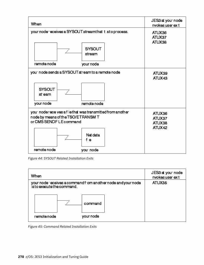
Figure 44: SYSOUT Related Installation Exits
Figure 45: Command Related Installation Exits
278 z/OS: JES3 Initialization and Tuning Guide

Monitoring Files Sent through TSO/E TRANSMIT or CMS SENDFILEA user at another node can send a file to a user at your node by using the TSO/E TRANSMIT or CMSSENDFILE command. (The TSO/E TRANSMIT command is part of the TSO/E interactive data transmissionfacility, described in z/OS TSO/E Command Reference. To receive the file, the user at your node (this user iscalled the receiver) must issue the TSO/E RECEIVE command.
When an incoming file arrives, JES3 does not notify the receiver. The receiver finds that there is a file onlyafter issuing the TSO/E RECEIVE command.
To notify the receiver that an incoming file has arrived or to monitor incoming files, write an exit routine forinstallation exit IATUX42. This exit routine can:
• Check the validity of a file's control information• Accept a file and notify the receiver that the file has arrived• Delete a file• Notify the sender of a file that the file has been deleted
To find out how to code IATUX42, see z/OS JES3 Customization.
The system may not allow you to transmit a data set that it determines to be too large. The systemcompares the values you specify for the output limit on the TSO/E OUTLIM parameter with the value youspecify on the CARDS= parameter of the JES3 STANDARDS statement. When SYSOUT is transmitted inthe foreground for started tasks and TSO/E logons, the system uses the lower of these two limits. JES3sets the following output limits for started tasks and TSO logons:
• 999,999 for lines, cards, and pages• 2,147,483 (in thousands of bytes) for spool utilization.
An installation can change the limits for started tasks or TSO logons by using JES3 Exit 20 to change thelimit for each particular started task or TSO logon. The limit for TSO/E transmits which are specifiedthrough the OUTLIM parameter, should not be greater than the limit JES3 sets for punches or a X'722'abend will occur. See z/OS TSO/E Customization for information about limiting the TSO/T transmitcommand.
Deleting Files from the SpoolFiles sent to a user by means of the TSO/E TRANSMIT or CMS SENDFILE command are written to thespool. They stay there until the user issues a RECEIVE command. At that time, JES3 frees the spool spaceoccupied by the files.
It is possible for one or more of these files to remain on the spool indefinitely. This will happen when filesare sent to a user who does not issue the RECEIVE command frequently--the user could be on vacation,for example. It will also happen if files are sent to a user whose user identification is not known to yoursystem. Depending on the size and number of these files they could tie up considerable spool space.
One way to prevent such files from tying up spool space is to write an exit routine for installation exitIATUX42. The exit routine can:
• Delete files that are sent to a TSO user id not known to your system• Delete files that are sent to a user who will not issue the RECEIVE command for some time
General NJE ConsiderationsSee the CIPARM statement in z/OS JES3 Initialization and Tuning Reference for information on the defaultvalues used during Converter/Intrepreter (C/I) processing for a job submitted to a node through NJE.
JES3 Networking 279

280 z/OS: JES3 Initialization and Tuning Guide

Chapter 12. JES3 support for IBM tape libraries
This section describes JES3 support for automated, manual, and virtual IBM tape libraries. This supportenables a JES3 installation to manage tape drives within an IBM tape library.
JES3 support overviewJES3 supports the definition and usage of one or more IBM tape libraries within a JES3 complex. The tapedrives within a given library are subdivided into library device groups (LDGs) based on the type of device(machine and model type). JES3 uses specific esoteric names to direct tape allocations to devices withinthe correct library when the tape resides in a library, and to drives outside of a library when the tape is notresident within a library.
The esoteric names for devices comprising a LDG are conveyed to JES3 through the SETNAMEinitialization statement. These esoteric names, in conjunction with the SETNAME statement, allow JES3to associate the devices to a device group, the device groups to a library, and the libraries to a JES3complex.
Allocation for tape library data setsDFSMS/MVS directs new data sets to IBM tape libraries using the data class, storage class, and storagegroup information specified in JCL or provided by Automatic Class Selection (ACS). Storage classidentifies the data set as DFSMS/MVS managed mountable. Data class is used to determine the requiredmedia and tape device. Storage group is used to determine the eligible tape libraries. Requests for olddata sets are directed to a tape library only when the volume or volumes containing the data set arelocated within the tape library. Eligible tape devices are determined from the media type and recordingformat.
JES3 initialization statementsYour initialization deck must include JES3 SETNAME, DEVICE and HWSNAME statements for the tapelibrary. These statements define the IBM tape library to JES3, ensuring that non-library requests are notallocated to tape library drives.
Neither JES3 nor DFSMS/MVS verifies that a complete and accurate set of initialization statements aredefined to the system. A tape library definition that is either incomplete or inaccurate may result in jobsfailing allocation or other unpredictable results.
Before defining the devices within a library to JES3, they must be properly defined to MVS using thehardware configuration definition (HCD) program. Unlike a JES2 environment, a JES3 operatingenvironment requires the specification of esoteric unit names for the devices within a library. These unitnames will be used in the required JES3 initialization statements.
Each device within a library must have four esoteric names associated with it. These are:
1. The complex-wide name, this is always: LDGW3495.2. The library-specific name, this is an 8-character string composed of the LDG prefix, followed by the 5-
digit library identification number.3. The complex-wide device name. Table 54 on page 282 specifies the name to be used for each type of
device (machine and model type).4. A library-specific device name, which consists of the 5-digit library device number prefixed by a 3-
character device type identifier. Table 54 on page 282 specifies the name to be used for each tapedevice.
In addition to the four esoteric names, there is a fifth esoteric name that must be defined if the allocationassist support available with the TS7700 Virtualization Engine is used. The library-specific distributed
© Copyright IBM Corp. 1988, 2017 281

name is an 8-character string composed of the LDX prefix followed by the 5-digit library identificationnumber. For a detailed discussion of the allocation assist support (for specific and scratch allocations) inthe TS7700 Virtualization Engine, enablement of this support in a JES3 environment, and example INISHdeck statements using the LDX esoteric names, refer to the z/OS DFSMS OAM Planning, Installation, andStorage Administration Guide for Tape Libraries.
Table 54: Device-specific library unitname table
Tape device Complex-wide devicename unitname
Library-specific devicename unitname
For additional library information
3490 LDG3490 LDDnnnnn Not applicable.
3490E LDG3490E LDEnnnnn Not applicable.
3590 Model B1x LDG3591 LDBnnnnn Not applicable.
3590 Model E1x LDG359E LDCnnnnn z/OS DFSMS Software Support for IBMTotalStorage Tape System 3590Models E1x/H1x, SC35-0484
3590 Model H1x LDG359H LDFnnnnn z/OS DFSMS Software Support for IBMTotalStorage Tape System 3590Models E1x/H1x, SC35-0484
3592 Model J1A LDG359J LDJnnnnn z/OS DFSMS Software Support for IBMSystem Storage TS1140, TS1130, andTS1120 Tape Drives (3592)
3592 Model E05 LDG359K LDKnnnnn z/OS DFSMS Software Support for IBMSystem Storage TS1140, TS1130, andTS1120 Tape Drives (3592)
3592 Model E05e(encryption capable)
LDG359L LDLnnnnn z/OS DFSMS Software Support for IBMSystem Storage TS1140, TS1130, andTS1120 Tape Drives (3592)
3592 Model E06 LDG359M LDMnnnnn z/OS DFSMS Software Support for IBMSystem Storage TS1140, TS1130, andTS1120 Tape Drives (3592)
3592 Model E07 LDG359N LDNnnnnn z/OS DFSMS Software Support for IBMSystem Storage TS1140, TS1130, andTS1120 Tape Drives (3592)
Note: All IBM tape devices since the 3590 Model B1x emulate the 3590 Model B and use 3590-1 as thedevice type (when defining the devices to HCD).
Before making changes to the JES3 initialization stream, define these esoteric names and obtain the inputfor the JES3 initialization stream checker.
You can also define additional esoteric names that users can specify by using the SMSHONOR JCLkeyword.
SETNAME statement
Include a SETNAME statement for each XTYPE. The NAMES list for the SETNAME statement must includeall required library device groups. It must not include any generic or esoteric names, such as 3590-1. Theomission of these esoteric and generic names is required to prevent tapes from being mounted onunsuitable devices; the one exception is user-defined names to be used with SMSHONOR. The namesspecified must be defined to MVS as esoteric names.
The grouping of library devices into XTYPE groups is the same process for all other JES3 manageddevices. The XTYPE groups are determined by the special esoteric names assigned during the HCDprocessing and associating the esoteric name to a device group. Use the following rules when composingyour SETNAME statements:
1. The complex-wide library name used on all statements is LDGW3495, regardless of the type of IBMtape library being used.
282 z/OS: JES3 Initialization and Tuning Guide

2. A library-specific name is included for all XTYPEs within a referenced library. The name has the prefixLDG followed by the 5-character library sequence number.
Note: The library sequence number is generally defined by the IBM service representative when thelibrary is installed and can be any 5-CHAR hexadecimal value.
3. A complex-wide device name is included for all XTYPEs associated with a specific type of device usedin the complex. The name has the prefix LDG followed by specific letters representing the type of tapedevice (for example, 359M for the 3592 Model E06).
4. A library-specific device name is included for all XTYPEs associated with the devices of the specifieddevice type within a given library. For 3490E drives, the name has a prefix of "LDE" followed by the 5-character library sequence number. For 3590 Model E06 devices, the name has a prefix of LDMfollowed by the 5-character library sequence number.
5. Optionally, a library-specific distributed name is included for all XTYPEs within a referenceddistributed library. The name has the prefix LDX followed by the 5-character library sequence numberof a TS7700 Virtualization Engine distributed library. If you are using the allocation assist supportavailable with the TS7700 Virtualization Engine, you must define the "LDX" name. For a detaileddiscussion of the allocation assist support for specific and for scratch allocations in the TS7700Virtualization Engine, enablement of this support in a JES3 environment, and example INISH deckstatements using the "LDX" special esoteric names, refer to z/OS DFSMS OAM Planning, Installation,and Storage Administration Guide for Tape Libraries.
6. Optionally, user-defined esoteric names are specified by using the SMSHONOR keyword.
The following guidelines will ensure correct generation of the SETNAME statements.
• The NAMES= list contains four special esoteric names that are used to identify library resident devices.Optionally, "LDX" names can also be defined for distributed libraries that are associated with a TS7700Virtualization Engine, and added as a fifth name. Additional names, which you can specify by using theSMSHONOR JCL keyword, might also be listed.
• There can never be esoteric names pertaining to different devices types in the same list (devices withdifferent machine and model types).
• There can never be two esoteric names for 3490, 3490E or 3590/3592 device identifiers in the samelist.
• There must be a corresponding library-specific device name if a complex-wide device name exists, andvice versa.
Following is an example of a SETNAME statement. It uses a library sequence number of 123DE:
SETNAME,XTYPE=LB13490E,NAMES=(LDGW3495,LDG123DE,LDG3490E,LDE123DE) . . . . . . . . . . . . Complex Library Complex Library Wide Specific Wide Specific Library Library Device Device Name Name Name Name
HWSNAME statement
Build the HWSNAME statements for your library device groups using the following rules:
1. The complex-wide library name includes all other LDGs as alternates.2. The library-specific name includes all LDGs for the corresponding library as alternates. The complex-
wide device type name is also included as an alternate when all tape devices of a specific type arehoused within a single library.
3. The complex-wide device name includes all library-specific device names. When all devices of aspecific type are contained within a single library, the complex-wide device name is the same as thelibrary-specific name. In this case, the library-specific name should also be specified as an alternate.
4. The library-specific device name includes the following alternate names:
JES3 support for IBM tape libraries 283

a. When all drives within the library are the same machine and model type, the library-specific devicename is the same as the library name. The library-specific name should be specified as analternate.
b. When these are the only drives of this type in the complex, the complex-wide device name is thesame as the library-specific device name. Therefore, the complex-wide device name is specified asan alternate.
The following guidelines will ensure correct generation of the HWSNAME statements.
• There is a one to one correlation to HWSNAME statements as to special esoteric names defined in HCD.• There can never be esoteric names in the TYPE= lists that are not one of the special esoteric names.
Similarly, your existing HWSNAME statements for tape devices must not have any of these specialesoteric names in their TYPE= lists.
Following is an example of a HWSNAME statement:
HWSNAME,TYPE=(LDGW3495,LDG123DE,LDG3490E,LDE123DE)
DEVICE Statement
Include a DEVICE statement for each tape library drive in the complex.The XTYPE name must be uniquefor each type of device within a library and cannot span libraries. You should not specify the library as aJUNIT, or use the DTYPE or JNAME parameters. The absence of the DTYPE, JNAME and JUNITparameters will prevent inadvertent and unsuccessful use of a library device by a JES3 dynamic supportprogram (DSP).
Following is an example of a DEVICE statement:
DEVICE,XTYPE=(LB13490E,CA), XXUNIT=(590,SYSTEM1,S3,OFF,590,SY2,S3,OFF,590,SY3,S3,OFF)
Note: You can also use NUMDEV or *ALL to define your devices.
Library configuration exampleThe configuration described in this section is a JES3duplex with two libraries attached to it. An illustrationof the configuration and associated JES3 initialization statements are provided as examples to guide youin the installation and initialization of the library on your own system.
Figure 46 on page 285 illustrates the two libraries defined for this configuration. Library 1 (sequencenumber 123DE) has only 3490E tape drives. Library 2 (sequence number 123DF) has both 3490 and3490E drives.
284 z/OS: JES3 Initialization and Tuning Guide
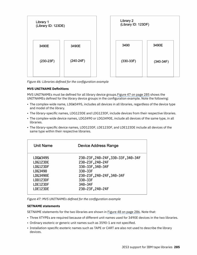
Figure 46: Libraries defined for the configuration example
MVS UNITNAME Definitions
MVS UNITNAMEs must be defined for all library device groups.Figure 47 on page 285 shows theUNITNAMEs defined for the library device groups in the configuration example. Note the following:
• The complex-wide name, LDGW3495, includes all devices in all libraries, regardless of the device typeand model of the library.
• The library-specific names, LDG123DE and LDG123DF, include devices from their respective libraries.• The complex-wide device names, LDG3490 or LDG3490E, include all devices of the same type, in all
libraries.• The library-specific device names, LDD123DF, LDE123DF, and LDE123DE include all devices of the
same type within their respective libraries.
Figure 47: MVS UNITNAMEs defined for the configuration example
SETNAME statements
SETNAME statements for the two libraries are shown in Figure 48 on page 286. Note that:
• Three XTYPEs are required because of different unit names used for 3490E devices in the two libraries.• Ordinary esoteric or generic unit names such as 3590-1 are not specified.• Installation-specific esoteric names such as TAPE or CART are also not used to describe the library
devices.
JES3 support for IBM tape libraries 285

SETNAME,XTYPE=(LB13490E,TA), NAMES=(LDGW3495,LDG123DE,LDG3490E,LDE123DE) . . SETNAME,XTYPE=(LB23490,TA), NAMES=(LDGW3495,LDG123DF,LDG3490,LDD123DF) . . SETNAME,XTYPE=(LB23490E,TA), NAMES=(LDGW3495,LDG123DF,LDG3490E,LDE123DF)
Figure 48: SETNAME statements for the configuration example
HWSNAME statements
HWSNAME statements for the two libraries are shown in Figure 49 on page 286. Note the alternate namesused in the HWSNAME statements.
HWSNAME,TYPE=(LDGW3495,LDG123DE,LDG123DF,LDE123DE,LDE123DF, LDD123DF,LDG3490,LDG3490E) . HWSNAME,TYPE=(LDG123DE,LDE123DE) . HWSNAME,TYPE=(LDG123DF,LDE123DF,LDD123DF,LDG3490)¹ . HWSNAME,TYPE=(LDE123DE,LDG123DE)² . HWSNAME,TYPE=(LDE123DF) . HWSNAME,TYPE=(LDD123DF,LDG3490)¹ . HWSNAME,TYPE=(LDG3490,LDD123DF) . HWSNAME,TYPE=(LDG3490E,LDE123DE,LDE123DF,LDG123DE)²
. . .
Notes:
1. LDG3490 is a valid alternate for LDG123DF and LDD123DF because there are no 3490 drives in the other library.
2. LDG123DE is a valid alternate for LDG3490E and LDE123DE because that library contains only 3490E drives.
Figure 49: HWSNAME Statements for the Configuration Example
DEVICE statements
DEVICE statements for the two libraries are shown in Figure 50 on page 287. Note that none of theDEVICE statements have DTYPE, JNAME or JUNIT values. This prevents the devices from being used byJES3 dynamic support programs, which do not work with library drives. These are strictly executiondevices.
286 z/OS: JES3 Initialization and Tuning Guide

DEVICE,XTYPE=(LB13490E,CA), XUNIT=(230,*ALL,S3,OFF),NUMDEV=32 * DEVICE,XTYPE=(LB23490,CA), XUNIT=(330,*ALL,S3,OFF),NUMDEV=16 * DEVICE,XTYPE=(LB23490E,CA), XUNIT=(340,*ALL,S3,OFF),NUMDEV=16
Figure 50: DEVICE Statements for the Configuration Example
Operational considerationsMost JES3 processing capabilities are fully supported with IBM tape libraries; however, certaincommands and functions are modified. Although no JCL changes are required, there are a few processingrestrictions and limitations associated with using the library in the JES3 environment. These operationalconsiderations are described in this section.
Unchanged functionsThe following JES3 functions and interfaces are fully supported without change for IBM tape libraries:
• Volume unavailable table• Dynamic device reconfiguration (DDR)• High water mark setup (HWS)• Unit affinity• Operator commands• Drive sharing
– If the SMS complex and JES3 complex are the same, the library can be shared among all systems in aJES3 complex.
• Device fencing
– Fencing capabilities include job group and dependent job control (DJC) net jobs.
Although you can fence library drives, you must ensure that the drives fenced are eligible to satisfythe volume request. For example, JES3 may fence two drives in a pool for a particular library. If thejob requires a volume from a different library, the job may not be able to use the two drives.
Modified functionsSome of the following JES3 functions and messages have been modified for tape library processing;others have a different meaning in the library environment:
• Pre-execution setup• Dynamic allocation• Verification• Fetch messages• Mount messages• Breakdown Messages• Online and Offline Status• Dump Job DSP
JES3 support for IBM tape libraries 287

Pre-execution setupDrive, volume, and data set allocation are performed for pre-execution setup; however, volume mountand verification is deferred until job execution. Setup continues to select a device from the librarydevice group that best meets the requirements of the data.
Dynamic allocationChanges to dynamic allocation are the same as those described for pre-execution setup.
VerificationWith library mount processing deferred until execution, JES3 verification is no longer performed. JES3verification is not needed because human error is no longer a factor and extensive verification isalready performed by OPEN processing.
Note: If all mounts within a job are deferred, the job will not be included in the setup depth (SDEPTH)parameter. This could impact your ability to control the JES3 workload.
Fetch messagesThe purpose of fetch messages is to alert operations of an impending need for specific tape cartridgesso that the tapes can be pulled from library shelves and mounted before the requests are processed.Because cartridges in a library are already located within arms' reach of a robotic accessor, fetchmessages to the operator are no longer necessary.
All fetch messages (IAT5110) for library requests are changed to the informational "USES" form of themessage. Unlike the "GET" form, no action is required for these messages. The fetch messages arerouted to the same console destination as other "USES" type fetch messages. This destination isspecified on the MDSLOG parameter of the SETPARAM initialization statement.
Mount MessagesMount messages are suppressed for IBM tape libraries.
Breakdown MessagesBreakdown messages issued for library volumes are irrelevant and could confuse operationspersonnel. Therefore, breakdown messages IAT5410 and IAT5420 for library requests are not issuedto the operator's console. They will continue to be written to the JES3 message log (JESMSGLG) dataset.
Online and Offline StatusDevices will automatically be varied offline to JES3 if the operator uses the VARYSMS,LIBRARY(libname),OFFLINE command. Devices will automatically be varied online to JES3 if theoperator uses the VARY SMS,LIBRARY(libname),ONLINE command. Refer to z/OS DFSMS OAMPlanning, Installation, and Storage Administration Guide for Tape Libraries for more informationconcerning the VARY SMS command.
Dump Job DSPThe dump job DSP runs in two modes: non-server mode and server mode. In non-server mode theinstallation uses the JUNIT and XUNIT initialization parameters of the DEVICE initialization statementto define the tape units the dump job will use. These tape units cannot be in an IBM tape library. Inserver mode the dump job process runs in its own address space (not in the JES3 address space) andcan use any tape device in the MVS/JES3 system including IBM tape libraries. In server mode, theJES3 installation can remove the JUNIT and XUNIT parameters from the DEVICE initializationstatement through a hot start with refresh. Furthermore, if the JES3 installation does not use JES3setup or does not use JES3 setup to manage tape devices, all tape DEVICE initialization statementsand associated SETNAME statements can be removed from the initialization stream; this still requiresa warm or cold start.
JES3 limitationsThe following functions have limited capability for IBM tape libraries in the JES3 environment:
• Support units• Device connectivity• Storage group states• Scratch integrated cartridge loader requests
288 z/OS: JES3 Initialization and Tuning Guide

• Mixed JES3-managed and non-managed devices• Library device groups specified in JCL
Support unitsTape library drives cannot be used as support units by JES3 dynamic support programs. Therefore,you should not specify DTYPE, JUNIT, and JNAME parameters in your initialization deck.
JES3 does not prevent tape library drives from being defined as support units. It also does not preventthem from being allocated to a dynamic support program. If this does occur, however, the dynamicsupport program must be canceled and restarted with a non-tape library drive.
Device connectivityAll control units within an IBM tape library must be connected to every system in a JES3 complex.Otherwise, all jobs using the libraries must complete converter/interpreter (CI) processing and locateprocessing on a system that has each of the libraries attached to it.
The device configuration within a library is obtained by DFSMS/MVS during IPL or whenever a drive isvaried online. This information is used during CI processing and locate processing to determineeligible JES3 devices.
If CI processing or locate processing are performed on a system that does not have connectivity to alltape drives within a tape library, those drives would be unknown and considered ineligible for JES3setup. This could result in an allocation failure.
Storage group statesStorage group states are not supported for tape libraries as compared to the support for DASD:
• Because they are not used to determine the eligible JES3 mains, storage group states do notinfluence JES3 system selection. Therefore, you cannot use them to steer jobs to eligible systems.Library drives must remain offline to ineligible systems to prevent JES3 from scheduling jobs tothem.
Note: If the SMS system selection SSI is called for DASD data sets, the tape storage groups stateswill not influence the setting of the JES3 main mask.
• Storage group states are not used to determine eligible devices for JES3 requests. Although JES3selects the library device, it must also be eligible for MVS allocation or the job will fail allocation.Because JES3 allocates library drives before job processing, and MVS allocation determines eligibledevices using the Storage Group state in effect when the job runs, changes between CI processingand job processing could invalidate the device selected by JES3.
To ensure that changes to storage group states do not affect job execution, you should define themas "enabled" to all tape library-eligible systems and not change their state while tape library-eligiblejobs are queued to run.
Mixed JES3-managed and non-managed devicesTape library drives within a complex should all be either JES3-managed or non-JES3-managed. MixingJES3-managed and non-managed devices could prevent the non-managed devices from being usedfor new data set allocations and reduces device eligibility for existing data sets. This results inallocation failures or delays in job setup.
Library device groups specified in JCLLDG names are permitted in JCL but should not be used.
DFSMS/MVS determines an appropriate library device group name for JES3 setup from the data classand storage group assigned to the data set. It replaces the unitname found in the JCL. Because this isdone after ACS processing, the JCL-specified unitname is still available to the ACS routines. Althoughan LDG name specified as a unitname in JCL cannot be used to direct allocations to a specific libraryor library device type, it can be used for ACS filtering or even to disallow the JCL-specified librarydevice group names.
JES3 support for IBM tape libraries 289

Mount failuresMount failures occur when the system is re-IPLed and tries to mount a tape on a drive other than the drivethe tape was last mounted on.
To locate the volumes for which a mount failure occurred:
1. As appropriate, go to the library's interface or console.2. Select the database search function.3. Locate all mounted volumes. The display will show the tape drive identifier for each mounted volume.4. Return to the MVS operator's console and issue DISPLAY U commands for each mounted tape drive. If
the volume is not actually being used, for example, by a job running in a complex that shares thelibrary, issue an MVS UNLOAD command for the device.
Refer to the library's operator guide or customer information center for more information about the database search function.
JES3With few exceptions, the use of the IBM 3590/3592 tape subsystem as an execution device in a JES3complex is transparent to JES3. You must define the devices to JES3 in the initialization stream for JES3to manage the devices. Once defined, JES3 manages the IBM 3590/3592 drives in the same way that itmanages other tape devices.
Note: All IBM tape devices since the 3590 Model B1x emulate the 3590 Model B1x and use the genericunit name 3590-1, including all 3590 and 3592 devices. Esoteric names are required to differentiate IBM3590/3592 tape subsystem models.
To update the JES3 Initialization stream follow the steps described below:
1. Specify the generic unit name and any esoteric unit names by which the IBM 3590 drives may berequested; use one or more SETNAME statements.
2. Specify these unit names on HWSNAME statements, if you are using High Watermark Setup, or catalogoverrides--for example, if a unit name specified on JCL is more restrictive than the IBM 3590/3592generic unit name of 3590-1. In these cases, the JCL unit name will override the unit name in thecatalog.
The rules for specifying the IBM 3590/3592 unit names on these statements are the same as for otherdevice types. For example, each unit name must appear as the primary unit name on one HWSNAMEstatement.
Note: Because IBM 3590/3592 is not compatible with other tape device types, the alternate unitnames that follow the primary name must not contain any other device type.
3. Define the IBM 3590/3592 drives using DEVICE statements. If the JUNIT parameter is specified, theDTYPE should be specified as TA435901.
To request an IBM 3590/3592 drive for the DUMP Job DSP, you may specify TA4 or TA435901 or thedevice address on the IN= or OUT= parameter. You can request compaction using the existing MOD=key word. Do not use the DEN= key word: it is ignored except for a warning message because the IBM3590/3592 writes a single density tape.
Other JES3 Tape Dynamic Support Programs (DSPs) such as Tape Label or Tape-to-tape do notsupport the IBM 3590/3592 devices.
4. If the IBM 3590/3592 tape subsystems are installed in an IBM tape library, you must define thefollowing esoteric names:
• LDBsssss, which includes all IBM 3590 devices in the library with library ID sssss.• LDG3591, which includes all IBM 3590 devices in any library.
290 z/OS: JES3 Initialization and Tuning Guide

• LDCsssss, which includes all IBM 3590 Model E1x devices in the library with library ID sssss.• LDG359C, which includes all IBM 3590 Model E1x devices in any library.• LDFsssss, which includes all IBM 3590 Model H1x devices in the library with library ID sssss.• LDG359F, which includes all IBM 3590 Model H1x devices in any library.• LDJsssss, which includes all IBM 3592 Model J1A devices in the library with library ID sssss.• LDG359J, which includes all IBM 3592 Model J1A devices in any library.• LDKsssss, which includes all IBM 3592 Model E05 devices in the library with library ID sssss.• LDG359K, which includes all IBM 3592 Model E05 devices in any library.• LDLsssss, which includes all IBM 3592 Model E05e (encryption capable) devices in the library with
library ID sssss.• LDG359L, which includes all IBM 3592 Model E05e (encryption capable) devices in any library.• LDMsssss, which includes all IBM 3592 Model E06 devices in the library with library ID sssss.• LDG359M, which includes all IBM 3592 Model E06 devices in any library.• LDNsssss, which includes all IBM 3592 Model E07 devices in the library with library ID sssss.• LDG359N, which includes all IBM 3592 Model E07 devices in any library.
Note: The name 3590-1 and any nonlibrary esoteric unit name must not include any library devices.
Figure 51 on page 291 shows the sample JES3 definitions for an IBM tape library with one string of four3590 Model B1x tape drives. The library name in this example is F4006.
SETNAME,XTYPE=LB135901,NAMES=(LDGW3495,LDGF4006,LDG3591,LDBF4006) | | | | V V V V Complex Library Complex Library Wide Specific Wide Specific Library Library Device Device Name Name Name Name
DEVICE,XTYPE=(LB135901,TA),XUNIT=(500,SY1,TAP,OFF) DEVICE,XTYPE=(LB135901,TA),XUNIT=(501,SY1,TAP,OFF) DEVICE,XTYPE=(LB135901,TA),XUNIT=(502,SY1,TAP,OFF) DEVICE,XTYPE=(LB135901,TA),XUNIT=(503,SY1,TAP,OFF) HWSNAME,TYPE=(LDGW3495,LDGF4006,LDG3591,LDBf4006) HWSNAME,TYPE=(LDGF4006,LDG3591,LDBF4006,LDGW3495) HWSNAME,TYPE=(LDG3591,LDBF4006,LDGW3495,LDGF4006) HWSNAME,TYPE=(LDBF4006,LDGW3495,LDGF4006,LDG3591)
Figure 51: Sample JES3 definitions for IBM 3590 Model B1x with an IBM tape library
You could also define the entire library with one DEVICE statement by defining it as follows:DEVICE,XTYPE=(LB135901,TA),XUNIT=(500,*ALL,TAP,OFF),NUMDEV=4
The complex-wide library name is always LDGW3495, regardless of the IBM tape library device type andmodel, and includes all IBM tape libraries.
Note: IBM 3590/3592 drives installed in an IBM tape library cannot be used to as support units for JES3DSPs. Therefore, do not specify DTYPE, JUNIT, and JNAME parameters on the DEVICE statement. Nocheck is made during initialization to prevent library drives from being defined as support units, and nocheck is made to prevent the drives from being allocated to a DSP if they are defined. Any attempt to call atape DSP by requesting an IBM tape library fails because the DSP is unable to allocate an IBM tape librarydrive.
Job Entry Subsystem 3 (JES3), an MVS subsystem, manages resources and workflow before and afterjobs are processed.
Tape verification processing (IATLVVR module)JES3 tape verification processing, which is done by the IATLVVR module, extracts VOLSER informationfrom the volume's sense data if a volume with a later recording format is mounted on a drive that cannot
JES3 support for IBM tape libraries 291

read or write in that recording format; for example, if a 256TRACK scratch tape is mounted on a128TRACK drive.
Migration considerationsAdd new esoteric names to JES3 initialization decks. For early JES3 releases, you need to check for allnew esoteric names in order to suppress such operator messages as IAT5110 (fetch) and IAT5410 (keep/retain).
IBM 3590/3592 support for JES3In a z/OS JES3 environment, the IBM 3590/3592 tape devices are supported by JES3. All IBM3590/3592 tape devices are defined as 3590 Model B1x devices and use the generic unit name 3590-1.
To use the devices in a JES-managed IBM tape library, refer to “JES3” on page 290 for the esoteric namesthat must be defined for the complex-wide device name, the library-specific device name in HCD, and theJES3 SETNAME initialization parameter.
DTYPE for JUNIT
When IBM 3590/3592 tape devices are used as JES3-managed devices, they must be defined on DEVICEstatements in the JES3 initialization parameter. If the JUNIT parameter is specified in the DEVICEstatement, the DTYPE must be specified as TA435901.
JES3 Dump Job Dynamic Support Program
The JES3 Dump Job (DJ) Dynamic Support Program (DSP) supports the IBM 3590/3592 tape device fordumping and restoring the JES3 spool. When the operator calls the Dump Job DSP, TA435901, TA4, or thedevice number can be specified on the IN= or OUT= parameter in the JES3 CALL,DJ command. Theoperator can also specify compaction.
292 z/OS: JES3 Initialization and Tuning Guide

Appendix A. Accessibility
Accessible publications for this product are offered through IBM Knowledge Center (www.ibm.com/support/knowledgecenter/SSLTBW/welcome).
If you experience difficulty with the accessibility of any z/OS information, send a detailed email messageto [email protected].
Accessibility features
Accessibility features help users who have physical disabilities such as restricted mobility or limited visionuse software products successfully. The accessibility features in z/OS can help users do the followingtasks:
• Run assistive technology such as screen readers and screen magnifier software.• Operate specific or equivalent features by using the keyboard.• Customize display attributes such as color, contrast, and font size.
Consult assistive technologiesAssistive technology products such as screen readers function with the user interfaces found in z/OS.Consult the product information for the specific assistive technology product that is used to access z/OSinterfaces.
Keyboard navigation of the user interfaceYou can access z/OS user interfaces with TSO/E or ISPF. The following information describes how to useTSO/E and ISPF, including the use of keyboard shortcuts and function keys (PF keys). Each guide includesthe default settings for the PF keys.
• z/OS TSO/E Primer• z/OS TSO/E User's Guide• z/OS ISPF User's Guide Vol I
Dotted decimal syntax diagramsSyntax diagrams are provided in dotted decimal format for users who access IBM Knowledge Center witha screen reader. In dotted decimal format, each syntax element is written on a separate line. If two ormore syntax elements are always present together (or always absent together), they can appear on thesame line because they are considered a single compound syntax element.
Each line starts with a dotted decimal number; for example, 3 or 3.1 or 3.1.1. To hear these numberscorrectly, make sure that the screen reader is set to read out punctuation. All the syntax elements thathave the same dotted decimal number (for example, all the syntax elements that have the number 3.1)are mutually exclusive alternatives. If you hear the lines 3.1 USERID and 3.1 SYSTEMID, your syntaxcan include either USERID or SYSTEMID, but not both.
The dotted decimal numbering level denotes the level of nesting. For example, if a syntax element withdotted decimal number 3 is followed by a series of syntax elements with dotted decimal number 3.1, allthe syntax elements numbered 3.1 are subordinate to the syntax element numbered 3.
© Copyright IBM Corp. 1988, 2017 293

Certain words and symbols are used next to the dotted decimal numbers to add information about thesyntax elements. Occasionally, these words and symbols might occur at the beginning of the elementitself. For ease of identification, if the word or symbol is a part of the syntax element, it is preceded by thebackslash (\) character. The * symbol is placed next to a dotted decimal number to indicate that thesyntax element repeats. For example, syntax element *FILE with dotted decimal number 3 is given theformat 3 \* FILE. Format 3* FILE indicates that syntax element FILE repeats. Format 3* \* FILEindicates that syntax element * FILE repeats.
Characters such as commas, which are used to separate a string of syntax elements, are shown in thesyntax just before the items they separate. These characters can appear on the same line as each item, oron a separate line with the same dotted decimal number as the relevant items. The line can also showanother symbol to provide information about the syntax elements. For example, the lines 5.1*, 5.1LASTRUN, and 5.1 DELETE mean that if you use more than one of the LASTRUN and DELETE syntaxelements, the elements must be separated by a comma. If no separator is given, assume that you use ablank to separate each syntax element.
If a syntax element is preceded by the % symbol, it indicates a reference that is defined elsewhere. Thestring that follows the % symbol is the name of a syntax fragment rather than a literal. For example, theline 2.1 %OP1 means that you must refer to separate syntax fragment OP1.
The following symbols are used next to the dotted decimal numbers.? indicates an optional syntax element
The question mark (?) symbol indicates an optional syntax element. A dotted decimal numberfollowed by the question mark symbol (?) indicates that all the syntax elements with a correspondingdotted decimal number, and any subordinate syntax elements, are optional. If there is only one syntaxelement with a dotted decimal number, the ? symbol is displayed on the same line as the syntaxelement, (for example 5? NOTIFY). If there is more than one syntax element with a dotted decimalnumber, the ? symbol is displayed on a line by itself, followed by the syntax elements that areoptional. For example, if you hear the lines 5 ?, 5 NOTIFY, and 5 UPDATE, you know that thesyntax elements NOTIFY and UPDATE are optional. That is, you can choose one or none of them.The ? symbol is equivalent to a bypass line in a railroad diagram.
! indicates a default syntax elementThe exclamation mark (!) symbol indicates a default syntax element. A dotted decimal numberfollowed by the ! symbol and a syntax element indicate that the syntax element is the default optionfor all syntax elements that share the same dotted decimal number. Only one of the syntax elementsthat share the dotted decimal number can specify the ! symbol. For example, if you hear the lines 2?FILE, 2.1! (KEEP), and 2.1 (DELETE), you know that (KEEP) is the default option for theFILE keyword. In the example, if you include the FILE keyword, but do not specify an option, thedefault option KEEP is applied. A default option also applies to the next higher dotted decimalnumber. In this example, if the FILE keyword is omitted, the default FILE(KEEP) is used. However, ifyou hear the lines 2? FILE, 2.1, 2.1.1! (KEEP), and 2.1.1 (DELETE), the default optionKEEP applies only to the next higher dotted decimal number, 2.1 (which does not have an associatedkeyword), and does not apply to 2? FILE. Nothing is used if the keyword FILE is omitted.
* indicates an optional syntax element that is repeatableThe asterisk or glyph (*) symbol indicates a syntax element that can be repeated zero or more times. Adotted decimal number followed by the * symbol indicates that this syntax element can be used zeroor more times; that is, it is optional and can be repeated. For example, if you hear the line 5.1* dataarea, you know that you can include one data area, more than one data area, or no data area. If youhear the lines 3* , 3 HOST, 3 STATE, you know that you can include HOST, STATE, bothtogether, or nothing.
Notes:
1. If a dotted decimal number has an asterisk (*) next to it and there is only one item with that dotteddecimal number, you can repeat that same item more than once.
2. If a dotted decimal number has an asterisk next to it and several items have that dotted decimalnumber, you can use more than one item from the list, but you cannot use the items more thanonce each. In the previous example, you can write HOST STATE, but you cannot write HOST HOST.
294 z/OS: JES3 Initialization and Tuning Guide

3. The * symbol is equivalent to a loopback line in a railroad syntax diagram.
+ indicates a syntax element that must be includedThe plus (+) symbol indicates a syntax element that must be included at least once. A dotted decimalnumber followed by the + symbol indicates that the syntax element must be included one or moretimes. That is, it must be included at least once and can be repeated. For example, if you hear the line6.1+ data area, you must include at least one data area. If you hear the lines 2+, 2 HOST, and2 STATE, you know that you must include HOST, STATE, or both. Similar to the * symbol, the +symbol can repeat a particular item if it is the only item with that dotted decimal number. The +symbol, like the * symbol, is equivalent to a loopback line in a railroad syntax diagram.
Accessibility 295

296 z/OS: JES3 Initialization and Tuning Guide

Notices
This information was developed for products and services that are offered in the USA or elsewhere.
IBM may not offer the products, services, or features discussed in this document in other countries.Consult your local IBM representative for information on the products and services currently available inyour area. Any reference to an IBM product, program, or service is not intended to state or imply that onlythat IBM product, program, or service may be used. Any functionally equivalent product, program, orservice that does not infringe any IBM intellectual property right may be used instead. However, it is theuser's responsibility to evaluate and verify the operation of any non-IBM product, program, or service.
IBM may have patents or pending patent applications covering subject matter described in this document.The furnishing of this document does not grant you any license to these patents. You can send licenseinquiries, in writing, to:
IBM Director of LicensingIBM CorporationNorth Castle Drive, MD-NC119Armonk, NY 10504-1785United States of America
For license inquiries regarding double-byte character set (DBCS) information, contact the IBM IntellectualProperty Department in your country or send inquiries, in writing, to:
Intellectual Property LicensingLegal and Intellectual Property LawIBM Japan Ltd.19-21, Nihonbashi-Hakozakicho, Chuo-kuTokyo 103-8510, Japan
The following paragraph does not apply to the United Kingdom or any other country where suchprovisions are inconsistent with local law: INTERNATIONAL BUSINESS MACHINES CORPORATIONPROVIDES THIS PUBLICATION "AS IS" WITHOUT WARRANTY OF ANY KIND, EITHER EXPRESS ORIMPLIED, INCLUDING, BUT NOT LIMITED TO, THE IMPLIED WARRANTIES OF NON-INFRINGEMENT,MERCHANTABILITY OR FITNESS FOR A PARTICULAR PURPOSE. Some states do not allow disclaimer ofexpress or implied warranties in certain transactions, therefore, this statement may not apply to you.
This information could include technical inaccuracies or typographical errors. Changes are periodicallymade to the information herein; these changes will be incorporated in new editions of the publication.IBM may make improvements and/or changes in the product(s) and/or the program(s) described in thispublication at any time without notice.
This information could include missing, incorrect, or broken hyperlinks. Hyperlinks are maintained in onlythe HTML plug-in output for the Knowledge Centers. Use of hyperlinks in other output formats of thisinformation is at your own risk.
Any references in this information to non-IBM websites are provided for convenience only and do not inany manner serve as an endorsement of those websites. The materials at those websites are not part ofthe materials for this IBM product and use of those websites is at your own risk.
IBM may use or distribute any of the information you supply in any way it believes appropriate withoutincurring any obligation to you.
Licensees of this program who wish to have information about it for the purpose of enabling: (i) theexchange of information between independently created programs and other programs (including thisone) and (ii) the mutual use of the information which has been exchanged, should contact:
IBM CorporationSite Counsel2455 South Road
© Copyright IBM Corp. 1988, 2017 297

Poughkeepsie, NY 12601-5400USA
Such information may be available, subject to appropriate terms and conditions, including in some cases,payment of a fee.
The licensed program described in this document and all licensed material available for it are provided byIBM under terms of the IBM Customer Agreement, IBM International Program License Agreement or anyequivalent agreement between us.
Any performance data contained herein was determined in a controlled environment. Therefore, theresults obtained in other operating environments may vary significantly. Some measurements may havebeen made on development-level systems and there is no guarantee that these measurements will be thesame on generally available systems. Furthermore, some measurements may have been estimatedthrough extrapolation. Actual results may vary. Users of this document should verify the applicable datafor their specific environment.
Information concerning non-IBM products was obtained from the suppliers of those products, theirpublished announcements or other publicly available sources. IBM has not tested those products andcannot confirm the accuracy of performance, compatibility or any other claims related to non-IBMproducts. Questions on the capabilities of non-IBM products should be addressed to the suppliers ofthose products.
All statements regarding IBM's future direction or intent are subject to change or withdrawal withoutnotice, and represent goals and objectives only.
This information contains examples of data and reports used in daily business operations. To illustratethem as completely as possible, the examples include the names of individuals, companies, brands, andproducts. All of these names are fictitious and any similarity to the names and addresses used by anactual business enterprise is entirely coincidental.
COPYRIGHT LICENSE:
This information contains sample application programs in source language, which illustrate programmingtechniques on various operating platforms. You may copy, modify, and distribute these sample programsin any form without payment to IBM, for the purposes of developing, using, marketing or distributingapplication programs conforming to the application programming interface for the operating platform forwhich the sample programs are written. These examples have not been thoroughly tested under allconditions. IBM, therefore, cannot guarantee or imply reliability, serviceability, or function of theseprograms. The sample programs are provided "AS IS", without warranty of any kind. IBM shall not beliable for any damages arising out of your use of the sample programs.
Terms and conditions for product documentationPermissions for the use of these publications are granted subject to the following terms and conditions.
Applicability
These terms and conditions are in addition to any terms of use for the IBM website.
Personal use
You may reproduce these publications for your personal, noncommercial use provided that all proprietarynotices are preserved. You may not distribute, display or make derivative work of these publications, orany portion thereof, without the express consent of IBM.
Commercial use
You may reproduce, distribute and display these publications solely within your enterprise provided thatall proprietary notices are preserved. You may not make derivative works of these publications, or
298 z/OS: JES3 Initialization and Tuning Guide

reproduce, distribute or display these publications or any portion thereof outside your enterprise, withoutthe express consent of IBM.
Rights
Except as expressly granted in this permission, no other permissions, licenses or rights are granted, eitherexpress or implied, to the publications or any information, data, software or other intellectual propertycontained therein.
IBM reserves the right to withdraw the permissions granted herein whenever, in its discretion, the use ofthe publications is detrimental to its interest or, as determined by IBM, the above instructions are notbeing properly followed.
You may not download, export or re-export this information except in full compliance with all applicablelaws and regulations, including all United States export laws and regulations.
IBM MAKES NO GUARANTEE ABOUT THE CONTENT OF THESE PUBLICATIONS. THE PUBLICATIONS AREPROVIDED "AS-IS" AND WITHOUT WARRANTY OF ANY KIND, EITHER EXPRESSED OR IMPLIED,INCLUDING BUT NOT LIMITED TO IMPLIED WARRANTIES OF MERCHANTABILITY, NON-INFRINGEMENT,AND FITNESS FOR A PARTICULAR PURPOSE.
IBM Online Privacy StatementIBM Software products, including software as a service solutions, ("Software Offerings") may use cookiesor other technologies to collect product usage information, to help improve the end user experience, totailor interactions with the end user, or for other purposes. In many cases no personally identifiableinformation is collected by the Software Offerings. Some of our Software Offerings can help enable you tocollect personally identifiable information. If this Software Offering uses cookies to collect personallyidentifiable information, specific information about this offering’s use of cookies is set forth below.
Depending upon the configurations deployed, this Software Offering may use session cookies that collecteach user’s name, email address, phone number, or other personally identifiable information for purposesof enhanced user usability and single sign-on configuration. These cookies can be disabled, but disablingthem will also eliminate the functionality they enable.
If the configurations deployed for this Software Offering provide you as customer the ability to collectpersonally identifiable information from end users via cookies and other technologies, you should seekyour own legal advice about any laws applicable to such data collection, including any requirements fornotice and consent.
For more information about the use of various technologies, including cookies, for these purposes, seeIBM’s Privacy Policy at ibm.com/privacy and IBM’s Online Privacy Statement at ibm.com/privacy/details inthe section entitled “Cookies, Web Beacons and Other Technologies,” and the “IBM Software Productsand Software-as-a-Service Privacy Statement” at ibm.com/software/info/product-privacy.
Policy for unsupported hardwareVarious z/OS elements, such as DFSMS, JES2, JES3, and MVS, contain code that supports specifichardware servers or devices. In some cases, this device-related element support remains in the producteven after the hardware devices pass their announced End of Service date. z/OS may continue to serviceelement code; however, it will not provide service related to unsupported hardware devices. Softwareproblems related to these devices will not be accepted for service, and current service activity will cease ifa problem is determined to be associated with out-of-support devices. In such cases, fixes will not beissued.
Notices 299

Minimum supported hardwareThe minimum supported hardware for z/OS releases identified in z/OS announcements can subsequentlychange when service for particular servers or devices is withdrawn. Likewise, the levels of other softwareproducts supported on a particular release of z/OS are subject to the service support lifecycle of thoseproducts. Therefore, z/OS and its product publications (for example, panels, samples, messages, andproduct documentation) can include references to hardware and software that is no longer supported.
• For information about software support lifecycle, see: IBM Lifecycle Support for z/OS (www.ibm.com/software/support/systemsz/lifecycle)
• For information about currently-supported IBM hardware, contact your IBM representative.
TrademarksIBM, the IBM logo, and ibm.com are trademarks or registered trademarks of International BusinessMachines Corp., registered in many jurisdictions worldwide. Other product and service names might betrademarks of IBM or other companies. A current list of IBM trademarks is available on the Web atCopyright and Trademark information (www.ibm.com/legal/copytrade.shtml).
300 z/OS: JES3 Initialization and Tuning Guide

Index
Special Characters???????? userID 58(HCD) hardware configuration definition 2*MODIFY,CONFIG command
add C/I FSS 24//*FORMAT JES3 control statement
changing 124OSE information and 124override sequence
with “default” statement 129–132with “direct” statement 126, 127
//*MAIN control statement 92//*MAIN JES3 control statement
DEADLINE parameter 111LREGION parameter 118main selection for job execution 89PROC parameter 87, 156procedure library 87scheduler element 87SETUP parameter 97, 98SYSTEM parameter 89, 114, 214to specify the track group allocation size 172TYPE parameter 114UPDATE parameter 87, 156
//*NET JES3 control statementABCMP parameter 113DEVPOOL parameter 112examining with a installation exit routine 112for a nonstandard DJC job 114NHOLD parameter 112, 113RELSCHCT parameter 113
//*PAUSE JES3 control statement 182//*PROCESS JES3 control statement
effect on scheduler element 87for a nonstandard DJC job 112, 114
&RACLNDE profilecreating 44, 60description 60used in WRITER profile 70
&RACLNDE variablesuggested for JESJOBS profiles 42suggested for JESSPOOL profiles 65suggested for NODES profiles 47
&SUSER valueon ADDMEM operand in NODES class
description 39example showing simple NJE user translation 56
++++++++ userID 59
Aaccess
data set 229access list 34accessibility
contact IBM 293
accessibility (continued)features 293
acquireconsole 181
add device panel 226adding a device
FSS-managed printer 25printer 25
adding a FSS managed printer 24address space JCL statement limit
changing 152displaying 153selecting 152
ADDRSORT parameteron the SETPARAM initialization statement 100, 232
ALLOCATE parameteron the SETPARAM initialization statement 95
allocationof a resource 95
allocation for tape library data setautomatic class selection (ACS) 281data class 281storage class 281storage group 281
alternate stream member 7assign a security label 30assign/unassign facility 215assignable device 215assistive technologies 293authority
using RACF 72authorization
command 81authorizing inbound work (JES) 46authorizing outbound work 60authorizing use of printers 71automatic restart management
JES3 considerations 122AUX (auxiliary address space)
staging areaallocate 244
USAM bufferallocate 244determine how many to allocate 244
Auxiliary Address Space (JES3)JES3AUX 20
auxiliary taskdescription 245
available-devices queue 135avoidance of cold start 17
BBADTRACK initialization statement
impact on checkpoint data set size 202BADTRACK table
impact on checkpoint data set size 202
301
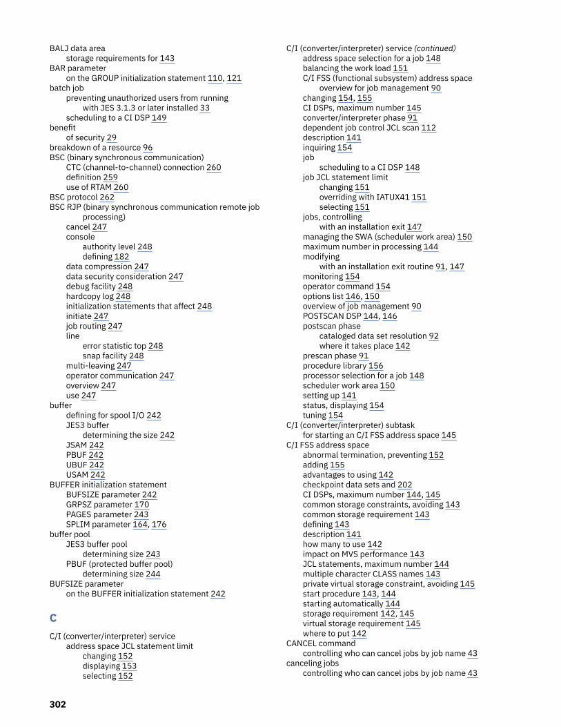
BALJ data areastorage requirements for 143
BAR parameteron the GROUP initialization statement 110, 121
batch jobpreventing unauthorized users from running
with JES 3.1.3 or later installed 33scheduling to a CI DSP 149
benefitof security 29
breakdown of a resource 96BSC (binary synchronous communication)
CTC (channel-to-channel) connection 260definition 259use of RTAM 260
BSC protocol 262BSC RJP (binary synchronous communication remote job
processing)cancel 247console
authority level 248defining 182
data compression 247data security consideration 247debug facility 248hardcopy log 248initialization statements that affect 248initiate 247job routing 247line
error statistic top 248snap facility 248
multi-leaving 247operator communication 247overview 247use 247
bufferdefining for spool I/O 242JES3 buffer
determining the size 242JSAM 242PBUF 242UBUF 242USAM 242
BUFFER initialization statementBUFSIZE parameter 242GRPSZ parameter 170PAGES parameter 243SPLIM parameter 164, 176
buffer poolJES3 buffer pool
determining size 243PBUF (protected buffer pool)
determining size 244BUFSIZE parameter
on the BUFFER initialization statement 242
CC/I (converter/interpreter) service
address space JCL statement limitchanging 152displaying 153selecting 152
C/I (converter/interpreter) service (continued)address space selection for a job 148balancing the work load 151C/I FSS (functional subsystem) address space
overview for job management 90changing 154, 155CI DSPs, maximum number 145converter/interpreter phase 91dependent job control JCL scan 112description 141inquiring 154job
scheduling to a CI DSP 148job JCL statement limit
changing 151overriding with IATUX41 151selecting 151
jobs, controllingwith an installation exit 147
managing the SWA (scheduler work area) 150maximum number in processing 144modifying
with an installation exit routine 91, 147monitoring 154operator command 154options list 146, 150overview of job management 90POSTSCAN DSP 144, 146postscan phase
cataloged data set resolution 92where it takes place 142
prescan phase 91procedure library 156processor selection for a job 148scheduler work area 150setting up 141status, displaying 154tuning 154
C/I (converter/interpreter) subtaskfor starting an C/I FSS address space 145
C/I FSS address spaceabnormal termination, preventing 152adding 155advantages to using 142checkpoint data sets and 202CI DSPs, maximum number 144, 145common storage constraints, avoiding 143common storage requirement 143defining 143description 141how many to use 142impact on MVS performance 143JCL statements, maximum number 144multiple character CLASS names 143private virtual storage constraint, avoiding 145start procedure 143, 144starting automatically 144storage requirement 142, 145virtual storage requirement 145where to put 142
CANCEL commandcontrolling who can cancel jobs by job name 43
canceling jobscontrolling who can cancel jobs by job name 43
302

catalog 214cataloged data set resolution 92cataloged start procedure
modifying for JES3 3sample 3
cataloged start procedure (JES3)statements 3
checkpoint data setadding 202allocate
risk 202space requirement 202where to place 202
allocating 202ensuring against loss 202I/O error
permanent 202minimizing effect of losing one 202replacing 202size, determining 202
checkpoint data setsreplacing or moving 203
CHKPNT2 data set 3CHOICE parameter
on the SELECT initialization statement 109, 110, 119CI DSP
effect on POSTSCAN DSP 144in C/I FSS address space
storage requirement 145inquiring 154number, maximum in an address space 144, 145status, displaying 154storage requirement 144
CIBATCH 148CICNT parameter
on the STANDARDS initialization statement 145CIDEMAND 148CIPARM initialization statement
PARMID parameter 150CKPNT data set 3class
security 30class 1 device 229class 2 device 229class 3 device 229CLASS initialization statement
and default job selection 117IORATE parameter 110, 114LSTRR parameter 118main selection 89MDEPTH parameter 110, 120MLIMIT parameter 110, 121SDEPTH parameter 98, 120SPART parameter 165SYSTEM parameter 89TDEPTH parameter 110, 120TLIMIT parameter 110, 120to define the job selection environment 114TRKGRPS parameter 172
CLAUTH (class authority) attributeexample for JESSPOOL class 66
CLIST execRACF sample 30
cold start
cold start (continued)Use of JCT Utility 17
command*MODIFY,CONFIG 24authorization 72, 81
command processingorder of execution 200
compatibility modedefinition 219specifying 219
conditional step execution consideration 93configuration
dynamically changing 24configuration example
configuration illustration 284console
acquiring 181authority checking 82authority level 82BSC RJP
defining 182defining 181description 181destination code
on the DEVICE initialization statement 98entering a command
JES3 command 183MVS command 183
JES3 181LOGON command 81management 182MCS 181MCS (multiple console support)
defining 181description 181
MCS LOGON 183multiple console support 182RJP (remote job processing)
description 181SNA RJP
defining 182console service
input processing 182operator communication 182overview 182
consolesLOGON 68
CONSTD initialization statementHARDCOPY parameter 185
contactz/OS 293
controlling where output can be processed 70controlling who can cancel jobs by job name 43controlling who can submit jobs by job class 42controlling who can submit jobs by job name 41converter/interpreter options list
defining 150selecting
by operator command 150for a started task 150for a TSO LOGON job 150for an internal reader job 150
converter/interpreter subtask 150copying
303

copying (continued)JCTs 210
creating 7CSA (common service area)
reduce the amount used by JES3 244CTC (channel-to-channel) connections 260CVOL (control volume) 214
DDAFETCH parameter
on the SETPARAM initialization statement 94data compaction 252data compression
with BSC RJP 247with SNA RJP 252
data management control block 143data set
access 229allocating 201bypassing JES3 checking 231cataloged
in a CVOL catalog 214in a VSAM catalog 214private 92resolution 92supplying data with a installation exit routine 92
checkpoint 202CHKPNT2 3, 6CKPNT 3, 6IATPLBnn 3, 6IATPLBST 3, 6, 11IATPLBT1 11integrity
differences between MVS and JES3 checking 231examples of effects on job processing 231
integrity checking 229JES3DRDS 3, 6JES3IN 3, 6, 11JES3JCT 3, 6JES3LIB 11JES3OUT 3, 6, 11JES3SNAP 3, 6JESABEND 3, 6, 11management 229multivolume
job setup processing 97MVS
integrity 230output
deleting 177deleting held 123held 123monitoring in a network 275providing with a TAT (track allocation table) 165spool partitions and 165
output processingnonstandard 123override sequence for information 124waiting for 123
overview 201partitioned use for INCLUDE 8resident
identifying 214
data set (continued)spool1 3, 6spoolnn 3, 6STEPLIB 3, 6, 11STG1CODE 11SYSABEND 3, 6SYSOUT
monitoring in a network 275providing TAT (track allocation table) 165spool partitions and 165
DD JCL statementmodifying with a installation exit routine 89OSE information and 124SYSOUT data set 124UNIT parameter 99, 100
DD statementJES3IN 9
DEADLINE DSPreinitializing after system stopped or quiesced 111
DEADLINE initialization statementand deadline scheduling algorithm 111
deadline schedulingdescription 111internal clock
resetting after system is stopped or quiesced 111debug facility
for BSC RJP 248default
process mode 216default NJE userID
ownership of SYSOUT based on NODES profiles 53specifying with SETROPTS command 58
default userIDsconcepts 58description 58
defineJES3 to RACF 37maximum number of jobs 203PSF/MVS printer 220SNA-attached printer 220
delete an output data setoutput data set 177
demand select jobdefinition 141scheduling to a CI DSP 149using system symbols in source JCL 149
DESTDEF statement 273determine
maximum number of printers 219device
allocationDD statement request 99dynamic 225system standard 100
assignable 215class
definition 229class specification 98DASD
record, track, and cylinder characteristics 171dedicating 99dedicating a specific device 100defining
prerequisite 214
304
device (continued)DJC networks, reserving for 112dynamic allocation
restriction 225esoteric group 226execution
definition 215fencing 227for a spool data set
choosing a track group size for 171I/O
allocating to JES3 225and MVS VARY command 214defining to JES3 215dynamically reconfiguring 227grouping 226layout 1management 228online/offline status 214reconfiguring 227
JES3defining 215definition 215
jointly-manageddefinition 215
multiple accessspecifying XUNIT parameter for 99
overview 214permanently resident 99pooling 227pooling for a job-class group 99, 227printer 217restricted 215selection
limiting effect on main eligibility 95setup and 96shared
definition 215subgeneric group
example 226volume 228volume removability 98
DEVICE initialization statementadding statements 215changing statements 215to define a network BSC line or CTC connection 269to define an I/O device
FSSNAME parameter 219MODE parameter 219PM parameter 219XTYPE parameter 228XUNIT parameter 98
to define processor statusDTYPE parameter 237
DEVICE statementexample of Device statement 284execution device 286JES3 dynamic support program 286
DEVICES classactivating 72
DEVPOOL parameteron the GROUP initialization statement 99, 227
DFC (data flow control) 249, 253DJ (dump job) 177
DJC (dependent job control)completion option 113description 112DJC network
cancel a network or job 113defining 112hold a network or job 113initializing 112job pending count 113modifying using an operator command 113purging 113release a network or job 113reserving devices for 112scheduling 112terminating 113
installation exit to examine //*NET statement 112JCL scan 112nonstandard DJC job processing 114to serialize catalog access 214
DLOG option 185DMC (data management control block)
storage requirements for 143DSI (dynamic system interchange)
writer output multitask facility and 245DSPCNT parameter
on the FSSDEF initialization statement 144, 145DTYPE parameter
on the DEVICE initialization statement 237dump job facility
using to free spool space 177DYNALLOC 6DYNALLOC initialization statement
and procedure library 156impact on checkpoint data set size 202to allocate a spool data set 160
dynamic allocationimproving performance 235reducing spool I/O requests 235
dynamic LPA facility 23dynamic writer 136
EEARLYVERIFY operand
SETROPTS command 37esoteric device type 226example
of a RACF profile 30EXEC JCL statement
interpretation 91modifying with a installation exit routine 89
execution devicedefining 216definition 215
exitthat affect security 36, 80
explicit setupadvantage 98description 98
EXRESC parameteron the GROUP initialization statement 99, 121, 227
external writeraccess to spool data sets 64
305
FFACILITY class
activating 70feedback xvFETCH parameter
on the SETPARAM initialization statement 94FMPS (function management presentation services) 251FORMAT initialization statement
impact on checkpoint data set size 202FSA (functional subsystem application)
installation exit 139FSS
adding a managed printer 24FSS (functional subsystem)
defining maximum number of printers 219FSS mode
definition 219specifying 219
FSSDEF initialization statementCI DSPs, defining the maximum number 144DSPCNT parameter 144, 145MAXASST parameter 144, 152PNAME parameter 144START parameter 144SYSTEM parameter 144to create a C/I FSS address space 144
FSSNAME parameteron the DEVICE initialization statement 219
Ggeneric profile
top profile in JESJOBS class 41global access checking table
entries for JESNEWS 67restored jobs
restored jobs 67global processor
restart characteristics 18GMS (generalized main scheduling)
controlling job scheduling 118deadline scheduling
description 111default job selection 117determine job eligibility 114
group IDstranslating 55
GROUP initialization statementand default job selection 117BAR parameter 110, 121DEVPOOL parameter 99, 227EXRESC parameter 99, 117, 121, 227JSPAN parameter 109, 110to define the job selection environment 114
GROUPJ qualifieron NODES profiles 47
GROUPS qualifieron NODES profiles 48
GRPSZ parameteron the BUFFER initialization statement 170on the SPART initialization statement 170
HHARDCOPY parameter
on the CONSTD initialization statement 185hardware configuration definition
using 10hardware configuration definition (HCD)
adding devices 223changing devices 223deleting devices 223
Hardware configuration definition (HCD) 2hardware configuration program
grouping a JES3 device 226HOME node
NETHOLD parameter 271hot start 13hot start with analysis 13hot start with refresh
starting JES3 5hot start with refresh and analysis 15hot writer 136how JES and RACF work together 32HWS (high-watermark setup)
advantage 97description 97
HWSNAME statementalternate name 286configuration example 286example of HWSNAME statement 283rules for building statement 283
II/O device 214I/O rate 109, 110, 114IATPLBnn data set 3IATPLBST data set 3, 11IATPLBT1 data set 11IATUTJCT
copying JCTs 210JCT Utility 210migrating 214running the utility 211setup and initialization 211testing the processing 213using the utility 212
IATUX03 installation exit 147IATUX04 installation exit 91, 147IATUX05 installation exit 91, 147IATUX06 installation exit 91, 147IATUX07 installation exit 92, 147IATUX08 installation exit 92, 147IATUX09 installation exit 147IATUX10 installation exit 147IATUX11 installation exit 92, 147IATUX15
*MODIFY,CONFIG processing 27IATUX17 installation exit 87IATUX18 installation exit 36, 76, 80, 82IATUX19 installation exit 80, 133, 139IATUX20 installation exit 139IATUX21 installation exit 139IATUX22 installation exit 139IATUX23 installation exit 139
306

IATUX24 installation exit 112IATUX25 installation exit 95IATUX26 installation exit 90, 147IATUX28 installation exit 89, 147IATUX29 installation exit 147, 167IATUX30 installation exit 36, 84IATUX31 installation exit 196IATUX33 installation exit 89, 147, 167IATUX34 installation exit 89, 124IATUX35 installation exit 36, 76, 80, 276IATUX36 installation exit 276IATUX37 installation exit 276IATUX38 installation exit 276IATUX39 installation exit 139, 276IATUX40 installation exit 276IATUX41 installation exit 91, 147, 151IATUX42 installation exit 276, 279IATUX43 installation exit 139, 276IATUX44 installation exit 89, 124IATUX45 installation exit 139IATUX46 installation exit 91, 147, 148IATUX48 installation exit 177IATUX49 installation exit 91, 147, 148IATUX58 installation exit 36, 76IATUX59 installation exit 36, 76IATUX60 installation exit 36IATUX61 installation exit 96IATUX62 installation exit 95IATUX67 installation exit 36id 156IEBUPDTE utility 3IEFPROC EXEC 3IKJEFF53 installation exit
and JESJOBS class 41, 43inbound SYSOUT definition
DESTDEF statement 273inbound work
authorizing 46INCL parameter
on the SELECT initialization statement 99, 120INCLUDE 6INCR parameter
on the SELECT initialization statement 99, 120INIT parameter
on the SPART initialization statement 165initialization data for JES3
isolating 163spool partition for, specifying 165
initialization of JES3 3initialization parameters
CIBATCH 148CIDEMAND 148
initialization statementused for security 77
initialization statementsINCLUDE 8protecting JES resources 29RJPWS 28RJPWS use 8
initialization streamchecker 10checker, data sets 11checker, sample JCL 11testing 10
initialization stream (continued)using segmented 8
initialization stream (JES3)statements
manage 7initialization stream checker
abnormal termination 12storage requirements 12
initiatoradding 117starting 117stopping 117
input data for a jobspool partition for 163
input servicecontrol statement processing phase
job flow overview 88internal reader 87main selection for job execution 89overview 87procedure library 87reader phase 87
input sourcesdefining nodes as local sources 60
installationGENERATE command 2hardware configuration definition 2plan for JES3 1RECEIVE/APPLY/ACCEPT 2
installation exitIKJEFF53 41
installation exit routineIATUX03 147IATUX04 91, 147IATUX05 91, 147IATUX06 91, 147IATUX07 92, 147IATUX08 92, 147IATUX09 147IATUX10 147IATUX11 92, 147IATUX17 87IATUX18 36, 76, 80, 82IATUX19 80, 133, 139IATUX20 139IATUX21 139IATUX22 139IATUX23 139IATUX24 112IATUX25 95IATUX26 90, 147IATUX28 89, 147IATUX29 167IATUX30 36, 84IATUX31 196IATUX33 89, 147, 167IATUX34 89, 124, 147IATUX35 36, 76, 80, 276IATUX36 276IATUX37 276IATUX38 276IATUX39 139, 276IATUX40 276IATUX41 91, 147, 151
307

installation exit routine (continued)IATUX42 276, 279IATUX43 139, 276IATUX44 89, 124, 147IATUX45 139IATUX46 91, 147, 148IATUX48 177IATUX49 91, 147, 148IATUX58 36, 76IATUX59 36, 76IATUX61 96IATUX62 95that affect security 35, 80
installation security plan 29integrity checking
data set 229internal reader
converter/interpreter options list for 150displaying the status of a job 138jobs read during input service 87output service and 138procedure library, default 88starting 138stopping 138
INTPMID parameteron the STANDARDS initialization statement 150
INTPROC parameteron the STANDARDS initialization statement 88
IORATE parameteron the CLASS initialization statement 110, 114
IRRDSC00 utilityfor JESSPOOL profiles 65
JJCL statement
address space JCL statement limitchanging 152displaying 153selecting 152
default specifications for the installation 150effect on SWA (scheduler work area) 150installation default 150job JCL statement limit
changing 151overriding with IATUX41 151selecting 151
maximum number processedin a C/I FSS address space 144, 152in the JES3 global address space 152
modify 89modifying 147parameter default 150scan for dependent job control 112
JCT (job control table)calculating the size 203
JCT Utility 210JDS (job data set)
output service 124JES (job entry subsystem)
how JES and RACF work together 32RACF support for 29security 29started procedures table 33
JES-managedjob class group 109job selection algorithm 109
JES3command processing 200
JES3 access to resourcedefining 37
JES3 auxiliary address space 244JES3 auxiliary task
description 245JES3 buffer
change the size 243determine the size 242
JES3 buffer pooldetermine the size 243
JES3 checkpointreplacing or moving 203
JES3 control statementmodify 89
JES3 deviceassignable 215defining 215definition 215eligible device type 215number 215reserving 215
JES3 disk reader facility 6JES3 global address space
abnormal termination, preventingwhen not enough SWA space 152
definition 141POSTSCAN DSP 146private virtual storage constraint, relieving 142, 145
JES3 initialization statementesoteric names 281tape library definition 281use of hardware configuration definition (HCD) program281
JES3 installationGENERATE command 2RECEIVE/APPLY/ACCEPT 2
JES3 maintenancegeneral 20overview 20philosophy 20restart information 21
JES3 monitoring facility (JMF) 19JES3 networking 259JES3 support
IBM Tape Library 281JES3 support overview
definition and usage 281esoteric names 281
JES3 system log 183JES3DRDS data set 3JES3IN data set 3, 11JES3JCT data set 3JES3LIB data set 11JES3OUT data set 3, 11JES3SNAP data set 3JESABEND data set 3, 11JESINPUT class
activating 46JESJOBS class
308

JESJOBS class (continued)activating 42, 44
JESNEWS data setprotecting 67
JESSPOOL classactivating 64
JESSPOOL profilesallowing users to create 66
jobaccessing output through TSO 138address space selection for C/I service 148aging 119assigning to spool partition 166authorizing NJE 51batch
scheduling to a CI DSP 149C/I service status, displaying 154catalog access, ensuring 214controlling through C/I service 146critical
ensuring spool space for 163defining maximum number 203demand select
definition 141JCL statement limit 152scheduling to a CI DSP 149use of SWA space 145using system symbols in source JCL 149
device dedication 99device pooling for a job-class group 99device selection
limiting effect on main eligibility 95DJC (dependent job control)
nonstandard 112, 114DJC completion option 113dummy partition, requesting 166execution queueing process 120group
selection span 109I/O rate mix 109, 114JCL statement
parameter defaults set by installation 150JCL statement limit
changing 151selecting 151
main eligibility 114main selection for execution 89management of a job 87maximum number in processing 144modifying DD statement information with a installationexit routine 91modifying job information with a installation exit routine91modifying step information with a installation exitroutine 91monitoring in a network 275primary spool space allocation 172priority barrier 110procedure libraries and
moving 157updating 156
processor dependencies, avoiding 214processor selection
for C/I service 148
job (continued)purging 140RAS, improving 162rescheduled 146resources, allocating for 92scheduling
controlling 118scheduling a processor for C/I service 91scheduling to a CI DSP 148secondary spool space allocation 172selecting an address space for C/I service 91selection
algorithm 109controlling 114defining the environment 114
setup typedescription 96explicit setup 98high-watermark setup 97job setup 97
spool partition selection 164spool space allocation 172spool space, effect on amount needed 159status in C/I service, displaying 154submitting to internal reader 138track group allocation size, specifying 172transmitting using JES3 networking 270
job classcatalog access, using to ensure 214defining 120device pooling for a job-class group 99execution resources, assigning 121grouping 121mains, eligible 89priority barrier for group 121
job class groupJES-managed 109
job classescontrolling the use of 41
job control table 203job data sets
protecting 64job entry network 259JOB JCL statement
modifying with a installation exit routine 89job JCL statement limit
changing 151overriding with IATUX41 151selecting 151
job managementC/I (converter/interpreter) service 90deadline scheduling
description 111GMS (generalized main scheduling)
controlling job scheduling 118default job selection 117determine job eligibility 114
input service 87JCL statement
modify 89JES3 control statement 89job class
defining 120grouping 121
309

job management (continued)job selection and scheduling
algorithm for selection 109controlling scheduling 118controlling selection 114defining the selection environment 114DJC (dependent job control) 112main eligibility 114
main selectionfor job execution 89
MDS (main device scheduler) 92output service 123overview 87procedure library
default 88purge
type 26 SMF record 140resource allocation
initializing MDS 98MDS (main device scheduler) 92overview 92setup type 96
scheduler elementmodifying the sequence 87standard sequence 87with //*MAIN JES3 control statement 87with //*PROCESS JES3 control statement 87
job mix 109, 114job names
controlling the use of 41job priority barrier 110job queue 109job scheduling
controlling 118job selection
and scheduling 100controlling
main eligibility 114defining the environment 114
job selection algorithmJES-managed 109WLM-managed 110
job setup//*MAIN JES3 control statement 97advantages and disadvantages 97description 97
JOB statementverifying that userID data is present on 37
job stepdefault region size 150maximum execution time 150
JOBMIX parameteron the SELECT initialization statement 109
jointly-managed devicedefinition 215
JSAM (JES3 spool access method)buffer pool size
BALJ data area 143data buffer block 143determine 243
JSPAN parameteron the GROUP initialization statement 109, 110
Kkeyboard
navigation 293PF keys 293shortcut keys 293
Llabel
for security 35limitations JES3
device connectivity 288function limitation 288library device groups 288mixed JES3 non-managed devices 288mixed JES3-managed devices 288scratch integrated cartridge loader request 288storage group state 288support unit 288
local nodestreating some network nodes as local nodes 60
local start local processor start 18LOCATE request
for a cataloged data set 92inhibiting JESMSG printing with a installation exitroutine 92
logical senderhow JES3 names them 271
logical storage 118LOGON command
for an MCS console 183long profile names
in JESSPOOL class 65LPA
dynamic LPA facility 23SETPROG command 23
LSTOR parameteron the SELECT initialization statement 118
LSTRR parameteron the CLASS initialization statement 118
LU (logical unit) 249
MMAGEL parameter
on the SELECT initialization statement 119MAGER parameter
on the SELECT initialization statement 119main
define 237limited by device selection 95selection for job execution
//*MAIN JES3 control statement 89CLASS initialization statement 89
MAINPROC initialization statementand default job selection 117PRTPAGE parameter 136, 244SELECT parameter 114, 119SPART parameter 165to define processor as main 237TRKGRPS parameter 172USRPAGE parameter 244
310

maintaining JES3general 20overview 20philosophy 20restart information 21
maintenance 20MAXASST parameter
on the FSSDEF initialization statement 144, 152on the STANDARDS initialization statement 152
maximum number of jobs 203MAXJOBST parameter
on the STANDARDS initialization statement 151MAXLINE parameter
on the NJERMT initialization statement 271MCS (multiple console support)
alternate console 182authority level 183backup console service 182console
defining 181guidelines for defining 181
log facility 183MPF (message processing facility) 183operator action message 183
MCS console 181MDEPTH parameter
on the CLASS initialization statement 110, 120MDS (main device scheduler)
allocation 95breakdown 96compared with MVS system allocation 93conditional step execution consideration 93description of processing 93device allocation
SETNAME initialization statement 99initialization 98listening for WLM changes 93operator control 100overview 92preparation 92SDEPTH parameter effect 120system select 94volume fetch 94volume verification 95WLM interaction 93
messageaction 183example of message suppression 197nonaction
suppressing display 196RETAIN and KEEP 96specifying for display suppression 197suppressing
example 197message class
for JES3 networking 275installation default 150
message processing facility 196migrating
using JCT Utility 214migration
defining JES as a started procedure with the trustedattribute 33restructured RACF database and JESSPOOL profiles 65
MLIMIT parameteron the CLASS initialization statement 110, 121
MODE parameteron the DEVICE initialization statement 219
modified functionsdynamic allocation 287modify JES3 function 287modify JES3 message 287pre-execution setup 287
modifying 7MPF (message processing facility) 196MVS
resource monitoring facility (RMF) 19system monitoring facility (SMF) 19
MVS assign/unassign facility 215MVS configuration program
JES3 devicenumber 215
MVS converter/interpreteroptions list for 150
MVS data setintegrity 230
MVS internal reader 137MVS system allocation
compared with MDS 93description of processing 93
MVS UNITNAMEdefinition for library device group 285
MVS workload managerWLM 92
MVS/BDT 261
NNAME parameter
on the SELECT initialization statement 119NAMES parameter
on the SETNAME initialization statement 99, 100NAU (network addressable unit) 249navigation
keyboard 293NCP (network control program)
SNA (system network architecture) 260NETDATA output 270, 271, 273NETHOLD parameter
HOME node 271network security
NJE network 46networking
BSC communication linedefining 269
BSC protocol 259buffer size
defining 267example of defining 268
changing node definitionchanging BDT initialization stream 273changing JES3 initialization stream 273, 274changing TCP/IP initialization stream 274continued data transfer 273synchronizing 273
communications pathdefining 265example 265
311

networking (continued)defining networking protocol 260directing SNA transaction 261general NJE considerations 279home node
defining 263installation exit routines for 275job
deciding how to transmit 270interleaving transmission 270
logical senderhow JES3 names them 271
message classdefining 275
monitor with an installation exit routine 275monitoring files sent using TSO/E TRANSMIT or CMSSENDFILE 279MVS/BDT work queue
hold-for queue 123networking request 123
nodeBSC (binary synchronous communication) 262defining 262definition 261, 262SNA (systems network architecture) 262TCP/IP 262
passwordspecifying 268
protocol 260remote node
adjacent 262defining 264directly-connected 262indirectly-connected 262nonadjacent 262
required initialization statement 261rerouting
job 275SYSOUT data set 275
SNA protocol 259spool file
deleting 279TCP/IP protocol 259
networking jobsubmitting networking jobs to JES3 138
networking profilesdescription 47understanding 47
networking protocolBSC (binary synchronous communication) 259SNA (systems network architecture) 259TCP/IP 259
NJEauthorizing jobs 51authorizing SYSOUT 53validating SYSOUT 55
NJE (network job entry)defining a network 259
NJE headerand security tokens 39
NJE jobswhere verified 38
NJE readeroutput service 138
NJE security 46NJE SYSOUT 53NJERMT initialization statement
MAXLINE parameter 271NETHOLD parameter 269parameter requirements for node type 262specifying a password 268STREAM parameter 271to define a networking communication line 269
NJEUSERID suboperandSETROPTS command 58
nodestreating some network nodes as local nodes 60
NODES classactivating 60SETROPTS RACLIST processing 60
NODES profilesdescription 47understanding 47
number of jobs 203
Ooperational considerations
processing restrictions and limitations 287operator
command authorization 81operator command
accepted from BSC RJP work station 248entering 182for C/I service 154for tuning a spool data set 177input processing 182monitoring in a network 275to balance the spool workload 176to communicate with a JES3 function 182to display spool status 176to modify a spool partition 177TSO/E command 84
operatorsassigning to RACF groups 33defining to RACF 33
OPTIONS initialization statementJOBNO parameter 203SE parameter 203
organizing 8Organizing the initialization stream 8OSE (output scheduling element)
content's source 124modifying information with a installation exit routine133output service 124override content's sequence 124scheduling to a writer 135
OSS (output scheduling summary entry) 134outbound work
authorizing 60using security labels 61
outputcontrolling where output can be processed 70providing with a TAT (track allocation table) 165spool partition, specifying 165spool partitions and 165
OUTPUT command (TSO/E)
312

OUTPUT command (TSO/E) (continued)operands allowed by JESSPOOL profiles 66
output data setdeleting 177
OUTPUT JCL statementeffect on output service 124OSE information and 124override sequence
with “direct” statement 125output service
accessing output through TSO 138installation exit 139internal reader 138output parameters 135output writer
available-devices queue 135waiting for work queue 135
overrides 135overview 123queueing output
hold-for queue 123output service hold queue 123output service writer queue 123
scheduling outputdetermining which output parameters apply 135
writing output 136output writer
as a functional subsystem 136available-devices queue 135dynamic writer 136external writer 137FSS (functional subsystem application) 136getting more work done 245hot writer 136MVS internal reader 137print writer 137punch writer 137starting 136stopping 136support routine 136timeout value 136waiting for work queue 135
output writer FSScanceling 218changing the definition 218defining 218defining maximum number of printers 219FSA (functional subsystem application)
installation exit 139letting JES3 define 218performance consideration 136restarting 218running a printer under 217running as dynamic writer 136spool data storage 136spool-access routine 136start procedure 218starting 218support routine 136
OUTSERV initialization statementOSE information and 124WC parameter 135WS parameter 135
OVRFL parameter
OVRFL parameter (continued)on the SPART initialization statement 164
PPAGES parameter
on the BUFFER initialization statement 243PARMID parameter
on the CIPARM initialization statement 150partition 162partitioned data set
editing 25use on INCLUDE 8use with initialization stream checker 11
passwordfor JES3 networking 268NJE job 60
PASSWORD parameteron JOB statement in JCL
consideration for inbound NJE jobs 49PEP (partitioned emulation programming) extension
SNA (system network architecture) 260performance
C/I FSS address space impact on MVS 143effect on POSTSCAN DSP 146improve
output writing capability 245improving
by identifying a resident data set 214by using a spool partition 162by using spool partition 163dynamic allocation 235spool 165
output writer FSS considerations 136overview 19spool data sets and 160
performance factors 19performance integrity
PROCLIB 7performance JES3
improvefix PBUF page 244
planningJES system programmer 29
planning for JES3classifying jobs 1configuration 1I/O device layout 1overview 1
PM parameteron the DEVICE initialization statement 219
PNAME parameteron the FSSDEF initialization statement 144
POOLNAMS parameteron the SETNAME initialization statement 100
POSTSCAN DSPeffect on performance 146for jobs processed in a C/I FSS address space 91inquiring 154limiting effect on job processing 144number, specifying the maximum 144, 146status, displaying 154
print writer 137printer
313
printer (continued)3800 model 3 219maximum for an output writer FSS 219output writer FSS, running under 217processing mode 220PSF/MVS 220SNA-attached 220
printer security 71priority barrier 110procedure library
assignment for a job 87default
internal reader 88started task 88TSO/E LOGON job 88
definition 156ensuring access by C/I service 142how to manage 156IBM-supplied 156input service 87job assignment 87managing 156members, specifying 156moving to another volume 157preventing an update 157standard procedure library 156status, displaying 157updating
preventing 157process mode
ALTPM keyword 216default 216defining 216
processing ordercommands 200
processorcompetition for spool data, limiting 162logical storage, defining 118message suppression, controlling
from a local processor 197sharing a system catalog 214spool data, limiting competition for 162uninitialized
identifying 228procid (procedure library id) 156PROCLIB
performance integrity 7profile
RACF sample 30propagation
across a network 40across nodes in an NJE network 59definition 40
PROPCNTL classactivating 38
protected data buffer 136protection
command 72console access 81NJE job password 60
protocolconverting networking protocol 260definition 259
PRTPAGE parameter
PRTPAGE parameter (continued)on the MAINPROC initialization statement 136, 244
PS (presentation service)data compaction 252data compression 252string control bite 252
pseudocommand 182PSTCNT parameter
on the FSSDEF initialization statement 146PU (physical unit) 249punch writer 137
RRAB (record allocation block)
storage requirements for 143RACF (Resource Access Control Facility)
command authority 72define JES3 access to a resource 37how security works 30sample profile 30security class 30security label 30, 35universal access authority 34
RACF databaserestructuring for JESSPOOL profiles 65
RACFVARS class&RACLNDE profile 60activating 60local nodes 60SETROPTS RACLIST processing 60
RAS (reliability, availability, and serviceability)improving for spool data 162
record allocation block 143recovery
improving through spool partition 163reliability, availability, and serviceability 162remote job processing
overview 247SNA RJP 249
remote workstation joband input service 87
remote workstationsprotecting 68
RESDSN initialization statement 214resident job queue 124resident volume allocation table 94resource
consolemanagement 182
data setmanagement 229
define JES3 access 37defining
effect on resource management 228dynamic allocation 234manage 237managing 201processor 237system log 183volume
management 232writer output multitask facility 245
resource allocation
314
resource allocation (continued)MDS (main device scheduler)
initialization 98overview 92setup type 96
resource breakdown 96resource management
effect of resource definition 228resource monitoring facility (RMF) 19RESQUEUE (resident job queue)
output service and 124restart
effect on networking job 273, 274job
effect of restart 273, 274networking job
effect of restart 273, 274restart
effect 273, 274warmstart 273
restart characteristicsglobal processor 18
restart information 21restricted device 215restructuring the RACF database
to allow long profile names 65reverse MAC (mandatory access checking)
for outbound work 61RJE consoles
protecting 68RJP consoles
protecting 68RSCS node
control of inbound jobs or data 46RU (request unit)
chain 253conversion 253
runningJCT Utility 211
RUSER qualifieron NODES profiles 47
SSAF (system authorization facility) 30SAGEL parameter
on the SELECT initialization statement 99, 120SAGER parameter
on the SELECT initialization statement 99, 119SAPI
access to spool data sets 65SBAR parameter
on the SELECT initialization statement 99, 119SCB (string control bite) 252scheduler control block
creation 91modifying before written to SWA 90SWA (scheduler work area) 150
scheduler elementmodifying the sequence 87standard sequence 87with //*MAIN JES3 control statement 87with //*PROCESS JES3 control statement 87
Scheduling Environments 93
SDEPTH parameteron the CLASS initialization statement 98, 120on the SELECT initialization statement 99, 120
SDSF (System Display and Search Facility)effect of JESSPOOL profiles on 66effect of WRITER profiles on 71
SECLJ qualifieron NODES profiles 48
SECLS qualifieron NODES profiles 48
securitybenefit 29class 30command 81considerations with BSC RJP 247installation exit 35JES3 installation exit 36, 80label 30, 35protection
command 72NJE job password 60RJP console 81
RACF interface 30SAF (system authorization facility) 30sample RACF profile 30universal access authority 34using an initialization statement 77
security definitionsmade for a TCP/IP/NJE Netserv 62
security labelsusing to control outbound work 61
segmented initialization streamusing 8
SELECT initialization statementCHOICE parameter 109, 110, 119INCL parameter 99, 120INCR parameter 99, 120JOBMIX parameter 109LSTOR parameter 118MAGEL parameter 119MAGER parameter 119NAME parameter 119SAGEL parameter 99, 120SAGER parameter 99, 119SBAR parameter 99, 119SDEPTH parameter 99, 120
SELECT parameteron the MAINPROC initialization statement 119
sending security informationacross nodes in an NJE network 59
sending to IBMreader comments xv
server modeusing to free spool space 177
SETACC initialization statementdescription 99
SETNAME initialization statementNAMES parameter 99, 100POOLNAMS parameter 100
SETNAME statementexample of configuration 285library device 285library-specific device 282library-specific name 282
315

SETNAME statement (continued)required library device group 282sysplex-wide device 282sysplex-wide library name 282
SETPARAM initialization statementADDRSORT parameter 100, 232ALLOCATE parameter 95DAFETCH parameter 94FETCH parameter 94TAFETCH parameter 94
SETRES initialization statementdescription 100to keep a volume mounted 228
SETROPTS commandEARLYVERIFY operand 37
SETUNIT tableentry order 100
setupJCT Utility 211
SETUP parameteron the STANDARDS initialization statement 91
SETVOL (resident volume allocation table)content 94creation of entry 94
shared devicedefining 216definition 215
shortcut keys 293SMS consideration 142SNA (system network architecture)
definition 260supporting software 260
SNA (systems network architecture)definition 259
SNA protocol 262, 263SNA RJP (systems network architecture remote job
processing)APPL (application layer) 249basic exchange support
initialization consideration 256communications layer 249concept 249console
defining 182data compaction 252data compression 252DFC (data flow control) 249, 253exchange support
initialization consideration 256FM (function management layer) 249FMPS (function management presentation services) 251initialization consideration 255LU (logical unit) 249NAU (network addressable unit) 249overview 249PS (presentation service) 252PU (physical unit) 249RU (request unit) 251TS (transmission subsystem layer) 249VTAM interface 253
SNA RJP Devicesmaximum record lengths 256
SNA/RJPadding a work station 24
SNA/RJP (continued)adding devices 24
SPART initialization statementGRPSZ parameter 170impact on checkpoint data set size 202INIT parameter 165OVRFL parameter 164SPLIM parameter 164, 176
SPART parameteron the CLASS initialization statement 165on the MAINPROC initialization statement 165on the SYSOUT initialization statement 165override order 166
SPLIM parameteron the BUFFER initialization statement 164, 176on the SPART initialization statement 164, 176
spoolprotecting
dumped jobs 67job data sets 64restored jobs 67RJE consoles 67SYSIN data sets 64SYSOUT data sets 64system data sets 39
spool data setaccess time, minimizing 162adding 173allocating
advantages to dynamic allocation 160how many 159
commands for tuning 177data types, isolating 163defining 159delete a networking file 279deleting 173devices to use 160formatting
during JES3 initialization 161using IEBDG 161
impact on checkpoint data set size 202managing spool space 163moving to another DASD volume 176number of, maximum 159operator commands for tuning 177overview of defining and managing 159partition 162performance problems, avoiding 160performance, improving 162quantity 159reformatting 162relationship to number of processors 159replacing 175replacing dynamically 175replacing using a warm start 175specifying spool partition as a member 165spool space 170track group size, changing 171work load and 159
spool data set replace 16spool partition
advantage 162balancing the workload 176command
316

spool partition (continued)command (continued)
for modifying 177for monitoring 176
default partitioncontent 163member 165overflow attribute 164space constraint 164
defining 163description 162dummy
and jobs requesting 166example 167for initialization data 165how to request 167JES3 actions when low on space 164marginal space condition 176minimal space condition 176modifying with an operator command 177monitoring with an operator command 176overflow
circular, avoiding 165defining 164example 164
overrides for job assignment 166overriding user request with an installation exit routine167performance consideration 162, 163RAS consideration 163requesting 167space constraint 164specifying a spool data set as a member 165status, displaying 176to control spool space allocation 172tuning 176user request 167
spool spaceallocating for a job 172allocation unit 170amount required by average job 172capacity, increasing 173freeing 177managing 173marginal space condition 176minimal space condition 176monitoring usage 173primary allocation 172releasing 177secondary allocation 172shortages, overcoming 173spool partitioning and 172spool record 170track group
allocation size 172defining 170definition 170override order 173physical track size and 171size, determining 170tailoring example 170
tuning 173unit of allocation 170
spool1 data set 3
spoolnn data set 3SSCP (system services control point) 249staging area
allocate an auxiliary address space 244STANDARDS initialization statement
and device allocation 100CI DSPs, defining the maximum number 144, 145CICNT parameter 145INTPMID parameter 150INTPROC parameter 88MAXASST parameter 152MAXJOBST parameter 151POSTSCAN DSPs, defining the maximum number 144procedure library specification, default 88PSTCNT parameter 146SETUP parameter 91STCPMID parameter 150STCPROC parameter 88TSOPMID parameter 150TSOPROC parameter 88
start JES3 12START parameter
on the FSSDEF initialization statement 144start procedure
for C/I FSS address spacechanging 144default procedure JCL statement 143
started procedures tableJES (job entry subsystem) entry 33
started taskconverter/interpreter options list for 150procedure library, default 88submitting jobs to JES3 138
STCPMID parameteron the STANDARDS initialization statement 150
STCPROC parameteron the STANDARDS initialization statement 88
STEPLIB data set 3, 11STG1CODE data set 11storage
CSA (common service area)reduce the amount used by JES3 244
JES3 bufferchange the size 243determine the size 242
JES3 buffer pooldetermine the size 243
logicaldefining for a processor 118
private virtualin a C/I FSS address space 145relieving constraint 145
reduce page fix/free for PBUF (protected buffer pool)244tune the buffer allocation 244unprotected USAM buffer
determine the number 244USAM protected buffer pool
determine the size 244STREAM parameter
on the NJERMT initialization statement 271subgeneric group 226subgeneric splits 10SUBMIT command
317

SUBMIT command (continued)controlling who can submit jobs by job class 42controlling who can submit jobs by job name 41IKJEFF53 installation exit 41
submitter validation 55submitting jobs
allowing another user to submit jobs for you 45controlling who can submit jobs by job class 42controlling who can submit jobs by job name 41surrogate users 45
summary of changes xviSummary of changes xviiSURROGAT class
setting up surrogate users on MVS 45surrogate job submission
across NJE networks 49surrogate users on MVS 45SWA (scheduler work area)
content 150managing space 150preventing a job from dominating 151
SYS1.PARMLIB 2SYS1.PROCLIB
cataloged start procedure (JES3) 3SYSABEND data set 3SYSIN data sets
protecting 64, 65SYSOUT
authorizing NJE 53SYSOUT application programming interface
access to spool data sets 65SYSOUT class
spool partition, specifying 165SYSOUT class table
OSE information and 124SYSOUT data set
monitoring in a network 275providing with a TAT (track allocation table) 165spool partitions and 165
SYSOUT data setsprotecting 64, 65
SYSOUT initialization statementOSE information and 124SPART parameter 165TRKGRPS parameter 172TYPE parameter 166
SYSOUT requests&SUSER value 39how verified 39
sysplexMVS sysplex 240running JES3 in sysplex 240
system allocation 93system catalog
CVOL catalog 214preventing a change 214sharing 214using 214VSAM catalog 214
system logcontent 183DLOG option 185
system monitoring facility (SMF) 19SYSTEM parameter
SYSTEM parameter (continued)on the CLASS initialization statement 89on the FSSDEF initialization statement 144
system select 94systems network architecture 249
TTAFETCH parameter
on the SETPARAM initialization statement 94TCP/IP
defining networking protocol 260definition 259
TCP/IP (Transmission Control Protocol/Internet Protocol 274TCP/IP protocol 262TCP/IP/NJE Netserv
making security definitions 62TDEPTH parameter
on the CLASS initialization statement 110, 120test the initialization stream 10testing
JCT Utility processing 213timeout value
output writer 136TLIMIT parameter
on the CLASS initialization statement 110, 120token
submitter information propagated from trusted nodes39
track group 172TRACK initialization statement
impact on checkpoint data set size 202trademarks 300translating
group IDs 55security labels 55userIDs 55
TRKGRPS parameteron the CLASS initialization statement 172on the MAINPROC initialization statement 172on the SYSOUT initialization statement 172override order 173
TSO (Time Sharing Option)command 84LOGON job
converter/interpreter options list for 150using to access output 138
TSO/Elogon 37
TSO/E (Time Sharing Option Extensions)LOGON job
procedure library, default 88TSO/E CANCEL command
controlling who can cancel jobs by job name 43TSO/E OUTPUT command
operands allowed by JESSPOOL profiles 66TSO/E SUBMIT command
controlling who can submit jobs by job class 42controlling who can submit jobs by job name 41IKJEFF53 installation exit 41
TSOPMID parameteron the STANDARDS initialization statement 150
TSOPROC parameteron the STANDARDS initialization statement 88
318

tune JES3allocate a buffer 244reduce page fix/free for PBUF (protected buffer pool)244
tuning JES3balancing the spool partition workload 176by using spool partitioning 162data types, isolating 163overview 19spool data 163spool data set size 165
type 26 SMF record 140
Uunchanged functions
drive sharing 287JES3 sysplex 287operator commands 287support for tape libraries 287
UNDEFINEDUSER operandSETROPTS command 59
unknown user tokenfor jobs submitted from a physical reader 39
unprotected USAM bufferdetermine the number 244
USAM (user spool access method)buffer
allocate an auxiliary address space 244determine number 244
USAM PBUF (protected buffer pool)buffer pool size
determine 244USAM PBUF (protected data buffer)
output writer FSS and 136reduce page fix/free 244
USAM protected buffer pooldetermine the size 244
USAM unprotected buffersize
determine 244use 6user
forcing batch users to identify themselves to RACF 33user catalog
VSAM catalog 214user interface
ISPF 293TSO/E 293
userIDcontrolling propagation of 38default userIDs 58early verification of by JES 37propagation for jobs that have no validated user ID 37propagation, controlling 38
userID propagationwhen jobs are submitted 37
userIDssecurity default 58translating 55
USERJ qualifieron NODES profiles 47
USERS qualifieron NODES profiles 47
usingJCT Utility 212
USRPAGE parameteron the MAINPROC initialization statement 244
utility programsIEBUPDTE 7
Vvalidation
security 55virtual storage
commonrequirements for a C/I FSS address space 143
privateconstraint, relieving 142, 145
requirements for a C/I FSS address space 145volume
accessing from more than one processor 228dynamically reconfiguring 227fetch 94keeping mounted 228management 232managing 228mount attribute 228mounting
handling by JES3 or MVS 233multiple access 228permanently resident 228use attribute 228
volume labelverifying with a installation exit routine 95
volume verification 95VTAM (Virtual Telecommunications Access Method)
SNA (system network architecture) 260VTAM interface
with SNA RJP 253
Wwait for work queue 135warm start
replace spool data set 16warm start with analysis 16, 17WC parameter
on the OUTSERV initialization statement 135where NJE jobs are verified 38WLM 92WLM-managed
initiators 110job selection algorithm 110
Workload ManagerWLM 92
writertimeout value 136
WRITER classactivating 71
writer output multitask facilitydescription 245disable 245display status 246DSI consideration 245enable 245
319

writer output multitask facility (continued)on a multiprocessor 245on a uniprocessor 245restart consideration 245turning off 245turning on 245use 245
writer, externalaccess to spool data sets 64
writing outputABDUMP task 6JES3 task 6
WS parameteron the OUTSERV initialization statement 135
XXTYPE parameter
on the DEVICE initialization statement 228XUNIT parameter
and DEST parameter on the CONSOLE statement 98on the DEVICE initialization statement 98
320


IBM®
SA32-1003-30