Version 1.2 (1.3MB)
45
Turning ordinary moments into extraordinary pictures Owner’s Manual Revision 1.2 Copyright 2008 Cognisys, Inc.
Transcript of Version 1.2 (1.3MB)

Turning ordinary moments into extraordinary pictures
Owner’s Manual Revision 1.2
Copyright 2008 Cognisys, Inc.

Table of Contents
1. SAFETY INSTRUCTIONS ............................................................................................................................... 4
2. GETTING STARTED ..................................................................................................................................... 4
3. OPERATION ............................................................................................................................................... 7
3.1 OVERVIEW ....................................................................................................................................................... 7 3.2 GAIN CONTROL ................................................................................................................................................. 7 3.3 GLOBAL CONFIGURATION ................................................................................................................................... 8
3.3.1 Global Trigger Mode Overview ................................................................................................................ 8 3.3.2 Backlighting ............................................................................................................................................. 8 3.3.3 Load Defaults ........................................................................................................................................... 9 3.3.4 Sequential Timeout .................................................................................................................................. 9
3.4 OUTPUT CONFIGURATION ................................................................................................................................... 9 3.5 INDEPENDENT TRIGGERING ............................................................................................................................... 10
3.5.1 Overview ................................................................................................................................................ 10 3.5.2 Trigger .................................................................................................................................................... 10 3.5.3 Manual ................................................................................................................................................... 11 3.5.4 Cross‐Beam sensor modes ..................................................................................................................... 13
3.6 SEQUENTIAL TRIGGERING .................................................................................................................................. 15 3.6.1 Overview ................................................................................................................................................ 15 3.6.2 Manual Trigger ...................................................................................................................................... 17 3.6.3 Input Trigger .......................................................................................................................................... 17 3.6.4 Delayed Trigger ...................................................................................................................................... 17
3.7 TIME‐LAPSE ................................................................................................................................................... 19 3.8 FLASH DURATION MEASUREMENT ...................................................................................................................... 20
4. ACCESSORIES ............................................................................................................................................ 23
5. CONNECTIONS & CABLES .......................................................................................................................... 33
5.1 SENSOR/MIC INPUTS ....................................................................................................................................... 33 5.2 TRIGGER OUTPUTS .......................................................................................................................................... 34 5.3 ACTIVATING RELAYS......................................................................................................................................... 34 5.4 CROSS‐BEAM SENSOR ...................................................................................................................................... 35
6. TROUBLE TRIGGERING .............................................................................................................................. 37
7. SETUP EXAMPLES (GETTING THE ULTIMATE SHOT) .................................................................................... 38
7.1 WATER DROPS ............................................................................................................................................... 38 7.2 BALLISTICS – TIPS AND TRICKS ........................................................................................................................... 40
8. ANIMATED TIME‐LAPSE MOVIES ............................................................................................................... 41
9. TROUBLESHOOTING .................................................................................................................................. 42
10. SPECIFICATIONS .................................................................................................................................... 43

11. WARRANTY .......................................................................................................................................... 44
12. REVISION HISTORY ................................................................................................................................ 45
Table of Figures
Figure 1 ‐ Typical Connection Diagram ......................................................................................................... 5 Figure 2 ‐ Trigger Timing Diagram ............................................................................................................... 11 Figure 3 ‐ Manual Mode Timing Diagram ................................................................................................... 13 Figure 4 ‐ Sequential Mode Timing Diagram .............................................................................................. 16 Figure 5 ‐ Delay Synchronization................................................................................................................. 18 Figure 6 ‐ Time Lapse Timing Diagram ........................................................................................................ 20 Figure 7 ‐ Full Power Flash Output .............................................................................................................. 22 Figure 8 ‐ Sixteenth Power Flash Output .................................................................................................... 22 Figure 9 ‐ Microphone Connection ............................................................................................................. 33 Figure 10 ‐ Sensor Connection .................................................................................................................... 33 Figure 11 ‐ RCA connector .......................................................................................................................... 34 Figure 12 ‐ Wiring an external relay ............................................................................................................ 35 Figure 13 ‐ Cross‐beam connections ........................................................................................................... 36 Figure 14 ‐ Laser Diffuser ............................................................................................................................ 37 Figure 15 ‐ A Sucker being Shot with a .22 Caliber Rifle ............................................................................. 40
1. Safety Instructions WARNING indicates a potentially hazardous situation which, if not avoided, could result in death or serious injury. Follow all CAUTION notices to reduce the risk of personal injury, prevent damage to the StopShot module, accessories, and devices (cameras, flashes, etc). Failure to follow all CAUTION notices may void your warranty. CAUTION may also indicate a potentially hazardous situation which, if not avoided, may result in personal injury.
The safety alert symbol precedes a general CAUTION or WARNING statement.
The electrical hazard symbol precedes an electric shock hazard CAUTION or WARNING statement.
2. Getting Started
The latest version of this manual is available at http://www.cognisys‐inc.com.
The StopShot deluxe package contains the following:
1. StopShot Module (1) 2. AC/DC Power Adapter (1) 3. Operation Manual CD (1) 4. Beam Sensor – Infrared Transmitter and Receiver 5. Oak Base for Sensor components 6. 3 in ‐ PC to Female RCA Cable 7. 6 ft ‐ RCA M/M Cable 8. 6 ft ‐ 3.5mm M/M Cable 9. 6 ft ‐ 2.5mm M/M Cable
To connect the beam sensor use the 3.5mm cable and connect one end to the jack labeled “Sensor” on StopShot and the other end of the cable to the IR receiver as shown below in Figure 1. Then use the 2.5mm cable to connect the transmitter and receiver together. The 2.5mm cable provides power from the receiver to the transmitter.

Power to the StopShot module is provided through an AC to DC power adapter. Plug the power adapter into the StopShot module jack labeled “Power”, and plug the adapter into the wall. The unit will power up, display a splash screen, and then continue to the main screen.
Flashes and shutter control should be connected to the Trigger 1, Trigger 2, and/or Trigger 3 RCA jacks.
Figure 1 ‐ Typical Connection Diagram
WARNING: High voltage flashes should NOT be connected to the StopShot module or any of its associated adapters/connectors/cables. Doing so could expose you to dangerously high voltages resulting in serious injury or death. All new flashes on the market do not expose high voltage on the hot‐shoe. These are the flashes intended for use with the StopShot module. Please visit our web‐site at http://www.cognisys‐inc.com for a list of low‐voltage flashes, or contact us via e‐mail at: support@cognisys‐inc.com.
WARNING: Do not use StopShot to automate the firing of ballistics. Serious injury and/or death may occur.
CAUTION: Only use the power adapter (cube) that came with the StopShot module. Use of other power adapters may damage the module.

CAUTION: Do not use “Y” adapters for the trigger outputs to connect more than three devices. Some devices generate significant transients (like solenoids) that may damage sensitive equipment such as cameras and flashes. StopShot is protected from these transients but other electronics (such as flashes and cameras) may not be. It is acceptable to use a “Y” adapter to connect more than one device to a trigger output as long as the devices are similar. If you have any questions or concerns about device compatibility, please contact us at: support@cognisys‐inc.com.
3. Operation
3.1 Overview StopShot allows precise control over flashes, cameras, and other electronic devices. It may be configured to give virtually any combination or sequence of events. This allows for several different effects: Stopping water drops in time, projectiles paused at the moment they pierce and object, or even time‐lapse imagery. Once comfortable with simple settings, advanced triggering can be used to coordinate complex series of events: Pushing a button to release a water drop from a solenoid controlled valve, crossing through a beam sensor, and then firing a high‐speed flash. The SELECT button moves the cursor from line to line on the display. The UP and DOWN button adjust the values for each line. The different modes of operation are listed in subsequent sections. Settings will be saved across power cycles.
3.2 Gain Control The gain knob is used to adjust the sensitivity of StopShot to the trigger inputs. If using the microphone and the microphone gain is set to minimum, it would take a louder noise to cause StopShot to trigger (because the sensitivity is turned down). If the gain is set to maximum, then quiet noises will trigger. If ambient noise is triggering StopShot then turn the gain down. When using the standard beam sensor the gain may be used to adjust the sensitivity. Decrease the gain if the sensor is triggering falsely due to ambient light or noise. For most applications that use the IR and laser beam sensors the gain should be set to the middle position. Digital inputs such as the cross‐beam sensors should also have the gain set to the middle position. To avoid false triggers is always best to keep the gain at the lowest setting while still reliably triggering. If the LED for a particular channel is on or flashing try turning the gain down to correct this issue. You may see this if you have a sensor cable attached to StopShot with no sensor plugged in and the gain turned all the way up.

3.3 Global Configuration To enter StopShot’s Global Configuration, press and hold the CONFIG button for two seconds. The display will change to indicate that you are now in the “Global Config” menu. To return to the main screen press the CONFIG button.
3.3.1 Global Trigger Mode Overview There are four available global trigger modes (“TMode”). The “Independent” mode (default) means that if all the output channels are configured as triggers, once an input event occurs (an infra‐red beam is crossed, or a sound threshold is exceeded) all three outputs will function simultaneously. For example, if each output trigger is configured for a 5ms delay, all three outputs will trigger at the same time. They are independent because they do not depend on the state of any other trigger. Other possible triggering options are discussed in section 3.5. If the “TMode” in Global Configuration is set to “Sequential” and all three trigger outputs are set to 5ms, the first time an input event occurred the first output would fire, the next input event would cause the second output to fire, the third input event would cause the final third output to fire. Each trigger output may be configured to handle the input event differently and the options are discussed in section 3.6. If all the different types of configurations are scaring you – don’t worry. We’ll walk you through them step by step. In the section 7 of this manual, we’ll show you exactly what settings are being used, how the shot was physically set up, and the picture we ended up with. Another available “TMode” is “Time Lapse”. This allows the Trigger 1 output to be fired at a specified interval. For help with this mode please see section 3.7 . The final mode is Flash Duration (“F duration”). This mode allows you to measure the duration of a flash. See section 3.8 for more details.
3.3.2 Backlighting
== Global Config == TMode: Independent
LCD Backlight: 10 Load Defaults:
> Backlighting (“LCD Backlight”) is the amount of light that the display generates so that you can see the text on the screen. It may be beneficial to adjust the backlighting lower if working in low light situations. This preserves your eyes sensitivity to light and also doesn’t cause unwanted secondary light in your exposure. To increase the backlighting, press the

UP button. To decrease the backlighting, press the DOWN button. The backlighting may be adjusted from a range of 1 – 10.
3.3.3 Load Defaults Once this option is selected, pressing the UP or DOWN button will reset all the settings in StopShot to the factory default. If you’ve changed the configurations into something where it just isn’t doing what you expected or it will take longer to get everything back to an initial condition – use this option. Beware that by selecting this option all the current settings will be lost.
3.3.4 Sequential Timeout Sequential timeout (“SEQ Tout”) is only displayed if your trigger mode (See section 3.3.1) is set to “Sequential”. Once the trigger mode is set appropriately an arrow in the bottom right hand corner of the display appears indicating that additional settings are available. Continue pressing the SELECT button past “Load Defaults:” to reach the second page. Sequential timeout is useful to abort a sequence if all of the triggering conditions are not met within the specified amount of time. The UP or DOWN buttons adjust the value of this timeout. To return to the previous configuration screen press the SELECT button again. See section 3.6 for more details regarding Sequential operation.
3.4 Output Configuration From the main screen, the SELECT button moves from one trigger output (“Trigger”) to the next. To change the output delay (if so configured) you may press and release the UP or DOWN button, or hold the button down to automatically increment /decrement the value. In this way one or more trigger outputs may be activated. To change the configuration of each output, first press the SELECT button until the cursor is next to the “trigger” output you want to change. Press the CONFIG button. This will bring up the output configuration screen. This screen enables each trigger output to be configured in a different way by changing the parameters described in the sections below. The trigger output type (“T Mode”) is adjusted by using the UP and DOWN buttons. The SELECT button moves from one configuration parameter to the next. To return back to the main screen, press the CONFIG button again. The main screen is changed to indicate how each output is configured.
3.5 Independent Triggering
3.5.1 Overview Independent triggering means that the output timers/triggers operate completely independent of each other. Independent triggering is a “Global Configuration”. Once this global configuration is set (described in the “Global Configuration” section 3.3 above), the output modes below are available.
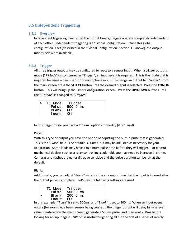
3.5.2 Trigger All three trigger outputs may be configured to react to a sensor input. When a trigger output’s mode (“T Mode”) is configured as “Trigger”, an input event is required. This is the mode that is required for using a beam sensor or microphone input. To change an output to “Trigger”, from the main screen press the SELECT button until the desired output is selected. Press the CONFIG button. This will bring up the Timer Configuration screen. Press the UP/DOWN buttons until the “T Mode” is changed to “Trigger”.
> T1 Mode: Trigger Pulse: 500.0 ms Blank: Off Incrm: Off
In this trigger mode you have additional options to modify (if required).
Pulse: With this type of output you have the option of adjusting the output pulse that is generated. This is the “Pulse” field. The default is 500ms, but may be adjusted as necessary for your application. Some loads may have a minimum pulse time before they will trigger. For electro‐mechanical devices such as a relay controlling a solenoid, you may need to increase this time. Cameras and flashes are generally edge sensitive and the pulse duration can be left at the default.
Blank: Additionally, you can adjust “Blank”, which is the amount of time that the input is ignored after the output pulse is complete. Let’s say the following settings are used:
T1 Mode: Trigger Pulse: 500.0 ms > Blank: 200.0 ms Incrm: Off
In this example, “Pulse” is set to 500ms, and “Blank” is set to 200ms. When an input event occurs (for example, a beam sensor being crossed), the trigger output will delay by whatever value is entered on the main screen, generate a 500ms pulse, and then wait 200ms before looking for an input again. “Blank” is useful for ignoring all but the first of a series of rapidly
occurring events. If the trigger output is being used to control a flash this allows time for it to fully charge before triggering again.
Incrm: This timer mode has the option to automatically increment the timer’s main delay every time an event occurs by adjusting the “Incrm” configuration. If an event is easily repeatable and this increment is set you can create a simulated “time lapse” for some quickly occurring event (like a drop of water falling).
If this value is set to 10.0 ms, and from the main screen the trigger output is set to 100.0 ms, every time a trigger occurs the delay would increase by 10ms. The delay setting will be updated on the main screen following each trigger event. The first time the trigger would wait 100 ms. The second: 110 ms. The third: 120 ms. Every time StopShot activates the trigger output the delay on the main screen will be incremented by the “Incrm” value. If you want to start the sequence over simply adjust the trigger output value on the main screen back to its original value using the UP/DOWN buttons.
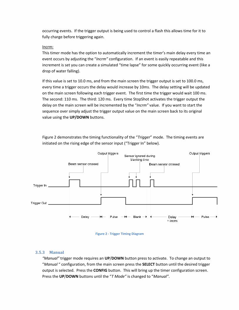
Figure 2 demonstrates the timing functionality of the “Trigger” mode. The timing events are initiated on the rising edge of the sensor input (“Trigger In” below).
Figure 2 ‐ Trigger Timing Diagram
3.5.3 Manual “Manual” trigger mode requires an UP/DOWN button press to activate. To change an output to “Manual “ configuration, from the main screen press the SELECT button until the desired trigger output is selected. Press the CONFIG button. This will bring up the timer configuration screen. Press the UP/DOWN buttons until the “T Mode” is changed to “Manual”.
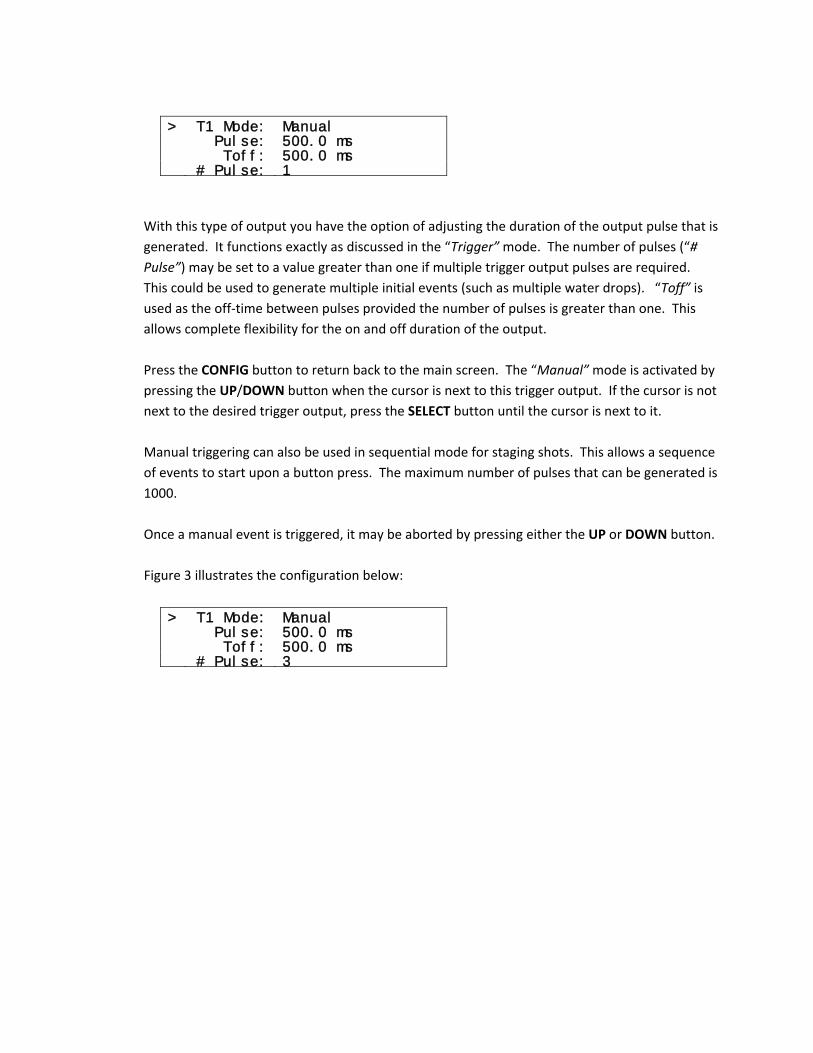
> T1 Mode: Manual Pulse: 500.0 ms Toff: 500.0 ms # Pulse: 1
With this type of output you have the option of adjusting the duration of the output pulse that is generated. It functions exactly as discussed in the “Trigger” mode. The number of pulses (“# Pulse”) may be set to a value greater than one if multiple trigger output pulses are required. This could be used to generate multiple initial events (such as multiple water drops). “Toff” is used as the off‐time between pulses provided the number of pulses is greater than one. This allows complete flexibility for the on and off duration of the output. Press the CONFIG button to return back to the main screen. The “Manual” mode is activated by pressing the UP/DOWN button when the cursor is next to this trigger output. If the cursor is not next to the desired trigger output, press the SELECT button until the cursor is next to it. Manual triggering can also be used in sequential mode for staging shots. This allows a sequence of events to start upon a button press. The maximum number of pulses that can be generated is 1000. Once a manual event is triggered, it may be aborted by pressing either the UP or DOWN button. Figure 3 illustrates the configuration below:
> T1 Mode: Manual Pulse: 500.0 ms Toff: 500.0 ms # Pulse: 3
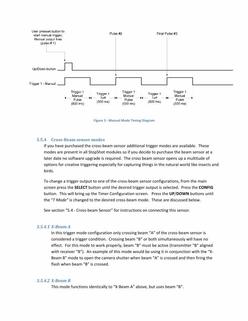
Figure 3 ‐ Manual Mode Timing Diagram
3.5.4 CrossBeam sensor modes If you have purchased the cross‐beam sensor additional trigger modes are available. These modes are present in all StopShot modules so if you decide to purchase the beam sensor at a later date no software upgrade is required. The cross beam sensor opens up a multitude of options for creative triggering especially for capturing things in the natural world like insects and birds.
To change a trigger output to one of the cross‐beam sensor configurations, from the main screen press the SELECT button until the desired trigger output is selected. Press the CONFIG button. This will bring up the Timer Configuration screen. Press the UP/DOWN buttons until the “T Mode” is changed to the desired cross‐beam mode. These are discussed below.
See section “5.4 ‐ Cross‐beam Sensor” for instructions on connecting this sensor.
3.5.4.1 XBeam A In this trigger mode configuration only crossing beam “A” of the cross‐beam sensor is considered a trigger condition. Crossing beam “B” or both simultaneously will have no effect. For this mode to work properly, beam “B” must be active (transmitter “B” aligned with receiver “B”). An example of this mode would be using it in conjunction with the “X‐Beam B” mode to open the camera shutter when beam “A” is crossed and then firing the flash when beam “B” is crossed.
3.5.4.2 XBeam B This mode functions identically to “X‐Beam A” above, but uses beam “B”.
3.5.4.3 XBeam a&b This is a true cross‐beam configuration. Both beams “A” and “B” must be broken simultaneously for a trigger condition to be considered valid. The main screen will display “XBS a&b” for this mode. Breaking only beam “A” or “B” will not be considered a input trigger. This mode is useful for detecting objects in a tightly controlled area (especially if lasers are used). The following configurations are available for this sensor:
> T1 Mode: X-Beam a&b Pulse: 500.0 ms Blank: 200.0 ms Incrm: Off These configurations function identically to the “Trigger” mode in section 3.5.2.
3.5.4.4 XBeam a|b In this configuration “A” or “B” will create a trigger condition for StopShot. The main screen will display “XBS a|b”. Use this sensor mode when it doesn’t matter which sensor is activated. The possible configurations for this mode are identical to the “X‐Beam a&b” mode.
3.5.4.5 XBeam a>b The main screen will display “XBS a‐>b” for this mode. Use this mode if you want to trigger on an object only moving in one direction. A good example would be capturing a bird entering a nest but not leaving. The configuration for this mode is shown below:
> T1 Mode: X-Beam a->b Pulse: 500.0 ms Blank: 200.0 ms Timeout: 250.0 ms
“Pulse” and “Blank” function the same as the previous modes (see section 3.5.2). “Timeout” is discussed below. When beam “A” is broken, the letter “a” in “XBS a‐>b” on the main screen will be capitalized (“XBS A‐>b”) to indicate that the “A” condition has been met and StopShot is waiting for the “B” condition. If the “B” beam is not broken prior to the configured “timeout” then the letter “A” will revert back to lower‐case indicating that StopShot is once again waiting for the “A” condition. This “timeout” option is a way for the trigger to re‐arm if event “B” never occurs. In the example of the bird entering a nest – If the bird flew close to the nest but did not land, it would allow StopShot to re‐arm the trigger output for the next time the bird would approach the nest.
3.5.4.6 XBeam b>a This mode functions the same as “X‐Beam a‐>b” but beam “B” must be broken first, followed by “A”. This allows direction reversal through the sensors without having to physically move them.
3.6 Sequential Triggering
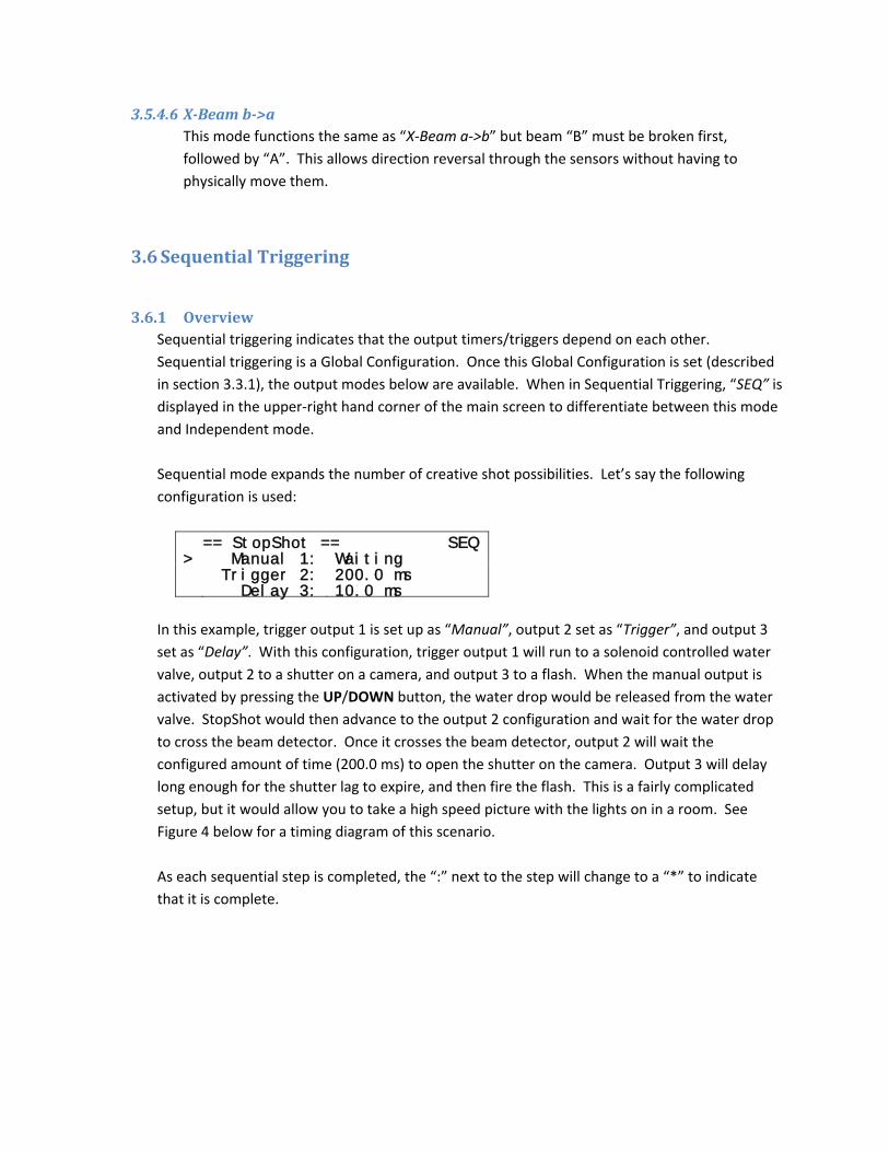
3.6.1 Overview Sequential triggering indicates that the output timers/triggers depend on each other. Sequential triggering is a Global Configuration. Once this Global Configuration is set (described in section 3.3.1), the output modes below are available. When in Sequential Triggering, “SEQ” is displayed in the upper‐right hand corner of the main screen to differentiate between this mode and Independent mode. Sequential mode expands the number of creative shot possibilities. Let’s say the following configuration is used:
== StopShot == SEQ > Manual 1: Waiting Trigger 2: 200.0 ms Delay 3: 10.0 ms
In this example, trigger output 1 is set up as “Manual”, output 2 set as “Trigger”, and output 3 set as “Delay”. With this configuration, trigger output 1 will run to a solenoid controlled water valve, output 2 to a shutter on a camera, and output 3 to a flash. When the manual output is activated by pressing the UP/DOWN button, the water drop would be released from the water valve. StopShot would then advance to the output 2 configuration and wait for the water drop to cross the beam detector. Once it crosses the beam detector, output 2 will wait the configured amount of time (200.0 ms) to open the shutter on the camera. Output 3 will delay long enough for the shutter lag to expire, and then fire the flash. This is a fairly complicated setup, but it would allow you to take a high speed picture with the lights on in a room. See Figure 4 below for a timing diagram of this scenario. As each sequential step is completed, the “:” next to the step will change to a “*” to indicate that it is complete.
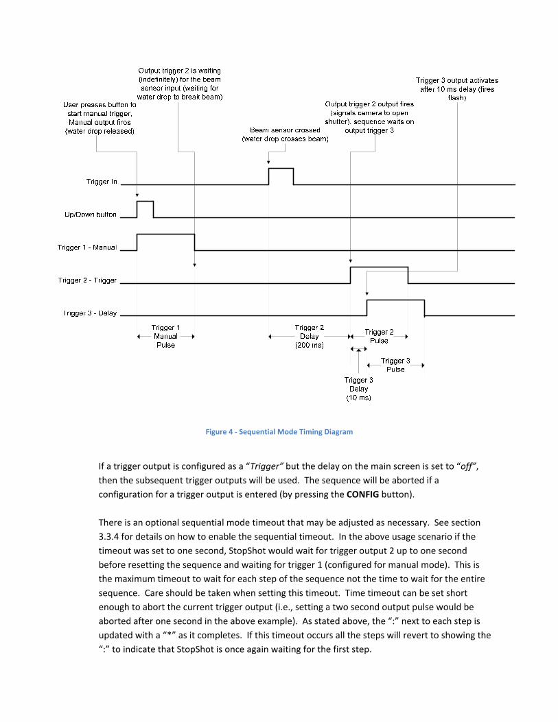
Figure 4 ‐ Sequential Mode Timing Diagram
If a trigger output is configured as a “Trigger” but the delay on the main screen is set to “off”, then the subsequent trigger outputs will be used. The sequence will be aborted if a configuration for a trigger output is entered (by pressing the CONFIG button). There is an optional sequential mode timeout that may be adjusted as necessary. See section 3.3.4 for details on how to enable the sequential timeout. In the above usage scenario if the timeout was set to one second, StopShot would wait for trigger output 2 up to one second before resetting the sequence and waiting for trigger 1 (configured for manual mode). This is the maximum timeout to wait for each step of the sequence not the time to wait for the entire sequence. Care should be taken when setting this timeout. Time timeout can be set short enough to abort the current trigger output (i.e., setting a two second output pulse would be aborted after one second in the above example). As stated above, the “:” next to each step is updated with a “*” as it completes. If this timeout occurs all the steps will revert to showing the “:” to indicate that StopShot is once again waiting for the first step.

3.6.2 Manual Trigger Manual triggering is discussed in the Independent Triggering section 3.5.3. While in Sequential Triggering, “Manual” mode is only available on trigger output 1. This allows trigger output 1 to function as the initiating condition (a button press) for a sequence of outputs.
3.6.3 Input Trigger The “Trigger” mode for Sequential Triggering functions exactly like the Independent Triggering mode. See the Independent Triggering section 3.5.2 for more details.
3.6.4 Delayed Trigger The “Delay” triggering configuration is only available in Sequential Triggering mode. It is a simple way to add a delay in activating the trigger output between steps. The “Delay” mode is not valid for the first trigger output since there is nothing to initiate the sequence of events. To change an output mode to “Delay”, from the main screen press the SELECT button until trigger output 2 or 3 is selected. Press the CONFIG button. This will bring up the configuration screen for the specific trigger output. Press the UP/DOWN buttons until the “T Mode” is changed to “Delay”.
> T2 Mode: Delay Pulse: 500.0 ms Incrm: off Sync: No
Just like the independent “Trigger” mode you have the option of adjusting “Pulse” and “Incrm” as needed. An additional configuration is “Sync”. When “Sync” is set to “No”, the delay time will start from the falling edge of the previous trigger output (it starts after the trigger output LED is off – so after the “Pulse” time has expired). If “Sync” is set to “Yes”, it will start from the rising edge of the previous trigger output (the moment the output LED turns on). “Figure 5 ‐ Delay Synchronization” below is using the following configuration:
== StopShot == SEQ > Trigger 1: 100.0 ms Delay 2: 250.0 ms Trigger 3: Off
Note the behavior difference of “Delay 2” when “Trigger 1” changes its output.
Trigger 1 - Trigger
Beam sensor is crossed
Beam sensor
Trigger 1Pulse
(500 ms)
Trigger 1 100 ms
Trigger 2 - Delay
Delay 2:250 ms
Delay 2Pulse
(500 ms)
Delay – Sync = No
Trigger 1 - Trigger
Beam sensor is crossed
Beam sensor
Trigger 1Pulse
(500 ms)
Trigger 1 100 ms
Trigger 2 - Delay
Delay 2:250 ms
Delay 2Pulse
(500 ms)
Delay – Sync = Yes
Figure 5 ‐ Delay Synchronization
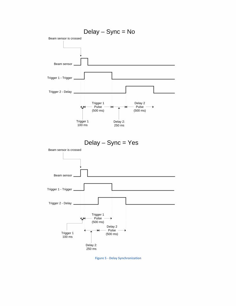
3.7 TimeLapse Time Lapse is another available “Global Configuration”. Once this global configuration is selected (described in the “Global Configuration” section 3.3.1) Time Lapse mode will be enabled. This is useful for creating a series of shots for something that changes slowly: A sunrise, clouds traversing the sky, plants growing, or even congress voting. The time‐lapse interval is adjusted via the main screen using the UP/DOWN buttons. See the example settings below:
== StopShot == > TLapse 1: 2.0 sec Remaining: 1.9 sec Count: 3
You also have the option to adjust the “Pulse” configuration. Like other modes, press the CONFIG button. It will bring up the following configuration screen:
TLapse Config: > Pulse: 500.0 ms
In this example, the “Pulse” configuration is left at the default of 500.0 ms, and the interval delay is set to two seconds (on the main screen). Since the two seconds is the time between the pulses, there would be 2.0 seconds (interval time on the main screen) plus the 0.500 seconds (“Pulse”), for a total of 2.50 seconds between pictures. As shown in the above display, Time Lapse mode will show the remaining time before the next trigger event (“Remaining”) and also the number of times (“Count”) that the trigger output has fired. “Count” will limit itself at 9,999 trigger events. See Figure 6 for a timing diagram. Only trigger output 1 is used for Time Lapse mode.

Figure 6 ‐ Time Lapse Timing Diagram
3.8 Flash Duration Measurement StopShot and its infrared beam sensor receiver may be used to measure the duration of a flash. To configure StopShot to measure the duration of a flash press and hold the CONFIG button for two seconds until the global configuration screen appears. Press SELECT until “TMode” is selected. Use the UP/DOWN buttons until “TMode” changes to “F Duration”.
== Global Config == > TMode: F Duration
LCD Backlight: 10 Load Defaults:
Press the CONFIG button to return to the main screen. You will see the following on the display indicating StopShot is waiting for a flash input:
Up/down to start Flash Measurement Duration: Waiting
If the gain knob is set too high, it is possible for ambient light to falsely trigger the flash measurement. Adjust the gain to the middle position as this will prevent StopShot from triggering in ambient light. Fire the flash at least 12 inches (30 cm) away from the infrared sensor receiver. To get an accurate reading it is important that the sensor does not become saturated (too much light). If this happens your measurement will be artificially long. Do not point the flash directly at the sensor. StopShot is sensitive enough to capture the initial high‐voltage trigger pulse used to light a xenon tube. If you see measurements less than one microsecond you are likely measuring this fast trigger pulse. Point the flash further away from StopShot if you run into this condition. The display will show the resulting flash duration measurement:
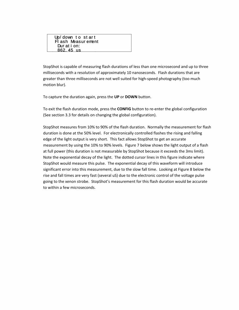
Up/down to start Flash Measurement Duration: 862.45 us
StopShot is capable of measuring flash durations of less than one microsecond and up to three milliseconds with a resolution of approximately 10 nanoseconds. Flash durations that are greater than three milliseconds are not well suited for high‐speed photography (too much motion blur). To capture the duration again, press the UP or DOWN button. To exit the flash duration mode, press the CONFIG button to re‐enter the global configuration (See section 3.3 for details on changing the global configuration). StopShot measures from 10% to 90% of the flash duration. Normally the measurement for flash duration is done at the 50% level. For electronically controlled flashes the rising and falling edge of the light output is very short. This fact allows StopShot to get an accurate measurement by using the 10% to 90% levels. Figure 7 below shows the light output of a flash at full power (this duration is not measurable by StopShot because it exceeds the 3ms limit). Note the exponential decay of the light. The dotted cursor lines in this figure indicate where StopShot would measure this pulse. The exponential decay of this waveform will introduce significant error into this measurement, due to the slow fall time. Looking at Figure 8 below the rise and fall times are very fast (several uS) due to the electronic control of the voltage pulse going to the xenon strobe. StopShot’s measurement for this flash duration would be accurate to within a few microseconds.

Figure 7 ‐ Full Power Flash Output
Figure 8 below shows the same flash unit at sixteenth power.
Figure 8 ‐ Sixteenth Power Flash Output

4. Accessories
IR Beam Sensor [IR_S02]
This IR (infrared) Curtain for STOP SHOT contains both an IR transmitter and receiver. It can be used to capture anything that moves between the elements. It works great for water drops and ballistics. It is sensitive enough to be triggered by a .22 caliber bullet. The sensor’s oak base is designed to be mounted on a standard 1/2" pipe clamp. Shown to the right is a focusing lens (not included) to improve the range of the infrared beam. This lens should not be used when the sensors are close together as it will saturate the receiver and negatively impact the sensitivity. The transmitter for this sensor has a switch to adjust the power output. The low setting should be selected when the sensor is used on the provided oak stand. This setting will maximize sensitivity at this short distance. If the sensor is used with more distance between the elements the switch can be moved to the high power setting to increase the range. This is the senor that is included with the deluxe package.
Infrared Beam Sensor ‐ Transmitter/Receiver Specifications Min Typical Max Units Input Voltage (Transmitter) 4.0 4.5 5.0 V IR Transmitter Current 47 mA Range (no lens) 1.0 Ft Range (with lens) 6ft Ft
Features:
• Invisible beam will not show in pictures
• Great for water‐drops and ballistics
• May be used to measure flash duration
• Excellent sensitivity
• Adjustable power
• Focusing lens available
• 6 ft ( 1.8 m) IR range (with optional lens)
• 6 ft 3.5mm and 6 ft 2.5mm cable included

Cross‐Beam Infrared Transmitter/Receiver [XBS_IR01]
Cross beam sensors add a whole new dimension to your triggering capability (literally). They work excellent for subjects whose trajectories are not as defined as water drops or projectiles. This cross beam sensor was designed for capturing images of insects, birds, and other less predictable creatures. See section 3.5.4 for all of the different triggering modes for these sensors.
Receiver A includes a tri‐colored LED (mounted on the back) to indicate when each receiver is lined up correctly. See section 5.4 for details. The infrared version of this sensor has the advantage of having an invisible beam (unlike the red laser light). The disadvantage of IR is the beam size is larger. The larger beam size can be mitigated somewhat by using an aperture in front of the receiver. A lens (included as shown above) on the IR transmitters will yield a range in excess of six feet. For short distances the lens should be removed. The lens focuses the IR beam and if it remains attached at short distances it will saturate the receiver with IR light. This may cause the receiver to not detect small objects crossing the beam. Oak base not included.
Cross‐Beam Infrared Transmitter/Receiver Specifications Min Typical Max Units Input Voltage 4.0 4.5 5.0 V Output Voltage Vin V IR Transmitter Current 47 mA Total Current 100 mA
• Two transmitters and two receivers
• 6+ feet (182 cm) IR range
• Dual‐axis triggering
• Conditional triggering (A followed by B, but within a certain time)
• Optional tripod mount available for sensors
• LED indicator for incident light on receivers
• Two 6 ft 3.5mm and two 6 ft 2.5 mm cables included.
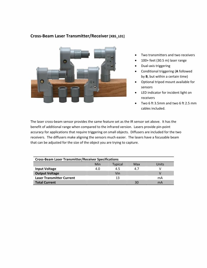
Cross‐Beam Laser Transmitter/Receiver [XBS_L01]
The laser cross‐beam sensor provides the same feature set as the IR sensor set above. It has the benefit of additional range when compared to the infrared version. Lasers provide pin‐point accuracy for applications that require triggering on small objects. Diffusers are included for the two receivers. The diffusers make aligning the sensors much easier. The lasers have a focusable beam that can be adjusted for the size of the object you are trying to capture.
Cross‐Beam Laser Transmitter/Receiver Specifications Min Typical Max Units Input Voltage 4.0 4.5 4.7 V Output Voltage Vin V Laser Transmitter Current 13 mA Total Current 30 mA
• Two transmitters and two receivers
• 100+ feet (30.5 m) laser range
• Dual‐axis triggering
• Conditional triggering (A followed by B, but within a certain time)
• Optional tripod mount available for sensors
• LED indicator for incident light on receivers
• Two 6 ft 3.5mm and two 6 ft 2.5 mm cables included.

Beam Receiver [RCVR_02]
This sensor is the receiver half of the Beam Sensor. It can be used with an IR or Laser transmitter. Use with LSR_TMTR_01, shown below.
Why would you need a replacement infrared sensor? The most likely answer: Ballistics photography gone wrong. We wouldn’t admit to accidentally shooting a sensor either. Your secret is safe with us.
Features:
• 6 ft ( 1.8 m) IR range
• 100+ ft (30.5 m) laser range
• May be used with Laser or IR transmitters
• Available with oak base or ¼” tripod mount
• May be used to measure flash duration
• Includes laser diffuser
• 6 ft 3.5mm cable included
• 4.06” x 2.47” x 1.37” (10.31cm x 6.27cm x 3.73cm)
When using the laser transmitter the diffuser will prevent small movements of the receiver or the “speckle” in a laser beam from falsely triggering StopShot. What’s “speckle”? It’s a phenomenon that occurs in lasers when a correlated light beam experiences interference from waves with different phases. This is often noticed when shining a laser on a surface – It seems to shift and twinkle on its own. Imperfections in the surface can cause the laser light to slightly phase shift resulting in a variance in amplitude. The diffuser also reduces the alignment precision between the transmitter and receiver.

Laser Transmitter ‐ [LSR_TMTR_01]
Laser Transmitter Features:
• Long Range (100+ ft)
• Available with oak base or ¼” tripod mount (optional bases available)
• 2.5mm Power Jack
• Battery Pack available for Power
• Focusable beam (hand‐adjusted)
• 5mW laser Class II Laser Beam
• 960 nm wavelength (red)
• 13mA @ 4.5V
• 6 ft 2.5mm cable included
• 4.06” x 3.40” x 1.37” (10.31cm x 8.64cm x 3.73cm)
Never look into the laser beam, shine it at someone else, or reflect it off a surface that could bounce back into your (or others) eyes. Laser light damages eyes – which would defeat the purpose of photography.
The laser transmitter is very effective at aiding in the capture of small or very high speed objects. It is also a great way to increase the range between the transmitter and receiver. This makes it very suitable for capturing elusive wildlife such as deer – not that they are small or very high speed.
The laser transmitter contains an adjustable lens to focus the beam. When triggering on extremely small objects it is desirable to focus the laser to a narrow beam. Detection of 1 – 2 mm objects is possible.
Laser Transmitter Specifications Min Typical Max Units Operating Voltage 4.0 4.5 4.7 V Current Draw 13 mA Laser Power 5 mW Beam wavelength 960 nm
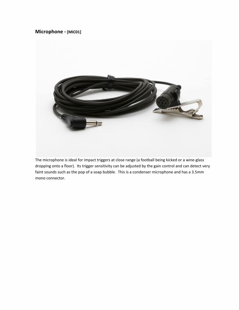
Microphone ‐ [MIC01]
The microphone is ideal for impact triggers at close range (a football being kicked or a wine‐glass dropping onto a floor). Its trigger sensitivity can be adjusted by the gain control and can detect very faint sounds such as the pop of a soap bubble. This is a condenser microphone and has a 3.5mm mono connector.

Battery Pack for Laser/IR Transmitter ‐ [BAT_PAK_01]
Battery Pack Features:
• Holds 3 AA Batteries (Alkaline recommended)
• On/off switch
• Includes a 3ft cable with a 2.5mm plug (fits Laser and IR transmitters)
• 130+ hour life for laser transmitters
• 50+ hour life Infrared transmitters
• 2.72” x 1.90” x 0.72” (6.90cm x 4.83cm x 1.83cm)
• Short‐circuit battery protection
Make sure this battery pack is switched off when not connected to a laser sensor. If the 2.5mm plug is shorted out excessive heat may be generated and battery life with be greatly diminished.
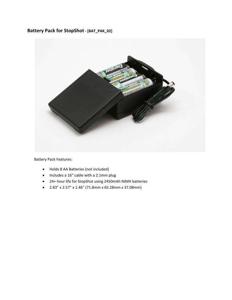
Battery Pack for StopShot ‐ [BAT_PAK_02]
Battery Pack Features:
• Holds 8 AA Batteries (not included)
• Includes a 16” cable with a 2.1mm plug
• 24+ hour life for StopShot using 2450mAh NiMH batteries
• 2.83” x 2.57” x 1.46” (71.8mm x 65.28mm x 37.08mm)
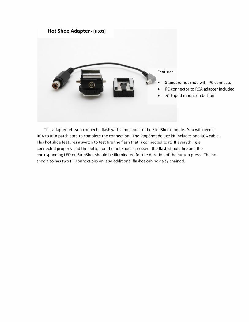
Hot Shoe Adapter ‐ [HS01]
Features:
• Standard hot shoe with PC connector
• PC connector to RCA adapter included
• ¼” tripod mount on bottom
This adapter lets you connect a flash with a hot shoe to the StopShot module. You will need a RCA to RCA patch cord to complete the connection. The StopShot deluxe kit includes one RCA cable. This hot shoe features a switch to test fire the flash that is connected to it. If everything is connected properly and the button on the hot shoe is pressed, the flash should fire and the corresponding LED on StopShot should be illuminated for the duration of the button press. The hot shoe also has two PC connections on it so additional flashes can be daisy chained.

Water Valve Assembly ‐ [WVA01]
• Fully controllable via StopShot
• 12V DC Power
• 3/8” barb
• Mounting screw holes
Great for water drop photos. This valve assembly can be connected directly to StopShot to create precision controlled drops of water. This valve was used to create many of the "drop crashing into drop" photos in our gallery. It includes a power supply and the cable assembly required to connect it to StopShot.
This valve has a very good response time. When being driven by StopShot this valve is capable of delivering a drop of water with a 30mS pulse. StopShot may be configured to put virtually any delay between drops giving you maximum flexibility when trying to capture water drop photos.
The barbs on this valve are 3/8 inch, and it is powered by 12VDC (supply included). 3/8 inch inside‐diameter (3/8” ID) clear tubing is available from your local hardware store.
This valve is also available without the power supply. See the StopShot Shop on our website for details.
5. Connections & Cables One of the design goals of StopShot was to make it simple to add cable extensions and do custom wiring. Nothing is more frustrating than buying a product and finding out that it uses over‐priced proprietary cables. All StopShot cables are available at your favorite audio/video equipment supply store. We provide the connection diagrams below so that you have the option of making custom cables or sensors. If you have any questions, please contact us at support@cognisys‐inc.com.
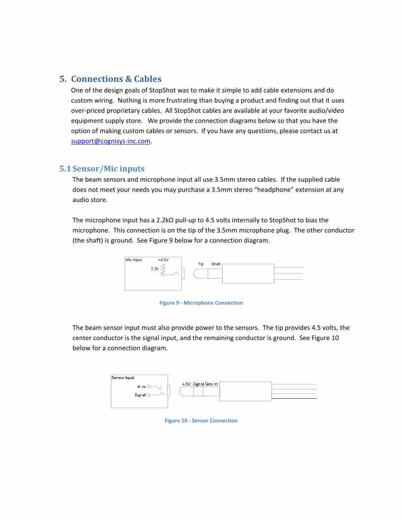
5.1 Sensor/Mic inputs The beam sensors and microphone input all use 3.5mm stereo cables. If the supplied cable does not meet your needs you may purchase a 3.5mm stereo “headphone” extension at any audio store. The microphone input has a 2.2kΩ pull‐up to 4.5 volts internally to StopShot to bias the microphone. This connection is on the tip of the 3.5mm microphone plug. The other conductor (the shaft) is ground. See Figure 9 below for a connection diagram.
Mic Input +4.5V
2.2kTip Shaft
Figure 9 ‐ Microphone Connection
The beam sensor input must also provide power to the sensors. The tip provides 4.5 volts, the center conductor is the signal input, and the remaining conductor is ground. See Figure 10 below for a connection diagram.
Figure 10 ‐ Sensor Connection

5.2 Trigger Outputs All the trigger outputs use standard “RCA” jacks. RCA extensions come in all different types, one end as male and the other as female. There are mono (single) extensions which are typically used for video. Stereo/dual extensions are usually for extending audio connections. There are triple extensions for extending audio and video equipment. You also have the option of buying standard RCA cables and using a coupler adapter to connect two male/male cables together. As with all RCA jacks the outside connector is ground. StopShot outputs are “Low Side Drivers” (switches in ground). This means that when a trigger output fires, it connects the center conductor of the RCA jack to the outside connector (ground) to draw current through the center conductor. See Figure 11 below for a wiring diagram for the RCA connectors.
StopShot Output
Outside RCA terminal
Inside RCA terminal
Figure 11 ‐ RCA connector
5.3 Activating Relays Some applications require activating a relay to enable (or disable) a “load”. Relays allow StopShot to turn on/off a variety of AC and DC devices.
CAUTION: Care should be taken when wiring up StopShot to control AC or high‐voltage DC as a mistake in wiring the relay could cause damage to StopShot and other connected devices. See Figure 12 below as an example of wiring StopShot to control a 12V DC relay.
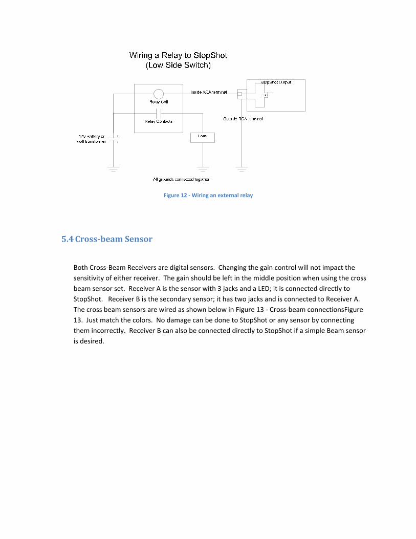
Figure 12 ‐ Wiring an external relay
5.4 Crossbeam Sensor
Both Cross‐Beam Receivers are digital sensors. Changing the gain control will not impact the sensitivity of either receiver. The gain should be left in the middle position when using the cross beam sensor set. Receiver A is the sensor with 3 jacks and a LED; it is connected directly to StopShot. Receiver B is the secondary sensor; it has two jacks and is connected to Receiver A. The cross beam sensors are wired as shown below in Figure 13 ‐ Cross‐beam connectionsFigure 13. Just match the colors. No damage can be done to StopShot or any sensor by connecting them incorrectly. Receiver B can also be connected directly to StopShot if a simple Beam sensor is desired.
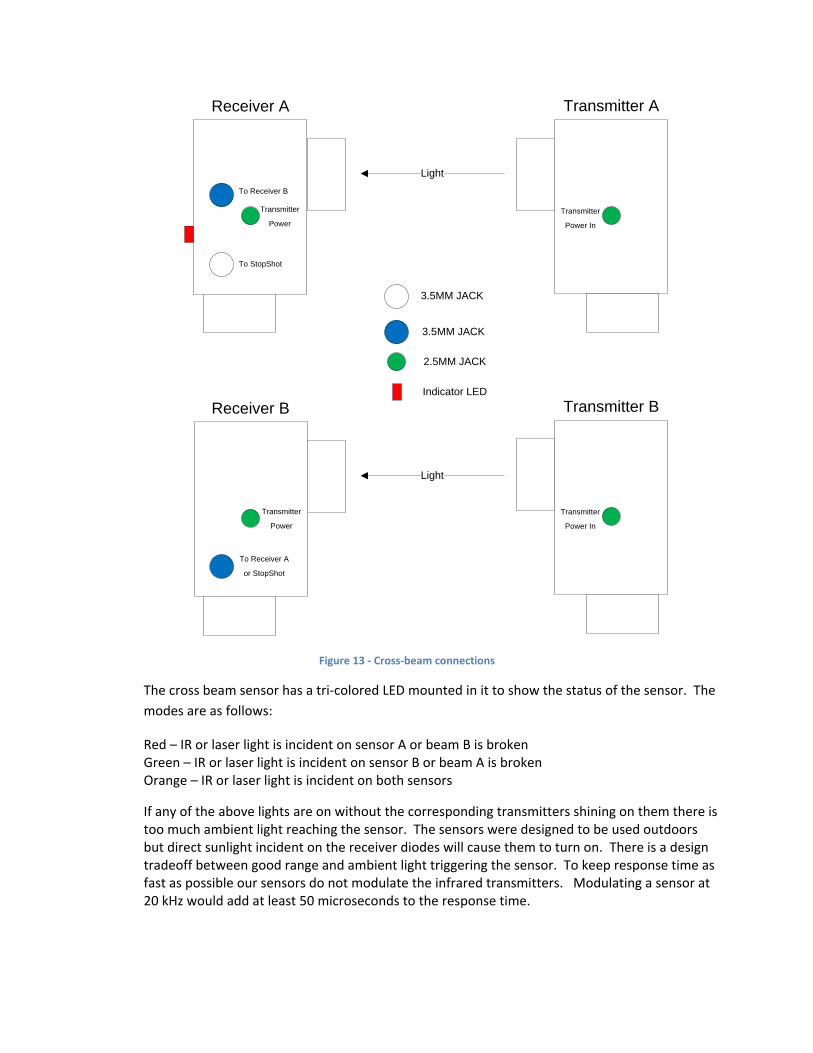
3.5MM JACK
2.5MM JACK
Indicator LED
3.5MM JACK
Receiver A
To StopShot
To Receiver B
Transmitter
Power
Receiver B
To Receiver A
or StopShot
Transmitter
Power
Transmitter A
Transmitter
Power In
Transmitter B
Transmitter
Power In
Light
Light
Figure 13 ‐ Cross‐beam connections
The cross beam sensor has a tri‐colored LED mounted in it to show the status of the sensor. The modes are as follows:
Red – IR or laser light is incident on sensor A or beam B is broken Green – IR or laser light is incident on sensor B or beam A is broken Orange – IR or laser light is incident on both sensors
If any of the above lights are on without the corresponding transmitters shining on them there is too much ambient light reaching the sensor. The sensors were designed to be used outdoors but direct sunlight incident on the receiver diodes will cause them to turn on. There is a design tradeoff between good range and ambient light triggering the sensor. To keep response time as fast as possible our sensors do not modulate the infrared transmitters. Modulating a sensor at 20 kHz would add at least 50 microseconds to the response time.

When using lasers as the cross beam transmitters it is best to use the included diffuser (Figure 14) over the both sensors. The diffuser will allow much easier alignment of the laser beams. It will also prevent small movements of either the sensor or the transmitter from causing false triggers. The laser transmitter contains an adjustable lens to focus the beam. When triggering on extremely small objects it is desirable to focus the laser to a narrow beam. Detection of 1 – 2 mm objects is possible.
When using IR transmitters do not use the diffuser as it will attenuate the light too much and seriously degrade range.
Figure 14 ‐ Laser Diffuser
Below are some general guidelines for using the sensors:
The sensors work by changes in light produced by objects passing between the transmitter (source) and the sensor (receiver). The object you are trying to capture essentially has to cast a shadow over the small light sensing pin diode internal to the sensor. The diode can be seen inside the sensor (a small black shiny part). If you are trying to capture small objects it is best if the object passes between the receiver and the transmitter as close to the receiver as possible. If you are having trouble triggering on extremely small objects (i.e. 1 ‐2 mm flying insects) it may be necessary to place a small aperture in front of the sensor. Make the aperture as small as possible while maintaining the sensor active light on. The diameter of the aperture will need to be large enough to let enough light reach the photodiode to turn on the photodiode. This diameter will be a function of distance to the transmitter. This technique is more useful for the IR sensor; the laser beam is already very narrow. If using the laser beams be sure to adjust the beam width for your application using the focusing lens and the end of the transmitters.
6. Trouble Triggering
If there is an idea for a picture that you want to take but can’t quite figure out how to make it happen, e‐mail us at support@cognisys‐inc.com. It doesn’t matter how bizarre it is – we might be able to come up with a way to make it happen. If it requires a new feature in StopShot and you are the first one to request it, we’ll reprogram your module for free! Just be sure to send us your final picture – we like to see how our product is being used.
7. Setup examples (getting the ultimate shot)
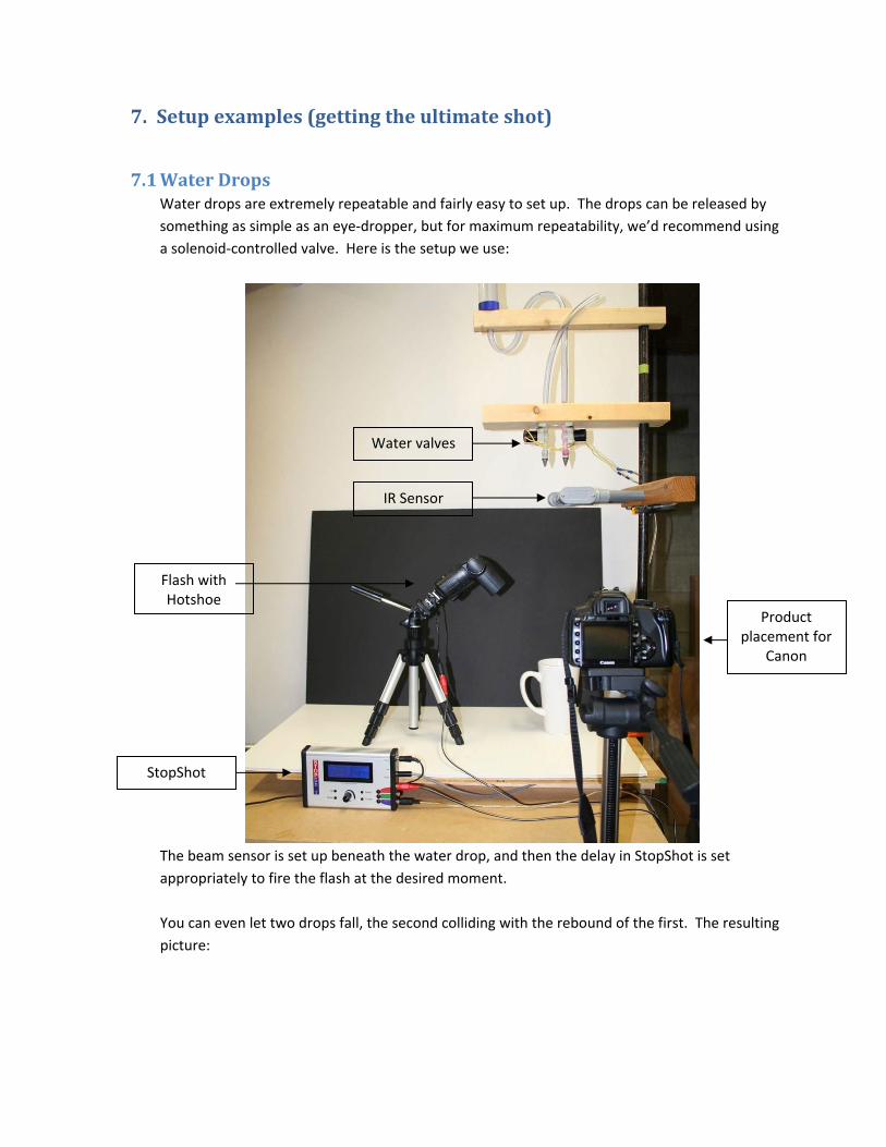
7.1 Water Drops Water drops are extremely repeatable and fairly easy to set up. The drops can be released by something as simple as an eye‐dropper, but for maximum repeatability, we’d recommend using a solenoid‐controlled valve. Here is the setup we use:
The beam sensor is set up beneath the water drop, and then the delay in StopShot is set appropriately to fire the flash at the desired moment. You can even let two drops fall, the second colliding with the rebound of the first. The resulting picture:
Water valves
IR Sensor
StopShot
Flash with Hotshoe
Product placement for
Canon

The water drop falls into a small amount of water inside a glass container. The image beneath the glass is distorted from the waves in the water and also reflected in the drop itself. The depth of the water also affects the rebound and ripple. Try variations – the possible pictures are limitless. Most importantly: Have fun! With free‐falling objects (including water drops), you can use the following formula to estimate the distance travelled, or solving for “t”, the time required from the beam sensor to impact. x = ½ at2 x = the distance traveled a = acceleration constant of gravity, 32 ft/second2 for a result in feet, or 9.8 m/second2 for
meters. t = time in seconds So if the water drop will fall 16 inches to the surface of the water: 16 / 12 = 1.33 feet 1.33 = ½ (32) t2

t2 = 0.083125 ‐‐ divide 1.33 by (½ * 32) to get t2 by itself t = 0.2883 ‐‐ Take the square root of 0.083125 So for a water drop to fall 16 inches, it will take 288.3 milliseconds. The purists out there will note that we’re not accounting for air resistance. We’ll just call it negligible for this distance.
7.2 Ballistics – Tips and Tricks
First we would recommend using the IR light curtain or the laser beam for high‐speed ballistics instead of the microphone. There is a surprisingly large amount of variability in timing when using audio (at 1,200 feet per second – a millisecond goes a long ways!).
Use or make a large card‐board box to contain whatever you plan to shoot. Cut a small hole for your camera, but protect the lens with a piece of Plexiglas. The box serves a couple of purposes, the first is to keep out unwanted light and the second is to contain the mess from whatever you are shooting. The flash should also be protected. Always be aware of your surroundings and who or what is down range. Safety first!
Using a reflective surface on the inside of the box will improve the lighting conditions of the target object. The backdrop for the object will vary depending on what is being shot. If there is a spray of moisture (fruit, vegetables, etc), a black background may be required to see the droplets.
For Ballistics shots like this we built a fixture for the rifle. A fixture makes both hitting the target and triggering StopShot very repeatable. This picture was taken with a Xenon flash (duration = 2uS).
Figure 15 ‐ A Sucker being Shot with a .22 Caliber Rifle
WARNING: Always use a remote trigger for your camera (wired or wireless) when shooting ballistics photos. Never stand down range from any loaded gun. Seriously. We like repeat customers.

8. Animated TimeLapse movies By using the “Time Lapse” global configuration you can generate a sequence of pictures. There are some freely available programs that can convert a series of JPEG pictures into an MPEG or AVI movie. For information on these programs and the latest links to the software, please visit our website at: http://www.cognisys‐inc.com.
When taking a series of time‐lapse pictures, you may or may not want to disable the auto‐exposure feature of your camera. If capturing a sunset, you may want the light to progressively dwindle into nothing, instead of the camera increasing the exposure time to compensate for the low‐light. Some experimentation may be required.
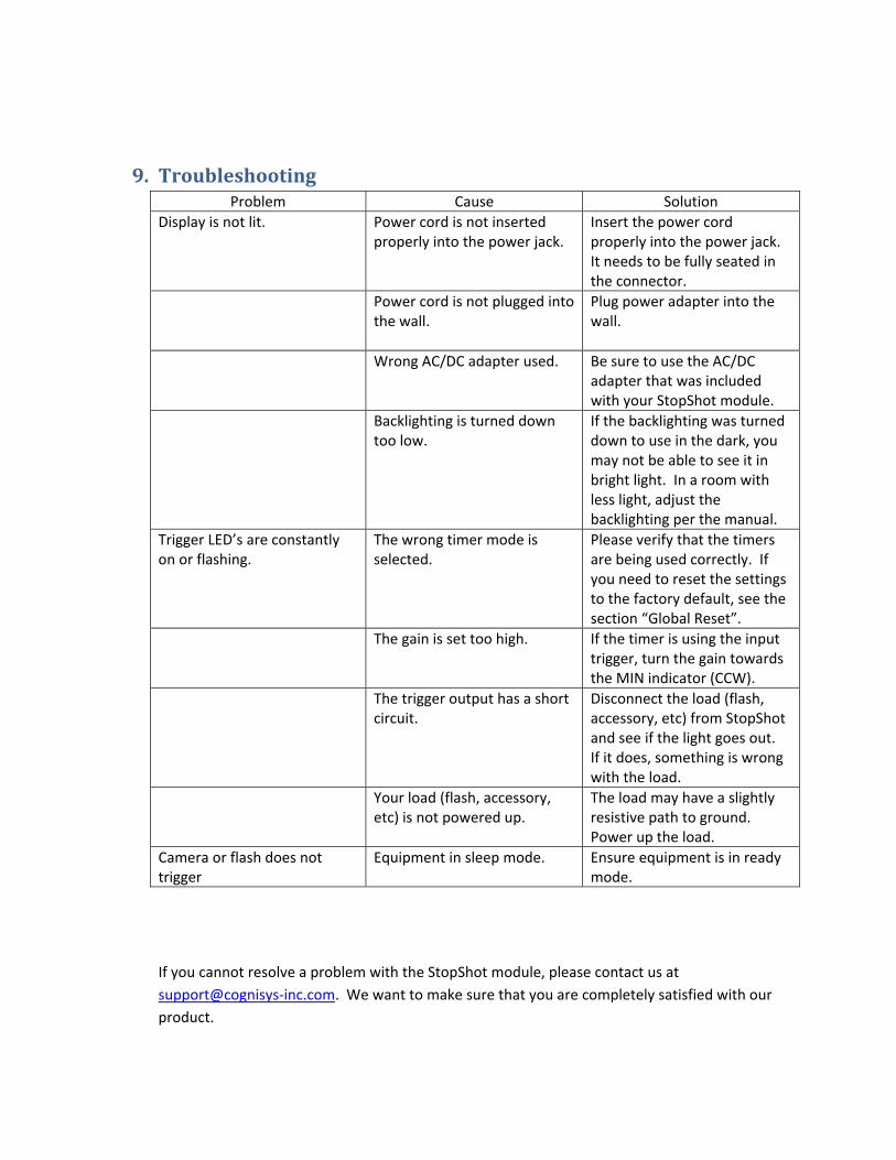
9. Troubleshooting Problem Cause Solution
Display is not lit. Power cord is not inserted properly into the power jack.
Insert the power cord properly into the power jack. It needs to be fully seated in the connector.
Power cord is not plugged into the wall.
Plug power adapter into the wall.
Wrong AC/DC adapter used. Be sure to use the AC/DC adapter that was included with your StopShot module.
Backlighting is turned down too low.
If the backlighting was turned down to use in the dark, you may not be able to see it in bright light. In a room with less light, adjust the backlighting per the manual.
Trigger LED’s are constantly on or flashing.
The wrong timer mode is selected.
Please verify that the timers are being used correctly. If you need to reset the settings to the factory default, see the section “Global Reset”.
The gain is set too high. If the timer is using the input trigger, turn the gain towards the MIN indicator (CCW).
The trigger output has a short circuit.
Disconnect the load (flash, accessory, etc) from StopShot and see if the light goes out. If it does, something is wrong with the load.
Your load (flash, accessory, etc) is not powered up.
The load may have a slightly resistive path to ground. Power up the load.
Camera or flash does not trigger
Equipment in sleep mode. Ensure equipment is in ready mode.
If you cannot resolve a problem with the StopShot module, please contact us at support@cognisys‐inc.com. We want to make sure that you are completely satisfied with our product.
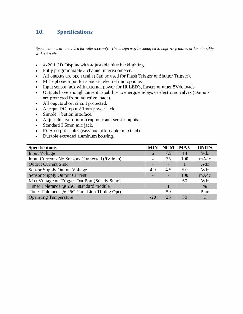
10. Specifications
Specifications are intended for reference only. The design may be modified to improve features or functionality without notice.
• 4x20 LCD Display with adjustable blue backlighting. • Fully programmable 3 channel intervalometer. • All outputs are open drain (Can be used for Flash Trigger or Shutter Trigger). • Microphone Input for standard electret microphone. • Input sensor jack with external power for IR LED's, Lasers or other 5Vdc loads. • Outputs have enough current capability to energize relays or electronic valves (Outputs
are protected from inductive loads). • All ouputs short circuit protected. • Accepts DC Input 2.1mm power jack. • Simple 4 button interface. • Adjustable gain for microphone and sensor inputs. • Standard 3.5mm mic jack. • RCA output cables (easy and affordable to extend). • Durable extruded aluminum housing.
Specifications MIN NOM MAX UNITS Input Voltage 6 7.5 14 Vdc Input Current - No Sensors Connected (9Vdc in) - 75 100 mAdc Output Current Sink - - 1 Adc Sensor Supply Output Voltage 4.0 4.5 5.0 Vdc Sensor Supply Output Current - - 100 mAdc Max Voltage on Trigger Out Port (Steady State) - - 60 Vdc Timer Tolerance @ 25C (standard module) 1 % Timer Tolerance @ 25C (Precision Timing Opt) 50 Ppm Operating Temperature -20 25 50 C

11. Warranty
Limited Warranty
All products are warranted to be free from defects in materials or workmanship for one (1) year from the date of purchase. Within this period, Cognisys Inc. will, at its sole option, repair or replace any components which fail in normal use. Such repairs or replacement will be made at no charge to the customer for parts or labor, provided that the customer shall be responsible for any transportation cost. This warranty does not cover failures due to abuse, misuse, accident or unauthorized alterations or repairs.
THE WARRANTIES AND REMEDIES CONTAINED HEREIN ARE EXCLUSIVE AND IN LIEU OF ALL OTHER WARRANTIES, WHETHER EXPRESS, IMPLIED OR STATUTORY, INCLUDING ANY LIABILITY ARISING UNDER ANY WARRANTY OF MERCHANTABILITY OR FITNESS FOR A PARTICULAR PURPOSE, STATUTORY OR OTHERWISE. THIS WARRANTY GIVES YOU SPECIFIC LEGAL RIGHTS, WHICH MAY VARY FROM STATE TO STATE.
IN NO EVENT SHALL COGNISYS BE LIABLE FOR ANY INCIDENTAL, SPECIAL, INDIRECT OR CONSEQUENTIAL DAMAGES, WHETHER RESULTING FROM THE USE, MISUSE OR INABILITY TO USE THE PRODUCT OR FROM DEFECTS IN THE PRODUCT. SOME STATES DO NOT ALLOW THE EXCLUSION OF INCIDENTAL OR CONSEQUENTIAL DAMAGES, SO THE ABOVE LIMITATIONS MAY NOT APPLY TO YOU.
Cognisys retains the exclusive right to repair or replace the product or offer a full refund of the purchase price at its sole discretion. SUCH REMEDY SHALL BE YOUR SOLE AND EXCLUSIVE REMEDY FOR ANY BREACH OF WARRANTY.

12. Revision History
Revision Date Change 1.0 6/2/08 Initial Release 1.1 11/21/08 Updated product portfolio and additional sensor modes. 1.2 12/19/08 Added X‐beam A/B mode, sequential mode timeout, and StopShot battery pack.
TX power switch added to IR beam sensor.

![PFI brochure [PDF - 1.3MB]](https://static.fdocuments.in/doc/165x107/586a1ccd1a28ab847d8bcc1c/pfi-brochure-pdf-13mb.jpg)


![Introduction to the SAAT presentation [1.3Mb]](https://static.fdocuments.in/doc/165x107/555988cad8b42ac7648b480d/introduction-to-the-saat-presentation-13mb.jpg)