Version 1 - HBX Control Systems · HBX Control Systems Inc. Installation Manual THM-0100 Setpoint...
16
HBX Control Systems Inc. Installation Manual THM-0100 Setpoint Thermostat Version 1.041 THM-0100
Transcript of Version 1 - HBX Control Systems · HBX Control Systems Inc. Installation Manual THM-0100 Setpoint...

HBX Control Systems Inc.
Installation ManualTHM-0100 Setpoint Thermostat
Version 1.041
THM-0100
© 2014 HBX Controls2
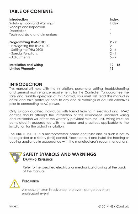
INTRODUCTIONThis manual will help with the installation, parameter setting, troubleshooting and general maintenance requirements for the Controller. To guarantee the safe and reliable operation of this Control, you must first read this manual in detail and take particular note to any and all warnings or caution directives prior to connecting to AC power.
Only suitably qualified individuals with formal training in electrical and HVAC controls should attempt the installation of this equipment. Incorrect wiring and installation will affect the warranty provided with this unit. Wiring must be completed in accordance with the codes and practices applicable to the jurisdiction for the actual installation.
The HBX THM-0100 is a microprocessor based controller and as such is not to be regarded as a safety (limit) control. Please consult and install the heating or cooling appliance in accordance with the manufacturer’s recommendations.
SAFETY SYMBOLS AND WARNINGS Drawing reference
Refer to the specified electrical or mechanical drawing at the back of the manual.
Precaution
A measure taken in advance to prevent dangerous or an unpleasant event
TABLE OF CONTENTSIntroduction IndexSafety symbols and Warnings IndexReceipt and Inspection 1Description 1Technical data and dimensions 1
Programming THM-0100 2 - 9- Navigating the THM-0100 2- Setting the THM-0100 2 - 4- Special Functions 2 - 4- Adjustments 5 - 9
Installation and Wiring 10 - 12Limited Warranty 13
Index
1
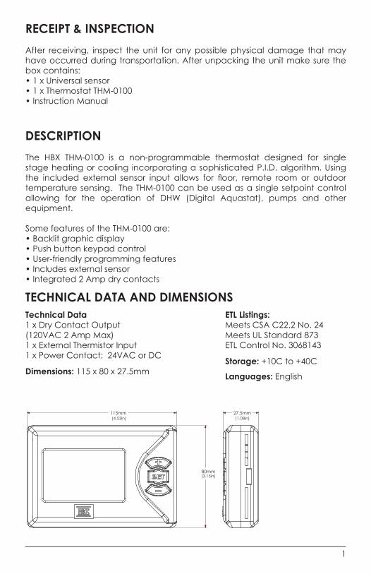
RECEIPT & INSPECTIONAfter receiving, inspect the unit for any possible physical damage that may have occurred during transportation. After unpacking the unit make sure the box contains:• 1 x Universal sensor• 1 x Thermostat THM-0100 • Instruction Manual
DESCRIPTION The HBX THM-0100 is a non-programmable thermostat designed for single stage heating or cooling incorporating a sophisticated P.I.D. algorithm. Using the included external sensor input allows for floor, remote room or outdoor temperature sensing. The THM-0100 can be used as a single setpoint control allowing for the operation of DHW (Digital Aquastat), pumps and other equipment.
Some features of the THM-0100 are:• Backlit graphic display• Push button keypad control• User-friendly programming features• Includes external sensor• Integrated 2 Amp dry contacts
Technical Data1 x Dry Contact Output (120VAC 2 Amp Max) 1 x External Thermistor Input 1 x Power Contact: 24VAC or DC
Dimensions: 115 x 80 x 27.5mm
ETL Listings: Meets CSA C22.2 No. 24 Meets UL Standard 873 ETL Control No. 3068143
Storage: +10C to +40C
Languages: English
115mm(4.53in) (1.08in)
(3.15in)80mm
27.5mm
TECHNICAL DATA AND DIMENSIONS
© 2014 HBX Controls2
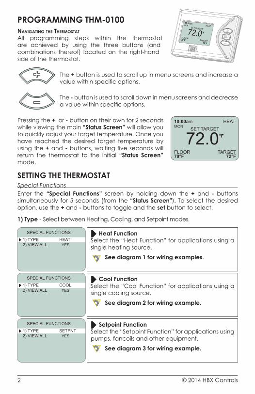
PROGRAMMING THM-0100navigating the thermostatAll programming steps within the thermostat are achieved by using the three buttons (and combinations thereof) located on the right-hand side of the thermostat.
The + button is used to scroll up in menu screens and increase a value within specific options.
The - button is used to scroll down in menu screens and decrease a value within specific options.
Pressing the + or - button on their own for 2 seconds while viewing the main “Status Screen” will allow you to quickly adjust your target temperature. Once you have reached the desired target temperature by using the + and - buttons, waiting five seconds will return the thermostat to the initial “Status Screen” mode.
SETTING THE THERMOSTATSpecial Functions Enter the “Special Functions” screen by holding down the + and - buttons simultaneously for 5 seconds (from the “Status Screen”). To select the desired option, use the + and - buttons to toggle and the set button to select.
1) Type - Select between Heating, Cooling, and Setpoint modes.
Heat FunctionSelect the “Heat Function” for applications using a single heating source.
See diagram 1 for wiring examples.
1) TYPE HEAT2) VIEW ALL YES
SPECIAL FUNCTIONS
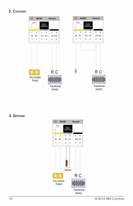
Cool FunctionSelect the “Cool Function” for applications using a single cooling source.
See diagram 2 for wiring example.
1) TYPE COOL2) VIEW ALL YES
SPECIAL FUNCTIONS
Setpoint FunctionSelect the “Setpoint Function” for applications using pumps, fancoils and other equipment.
See diagram 3 for wiring example.
1) TYPE SETPNT2) VIEW ALL YES
SPECIAL FUNCTIONS
72.0°F
10:00amMON SET TARGET
FLOOR79°F
TARGET72°F
HEAT
3
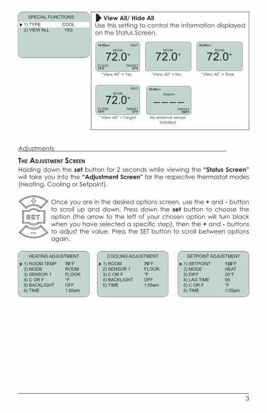
View All/ Hide AllUse this setting to control the information displayed on the Status Screen.
1) TYPE COOL2) VIEW ALL YES
SPECIAL FUNCTIONS
Adjustments
the aDjustment screenHolding down the set button for 2 seconds while viewing the “Status Screen” will take you into the “Adjustment Screen” for the respective thermostat modes (Heating, Cooling or Setpoint).
Once you are in the desired options screen, use the + and - button to scroll up and down. Press down the set button to choose the option (the arrow to the left of your chosen option will turn black when you have selected a specific step), then the + and - buttons to adjust the value. Press the SET button to scroll between options again.
72.0°FROOM
FLOOR79°F
TARGET72°F
HEAT
“View All” = Yes
72.0°F
10:00amROOM
“View All” = No“View All” = Yes “View All” = No “View All” = Time
“View All” = Target No external sensor installed
72.0°F
10:00amROOM
FLOOR79°F
TARGET72°F
HEAT
“View All” = Yes
72.0°FROOM
_ _ _ _10:00am
Setpoint
No external sensor installed
TARGET198°F
COOLING ADJUSTMENT
1) ROOM 70°F2) SENSOR 1 FLOOR3) C OR F °F4) BACKLIGHT OFF5) TIME 1:05am
HEATING ADJUSTMENT
1) ROOM TEMP 70°F2) MODE ROOM3) SENSOR 1 FLOOR4) C OR F °F5) BACKLIGHT OFF6) TIME 1:05am
SETPOINT ADJUSTMENT
1) SETPOINT 130°F2) MODE HEAT3) DIFF 20°F4) LAG TIME 0S5) C OR F °F6) TIME 1:05am
© 2014 HBX Controls4
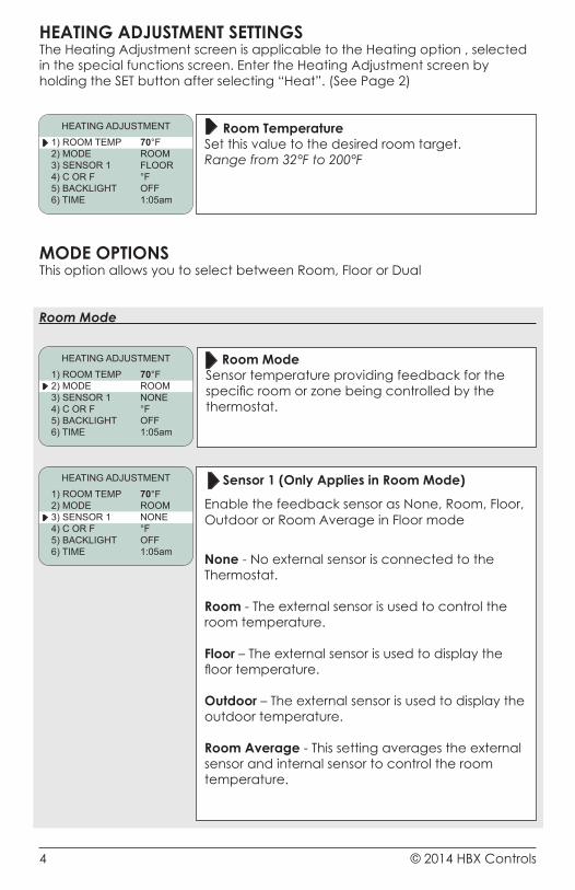
HEATING ADJUSTMENT SETTINGSThe Heating Adjustment screen is applicable to the Heating option , selected in the special functions screen. Enter the Heating Adjustment screen by holding the SET button after selecting “Heat”. (See Page 2)
Room TemperatureSet this value to the desired room target. Range from 32°F to 200°F
HEATING ADJUSTMENT
1) ROOM TEMP 70°F2) MODE ROOM3) SENSOR 1 FLOOR4) C OR F °F5) BACKLIGHT OFF6) TIME 1:05am
MODE OPTIONS This option allows you to select between Room, Floor or Dual
Room Mode
HEATING ADJUSTMENT
1) ROOM TEMP 70°F2) MODE ROOM3) SENSOR 1 NONE4) C OR F °F5) BACKLIGHT OFF6) TIME 1:05am
Room ModeSensor temperature providing feedback for the specific room or zone being controlled by the thermostat.
Sensor 1 (Only Applies in Room Mode)
Enable the feedback sensor as None, Room, Floor, Outdoor or Room Average in Floor mode
None - No external sensor is connected to the Thermostat.
Room - The external sensor is used to control the room temperature. Floor – The external sensor is used to display the floor temperature. Outdoor – The external sensor is used to display the outdoor temperature.
Room Average - This setting averages the external sensor and internal sensor to control the room temperature.
HEATING ADJUSTMENT
1) ROOM TEMP 70°F2) MODE ROOM3) SENSOR 1 NONE4) C OR F °F5) BACKLIGHT OFF6) TIME 1:05am
5
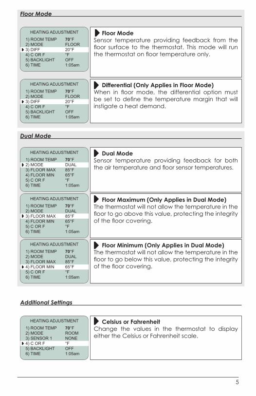
Floor Mode
Floor ModeSensor temperature providing feedback from the floor surface to the thermostat. This mode will run the thermostat on floor temperature only.
HEATING ADJUSTMENT
1) ROOM TEMP 70°F2) MODE FLOOR3) DIFF 20°F4) C OR F °F5) BACKLIGHT OFF6) TIME 1:05am
Differential (Only Applies in Floor Mode)When in floor mode, the differential option must be set to define the temperature margin that will instigate a heat demand.
HEATING ADJUSTMENT
1) ROOM TEMP 70°F2) MODE FLOOR3) DIFF 20°F4) C OR F °F5) BACKLIGHT OFF6) TIME 1:05am
Dual Mode
Dual ModeSensor temperature providing feedback for both the air temperature and floor sensor temperatures.
HEATING ADJUSTMENT
1) ROOM TEMP 70°F2) MODE DUAL3) FLOOR MAX 85°F4) FLOOR MIN 65°F5) C OR F °F6) TIME 1:05am
Floor Maximum (Only Applies in Dual Mode)The thermostat will not allow the temperature in the floor to go above this value, protecting the integrity of the floor covering.
HEATING ADJUSTMENT
1) ROOM TEMP 70°F2) MODE DUAL3) FLOOR MAX 85°F4) FLOOR MIN 65°F5) C OR F °F6) TIME 1:05am
Floor Minimum (Only Applies in Dual Mode)The thermostat will not allow the temperature in the floor to go below this value, protecting the integrity of the floor covering.
HEATING ADJUSTMENT
1) ROOM TEMP 70°F2) MODE DUAL3) FLOOR MAX 85°F4) FLOOR MIN 65°F5) C OR F °F6) TIME 1:05am
Additional Settings
Celsius or FahrenheitChange the values in the thermostat to display either the Celsius or Fahrenheit scale.
HEATING ADJUSTMENT
1) ROOM TEMP 70°F2) MODE ROOM3) SENSOR 1 NONE4) C OR F °F5) BACKLIGHT OFF6) TIME 1:05am
© 2014 HBX Controls6
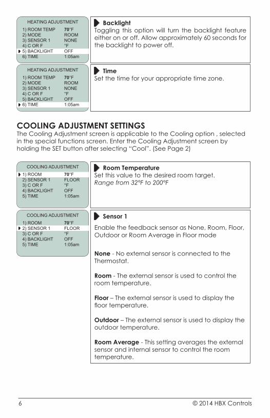
BacklightToggling this option will turn the backlight feature either on or off. Allow approximately 60 seconds for the backlight to power off.
HEATING ADJUSTMENT
1) ROOM TEMP 70°F2) MODE ROOM3) SENSOR 1 NONE4) C OR F °F5) BACKLIGHT OFF6) TIME 1:05am
TimeSet the time for your appropriate time zone.
HEATING ADJUSTMENT
1) ROOM TEMP 70°F2) MODE ROOM3) SENSOR 1 NONE4) C OR F °F5) BACKLIGHT OFF6) TIME 1:05am
COOLING ADJUSTMENT SETTINGSThe Cooling Adjustment screen is applicable to the Cooling option , selected in the special functions screen. Enter the Cooling Adjustment screen by holding the SET button after selecting “Cool”. (See Page 2)
Room TemperatureSet this value to the desired room target. Range from 32°F to 200°F
COOLING ADJUSTMENT
1) ROOM 70°F2) SENSOR 1 FLOOR3) C OR F °F4) BACKLIGHT OFF5) TIME 1:05am
Sensor 1
Enable the feedback sensor as None, Room, Floor, Outdoor or Room Average in Floor mode
None - No external sensor is connected to the Thermostat.
Room - The external sensor is used to control the room temperature. Floor – The external sensor is used to display the floor temperature. Outdoor – The external sensor is used to display the outdoor temperature.
Room Average - This setting averages the external sensor and internal sensor to control the room temperature.
COOLING ADJUSTMENT
1) ROOM 70°F2) SENSOR 1 FLOOR3) C OR F °F4) BACKLIGHT OFF5) TIME 1:05am
7
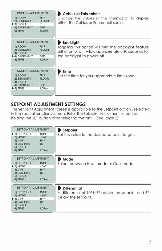
Celsius or FahrenheitChange the values in the thermostat to display either the Celsius or Fahrenheit scale.
COOLING ADJUSTMENT
1) ROOM 70°F2) SENSOR 1 FLOOR3) C OR F °F4) BACKLIGHT OFF5) TIME 1:05am
BacklightToggling this option will turn the backlight feature either on or off. Allow approximately 60 seconds for the backlight to power off.
COOLING ADJUSTMENT
1) ROOM 70°F2) SENSOR 1 FLOOR3) C OR F °F4) BACKLIGHT OFF5) TIME 1:05am
TimeSet the time for your appropriate time zone.
COOLING ADJUSTMENT
1) ROOM 70°F2) SENSOR 1 FLOOR3) C OR F °F4) BACKLIGHT OFF5) TIME 1:05am
SETPOINT ADJUSTMENT SETTINGSThe Setpoint Adjustment screen is applicable to the Setpoint option , selected in the special functions screen. Enter the Setpoint Adjustment screen by holding the SET button after selecting “Setpnt”. (See Page 2)
SetpointSet this value to the desired setpoint target.
SETPOINT ADJUSTMENT
1) SETPOINT 130°F2) MODE HEAT3) DIFF 20°F4) LAG TIME 0S5) C OR F °F6) TIME 1:05am
ModeSelect between Heat mode or Cool mode.
SETPOINT ADJUSTMENT
1) SETPOINT 130°F2) MODE HEAT3) DIFF 20°F4) LAG TIME 0S5) C OR F °F6) TIME 1:05am
DifferentialA differential of 10° is 5° above the setpoint and 5° below the setpoint.
SETPOINT ADJUSTMENT
1) SETPOINT 130°F2) MODE HEAT3) DIFF 20°F4) LAG TIME 0S5) C OR F °F6) TIME 1:05am
© 2014 HBX Controls8
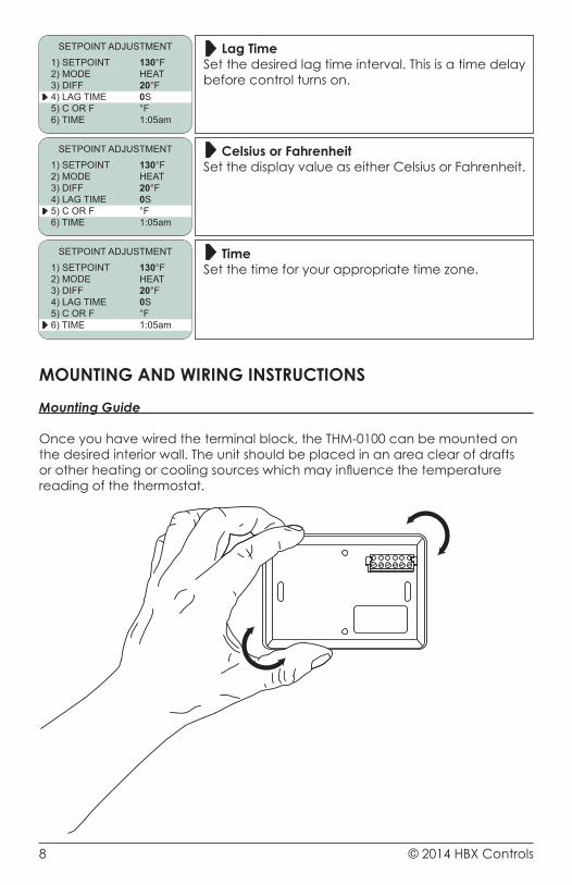
Lag TimeSet the desired lag time interval. This is a time delay before control turns on.
SETPOINT ADJUSTMENT
1) SETPOINT 130°F2) MODE HEAT3) DIFF 20°F4) LAG TIME 0S5) C OR F °F6) TIME 1:05am
Celsius or FahrenheitSet the display value as either Celsius or Fahrenheit.
SETPOINT ADJUSTMENT
1) SETPOINT 130°F2) MODE HEAT3) DIFF 20°F4) LAG TIME 0S5) C OR F °F6) TIME 1:05am
TimeSet the time for your appropriate time zone.
SETPOINT ADJUSTMENT
1) SETPOINT 130°F2) MODE HEAT3) DIFF 20°F4) LAG TIME 0S5) C OR F °F6) TIME 1:05am
MOUNTING AND WIRING INSTRUCTIONS
Mounting Guide
Once you have wired the terminal block, the THM-0100 can be mounted on the desired interior wall. The unit should be placed in an area clear of drafts or other heating or cooling sources which may influence the temperature reading of the thermostat.
9
1 2 3 4 5 6
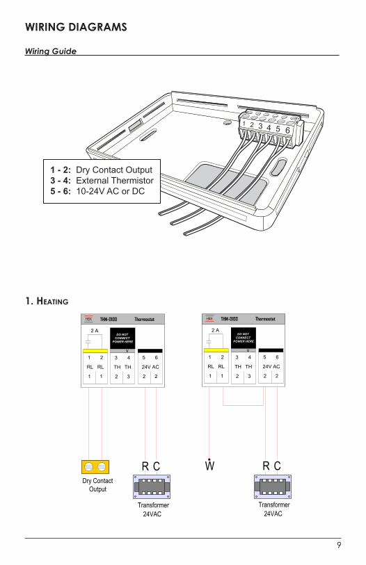
1 - 2: Dry Contact Output3 - 4: External Thermistor5 - 6: 10-24V AC or DC
WIRING DIAGRAMS
Wiring Guide
1. heating
1) Heating
THM-0100HBX
2
24V AC
65
2
TH
2
TH
43
3
Thermostat
RL
1
RL
21
1
2 ADO NOT
CONNECT POWER HERE
v
W R C
Transformer24VAC
THM-0100HBX
2
24V AC
65
2
TH
2
TH
43
3
Thermostat
RL
1
RL
21
1
2 ADO NOT
CONNECT POWER HERE
v
R C
Transformer24VAC
Dry Contact Output
© 2014 HBX Controls10
3. setPoint
R C
Transformer24VAC
Dry Contact Output
Sensor
THM-0100HBX
2
24V AC
65
2
TH
2
TH
43
3
Thermostat
RL
1
RL
21
1
2 ADO NOT
CONNECT POWER HERE
v
3) Setpoint
2. cooling
THM-0100HBX
2
24V AC
65
2
TH
2
TH
43
3
Thermostat
RL
1
RL
21
1
2 ADO NOT
CONNECT POWER HERE
v
Y R C
Transformer24VAC
2) Cooling
THM-0100HBX
2
24V AC
65
2
TH
2
TH
43
3
Thermostat
RL
1
RL
21
1
2 ADO NOT
CONNECT POWER HERE
v
R C
Transformer24VAC
Dry Contact Output

11
NOTES:

© 2014 HBX Controls12
NOTES:

13
LIMITED WARRANTYHBX Controls warrants each of its products to be free from defects in workmanship and materials under normal use and service for a period of 24 months from date of manufacture or 12 months from date of purchase from an HBX Authorized Dealer, if within the above documented period after date of manufacture.
If the product proves to be defective within the applicable warranty period, HBX on its sole discretion will repair or replace said product. Replacement product may be new or refurbished of equivalent or better specifications, relative to the defective product. Replacement product need not be of identical design or model. Any repair or replacement product pursuant to this warranty shall be warranted for not less than 90 days from date of such repair, irrespective of any earlier expiration of original warranty period. When HBX provides replacement, the defective product becomes the property of HBX Controls.
Warranty Service, within the applicable warranty period, may be obtained by contacting your nearest HBX Controls office via the original Authorized Agent and requesting a Return Material Authorization Number (RMA #). Proof of purchase in the form a dated invoice/receipt must be provided to expedite the issuance of a Factory RMA.
After an RMA number has been issued, the defective product must be packaged securely in the original or other suitable shipping package to ensure that it will not be damaged in transit. The RMA number must be visible on the outside of the package and a copy included inside the package. The package must be mailed or otherwise shipped back to HBX with all costs of mailing/shipping/insurance prepaid by the warranty claimant.
Any package/s returned to HBX without an approved and visible RMA number will be rejected and shipped back to purchaser at purchaser’s expense. HBX reserves the right, if deemed necessary, to charge a reasonable levy for costs incurred, additional to mailing or shipping costs.
limitation of warrantiesIf the HBX product does not operate as warranted above the purchasers sole remedy shall be, at HBX’s option, repair or replacement. The foregoing warranties and remedies are exclusive and in lieu of all other warranties, expressed or implied, either in fact or by operation of law, statutory or otherwise, including warranties of merchantability and fitness for a particular purpose/application. HBX neither assumes nor authorizes any other person to assume for it any other liability in connection with the sale, installation maintenance or use of HBX Controls products.
HBX shall not be liable under this warranty; if its testing and examination discloses that the alleged defect in the product does not exist or was caused by the purchasers or third persons misuse, neglect, improper installation or testing, unauthorized attempts to repair or any other cause beyond the range of intended use, or by accident, fire, lightning or other hazard.
limitation of liabilityIn no event will HBX be liable for any damages, including loss of data, loss of profits, costs of cover or other incidental, consequential or indirect damages arising out of the installation, maintenance, commissioning, performance, failure or interruption of an HBX product, however caused and on any theory of liability. This limitation will apply even if HBX has been advised of the possibility of such damage.
local lawThis limited warranty statement gives the purchaser specific legal rights. The purchaser may also have other rights which vary from state to state in the United States, from Province to Province in Canada and from Country to Country elsewhere in the world.
To the extent this Limited Warranty Statement is inconsistent with local law, this statement shall be deemed modified to be consistent with such local law. Under such local law, certain disclaimers and limitations of this statement may not apply to the purchaser. For example, some states in the United States, as well as some governments outside the United States (including Canadian Provinces), may: Preclude the disclaimers and limitations in this statement from limiting the statutory rights of a consumer (e.g. United Kingdom);
Otherwise restrict the ability of a manufacturer to enforce such disclaimers or limitations; or grant the purchaser additional warranty rights which the manufacturer cannot disclaim, or not allow limitations on the duration of implied warranties.

V1.02
© HBX Control Systems Inc. 2012
HBX Control Systems Inc.4516 - 112th Avenue SECalgary, AB Canada T2C 2K2


![EGR1 Plays Synthesis of HBx(+) Hepatocytesdownloads.hindawi.com/journals/mi/2015/372750.pdf · HBx) [ ], HepG cells (a human hepatocarcinomal cell line, HB- , ATCC, VA), and HepG-HBx](https://static.fdocuments.in/doc/165x107/5f57c5b0381d5a575c0d116d/egr1-plays-synthesis-of-hbx-hbx-hepg-cells-a-human-hepatocarcinomal-cell.jpg)