VERSATILE, MODULAR, TIME SAVING SYSTEM.nationalforming.com/assets/nfs_a_frame_fly_forms.pdfThe...
16
A-FRAME FLY FORMS VERSATILE, MODULAR, TIME SAVING SYSTEM.
Transcript of VERSATILE, MODULAR, TIME SAVING SYSTEM.nationalforming.com/assets/nfs_a_frame_fly_forms.pdfThe...

A-FRAME FLY FORMSVERSATILE, MODULAR, TIME SAVING SYSTEM.
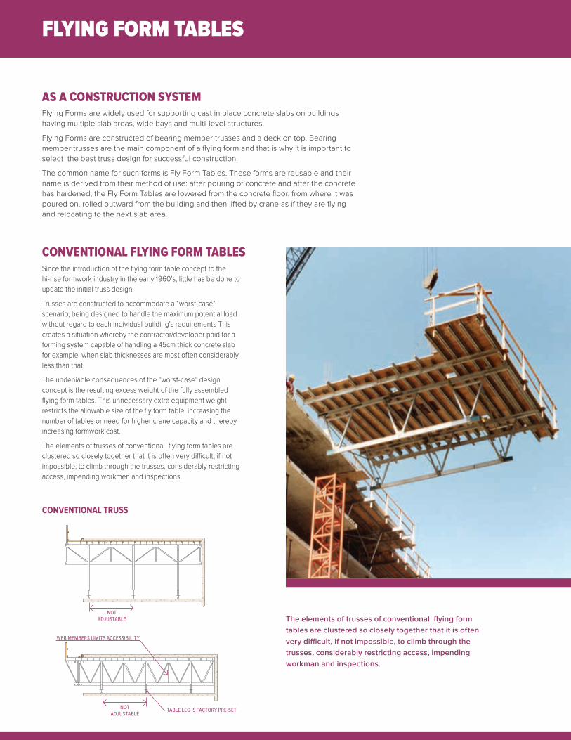
Flying Forms are widely used for supporting cast in place concrete slabs on buildings having multiple slab areas, wide bays and multi-level structures.
Flying Forms are constructed of bearing member trusses and a deck on top. Bearing member trusses are the main component of a flying form and that is why it is important to select the best truss design for successful construction.
The common name for such forms is Fly Form Tables. These forms are reusable and their name is derived from their method of use: after pouring of concrete and after the concrete has hardened, the Fly Form Tables are lowered from the concrete floor, from where it was poured on, rolled outward from the building and then lifted by crane as if they are flying and relocating to the next slab area.
FLYING FORM TABLES
CONVENTIONAL FLYING FORM TABLES
AS A CONSTRUCTION SYSTEM
Since the introduction of the flying form table concept to the hi-rise formwork industry in the early 1960’s, little has be done to update the initial truss design.
Trusses are constructed to accommodate a “worst-case” scenario, being designed to handle the maximum potential load without regard to each individual building’s requirements This creates a situation whereby the contractor/developer paid for a forming system capable of handling a 45cm thick concrete slab for example, when slab thicknesses are most often considerably less than that.
The undeniable consequences of the “worst-case” design concept is the resulting excess weight of the fully assembled flying form tables. This unnecessary extra equipment weight restricts the allowable size of the fly form table, increasing the number of tables or need for higher crane capacity and thereby increasing formwork cost.
The elements of trusses of conventional flying form tables are clustered so closely together that it is often very difficult, if not impossible, to climb through the trusses, considerably restricting access, impending workmen and inspections.
The elements of trusses of conventional flying form tables are clustered so closely together that it is often very difficult, if not impossible, to climb through the trusses, considerably restricting access, impending workman and inspections.
NOT ADJUSTABLE
NOT ADJUSTABLE
WEB MEMBERS LIMITS ACCESSIBILITY
TABLE LEG IS FACTORY PRE-SET
CONVENTIONAL TRUSS
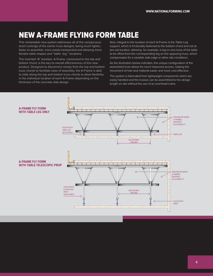
NEW A-FRAME FLYING FORM TABLEThis remarkable new system addresses all of the conspicuous short-comings of the earlier truss designs, being much lighter, faster to assemble, more easily transported and allowing more flexible table shapes and “table -leg “ locations.
The inverted “A” member, A-Frame, connected to the top and bottom chord, is the key to overall effectiveness of this new product. Designed to disconnect simply from the top and bottom truss chords to facilitate ease of assembly, the A-Frame is able to slide along the top and bottom truss chords to allow flexibility in the individual location of each A-Frame depending on the thickness of the concrete slab design.
Also, integral to the location of each A-Frame is the Table Leg support, which is frictionally fastened to the bottom chord and not at pre-set location, allowing for example, a leg on one truss of the table to be offset from the corresponding leg on the opposing truss, which compensates for a variable slab edge or other site conditions.
As the illustration below indicates, the unique configuration of the assembled truss allows for much improved access, making the movement of man and material easier and more cost effective.
The system is fabricated from lightweight components which are easily handled and the trusses can be assembled to the design length on site without the use of an overhead crane.
A-FRAME FLY FORM WITH TABLE LEG ONLY
A-FRAME FLY FORM WITH TABLE TELESCOPIC PROP
SPACING BETWEEN A-FRAMES PROVIDES ACCESSIBILITY
TABLE LEG
TELESCOPIC PROP
SPACING BETWEEN A-FRAMES PROVIDES ACCESSIBILITY
POSITION OF TABLE LEG ADJUSTABLE
POSITION OF EXTENTION PROP ADJUSTABLE
ADJUSTABLE SPACING
ADJUSTABLE SPACING
4
WWW.NATIONALFORMING.COM

A-FRAME FLY FORM TABLE SYSTEM
ECONOMICAL AND TIME SAVING SYSTEM
TYPICAL TABLE RELOCATON FLYING CYCLE
1. Fly Form Table supports cast in place concrete slab
2. When concrete reaches required strength, Fly Form Table is lowered and rolled outward from building
3. Fly Form Table is then lifted by crane and flown up from underneath of concrete slab
4. Fly Form Table is placed on top of previously poured slab.
The A-Frame Fly Form System meets the demands of today’s challenging environments that require a flexible and time saving construction system. The A-Frame Fly Form System is fully adaptable to the design and shoring height of a concrete slab.
Configuration of A-Frame trusses and shape of A-Frame Fly Form Tables are built for each individual project, to maximize formwork demands resulting in considerable savings in time and labor to formwork contractors.
Due to the spacing between the A-Frames, access underneath and between the tables is significantly improved. This allows for more cost effective movement of man and material, as well as more thorough inspection of elevations and general conditions of the forms.
With table sizes to date of 350 M2 (3,760 sq. ft.), this new A-Frame Flying Form System has been pivotal to the success of several Las Vegas mega hotels, completed on 4 day and even 3 day cycles, due to the reduced number of tables to fly and the attending saving in labor. Naturally this results in a faster, less costly concrete construction process and an improved profit picture.
1
2
3
4
1
2
3
4

A-FRAME FLY FORM TABLE COMPONENTS
A-FRAME TRUSS COMPONENTS
Pair of parallel A-Frame Trusses
Telescopic Props
Hinged Table Leg
Cross Braces to keep distance between A-Frame Trusses
Forming Deck Surface over Trusses.
Top Truss Chord, H-750 aluminum beam
A-Frame, Truss web member
Bottom Truss Chord, H-750 aluminum beam
Telescopic Prop with Table Leg
1
2
3
4
1
2
3
4
5
12
34
5
1
4
2
3
6
WWW.NATIONALFORMING.COM

WITH TELESCOPIC PROP AND HINGED TABLE LEGOn buildings where the ceiling height exceeds 2.7M (9’-0”) Telescopic Props are required to elevate A-Frame Trusses to the necessary height of up to 4.05M (13’-3”).
Installation and dismantling is very simple and efficient as Telescopic Props are mounted on the side of A-Frames.
Telescopic Props with Table Legs A or Table Legs B are the best solution, especially if the floor to ceiling height varies during construction.
SHORING HEIGHT FROM 2.7m TO 4.05m
A-FRAME TRUSS ADAPTABILITY TO SHORING HEIGHTS
Telescopic prop with table leg in position for support of fly form table
Retracted telescopic prop with hinged table leg in position for relocation of fly form
21
1
2

On buildings where the ceiling height is less then 2.75M (9’-0”) use of Table Legs only, attached to the bottom truss chord, is the most efficient fly form table system, as it saves labour, time for relocation and set-up of tables for subsequent concrete pours.
Two types of Table Legs are available: Table Leg A and Table Leg B and both use the same friction hinge device for attachment to the bottom truss chord. They can be attached at any location along the bottom truss chord. Table Legs can be simply and efficiently interchanged during construction to accommodate different floor to floor heights.
WITH HINGED TABLE LEGS ONLY
Table Leg in position for support of fly form table.
Hinged Table Leg in position for relocation of fly form table.
Position of Table Leg beneath the bottom truss chord is adjustable to accommodate any variation in the configuration of the slab edge.
SHORING HEIGHT FROM 2.4m TO 3.00m
TABLE LEG BTABLE LEG A
3
4
600 mm
305 mm
TABLE LEG
A-FRAME TRUSS
A-FRAME TRUSS
SLAB
ED
GE
4
3
8
WWW.NATIONALFORMING.COM

A-FRAME FLY FORMS ADVATAGES
OPTIMUM TRUSS CONFIGURATIONThe unique feature of the A-Frame Truss System is its capability to utilize the optimum weight of trusses in relation to project specific concrete structure mass. This feature is accomplished by having the option of positioning truss web members, A-Frames, at any location between top and bottom truss chords.
Based on the maximum capacity of each Telescopic Prop and Table Leg of 8.3 ton (18,300 Lb) attached to A-Frames and with the option to vary the spacing between A-Frames, it is possible to achieve optimum ratio between truss weight and truss capacity for a project.
For heavy concrete structures, in order to have maximum utilization of truss capacity, spacing between A-Frames decreases while the weight of trusses increases.
For light concrete structures, in order to have maximum utilization of truss capacity, spacing between A-Frames increases, while the weight of the truss decreases and therefore forming equipment becomes more economical.
With multiple A-Frame truss configurations, using two, three or four rows of trusses, A-Frame Fly Form Tables can be used for slab shoring heights up to 8.00 M (26’-3”)
MULTIPLE TRUSS CONFIGURATION
TABLE LEG 8.3T MAX CAPACITY
TABLE LEG 8.3T MAX CAPACITY
TRUSS CONFIGURATION FOR HEAVY STRUCTURES
TRUSS CONFIGURATION FOR LIGHT STRUCTURES
Multiple a-frame truss configuration
1

SECONDARY TRUSS CHORD
PARAPET WALL
TRUSS SUPPORT FOR WORKING PLATFORM
In order to use A-Frame Fly Forms for slab shoring heights of 4.65M (15’-3”), the Secondary Truss Chord is introduced.
The Extension Column 60cm (24”) high is bolted on top of the truss and horizontally braced in order to support a secondary truss chord.
With the use of A-Frame 120 for truss assembly, a minimum clearance height of 1.80M (6’-0”) is required for relocation of the table. This compact A-Frame Truss allows pouring of parapet or upstanding walls at the same time as a suspended slab. High rollers are used for sliding the forms out from the underside of the slab.
With positioning of A-Frames next to each other, and placing A-Frame Trusses on two supports only at each end, A-Frame Trusses can be used as “bridge” members for support of man working platforms. Span and number of trusses spaced apart depends on loading requirements of a project. Maximum span of 30.5M (100’-0”) with trusses spaced at 0.9M (3’-0”) provide 245KG/M2 (50Lb/sf) of loading capability.
TELESCOPIC EXTENTION LEG
EXTENTION COLUMN
SECONDARY TRUSS CHORD
4.65M
HINGED TABLE LEG B TABLE LEG
2400mm (8’-0”)
1220mm (6’-0”)
A-FORM 1220mm HIGH
1800 mm (6’-0”)
WORKING PLATFORM 245KG/M2
12
WWW.NATIONALFORMING.COM

REFERENCE PROJECTS
HOTEL MANDALAY BAY LAS VEGAS, NEVADA
SHAW TOWER VANCOUVER, B.C.
HOKUA BUILDING HONOLULU, HAWAII
RESIDENTIAL TOWER VANCOUVER, B.C.

SHERATON WALL HOTEL VANCOUVER, B.C.
CALLISTO - COAL HARBOUR VANCOUVER, B.C.
THE ERICKSON VANCOUVER, B.C.
HOTEL MONTE CARLO LAS VEGAS, NEVADA
14
WWW.NATIONALFORMING.COM
A-FRAME FLY FORM TRUSS VERSABILITY
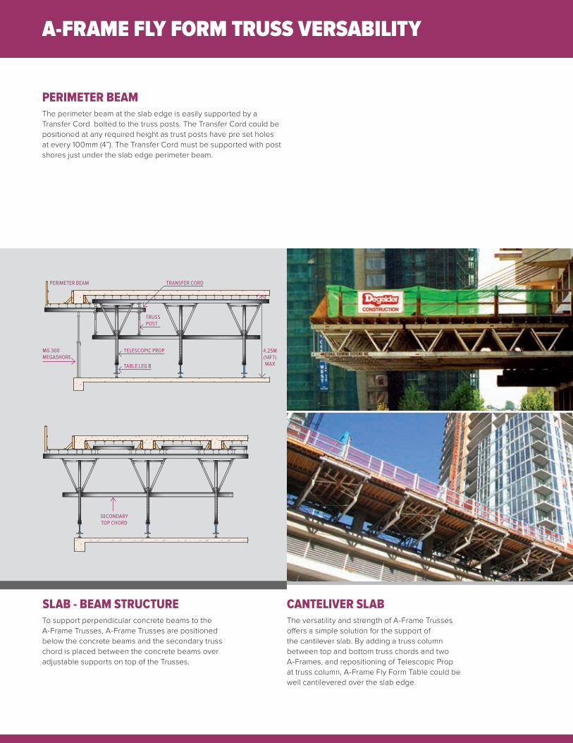
PERIMETER BEAM
CANTELIVER SLABSLAB - BEAM STRUCTURE
The perimeter beam at the slab edge is easily supported by a Transfer Cord bolted to the truss posts. The Transfer Cord could be positioned at any required height as trust posts have pre set holes at every 100mm (4”). The Transfer Cord must be supported with post shores just under the slab edge perimeter beam.
The versatility and strength of A-Frame Trusses offers a simple solution for the support of the cantilever slab. By adding a truss column between top and bottom truss chords and two A-Frames, and repositioning of Telescopic Prop at truss column, A-Frame Fly Form Table could be well cantilevered over the slab edge.
To support perpendicular concrete beams to the A-Frame Trusses, A-Frame Trusses are positioned below the concrete beams and the secondary truss chord is placed between the concrete beams over adjustable supports on top of the Trusses.
PERIMETER BEAM TRANSFER CORD
TRUSS POST
TELESCOPIC PROPMG 300 MEGASHORE
TABLE LEG B
4.25M (14FT) MAX
SECONDARY TOP CHORD

A-FRAME FLY FORMS ADVATAGES
VARIABLE TRUSS LENGTHWith modular lengths of Top and Bottom Truss Chord, ability to join them together and to position A-Frames with Telescopic Props and Table Legs at any location between them, A-Frame Truss lengths could be designed to accommodate any truss length requirement of a project. Maximum truss length is determine by project conditions and available crane capacity of a project. A-Frame Truss length is adjustable in increments of 1.5 M (5 feet).
TRANSPORTATION AND STORAGE
PRODUCTION AND FORM ASSEMBLEY
The various members of A-Frame Trusses are easily and compactly packaged for shipment and storage. Truss members required to assemble A-Frame trusses for 1,000 M2 of suspended slab can be conveniently loaded on a 12.00M long truck deck for shipping or storage,
National Forming Systems Inc. is proud to manufacture its products at its own production facilities, retaining full process and quality control. Robotic welding and mass production of units ensures a large inventory available to promptly respond to customers’ needs at an affordable cost.
With a full service assembly facility, National Forming Systems Inc. can assemble custom made A-Frame Trusses for a project, load the assembled trusses on trailer trucks and deliver to the job site. Such assembled A-Frame Trusses can be used to form A-Frame Fly Form Tables right away. The cost of preassembled A-Frame Trusses by National Forming Systems Inc. is 1/3 of assembly cost of the same trusses by forming contractor on site.
7.62M (25ft)6.10M (20ft)
4.57M (15ft) 1.5M 1.5M 1.5M
Up to 30,000m (100ft)
16
WWW.NATIONALFORMING.COM

TABLE RELOCATION OPTIONS
ELECTRIC HOIST - TURFER
PINCHING METHOD
The Electric Hoist is a device attached to the crane hook, consisting of two chains supporting back lifting points of a table. When a table is rolled out, the two chains from the crane hook support two table front lifting points while two chains from Electric Hoist support table back lifting points. With use of a remote controlled Electric Hoist, it pulls the back-side of a table until the table reaches a level position and is ready for relocation.
This is a safe relocation method but requires tables to be pushed out in order to be picked-up by the crane and the rigger to connect lifting chains at four table lifting points.
The Pinching Method got its name from the table position when it is pinched between slab and ceiling in order to be picked-up by the crane.
It is a fast and labour intense relocation method that requires high skills and experience of workers. It also requires engineering approval of the truss bottom chord capacity as this relocation method creates a high point load on the bottom truss chord.
A-FRAME TRUSS DATAA-FRAME TRUSS CAPACITY
BOTTOM CHORD CAPACITY
4200400038003600340032003000280026002400220020001800
6 6.5 7 7.5 8 8.5 9 9.5 10 FTSPACING BETWEEN TABLE LEGS ONLY SPACING BETWEEN TELESCOPIC PROPS WITH TABLE LEGS
LIN
EAR
LOAD
Lb/
Lf
300002750025000225002000017500150001250010000750050002500
6 6.5 7 7.5 8 8.5 9 9.5 10 FT
POIN
T LO
AD L
b
SPACING BETWEEN APEXES OF A-FRAMES
SPACING
SPACING BETWEEN APAXES OF A-FRAMES
POINT LOAD

SKY LIFT
A-FLY FORMS ACCESORIES
The Sky Lift is a U- shaped lifting gravity device supported by a crane, consisting of an upper horizontal arm with a trolley for leveling purposes and a lower horizontal arm for lifting tables. Before a table is lifted, the trolley, with remote control, is placed in a position so that the table is leveled when lifting and relocating.
Relocation of tables with the Sky Lift is the most safest and least laboru intense relocation method. It eliminates the need to roll out tables in order to be picked-up by the crane and also eliminates the rigger need to attach crane chains to four lifting table points.
SKY LIFT CAPACITY
Maximum Table Length is 12.20m (40ft) Maximum Table Weight is 2.7t (6,000lb)
Hydraulic Jack
Gliding Roller
Lifting Bracket
Caster
Floor Jack up to 30”
Railing Bracket
1
2
3
4
5
6
6 5
1
4
3
2
10
WWW.NATIONALFORMING.COM

North America Locations
Head Office - Vancouver 7411 Vantage Way Delta, BC Canada V4G 1C9 Tel: +1 604 946 0090 Fax: +1 604 946 6830
Kelowna 310 Carion Road Kelowna, BC Canada V4V 2K5 Tel: +1 250 766 9315 Fax: +1 250 766 9317
Toronto 9-334 Queen St South Suite 420 Bolton, ON Canada L7E 2N9 Tel: +1 480 305 1854 Fax: +1 480 305 1855
International Locations
Slovenia Zirovnica 107/A 4274 Slovenia, Zirovnica Tel: +386 5 99 34 014 Fax: +386 4 58 41 994
Serbia Milovana Marinkovica 33 11040 Belgrade Republic of Serbia Tel: +381 11 31 92 322 Fax: +381 11 39 80 335
California 23325 Cajalco Road Perris, CA USA 92570 Tel: +1 951 943 4838 Fax: +1 951 943 4637
Nevada 3321 N Buffalo Drive Las Vegas, NV USA 89129 Tel: +1 951 943 4838 Fax: +1 951 943 4637
Hawaii 348 Puuhale Road Honolulu, HI USA 96819 Tel: +1 808 841 1111 Fax: +1 808 841 6400
Branch Offices
Dubai, UAE Hong Kong, China Doha, Qatar Taipei, Taiwan R.O.C.
VANCOUVER, BC HOMETOWN OF NATIONAL FORMING SYSTEMS INC