VersaFlow Ultrasonic clamp-on Flowmeter Specificationseneric.net/Honeywell/Technical-data/VersaFlow...
15
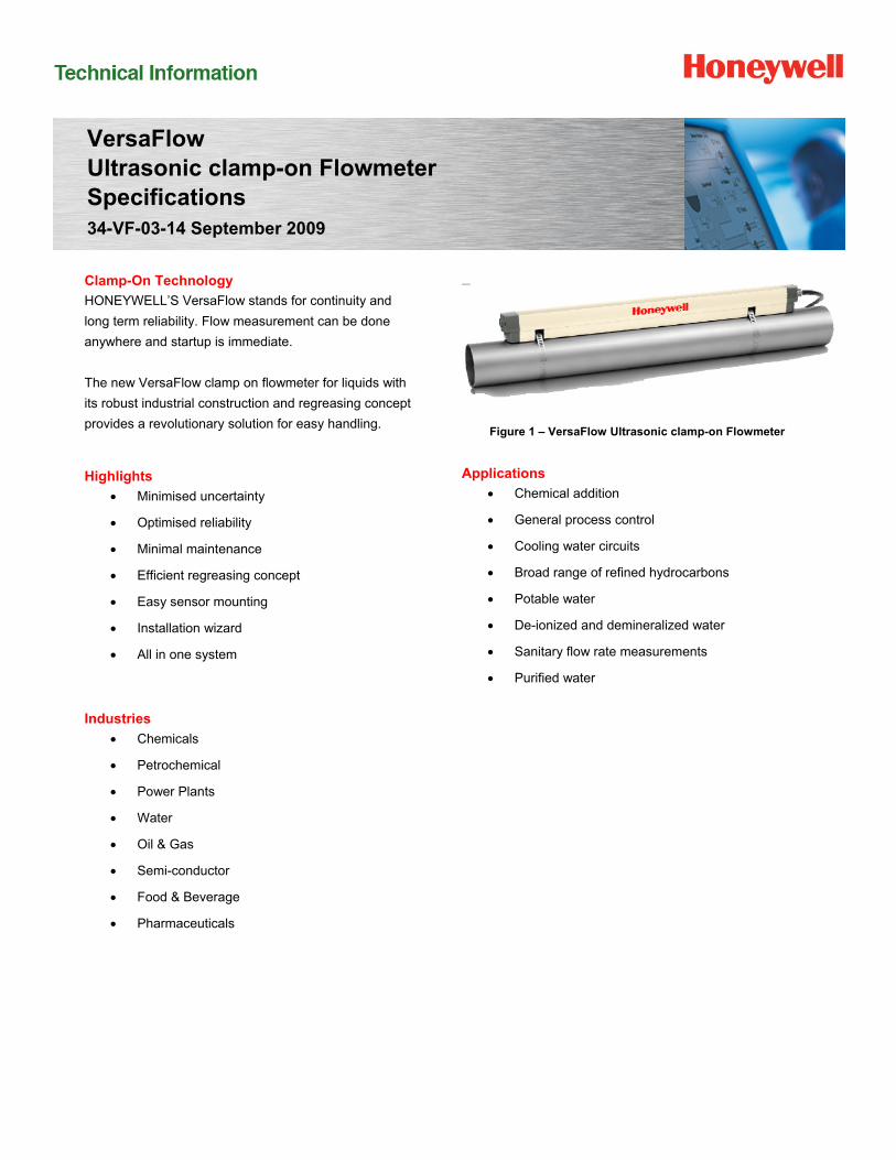
VersaFlow Ultrasonic clamp-on Flowmeter Specifications 34-VF-03-14 September 2009 Clamp-On Technology HONEYWELL’S VersaFlow stands for continuity and long term reliability. Flow measurement can be done anywhere and startup is immediate. The new VersaFlow clamp on flowmeter for liquids with its robust industrial construction and regreasing concept provides a revolutionary solution for easy handling. Highlights Minimised uncertainty Optimised reliability Minimal maintenance Efficient regreasing concept Easy sensor mounting Installation wizard All in one system Industries Chemicals Petrochemical Power Plants Water Oil & Gas Semi-conductor Food & Beverage Pharmaceuticals Figure 1 – VersaFlow Ultrasonic clamp-on Flowmeter Applications Chemical addition General process control Cooling water circuits Broad range of refined hydrocarbons Potable water De-ionized and demineralized water Sanitary flow rate measurements Purified water
Transcript of VersaFlow Ultrasonic clamp-on Flowmeter Specificationseneric.net/Honeywell/Technical-data/VersaFlow...
VersaFlow Ultrasonic clamp-on Flowmeter Specifications 34-VF-03-14 September 2009
Clamp-On Technology
HONEYWELL’S VersaFlow stands for continuity and
long term reliability. Flow measurement can be done
anywhere and startup is immediate.
The new VersaFlow clamp on flowmeter for liquids with
its robust industrial construction and regreasing concept
provides a revolutionary solution for easy handling.
Highlights
Minimised uncertainty
Optimised reliability
Minimal maintenance
Efficient regreasing concept
Easy sensor mounting
Installation wizard
All in one system
Industries
Chemicals
Petrochemical
Power Plants
Water
Oil & Gas
Semi-conductor
Food & Beverage
Pharmaceuticals
Figure 1 – VersaFlow Ultrasonic clamp-on Flowmeter
Applications
Chemical addition
General process control
Cooling water circuits
Broad range of refined hydrocarbons
Potable water
De-ionized and demineralized water
Sanitary flow rate measurements
Purified water
HFS Catalog_Without Tab_HighRes.pdf 1031 6/8/2011 12:41:48 PM
VersaFlow Ultrasonic clamp-on Flowmeter 2
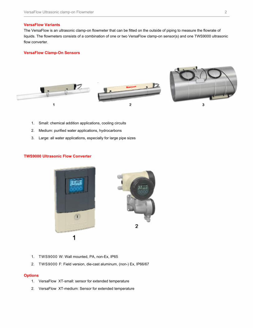
VersaFlow Variants
The VersaFlow is an ultrasonic clamp-on flowmeter that can be fitted on the outside of piping to measure the flowrate of
liquids. The flowmeters consists of a combination of one or two VersaFlow clamp-on sensor(s) and one TWS9000 ultrasonic
flow converter.
VersaFlow Clamp-On Sensors
1. Small: chemical addition applications, cooling circuits
2. Medium: purified water applications, hydrocarbons
3. Large: all water applications, especially for large pipe sizes
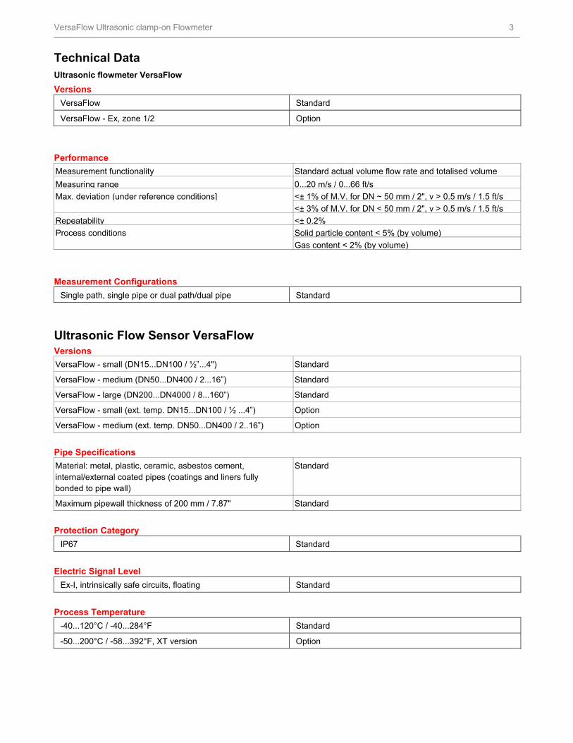
TWS9000 Ultrasonic Flow Converter
1. TWS9000 W: Wall mounted, PA, non-Ex, IP65
2. TWS9000 F: Field version, die-cast aluminum, (non-) Ex, IP66/67
Options
1. VersaFlow XT-small: sensor for extended temperature
2. VersaFlow XT-medium: Sensor for extended temperature
HFS Catalog_Without Tab_HighRes.pdf 1032 6/8/2011 12:41:48 PM
VersaFlow Ultrasonic clamp-on Flowmeter 3
Technical Data Ultrasonic flowmeter VersaFlow
Versions
VersaFlow Standard
VersaFlow - Ex, zone 1/2 Option
Performance
Measurement functionality Standard actual volume flow rate and totalised volume
Measuring range 0...20 m/s / 0...66 ft/s
Max. deviation (under reference conditions] <± 1% of M.V. for DN ~ 50 mm / 2", v > 0.5 m/s / 1.5 ft/s
<± 3% of M.V. for DN < 50 mm / 2", v > 0.5 m/s / 1.5 ft/s
Repeatability <± 0.2%
Process conditions Solid particle content < 5% (by volume) Gas content < 2% (by volume)
Measurement Configurations
Single path, single pipe or dual path/dual pipe Standard
Ultrasonic Flow Sensor VersaFlow Versions
VersaFlow - small (DN15...DN100 / ½”...4") Standard
VersaFlow - medium (DN50...DN400 / 2...16”) Standard
VersaFlow - large (DN200...DN4000 / 8...160”) Standard
VersaFlow - small (ext. temp. DN15...DN100 / ½ ...4”) Option
VersaFlow - medium (ext. temp. DN50...DN400 / 2..16”) Option
Pipe Specifications
Material: metal, plastic, ceramic, asbestos cement, internal/external coated pipes (coatings and liners fully bonded to pipe wall)
Standard
Maximum pipewall thickness of 200 mm / 7.87" Standard
Protection Category
IP67 Standard
Electric Signal Level
Ex-I, intrinsically safe circuits, floating Standard
Process Temperature
-40...120°C / -40...284°F Standard
-50...200°C / -58...392°F, XT version Option
HFS Catalog_Without Tab_HighRes.pdf 1033 6/8/2011 12:41:48 PM
VersaFlow Ultrasonic clamp-on Flowmeter 4
Sensor Cable Length
5 m / 15 t Standard
10 m / 30ft Option
20 m / 0ft Option
30 m / 90ft Option
Recommended Mounting Areas
Inlet ~ 10DN
Outlet ~ 5DN
Ultrasonic Flow Converter TWS9000 Versions
W (wall) TWS9000 W (general purpose)
F (field) TWS9000 F (non-Ex)
F(/i-)Eex, zone 1/2 TWS9000 F-Ex
Display Languages
With Local display Standard
English, French, German Standard
Flow Sensor
VersaFlow DN15...4000 / ½”...1601
Communication
Current, pulse & status output Standard
HART® communication, control input Standard
Power Supply
100...230 VAC (-15/+10%), 50/60 Hz Standard
24 VAC/DC Option
Power consumption 22 VA
Approvals
EEx - zone 1, zone 2 Option
FM - Class I DIV 1, DIV 2 Option
CSA - / Class I DIV 1, DIV 2 Option
Protection Category
W (wall) IP65 (eq. to NEMA 4/4X)
F (field) IP66/67 (eq. to NEMA6)
Temperature
Process see flow sensor
Ambient -40....60°C / -40....140°F
Storage -50....70°C / -58....158°F
Cable Connection
M20 x 1.5 Standard
½” NPT Option
PF ½” Option 1 Outer Diameter: 20…4300 mm / 0.79…169.29”
HFS Catalog_Without Tab_HighRes.pdf 1034 6/8/2011 12:41:48 PM
VersaFlow Ultrasonic clamp-on Flowmeter 5
Materials Used
Polyamide - polycarbonate (W-version) Standard
Die-cast aluminium with polyurethane coating) (F-version) Standard
Stainless steel 316 L / 1.4404 (F-version) Option
Overall Functionality
Highlights Continuous measurement of actual volume flow rate, flow velocity, velocity of sound, damping of acoustic signal, signal to noise ratio
Flow direction (forward or reverse) Totalisation of volume flow
Reliability of flow measurement, Quality of acoustic signal
Current Output
Function All operating data configurable; galvanically isolated; HART® communication
Settings
Q = 0% 0...15 mA
Q = 100% 10...22 mAError identification 0...22 mAConnection Active:
Basic/Modular IO I 22 mA / RL 1 kOhm
Ex-I I/O I 22 mA / RL 470 Ù
UO = 21V / lO = 90 mA
PO = 0.5 W
CO = 90 nF / LO = 2 mH
Connection Passive:
Basic/Modular IO L 22mA / U 32 VDC
Ex-I I/O I 22 mA
Ui = 30 V / li = 100 mA
Pi = 1 W
Ci = 10 nF / Li ~ 0 mH
HFS Catalog_Without Tab_HighRes.pdf 1035 6/8/2011 12:41:48 PM
VersaFlow Ultrasonic clamp-on Flowmeter 6
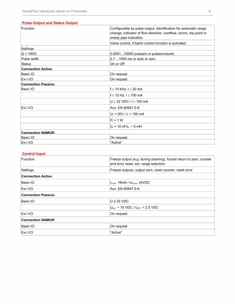
Pulse Output and Status Output
Function Configurable as pulse output, identification for automatic range change, indicator of flow direction, overflow, errors, trip point or empty pipe indication
Valve control, if batch control function is activated
Settings
Q = 100% 0.0001...10000 pulses/s or pulses/volume
Pulse width 0.1 ...1000 ms or auto or sym.
Status On or Off
Connection Active:
Basic IO On request
Ex-I I/O On request
Connection Passive: Basic IO f 10 kHz: I 20 mA
f 10 Hz: I 100 mA
U 32 VDC / I 100 mA
Ex-I I/O Acc. EN 60947-5-6
Ui = 30V / Ii = 100 mA
Pi = 1 W
Ci = 10 nF/Li ~ 0 mH
Connection NAMUR: Basic IO On request
Ex-I I/O "Active"
Control Input
Function Freeze output (e.g. during cleaning), forced return to zero, counter and error reset, ext. range selection.
Settings Freeze outputs, output zero, reset counter, reset error
Connection Active:
Basic IO lnom 16mA / Unom 24VDC
Ex-I I/O Acc. EN 60947-5-6
Connection Passive:
Basic IO U d 32 VDC
Uon ~ 19 VDC / Uof f < 2.5 VDC
Ex-I I/O On request
Connection NAMUR:
Basic IO On request
Ex-I I/O "Active"
HFS Catalog_Without Tab_HighRes.pdf 1036 6/8/2011 12:41:48 PM
VersaFlow Ultrasonic clamp-on Flowmeter 7
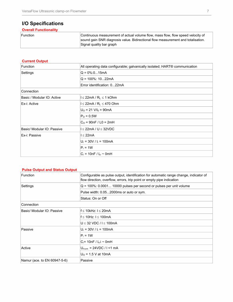
I/O Specifications Overall Functionality
Function Continuous measurement of actual volume flow, mass flow, flow speed velocity of sound gain SNR diagnosis value. Bidirectional flow measurement and totalisation. Signal quality bar graph
Current Output
Function All operating data configurable; galvanically isolated; HART® communication
Settings Q = 0%:0...15mA
Q = 100%: 10...22mA
Error identification: 0...22mA
Connection
Basic / Modular IO: Active l 22mA / RL 1 kOhm
Ex-i: Active l 22mA / RL 470 Ohm
UO = 21 V/l0 = 90mA
PO = 0.5W
CO = 90nF / L0 = 2mH
Basic/ Modular IO: Passive l 22mA / U 32VDC
Ex-i: Passive I 22mA
Ui = 30V / li = 100mA
Pi = 1W
Ci = 10nF / Li ~ 0mH
Pulse Output and Status Output
Function Configurable as pulse output, identification for automatic range change, indicator of flow direction, overflow, errors, trip point or empty pipe indication
Settings Q = 100%: 0.0001... 10000 pulses per second or pulses per unit volume
Pulse width: 0.05...2000ms or auto or sym.
Status: On or Off
Connection
Basic/ Modular IO: Passive f 10kHz: I 20mA
f 10Hz: I 100mA
U 32 VDC / l 100mA
Passive Ui = 30V / li = 100mA
Pi = 1W
Ci= 10nF / Li i ~ 0mH
Active Unom = 24VDC / l <1 mA
UO = 1.5 V at 10mA
Namur (ace. to EN 60947-5-6) Passive
HFS Catalog_Without Tab_HighRes.pdf 1037 6/8/2011 12:41:48 PM
VersaFlow Ultrasonic clamp-on Flowmeter 8
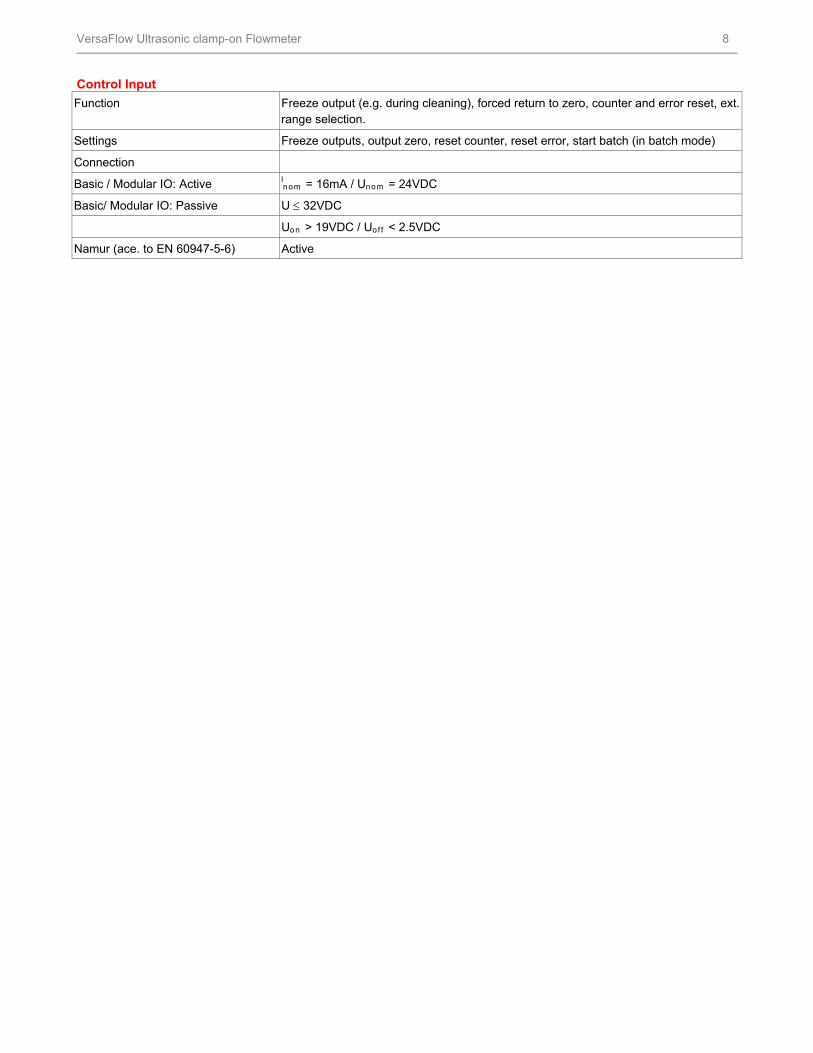
Control Input
Function Freeze output (e.g. during cleaning), forced return to zero, counter and error reset, ext. range selection.
Settings Freeze outputs, output zero, reset counter, reset error, start batch (in batch mode)
Connection
Basic / Modular IO: Active lnom = 16mA / Unom = 24VDC
Basic/ Modular IO: Passive U 32VDC
Uon > 19VDC / Uof f < 2.5VDC
Namur (ace. to EN 60947-5-6) Active
HFS Catalog_Without Tab_HighRes.pdf 1038 6/8/2011 12:41:48 PM
VersaFlow Ultrasonic clamp-on Flowmeter 9
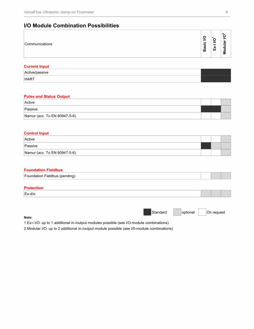
I/O Module Combination Possibilities
Communications
Bas
ic I/
O
Ex-
I I/O
1
Mo
du
lar
I/O2
Current Input
Active/passive
HART
Pulse and Status Output
Active
Passive
Namur (acc. To EN 60947-5-6)
Control Input
Active
Passive
Namur (acc. To EN 60947-5-6)
Foundation Fieldbus
Foundation Fieldbus (pending)
Protection
Ex-d/e
Standard optional On request Note:
1 Ex-i I/O: up to 1 additional in-/output modules possible (see l/O-module combinations)
2 Modular I/O: up to 2 additional in-/output module possible (see l/0-module combinations)
HFS Catalog_Without Tab_HighRes.pdf 1039 6/8/2011 12:41:48 PM
VersaFlow Ultrasonic clamp-on Flowmeter 10
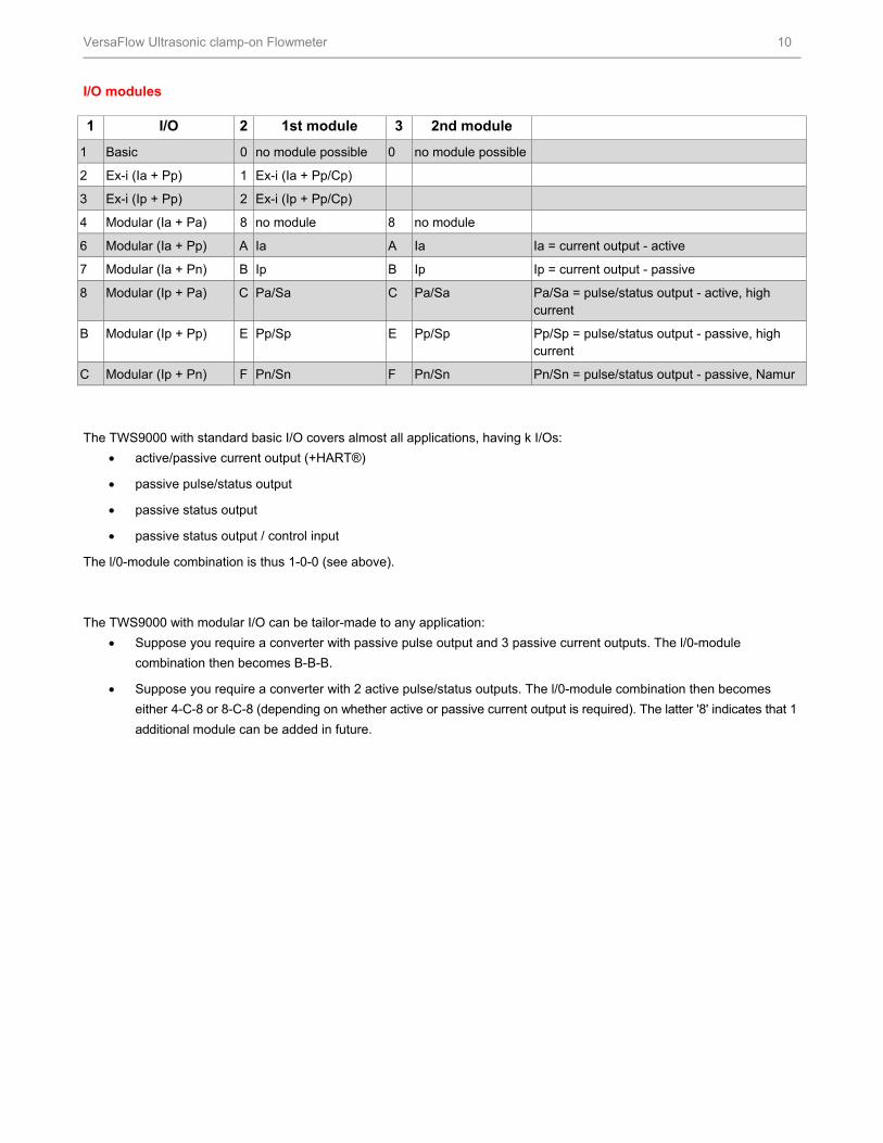
I/O modules 1 I/O 2 1st module 3 2nd module
1 Basic 0 no module possible 0 no module possible
2 Ex-i (Ia + Pp) 1 Ex-i (Ia + Pp/Cp)
3 Ex-i (Ip + Pp) 2 Ex-i (Ip + Pp/Cp)
4 Modular (Ia + Pa) 8 no module 8 no module
6 Modular (Ia + Pp) A Ia A Ia Ia = current output - active
7 Modular (Ia + Pn) B Ip B Ip Ip = current output - passive
8 Modular (Ip + Pa) C Pa/Sa C Pa/Sa Pa/Sa = pulse/status output - active, high current
B Modular (Ip + Pp) E Pp/Sp E Pp/Sp Pp/Sp = pulse/status output - passive, high current
C Modular (Ip + Pn) F Pn/Sn F Pn/Sn Pn/Sn = pulse/status output - passive, Namur
The TWS9000 with standard basic I/O covers almost all applications, having k I/Os:
active/passive current output (+HART®)
passive pulse/status output
passive status output
passive status output / control input
The l/0-module combination is thus 1-0-0 (see above).
The TWS9000 with modular I/O can be tailor-made to any application:
Suppose you require a converter with passive pulse output and 3 passive current outputs. The l/0-module
combination then becomes B-B-B.
Suppose you require a converter with 2 active pulse/status outputs. The l/0-module combination then becomes
either 4-C-8 or 8-C-8 (depending on whether active or passive current output is required). The latter '8' indicates that 1
additional module can be added in future.
HFS Catalog_Without Tab_HighRes.pdf 1040 6/8/2011 12:41:48 PM

VersaFlow Ultrasonic clamp-on Flowmeter 11
Example for Combination of I/O’s
Basic I/O Ex-I/O 1 2 3 1 2 3
1 0 0 2 0 0
1 2
3 0 0
1 2
D 0 0
1 2
E 0 0
1 2
Modular I/O 1 2 3 1 2 3 1 2 3
4 8 8 8 8 8 D 8 8
A B B 8 A 8
A B A
C C C
G G K
C 8 C 8 C 8
C C C
G G K
G 8 G 8 K 8
G G K
6 8 8 C 8 8 E 8 8
A 8 B 8 A 8
A B A
E E C
K K K
E 8 E 8 C 8
E E C
K K K
K 8 H 8 K 8
K H K
7 8 8 C 8 8 F 8 0
A 8 B 8 A
A B B
F F C
H H D
F 8 F 8 E
F F F
H H G
H 8 H 8 H
H H K
HFS Catalog_Without Tab_HighRes.pdf 1041 6/8/2011 12:41:49 PM
VersaFlow Ultrasonic clamp-on Flowmeter 12
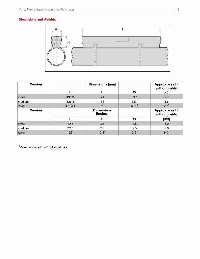
Dimensions and Weights
Version Dimensions [mm] Approx. weight (without cable /
L H W [kg]
small 496.3 71 63.1 2.7
medium 826.3 71 63.1 3.6
large 496.3 1 711 63.11 2.71
Version Dimensions [inches]
Approx. weight (without cable /
t i )L H W [lbs]
small 19.5 2.8 2.5 6.0
medium 32.5 2.8 2.5 7.9
large 19.51 2.81 2.51 6.01
1Value for one of the 2 delivered rails
HFS Catalog_Without Tab_HighRes.pdf 1042 6/8/2011 12:41:49 PM
VersaFlow Ultrasonic clamp-on Flowmeter 13
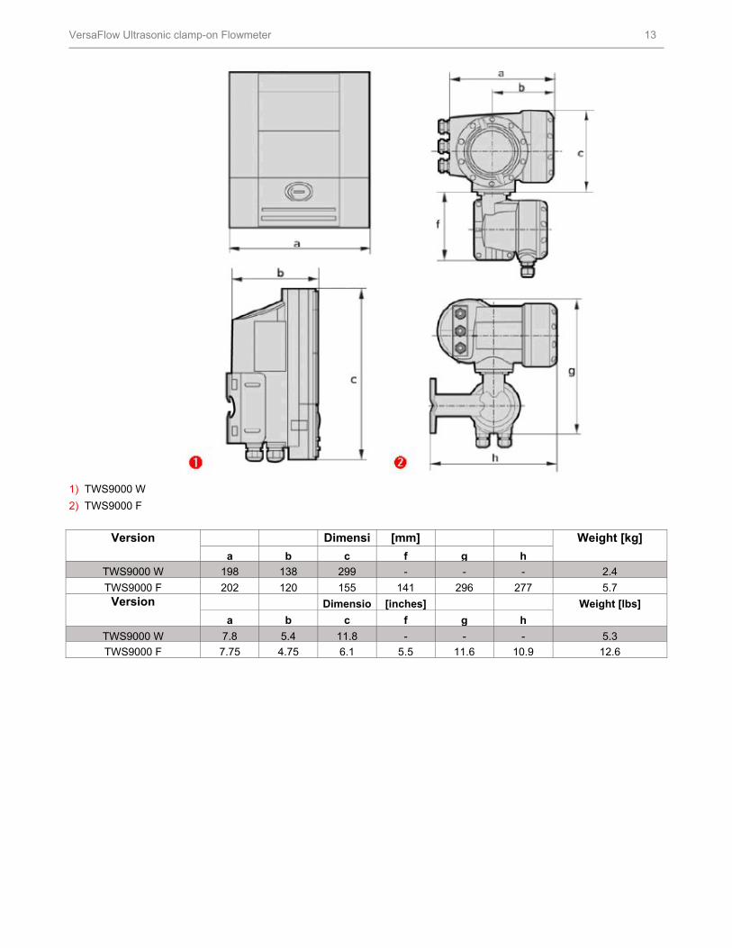
1) TWS9000 W
2) TWS9000 F
Version Dimensi [mm] Weight [kg]
a b c f g h
TWS9000 W 198 138 299 - - - 2.4
TWS9000 F 202 120 155 141 296 277 5.7Version Dimensio [inches] Weight [lbs]
a b c f g h
TWS9000 W 7.8 5.4 11.8 - - - 5.3
TWS9000 F 7.75 4.75 6.1 5.5 11.6 10.9 12.6
HFS Catalog_Without Tab_HighRes.pdf 1043 6/8/2011 12:41:49 PM
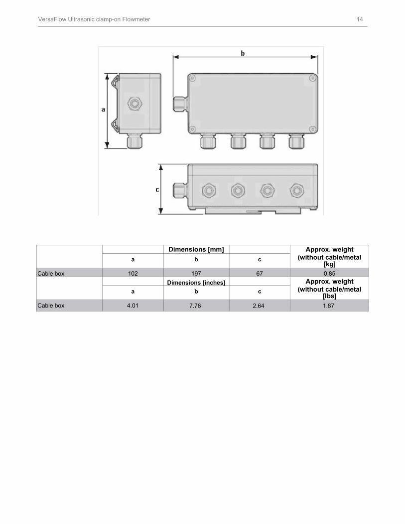
VersaFlow Ultrasonic clamp-on Flowmeter 14
Dimensions [mm] Approx. weight (without cable/metal
[kg] a b c
Cable box 102 197 67 0.85
Dimensions [inches] Approx. weight (without cable/metal
[lbs] a b c
Cable box 4.01 7.76 2.64 1.87
HFS Catalog_Without Tab_HighRes.pdf 1044 6/8/2011 12:41:49 PM
VersaFlow Ultrasonic clamp-on Flowmeter 15
For More Information
Learn more about how Honeywell’s VersaFlow
Ultrasonic clamp-on Flowmeter can provide long term
reliability, visit our website www.honeywell.com/ps/hfs or
contact your Honeywell account manager.
Honeywell Process Solutions
1860 West Rose Garden Lane
Phoenix, Arizona 85027
Tel: 1-800-423-9883 or 1-800-343-0228 www.honeywell.com/ps
Specifications are subject to change without notice.
34-VF-03-14September 2009 © 2010 Honeywell International Inc.
HFS Catalog_Without Tab_HighRes.pdf 1045 6/8/2011 12:41:49 PM