Verification of Numerical Modeling in Buried Pipelines ... · This paper investigates the responses...
9
Verification of Numerical Modeling in Buried Pipelines under Large Fault Movements by Small-Scale Experiments T.J. Lin, G.Y. Liu, L.L. Chung, and C.H. Chou National Center for Research on Earthquake Engineering, Taiwan C.W. Huang Dept. of Civil Engineering, Chung Yuan Christian University, Taiwan SUMMARY: This paper investigates the responses of buried pipelines under large fault movements using numerical models and small-scale experiments. The well-designed small-scale shear boxes experiments can induce the soil-pipeline interaction under fault displacements. The numerical models built up by ABAQUS commercial software are able to simulate the behavior of small-scale shear boxes experiments considering different types of soil and pipelines. A comprehensive and reliable numerical simulation to this problem requires experimental data to calibrate and verify three dimension responses of pipelines subjected to axial and flexural loadings. Finally, recommendations and future works are proposed for the design of small-scale experiments and numerical models. Keywords: large fault movements, pipelines, numerical simulation, small- scale experiments, local buckling 1. INTRODUCTION Earthquakes may induce serious damages to the structural integrity of buried pipelines. The main damage mechanisms of buried pipelines are generally from permanent ground deformation or seismic wave propagation. Disaster investigations have discovered the majority damages to continuous pipelines were caused by permanent ground deformation, such as fault movements, landslides, and liquefaction-induced lateral spread, which is within the relatively small geographic areas. On the other hand, seismic wave propagation can affect large geographic areas with relatively low damage ratio that is represented by the number of leaks per unit length of pipeline. Given the impact of pipeline systems on human life and the irrecoverable ecological disaster that may result from leakage of environmentally hazardous materials, the verification of seismic strength of buried pipelines at fault crossings has obviously become the top priorities of design. Newmark and Hall (1975) were one of the first to develop simplified analysis methods for the pipelines subjected to fault crossing problem. They considered a model in which a pipeline intersects a right-lateral strike-slip fault at an angle so that the pipe is primarily subjected to tensile strain. Closed form solutions to the pipe-soil interaction problem based on the elastic foundation theory were proposed by Kennedy et al. (1978) and Wang and Yeh (1985). The effects of lateral interaction at the pipe-soil interface and the influence of large axial strains on the bending stiffness of the pipe were taken into account. Karamitros et al. (2011) proposed an analytical methodology which can deal with simple material nonlinearities and second-order effects for the stress-strain analysis of buried steel pipelines crossing active normal faults. Analytical methods are suitable for grasping the nature of problems; however they cannot be applied to the problems considering large fault movements or material nonlinearities. Ha et al. (2008) presented the results from four centrifuge tests designed to investigate the influence of pipe-fault orientation on pipe behavior under earthquake faulting. The test results show pipe axial strain is strongly influenced by the pipe-fault orientation angle, whereas the influence of pipe-fault orientation angle on pipe bending is minor. The measured pipe strains were shown to follow the trend predicted by the Kennedy model. O’Rourke et al. (2008) addressed large-scale testing of pipeline response to earthquake-induced ground rupture and pipeline system performance after earthquakes. The finite element method (FEM), which can account consistently for the nonlinear stress-strain response of the pipeline, the longitudinal and transverse soil resistance, and
Transcript of Verification of Numerical Modeling in Buried Pipelines ... · This paper investigates the responses...

Verification of Numerical Modeling in Buried Pipelines
under Large Fault Movements by Small-Scale Experiments T.J. Lin, G.Y. Liu, L.L. Chung, and C.H. Chou National Center for Research on Earthquake Engineering, Taiwan
C.W. Huang Dept. of Civil Engineering, Chung Yuan Christian University, Taiwan
SUMMARY: This paper investigates the responses of buried pipelines under large fault movements using numerical models and small-scale experiments. The well-designed small-scale shear boxes experiments can induce the soil-pipeline interaction under fault displacements. The numerical models built up by ABAQUS commercial software are able to simulate the behavior of small-scale shear boxes experiments considering different types of soil and pipelines. A comprehensive and reliable numerical simulation to this problem requires experimental data to calibrate and verify three dimension responses of pipelines subjected to axial and flexural loadings. Finally, recommendations and future works are proposed for the design of small-scale experiments and numerical models.
Keywords: large fault movements, pipelines, numerical simulation, small- scale experiments, local buckling 1. INTRODUCTION Earthquakes may induce serious damages to the structural integrity of buried pipelines. The main damage mechanisms of buried pipelines are generally from permanent ground deformation or seismic wave propagation. Disaster investigations have discovered the majority damages to continuous pipelines were caused by permanent ground deformation, such as fault movements, landslides, and liquefaction-induced lateral spread, which is within the relatively small geographic areas. On the other hand, seismic wave propagation can affect large geographic areas with relatively low damage ratio that is represented by the number of leaks per unit length of pipeline. Given the impact of pipeline systems on human life and the irrecoverable ecological disaster that may result from leakage of environmentally hazardous materials, the verification of seismic strength of buried pipelines at fault crossings has obviously become the top priorities of design. Newmark and Hall (1975) were one of the first to develop simplified analysis methods for the pipelines subjected to fault crossing problem. They considered a model in which a pipeline intersects a right-lateral strike-slip fault at an angle so that the pipe is primarily subjected to tensile strain. Closed form solutions to the pipe-soil interaction problem based on the elastic foundation theory were proposed by Kennedy et al. (1978) and Wang and Yeh (1985). The effects of lateral interaction at the pipe-soil interface and the influence of large axial strains on the bending stiffness of the pipe were taken into account. Karamitros et al. (2011) proposed an analytical methodology which can deal with simple material nonlinearities and second-order effects for the stress-strain analysis of buried steel pipelines crossing active normal faults. Analytical methods are suitable for grasping the nature of problems; however they cannot be applied to the problems considering large fault movements or material nonlinearities. Ha et al. (2008) presented the results from four centrifuge tests designed to investigate the influence of pipe-fault orientation on pipe behavior under earthquake faulting. The test results show pipe axial strain is strongly influenced by the pipe-fault orientation angle, whereas the influence of pipe-fault orientation angle on pipe bending is minor. The measured pipe strains were shown to follow the trend predicted by the Kennedy model. O’Rourke et al. (2008) addressed large-scale testing of pipeline response to earthquake-induced ground rupture and pipeline system performance after earthquakes. The finite element method (FEM), which can account consistently for the nonlinear stress-strain response of the pipeline, the longitudinal and transverse soil resistance, and

second-order effects induced by large displacements, has been popularly applied to the pipeline analyses. Vazouras et al. (2010) presented a rigorous FEM model to investigate the mechanical behavior of buried steel pipelines under strike-slip faults. The interacting soil-pipeline system is modeled by finite elements, which can account for large strains and displacements, nonlinear materials and special contact on the soil and pipelines interface. Due to high cost and time consuming of the large-scale experiments conduction shown as Fig. 1, the small-scale experiments are relatively convenient to set up and conducted as pre-experiments to the large-scale experiments. The experimental data might be affected by size and boundary conditions of the shear boxes, which is different from infinite boundary at real ground condition. However, through calibration between the experimental data and the numerical results, the influence of size effect and boundary conditions can be discussed in this work.
(a) (b) Figure 1 Large scale soil-pipeline test at Cornell University: (a) large-scale experiment; (b) hydraulic
structural actuators. In this study, the small-scale experiments were conducted in National Center for Research on Earthquake Engineering (NCREE) laboratory. Only strike-slip fault movements are applied by the shaking table. The selection of pipelines in the experiment has limits to material and size due to small-scale experiments. The axial and bending strains of pipelines and fault movement displacements can be measured during the experiments. The responses of buried pipelines subjected to large oblique-slip fault movements are investigated by the finite element analysis (ABAQUS 2011). Geometric and material nonlinearities are taken into account in the simulation. Parametric studies are carried out to investigate the effects of different buried conditions and soil types on the responses of buried ductile pipelines under large fault movements.
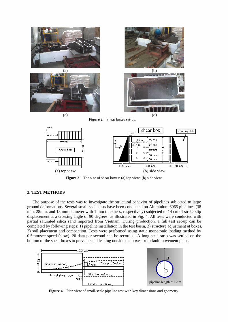
2. TEST SET-UP The small scale soil-pipelines tests were set-up at laboratory at National Center for Research on Earthquake Engineering (NCREE). Figures 2(a) and (b) shows one of the shear boxes was put on a small shaking table with a small hydraulic structural actuator (maximum 15 kN forces allowed) which can provide a one-way stroke displacement of 14 cm. Another shear box set up on a small manufactured platform can be adjusted to the same height as the shear box on a shacking table. Two shear boxes contact well to prevent sand leaking problem and also can move freely under fault displacements. The shear boxes were initially offset to allow for maximum soil pressure acting at the pipelines. Two small plates welded at the ends of pipeline were bolted on the walls at the shear boxes, shown as Figs. 2(c), and (d).
As shown as Fig.3 (a), the length, height, and width of each shear box are equal to 60 cm, 23 cm and 32 cm, respectively, which is 1/20 of the large-scale test performed at Cornell University. The triangle stiffeners were built up along the two sides of outside the shear boxes to increase the strength of shear boxes at the open ends. The wider retaining plates were designed to prevent sand leaking problem when the shear box was moved. Eight slotted holes (4 holes per row) were drilled at the close end of shear boxes to connect to two small plates thermally welded to the ends of pipes, shown as Fig. 3(b).
(a) (b)
(c) (d)
Figure 2 Shear boxes set-up.
(a) top view (b) side view
Figure 3 The size of shear boxes: (a) top view; (b) side view. 3. TEST METHODS The purpose of the tests was to investigate the structural behavior of pipelines subjected to large ground deformations. Several small-scale tests have been conducted on Aluminium 6065 pipelines (38 mm, 28mm, and 18 mm diameter with 1 mm thickness, respectively) subjected to 14 cm of strike-slip displacement at a crossing angle of 90 degrees, as illustrated in Fig. 4. All tests were conducted with partial saturated silica sand imported from Vietnam. During production, a full test set-up can be completed by following steps: 1) pipeline installation in the test basin, 2) structure adjustment at boxes, 3) soil placement and compaction. Tests were performed using static monotonic loading method by 0.5mm/sec speed (slow). 20 data per second can be recorded. A long steel strip was settled on the bottom of the shear boxes to prevent sand leaking outside the boxes from fault movement place.
pipeline length = 1.2 m
D
t B
Figure 4 Plan view of small-scale pipeline test with key dimensions and geometry.
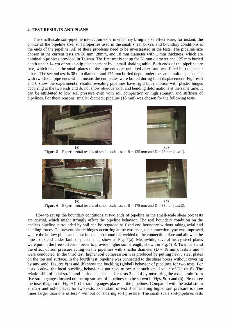
4. TEST RESULTS AND PLANS The small-scale soil-pipeline interaction experiments may bring a size effect issue, for instant: the choice of the pipeline size, soil properties used in the small shear boxes, and boundary conditions at the ends of the pipeline. All of these problems need to be investigated in the tests. The pipeline size chosen in the current tests are 38 mm, 28mm, and 18 mm diameter with 1 mm thickness, which are nominal pipe sizes provided in Taiwan. The first test is set up for 28 mm diameter and 125 mm buried depth under 14 cm of strike-slip displacement by a small shaking table. Both ends of the pipeline are free, which means the small plates on the pipe ends are unbolted after sand was filled into the shear boxes. The second test is 38 mm diameter and 175 mm buried depth under the same fault displacement with two fixed pipe ends which means the end plates were bolted during fault displacement. Figures 5 and 6 show the experimental results revealing pipelines have rigid body motion with plastic hinges occurring at the two ends and do not show obvious axial and bending deformations at the same time. It can be attributed to low soil pressure even with soil compaction or high strength and stiffness of pipelines. For these reasons, smaller diameter pipeline (18 mm) was chosen for the following tests.
(a) (b)
Figure 5 Experimental results of small-scale test at B = 125 mm and D = 28 mm (test 1).
(a) (b)
Figure 6 Experimental results of small-scale test at B = 175 mm and D = 38 mm (test 2).
How to set up the boundary conditions at two ends of pipeline in the small-scale shear box tests are crucial, which might strongly affect the pipeline behavior. The real boundary condition on the endless pipeline surrounded by soil can be regarded as fixed end boundary without taking axial and bending forces. To prevent plastic hinges occurring at the two ends, the connection type was improved, where the hollow pipe can be put into a short round bar welded to the connection plate and allowed the pipe to extend under fault displacements, show as Fig. 7(a). Meanwhile, several heavy steel plates were put on the free surface in order to provide higher soil strength, shown in Fig. 7(b). To understand the effect of soil pressure acting on the pipelines with smaller diameter (D = 18 mm), tests 3 and 4 were conducted. In the third test, higher soil compression was produced by putting heavy steel plates on the top soil surface. In the fourth test, pipeline was connected to the shear boxes without covering by any sand. Figures 8(a) and (b) show the buckling (global) behavior of pipelines for two tests. For tests 3 adn4, the local buckling behavior is not easy to occur at such small value of D/t (=18). The relationship of axial strain and fault displacement for tests 3 and 4 by measuring the axial strain from five strain gauges located on the top surface of pipelines can be shown in Figs. 9(a) and (b). Please see the inset diagram in Fig. 9 (b) for strain gauges places at the pipelines. Compared with the axial strain at m2-r and m2-l places for two tests, axial stain of test 3 considering higher soil pressure is three times larger than one of test 4 without considering soil pressure. The small scale soil-pipelines tests
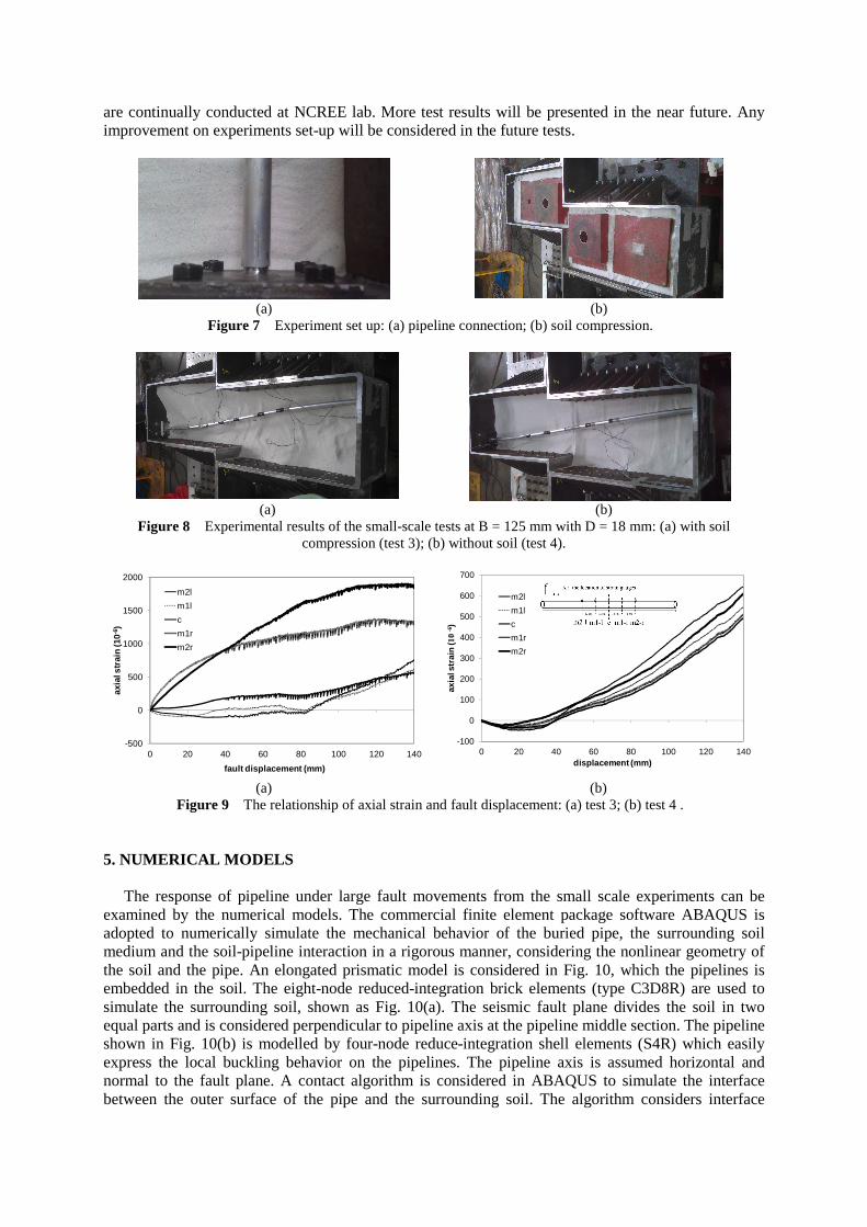
are continually conducted at NCREE lab. More test results will be presented in the near future. Any improvement on experiments set-up will be considered in the future tests.
(a) (b)
Figure 7 Experiment set up: (a) pipeline connection; (b) soil compression.
(a) (b)
Figure 8 Experimental results of the small-scale tests at B = 125 mm with D = 18 mm: (a) with soil compression (test 3); (b) without soil (test 4).
-500
0
500
1000
1500
2000
0 20 40 60 80 100 120 140
axia
l str
ain
(10-
6 )
fault displacement (mm)
m2l
m1l
c
m1r
m2r
-100
0
100
200
300
400
500
600
700
0 20 40 60 80 100 120 140
axia
l str
ain
(10
-6)
displacement (mm)
m2l
m1l
c
m1r
m2r
(a) (b)
Figure 9 The relationship of axial strain and fault displacement: (a) test 3; (b) test 4 . 5. NUMERICAL MODELS
The response of pipeline under large fault movements from the small scale experiments can be examined by the numerical models. The commercial finite element package software ABAQUS is adopted to numerically simulate the mechanical behavior of the buried pipe, the surrounding soil medium and the soil-pipeline interaction in a rigorous manner, considering the nonlinear geometry of the soil and the pipe. An elongated prismatic model is considered in Fig. 10, which the pipelines is embedded in the soil. The eight-node reduced-integration brick elements (type C3D8R) are used to simulate the surrounding soil, shown as Fig. 10(a). The seismic fault plane divides the soil in two equal parts and is considered perpendicular to pipeline axis at the pipeline middle section. The pipeline shown in Fig. 10(b) is modelled by four-node reduce-integration shell elements (S4R) which easily express the local buckling behavior on the pipelines. The pipeline axis is assumed horizontal and normal to the fault plane. A contact algorithm is considered in ABAQUS to simulate the interface between the outer surface of the pipe and the surrounding soil. The algorithm considers interface
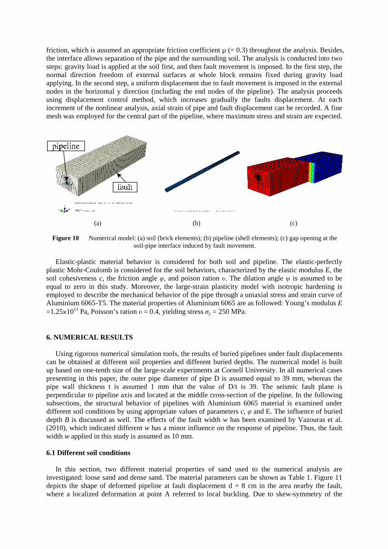
friction, which is assumed an appropriate friction coefficient µ (= 0.3) throughout the analysis. Besides, the interface allows separation of the pipe and the surrounding soil. The analysis is conducted into two steps: gravity load is applied at the soil first, and then fault movement is imposed. In the first step, the normal direction freedom of external surfaces at whole block remains fixed during gravity load applying. In the second step, a uniform displacement due to fault movement is imposed in the external nodes in the horizontal y direction (including the end nodes of the pipeline). The analysis proceeds using displacement control method, which increases gradually the faults displacement. At each increment of the nonlinear analysis, axial strain of pipe and fault displacement can be recorded. A fine mesh was employed for the central part of the pipeline, where maximum stress and strain are expected.
(a) (b) (c)
Figure 10 Numerical model: (a) soil (brick elements); (b) pipeline (shell elements); (c) gap opening at the soil-pipe interface induced by fault movement.
Elastic-plastic material behavior is considered for both soil and pipeline. The elastic-perfectly
plastic Mohr-Coulomb is considered for the soil behaviors, characterized by the elastic modulus E, the soil cohesiveness c, the friction angle φ, and poison ration υ. The dilation angle ψ is assumed to be equal to zero in this study. Moreover, the large-strain plasticity model with isotropic hardening is employed to describe the mechanical behavior of the pipe through a uniaxial stress and strain curve of Aluminium 6065-T5. The material properties of Aluminium 6065 are as followed: Young’s modulus E =1.25×10¹¹ Pa, Poisson’s ration υ = 0.4, yielding stress σy = 250 MPa. 6. NUMERICAL RESULTS
Using rigorous numerical simulation tools, the results of buried pipelines under fault displacements can be obtained at different soil properties and different buried depths. The numerical model is built up based on one-tenth size of the large-scale experiments at Cornell University. In all numerical cases presenting in this paper, the outer pipe diameter of pipe D is assumed equal to 39 mm, whereas the pipe wall thickness t is assumed 1 mm that the value of D/t is 39. The seismic fault plane is perpendicular to pipeline axis and located at the middle cross-section of the pipeline. In the following subsections, the structural behavior of pipelines with Aluminium 6065 material is examined under different soil conditions by using appropriate values of parameters c, φ and E. The influence of buried depth B is discussed as well. The effects of the fault width w has been examined by Vazouras et al. (2010), which indicated different w has a minor influence on the response of pipeline. Thus, the fault width w applied in this study is assumed as 10 mm.
6.1 Different soil conditions
In this section, two different material properties of sand used to the numerical analysis are investigated: loose sand and dense sand. The material parameters can be shown as Table 1. Figure 11 depicts the shape of deformed pipeline at fault displacement d = 8 cm in the area nearby the fault, where a localized deformation at point A referred to local buckling. Due to skew-symmetry of the
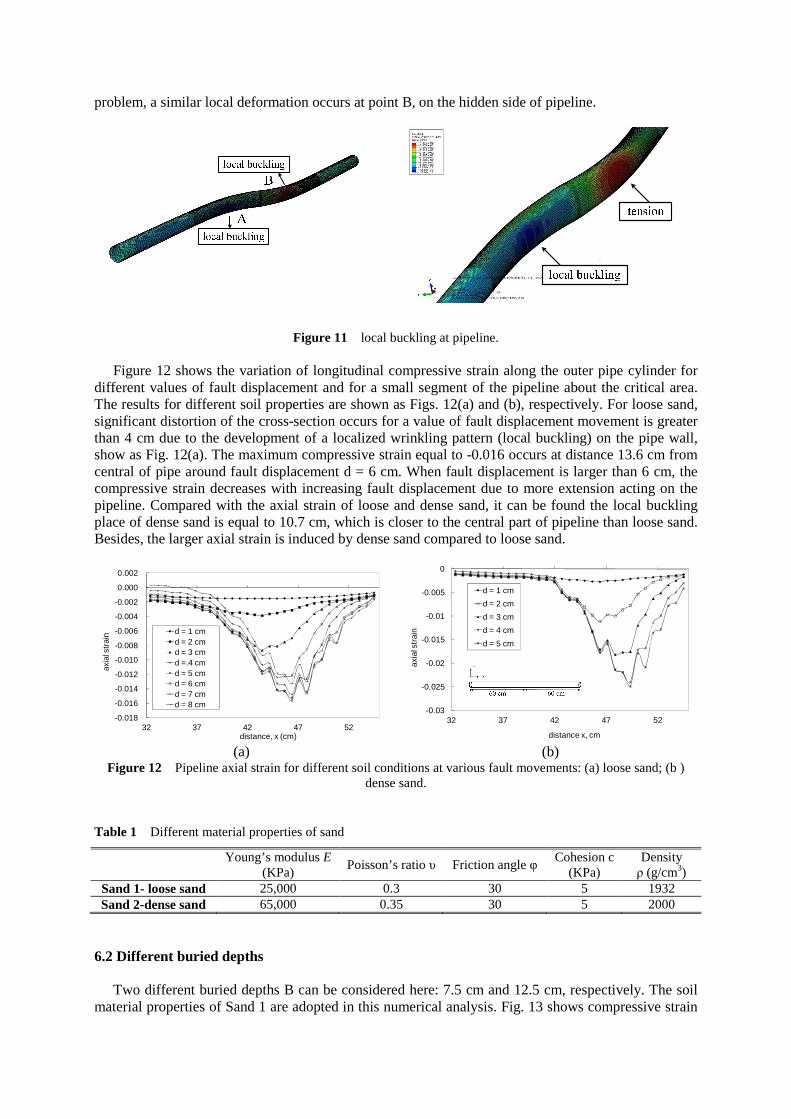
problem, a similar local deformation occurs at point B, on the hidden side of pipeline.
Figure 11 local buckling at pipeline.
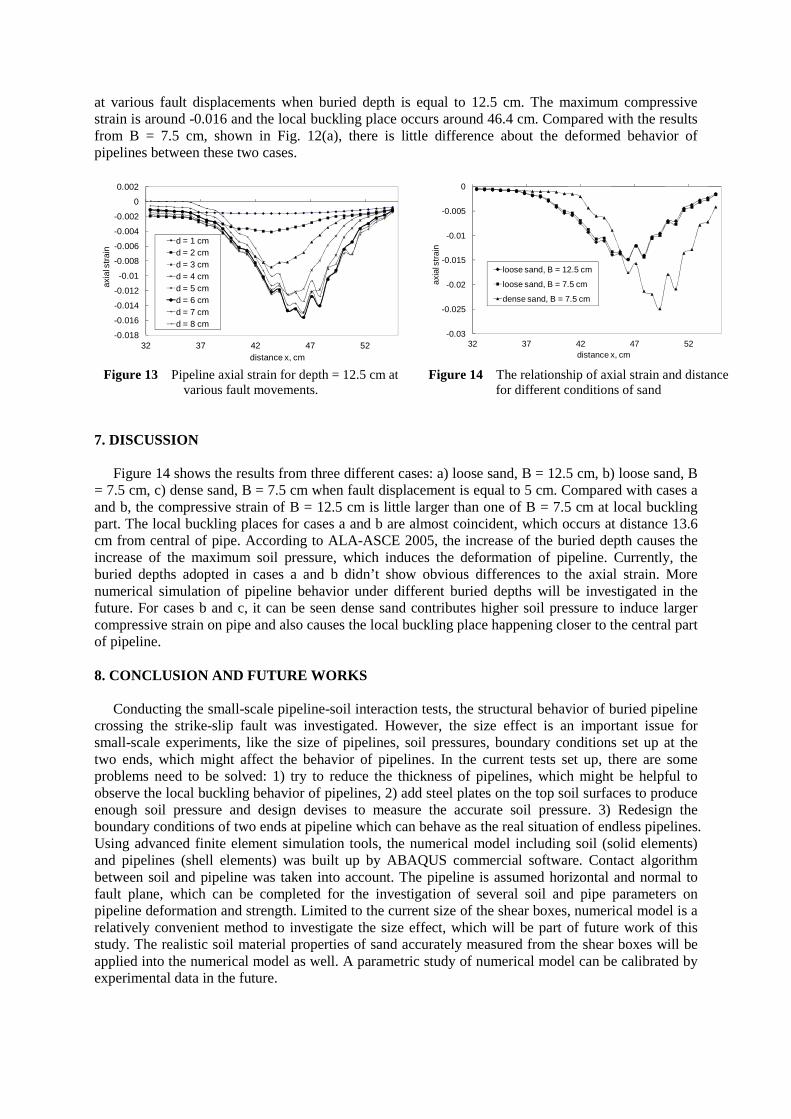
Figure 12 shows the variation of longitudinal compressive strain along the outer pipe cylinder for different values of fault displacement and for a small segment of the pipeline about the critical area. The results for different soil properties are shown as Figs. 12(a) and (b), respectively. For loose sand, significant distortion of the cross-section occurs for a value of fault displacement movement is greater than 4 cm due to the development of a localized wrinkling pattern (local buckling) on the pipe wall, show as Fig. 12(a). The maximum compressive strain equal to -0.016 occurs at distance 13.6 cm from central of pipe around fault displacement d = 6 cm. When fault displacement is larger than 6 cm, the compressive strain decreases with increasing fault displacement due to more extension acting on the pipeline. Compared with the axial strain of loose and dense sand, it can be found the local buckling place of dense sand is equal to 10.7 cm, which is closer to the central part of pipeline than loose sand. Besides, the larger axial strain is induced by dense sand compared to loose sand.
-0.018
-0.016
-0.014
-0.012
-0.010
-0.008
-0.006
-0.004
-0.002
0.000
0.002
32 37 42 47 52
axia
l str
ain
distance, x (cm)
d = 1 cmd = 2 cmd = 3 cmd =.4 cmd = 5 cmd = 6 cmd = 7 cmd = 8 cm
-0.03
-0.025
-0.02
-0.015
-0.01
-0.005
0
32 37 42 47 52
axia
l str
ain
distance x, cm
d = 1 cm
d = 2 cm
d = 3 cm
d = 4 cm
d = 5 cm
(a) (b)
Figure 12 Pipeline axial strain for different soil conditions at various fault movements: (a) loose sand; (b ) dense sand.
Table 1 Different material properties of sand
Young’s modulus E
(KPa) Poisson’s ratio υ Friction angle φ
Cohesion c (KPa)
Density ρ (g/cm3)
Sand 1- loose sand 25,000 0.3 30 5 1932 Sand 2-dense sand 65,000 0.35 30 5 2000
6.2 Different buried depths
Two different buried depths B can be considered here: 7.5 cm and 12.5 cm, respectively. The soil material properties of Sand 1 are adopted in this numerical analysis. Fig. 13 shows compressive strain
at various fault displacements when buried depth is equal to 12.5 cm. The maximum compressive strain is around -0.016 and the local buckling place occurs around 46.4 cm. Compared with the results from B = 7.5 cm, shown in Fig. 12(a), there is little difference about the deformed behavior of pipelines between these two cases.
-0.018
-0.016
-0.014
-0.012
-0.01
-0.008
-0.006
-0.004
-0.002
0
0.002
32 37 42 47 52
axia
l str
ain
distance x, cm
d = 1 cmd = 2 cmd = 3 cmd = 4 cmd = 5 cmd = 6 cmd = 7 cmd = 8 cm
-0.03
-0.025
-0.02
-0.015
-0.01
-0.005
0
32 37 42 47 52
axia
l str
ain
distance x, cm
loose sand, B = 12.5 cm
loose sand, B = 7.5 cm
dense sand, B = 7.5 cm
Figure 13 Pipeline axial strain for depth = 12.5 cm at
various fault movements. Figure 14 The relationship of axial strain and distance
for different conditions of sand 7. DISCUSSION
Figure 14 shows the results from three different cases: a) loose sand, B = 12.5 cm, b) loose sand, B = 7.5 cm, c) dense sand, B = 7.5 cm when fault displacement is equal to 5 cm. Compared with cases a and b, the compressive strain of B = 12.5 cm is little larger than one of B = 7.5 cm at local buckling part. The local buckling places for cases a and b are almost coincident, which occurs at distance 13.6 cm from central of pipe. According to ALA-ASCE 2005, the increase of the buried depth causes the increase of the maximum soil pressure, which induces the deformation of pipeline. Currently, the buried depths adopted in cases a and b didn’t show obvious differences to the axial strain. More numerical simulation of pipeline behavior under different buried depths will be investigated in the future. For cases b and c, it can be seen dense sand contributes higher soil pressure to induce larger compressive strain on pipe and also causes the local buckling place happening closer to the central part of pipeline. 8. CONCLUSION AND FUTURE WORKS
Conducting the small-scale pipeline-soil interaction tests, the structural behavior of buried pipeline crossing the strike-slip fault was investigated. However, the size effect is an important issue for small-scale experiments, like the size of pipelines, soil pressures, boundary conditions set up at the two ends, which might affect the behavior of pipelines. In the current tests set up, there are some problems need to be solved: 1) try to reduce the thickness of pipelines, which might be helpful to observe the local buckling behavior of pipelines, 2) add steel plates on the top soil surfaces to produce enough soil pressure and design devises to measure the accurate soil pressure. 3) Redesign the boundary conditions of two ends at pipeline which can behave as the real situation of endless pipelines. Using advanced finite element simulation tools, the numerical model including soil (solid elements) and pipelines (shell elements) was built up by ABAQUS commercial software. Contact algorithm between soil and pipeline was taken into account. The pipeline is assumed horizontal and normal to fault plane, which can be completed for the investigation of several soil and pipe parameters on pipeline deformation and strength. Limited to the current size of the shear boxes, numerical model is a relatively convenient method to investigate the size effect, which will be part of future work of this study. The realistic soil material properties of sand accurately measured from the shear boxes will be applied into the numerical model as well. A parametric study of numerical model can be calibrated by experimental data in the future.

REFERENCES ABAQUS version 6.10 (2011). Analysis Users Manual. Providence, RI: Dassault Systèmes Simulia
Corporation. Abdoun, T. H., Ha, D., O'Rourke, M. J., Symans, M. D. O'Rourke, T. D. Palmer, M. C. and Harry, E. S. (2009).
Factors influencing the behavior of buried pipelines subjected to earthquake faulting. Soil Dyn. Earthqu. Eng. 29:3, 415-427.
American Lifelines Alliance-ASCE (2001). Guidelines for the design of buried steel pipe (with addenda through February 2005).
Elhmadi, K. and O'rourke, M. J. (1990). Seismic damage to segmented buried pipelines. Earthqu. Eng. Struct. Dyn. 19:4, 529-539.
Joshi, S., Prashant, A., Deb, A. and Jain, S. K. (2011). Analysis of buried pipelines subjected to reverse fault motion. Soil Dyn. Earthqu. Eng. 31:7, 930-940.
Ha, D., Abdoun, T. H., O'Rourke, M. J., Symans, M. D. O'Rourke, T. D., Palmer, M. C. and Harry, E. S. (2008a). Buried high-density polyethylene pipelines subjected to normal and strike-slip faulting-a centrifuge investigation. Can. Geotech. J. 45(12), 1733-1742.
Ha, D., Abdoun, T. H., O'Rourke, M. J., Symans, M. D. O'Rourke, T. D. Palmer, M. C. & Harry, E. S. 2008b "Centrifuge modeling of earthquake effects on buried high-density polyethylene (HDPE) pipelines crossing fault zones," ASCE J. Geotech. Geoenviron. Eng. 134:10, 1501-1515.
Karamitros, D. K., Bouckovalas, G. D. and Kouretzis, G. P. (2007). Stress analysis of buried steel pipelines at strike-slip fault crossings. Soil Dyn. Earthqu. Eng. 27:3, 200-211.
Kennedy, R. P., Chow, A. W. and Williamson, R. A. (1977). Fault movement effects on buried oil pipeline. J. Transp. Eng. Div., ASCE. 103:15, 617-633.
Olson, N. (2009) Soil Performance For Large Scale Soil-Pipeline Tests. PhD, Thesis. Cornell University. O’Rourke, T. D., Jezerski, J. M., Olson, N. A., Bonneau, A. L., Palmer, M. C., Stewart, H. E., O’Rourke, M. J.,
Abdoun, T. (2008). Geotechnics of pipeline system response to earthquakes, Proceedings of the Geotechnical Earthquake Engineering and Soil Dynamics IV Congress.
Palmer, M. C., O'Rourke, T. D., Olson, N. A., Abdoun, T. H., Ha, D. and O'Rourke, M. J. (2009). Tactile pressure sensors for soil-structure interaction assessment, ASCE J. Geotech. Geoenviron. Eng. 135:11, 1638-1645.
Trifonov, O. V. and Chernify, V. P. (2010). A semi-analytical approach to a nonlinear stress-strain analysis of buried steel pipelines crossing active faults. Soil Dyn. Earthqu. Eng. 30:11, 1298-1308.
Vazouras, P., Karamanos, S. A. and Dakoulas, P. (2010). Finite element analysis of buried steel pipelines under strike-slip fault displacements. Soil Dyn. Earthqu. Eng. 30:11, 1361-1376.
Wang, L. R. L. and Yeh, Y. (1985). A refined seismic analysis and design of buried pipeline for fault movement. Earthqu. Eng. Struct. Dyn. 13:1, 75-96.