Verification Manual - GEO5geo5-software.de/de/...wall_verification_manual_en.pdf · • calculation...
26
Verification Manual of GEO5 Gravity Wall program Written by: Ing. Veronika Vanˇ eˇ ckov´ a, Ph.D. Edited by: Ing. Jiˇ r´ ı Laurin Verze: 1.0-en © 1989 - 2009 Fine Ltd. www.finesotware.eu
Transcript of Verification Manual - GEO5geo5-software.de/de/...wall_verification_manual_en.pdf · • calculation...
Verification Manual
of GEO5 Gravity Wall program
Written by: Ing. Veronika Vaneckova, Ph.D.
Edited by: Ing. Jirı Laurin
Verze: 1.0-en
© 1989 - 2009 Fine Ltd.
www.finesotware.eu
INTRODUCTION
This Gravity Wall program Verification Manual contains hand-made calculation offollowing problems:
• calculation of earth pressures
• calculation of hydrodynamic pressure
• verification of the wall with the help of theory of limit states
• dimensioning of wall section according to EN 1992-1-1 [1]
• verification of the wall influenced by earthquake according to Mononobe-Okabetheory [2], [3]
In general this Verification Manual has been made to show the ability of the GEO5software to provide a solution consistent with the result of hand-made calculations ortextbook solutions.
Results of hand-made calculations are compared with the results from GEO5 GravityWall program.
For further details please refer to our verification example file (Demo.gtz – downloadhttp://www.finesoftware.eu/references/verification-manuals/) using our program GEO5Gravity Wall (http://www.finesoftware.eu/geotechnical-software/gravity-wall/).
Contents
1 Example 1 1
1.1 Problem description . . . . . . . . . . . . . . . . . . . . . . . . . . . . . . 1
1.2 Verification of the whole wall . . . . . . . . . . . . . . . . . . . . . . . . 1
1.3 Bearing capacity of the foundation soil . . . . . . . . . . . . . . . . . . . 11
1.4 Dimensioning - analysis of wall section . . . . . . . . . . . . . . . . . . . 11
1.5 Verification of the wall - influence of earthquake . . . . . . . . . . . . . . 16
1.6 Bearing capacity of the foundation soil . . . . . . . . . . . . . . . . . . . 23
Reference 23
Verification Manual GEO5 Gravity Wall
1 Example 1
1.1 Problem description
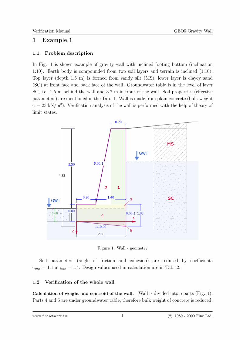
In Fig. 1 is shown example of gravity wall with inclined footing bottom (inclination
1:10). Earth body is compounded from two soil layers and terrain is inclined (1:10).
Top layer (depth 1.5 m) is formed from sandy silt (MS), lower layer is clayey sand
(SC) at front face and back face of the wall. Groundwater table is in the level of layer
SC, i.e. 1.5 m behind the wall and 3.7 m in front of the wall. Soil properties (effective
parameters) are mentioned in the Tab. 1. Wall is made from plain concrete (bulk weight
γ = 23 kN/m3). Verification analysis of the wall is performed with the help of theory of
limit states.
Figure 1: Wall - geometry
Soil parameters (angle of friction and cohesion) are reduced by coefficients
γmϕ = 1.1 a γmc = 1.4. Design values used in calculation are in Tab. 2.
1.2 Verification of the whole wall
Calculation of weight and centroid of the wall. Wall is divided into 5 parts (Fig. 1).
Parts 4 and 5 are under groundwater table, therefore bulk weight of concrete is reduced,
www.finesotware.eu 1 © 1989 - 2009 Fine Ltd.
Verification Manual GEO5 Gravity Wall
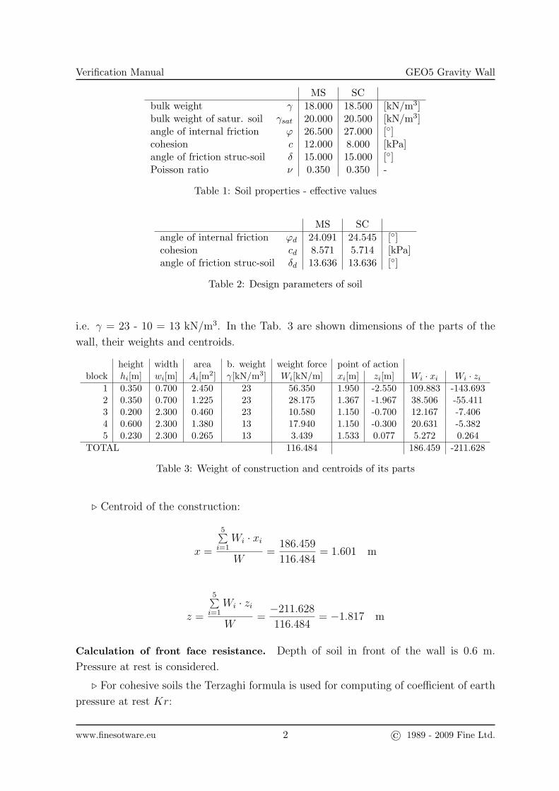
MS SCbulk weight γ 18.000 18.500 [kN/m3]bulk weight of satur. soil γsat 20.000 20.500 [kN/m3]angle of internal friction ϕ 26.500 27.000 [◦]cohesion c 12.000 8.000 [kPa]angle of friction struc-soil δ 15.000 15.000 [◦]Poisson ratio ν 0.350 0.350 -
Table 1: Soil properties - effective values
MS SCangle of internal friction ϕd 24.091 24.545 [◦]cohesion cd 8.571 5.714 [kPa]angle of friction struc-soil δd 13.636 13.636 [◦]
Table 2: Design parameters of soil
i.e. γ = 23 - 10 = 13 kN/m3. In the Tab. 3 are shown dimensions of the parts of the
wall, their weights and centroids.
height width area b. weight weight force point of actionblock hi[m] wi[m] Ai[m2] γ[kN/m3] Wi[kN/m] xi[m] zi[m] Wi · xi Wi · zi
1 0.350 0.700 2.450 23 56.350 1.950 -2.550 109.883 -143.6932 0.350 0.700 1.225 23 28.175 1.367 -1.967 38.506 -55.4113 0.200 2.300 0.460 23 10.580 1.150 -0.700 12.167 -7.4064 0.600 2.300 1.380 13 17.940 1.150 -0.300 20.631 -5.3825 0.230 2.300 0.265 13 3.439 1.533 0.077 5.272 0.264
TOTAL 116.484 186.459 -211.628
Table 3: Weight of construction and centroids of its parts
. Centroid of the construction:
x =
5∑i=1
Wi · xi
W=
186.459
116.484= 1.601 m
z =
5∑i=1
Wi · zi
W=−211.628
116.484= −1.817 m
Calculation of front face resistance. Depth of soil in front of the wall is 0.6 m.
Pressure at rest is considered.
. For cohesive soils the Terzaghi formula is used for computing of coefficient of earth
pressure at rest Kr:
www.finesotware.eu 2 © 1989 - 2009 Fine Ltd.
Verification Manual GEO5 Gravity Wall
Kr =ν
1− ν=
0.35
1− 0.35= 0.538
. Hydraulic gradient (hw - water tables difference, dd - seepage path downwards, du
- seepage path upwards):
i =hw
dd + du=
3.7− 1.5
3.03 + 0.6= 0.606
. Unit weight of soil in the area of ascending flow:
γ = γsat − γw − i · γw = 20.5− 10− 0.606 · 10 = 4.439 kN/m3
. Vertical normal effective stress σz in the footing bottom:
σz = γ · h = 4.439 · 0.6 = 2.664 kPa
. Pressure at rest σr in the footing bottom:
σr = Kr · σz = 0.538 · 2.664 = 1.434 kPa
. Resultant force of stress at rest Sr:
Sr =1
2· σr · h =
1
2· 1.434 · 0.6 = 0.430 kN/m
. Resultant force Sr is horizontally oriented, therefore:
Srx = Sr = 0.430 kN/m Srz = 0 kN/m
. Point of action of resultant force Sr:
x = 0 m
z = −h3
= −0.6
3= −0.200 m
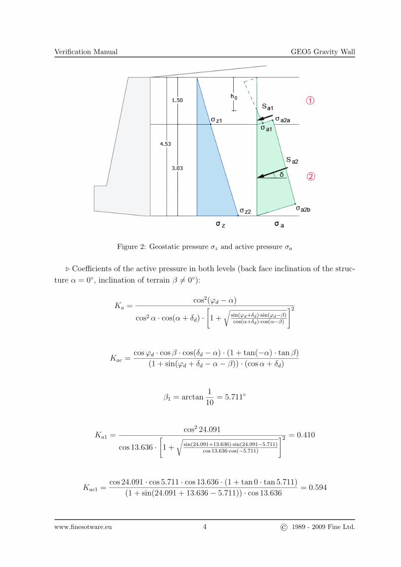
Calculation of active pressure. Construction is at interface between soils MS and SC
divided into two levels, in each is calculated geostatic pressure σz, active pressure σa
and resultant force Sa (Fig. 2).
www.finesotware.eu 3 © 1989 - 2009 Fine Ltd.
Verification Manual GEO5 Gravity Wall
Figure 2: Geostatic pressure σz and active pressure σa
. Coefficients of the active pressure in both levels (back face inclination of the struc-
ture α = 0◦, inclination of terrain β 6= 0◦):
Ka =cos2(ϕd − α)
cos2 α · cos(α+ δd) ·[1 +
√sin(ϕd+δd)·sin(ϕd−β)cos(α+δd)·cos(α−β)
]2
Kac =cosϕd · cos β · cos(δd − α) · (1 + tan(−α) · tan β)
(1 + sin(ϕd + δd − α− β)) · (cosα+ δd)
β1 = arctan1
10= 5.711◦
Ka1 =cos2 24.091
cos 13.636 ·[1 +
√sin(24.091+13.636)·sin(24.091−5.711)
cos 13.636·cos(−5.711)
]2 = 0.410
Kac1 =cos 24.091 · cos 5.711 · cos 13.636 · (1 + tan 0 · tan 5.711)
(1 + sin(24.091 + 13.636− 5.711)) · cos 13.636= 0.594
www.finesotware.eu 4 © 1989 - 2009 Fine Ltd.
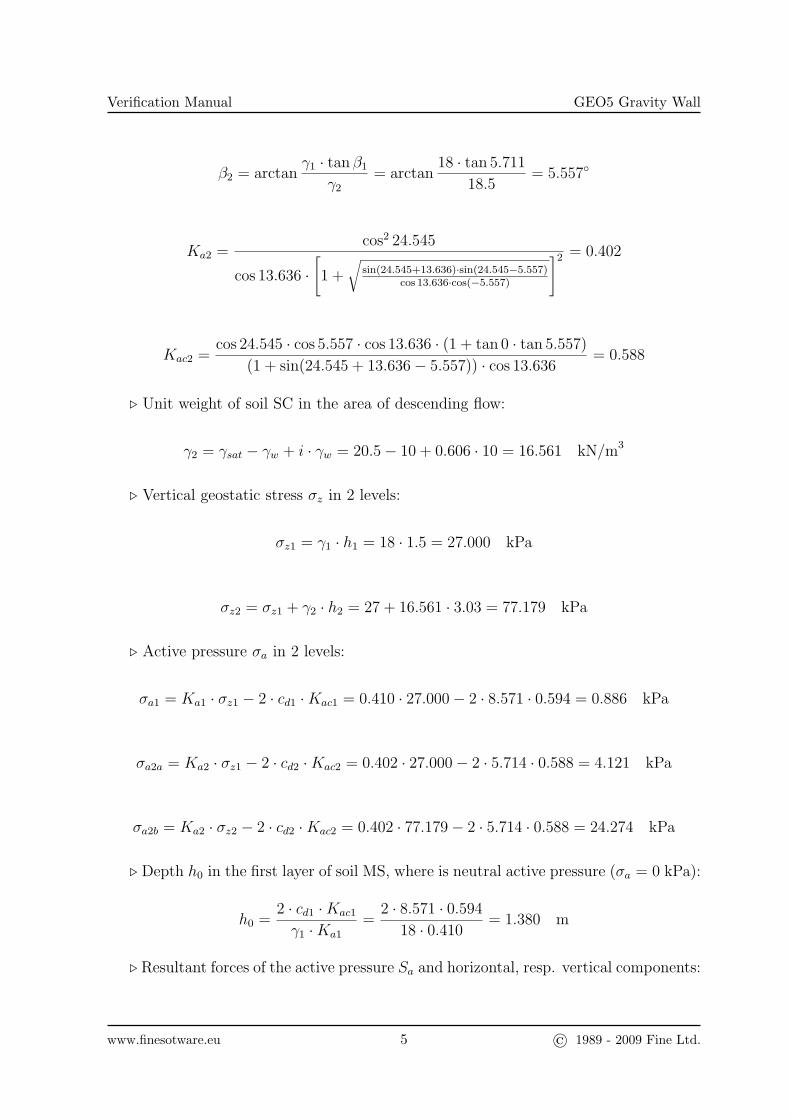
Verification Manual GEO5 Gravity Wall
β2 = arctanγ1 · tan β1
γ2
= arctan18 · tan 5.711
18.5= 5.557◦
Ka2 =cos2 24.545
cos 13.636 ·[1 +
√sin(24.545+13.636)·sin(24.545−5.557)
cos 13.636·cos(−5.557)
]2 = 0.402
Kac2 =cos 24.545 · cos 5.557 · cos 13.636 · (1 + tan 0 · tan 5.557)
(1 + sin(24.545 + 13.636− 5.557)) · cos 13.636= 0.588
. Unit weight of soil SC in the area of descending flow:
γ2 = γsat − γw + i · γw = 20.5− 10 + 0.606 · 10 = 16.561 kN/m3
. Vertical geostatic stress σz in 2 levels:
σz1 = γ1 · h1 = 18 · 1.5 = 27.000 kPa
σz2 = σz1 + γ2 · h2 = 27 + 16.561 · 3.03 = 77.179 kPa
. Active pressure σa in 2 levels:
σa1 = Ka1 · σz1 − 2 · cd1 ·Kac1 = 0.410 · 27.000− 2 · 8.571 · 0.594 = 0.886 kPa
σa2a = Ka2 · σz1 − 2 · cd2 ·Kac2 = 0.402 · 27.000− 2 · 5.714 · 0.588 = 4.121 kPa
σa2b = Ka2 · σz2 − 2 · cd2 ·Kac2 = 0.402 · 77.179− 2 · 5.714 · 0.588 = 24.274 kPa
. Depth h0 in the first layer of soil MS, where is neutral active pressure (σa = 0 kPa):
h0 =2 · cd1 ·Kac1
γ1 ·Ka1
=2 · 8.571 · 0.594
18 · 0.410= 1.380 m
. Resultant forces of the active pressure Sa and horizontal, resp. vertical components:
www.finesotware.eu 5 © 1989 - 2009 Fine Ltd.
Verification Manual GEO5 Gravity Wall
Sa1 = 0.5 · σa1 · (h1 − h0) = 0.5 · 0.886 · (1.5− 1.38) = 0.053 kN/m
Sax1 = Sa1 · cos δd1 = 0.053 · cos 13.636 = 0.052 kN/m
Saz1 = Sa1 · sin δd1 = 0.053 · sin 13.636 = 0.013 kN/m
Sa2 = 0.5 · (σa2b − σa2a) · h2 + σa2a · h2
Sa2 = 0.5 · (24.274− 4.121) · 3.03 + 4.121 · 3.03 = 43.019 kN/m
Sax2 = Sa2 · cos δd2 = 43.019 · cos 13.636 = 41.807 kN/m
Saz2 = Sa2 · sin δd2 = 43.019 · sin 13.636 = 10.142 kN/m
. Points of action of resultant forces Sa:
x1 = 2.300 m
z1 = −0.8− 2− (1.5− 1.38)
3= −2.840 m
x2 = 2.300 m
z2 = −
1
6· 3.032 · (24.274− 4.121) +
1
2· 3.032 · 4.121
1
2· 3.03 · (24.274− 4.121) + 3.03 · 4.121
+ 0.23 = −0.927 m
. Total resultant force of the active pressure Sa and horizontal, resp. vertical com-
ponent:
www.finesotware.eu 6 © 1989 - 2009 Fine Ltd.
Verification Manual GEO5 Gravity Wall
Sax =2∑i=1
Saxi = 0.052 + 41.807 = 41.859 kN/m
Saz =2∑i=1
Sazi = 0.013 + 10.142 = 10.155 kN/m
Sa =√S2ax + S2
az =√
41.8592 + 10.1552 = 43.073 kN/m
. Point of action of the resultant force Sa:
x =
2∑i=1
Sazi · xi
Saz=
0.029 + 23.327
10.155= 2.300 m
z =
2∑i=1
Saxi · zi
Sax=−0.147− 38.738
41.859= −0.929 m
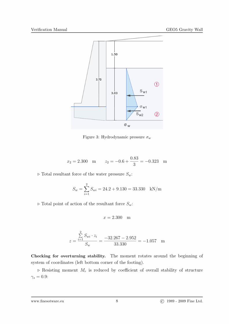
Calculation of water pressure. The heel of a structure is sunk into permeable subsoil,
which allows free water flow below the structure. Therefore acting of hydrodynamic
pressure is considered and its resultant force is calculated (Fig. 3).
. Horizontal water pressure σw at interface of level 1 and 2:
σw1 = γw · h1 = 10 · 2.2 = 22.000 kPa
. Resultant forces of water pressure Sw in 2 levels:
Sw1 =1
2· σw1 · h1 =
1
2· 22 · 2.2 = 24.200 kN/m
Sw2 =1
2· σw1 · h2 =
1
2· 22 · 0.83 = 9.130 kN/m
. Points of action of resultant forces:
x1 = 2.300 m z1 = −0.6− 2.2
3= −1.333 m
www.finesotware.eu 7 © 1989 - 2009 Fine Ltd.
Verification Manual GEO5 Gravity Wall
Figure 3: Hydrodynamic pressure σw
x2 = 2.300 m z2 = −0.6 +0.83
3= −0.323 m
. Total resultant force of the water pressure Sw:
Sw =2∑i=1
Swi = 24.2 + 9.130 = 33.330 kN/m
. Total point of action of the resultant force Sw:
x = 2.300 m
z =
2∑i=1
Swi · zi
Sw=−32.267− 2.952
33.330= −1.057 m
Checking for overturning stability. The moment rotates around the beginning of
system of coordinates (left bottom corner of the footing).
. Resisting moment Mr is reduced by coefficient of overall stability of structure
γs = 0.9:
www.finesotware.eu 8 © 1989 - 2009 Fine Ltd.
Verification Manual GEO5 Gravity Wall
Mr = 0.9 · (116.484 · 1.601 + 10.155 · 2.3) = 188.833 kNm/m
Result from program GEO5 Gravity Wall: Mr = 188.83 kNm/m
. Driving moment Mo:
Mo = −0.430 · 0.2 + 41.859 · 0.929 + 33.33 · 1.057 = 74.017 kNm/m
Result from program GEO5 Gravity Wall: Mo = 74.02 kNm/m
. Usage:
Vu =Mo
Mr
· 100 =74.017
188.833· 100 = 39.2 % O.K.
Result from program GEO5 Gravity Wall: Vu = 39.2 % O.K.
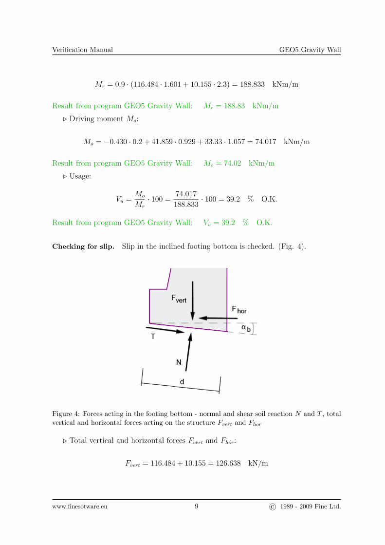
Checking for slip. Slip in the inclined footing bottom is checked. (Fig. 4).
Figure 4: Forces acting in the footing bottom - normal and shear soil reaction N and T , totalvertical and horizontal forces acting on the structure Fvert and Fhor
. Total vertical and horizontal forces Fvert and Fhor:
Fvert = 116.484 + 10.155 = 126.638 kN/m
www.finesotware.eu 9 © 1989 - 2009 Fine Ltd.
Verification Manual GEO5 Gravity Wall
Fhor = −0.430 + 41.859 + 33.330 = 74.758 kN/m
. Normal force in the footing bottom (inclination of footing bottom αb = 5.711◦, see
Fig. 4):
N = Fvert · cosαb + Fhor · sinαb
N = 126.638 · cos 5.711 + 74.758 · sin 5.711 = 133.449 kN/m
. Shear reaction in the footing bottom:
T = −Fvert · sinαb + Fhor · cosαb
T = −126.638 · sin 5.711 + 74.758 · cos 5.711 = 61.786 kN/m
. Eccentricity of the normal force (inclined width of the footing bottom d = 2.311
m):
e =d
2−
Mr
0.9−Mo
N=
2.311
2−
188.830
0.9− 74.017
133.449= 0.138 m
. Maximal allowable eccentricity:
ealw =d
3=
2.311
3= 0.770 m > e = 0.138 m O.K.
. Resisting force Hr:
Hr = γs · (N · tanϕd + cd · (d− 2 · e))
Hr = 0.9 · (133.449 · tan 24.545 + 5.714 · (2.311− 2 · 0.138)) = 65.316 kN/m
Result from program GEO5 Gravity Wall: Hr = 65.38 kN/m
. Driving force Hd:
www.finesotware.eu 10 © 1989 - 2009 Fine Ltd.
Verification Manual GEO5 Gravity Wall
Hd = T = 61.786 kN/m
Result from program GEO5 Gravity Wall: Hd = 61.79 kN/m
. Usage:
Vu =Hd
Hr
· 100 =61.786
65.316· 100 = 94.6 % O.K.
Result from program GEO5 Gravity Wall: Vu = 94.5 % O.K.
1.3 Bearing capacity of the foundation soil
Bearing capacity of the foundation soil is set as Rd = 100 kPa and is compared with
stress in the inclined footing bottom.
. Usage - eccentricity:
Vu =e
ealw· 100 =
0.138
0.770· 100 = 17.9 % O.K.
Result from program GEO5 Gravity Wall: Vu = 17.4 % O.K.
. Stress in the footing bottom:
σ =N
(d− 2 · e)=
133.449
(2.311− 2 · 0.138)= 65.570 kPa
Result from program GEO5 Gravity Wall: σ = 65.20 kPa
. Usage:
Vu =σ
Rd
· 100 =65.570
100· 100 = 65.57 % O.K.
Result from program GEO5 Gravity Wall: Vu = 65.2 % O.K.
1.4 Dimensioning - analysis of wall section
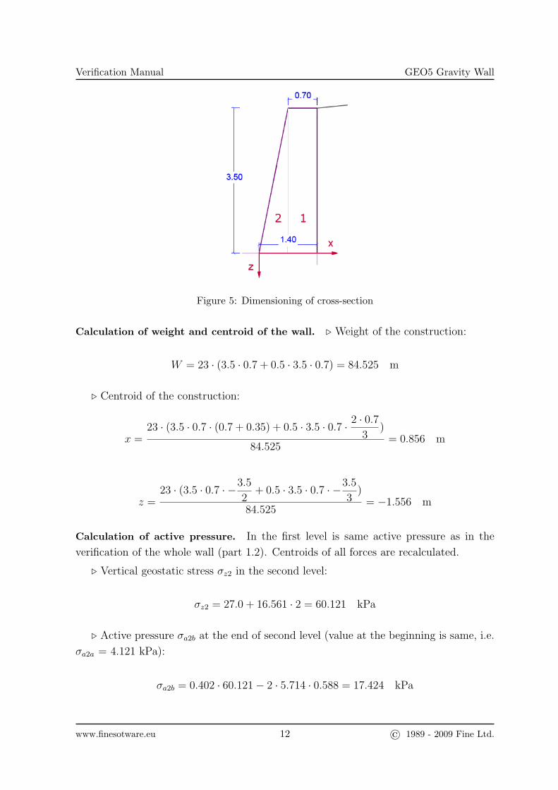
Cross-section in the level of the x-axis in Fig. 5 is analysed. Rectangular section (width
b = 1 m, height h = 1.4 m) is made from plain concrete C20/25 (characteristic strength
of concrete in tension fctk = 2200 kPa, characteristic cylindrical strength of concrete in
compression fck = 20000 kPa). Verification of cross-section made from plain concrete is
realized according to EN 1992 1-1 [1].
www.finesotware.eu 11 © 1989 - 2009 Fine Ltd.
Verification Manual GEO5 Gravity Wall
Figure 5: Dimensioning of cross-section
Calculation of weight and centroid of the wall. . Weight of the construction:
W = 23 · (3.5 · 0.7 + 0.5 · 3.5 · 0.7) = 84.525 m
. Centroid of the construction:
x =23 · (3.5 · 0.7 · (0.7 + 0.35) + 0.5 · 3.5 · 0.7 · 2 · 0.7
3)
84.525= 0.856 m
z =23 · (3.5 · 0.7 · −3.5
2+ 0.5 · 3.5 · 0.7 · −3.5
3)
84.525= −1.556 m
Calculation of active pressure. In the first level is same active pressure as in the
verification of the whole wall (part 1.2). Centroids of all forces are recalculated.
. Vertical geostatic stress σz2 in the second level:
σz2 = 27.0 + 16.561 · 2 = 60.121 kPa
. Active pressure σa2b at the end of second level (value at the beginning is same, i.e.
σa2a = 4.121 kPa):
σa2b = 0.402 · 60.121− 2 · 5.714 · 0.588 = 17.424 kPa
www.finesotware.eu 12 © 1989 - 2009 Fine Ltd.
Verification Manual GEO5 Gravity Wall
. Resultant force of the active pressure Sa2 and horizontal, resp. vertical component:
Sa2 = 0.5 · (17.424− 4.121) · 2 + 4.121 · 2 = 21.545 kN/m
Sax2 = Sa2 · cos δd2 = 21.545 · cos 13.636 = 20.938 kN/m
Saz2 = Sa2 · sin δd2 = 21.545 · sin 13.636 = 5.079 kN/m
. Points of action of resultant forces:
x1 = 1.400 m z1 = −2.84 + 0.8 = −2.040 m
x2 = 1.400 m
z2 = −0.5 · 4.121 · 22 +
1
6· (17.424− 4.121) · 22
4.121 · 2 + 0.5 · (17.424− 4.121) · 2= −0.794 m
. Total resultant force of the active pressure Sa and horizontal, resp. vertical com-
ponent:
Sax = 20.989 kN/m Saz = 5.092 kN/m Sa = 21.598 kN/m
. Point of action of resultant force Sa:
x = 1.400 m z =−2.040 · 0.052− 0.794 · 20.938
21.598= −0.797 m
Calculation of water pressure. Water pressure grows with height (h = 2 m).
. Horizontal water pressure σw in the level of analysed cross-section:
σw = γw · h = 10 · 2 = 20.000 kPa
. Resultant force of the water pressure Sw:
Sw =1
2· σw · h =
1
2· 20 · 2 = 20.000 kN/m
www.finesotware.eu 13 © 1989 - 2009 Fine Ltd.
Verification Manual GEO5 Gravity Wall
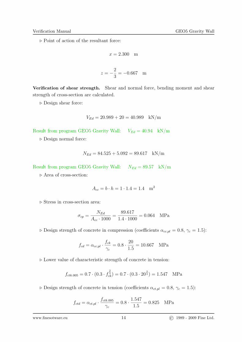
. Point of action of the resultant force:
x = 2.300 m
z = −2
3= −0.667 m
Verification of shear strength. Shear and normal force, bending moment and shear
strength of cross-section are calculated.
. Design shear force:
VEd = 20.989 + 20 = 40.989 kN/m
Result from program GEO5 Gravity Wall: VEd = 40.94 kN/m
. Design normal force:
NEd = 84.525 + 5.092 = 89.617 kN/m
Result from program GEO5 Gravity Wall: NEd = 89.57 kN/m
. Area of cross-section:
Acc = b · h = 1 · 1.4 = 1.4 m2
. Stress in cross-section area:
σcp =NEd
Acc · 1000=
89.617
1.4 · 1000= 0.064 MPa
. Design strength of concrete in compression (coefficients αcc.pl = 0.8, γc = 1.5):
fcd = αcc.pl ·fckγc
= 0.8 · 20
1.5= 10.667 MPa
. Lower value of characteristic strength of concrete in tension:
fctk.005 = 0.7 · (0.3 · f23ck) = 0.7 · (0.3 · 20
23 ) = 1.547 MPa
. Design strength of concrete in tension (coefficients αct.pl = 0.8, γc = 1.5):
fctd = αct.pl ·fctk.005
γc= 0.8 · 1.547
1.5= 0.825 MPa
www.finesotware.eu 14 © 1989 - 2009 Fine Ltd.
Verification Manual GEO5 Gravity Wall
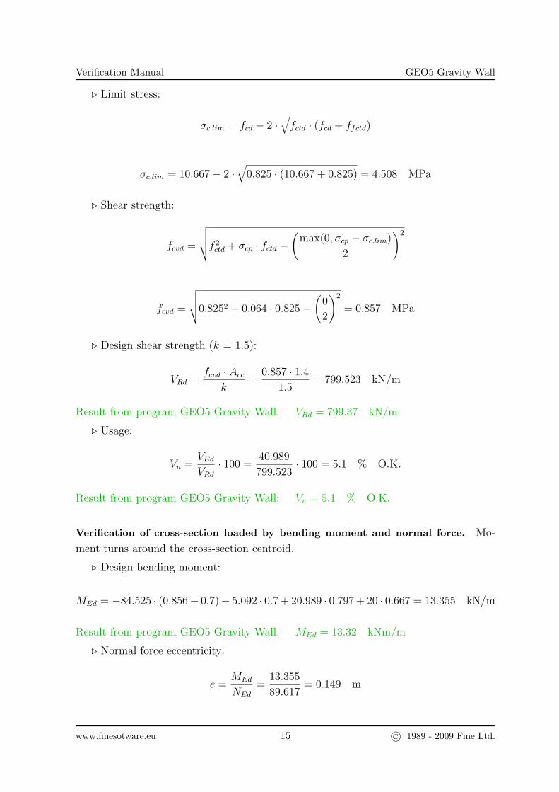
. Limit stress:
σc.lim = fcd − 2 ·√fctd · (fcd + ffctd)
σc.lim = 10.667− 2 ·√
0.825 · (10.667 + 0.825) = 4.508 MPa
. Shear strength:
fcvd =
√√√√f 2ctd + σcp · fctd −
(max(0, σcp − σc.lim)
2
)2
fcvd =
√√√√0.8252 + 0.064 · 0.825−(
0
2
)2
= 0.857 MPa
. Design shear strength (k = 1.5):
VRd =fcvd · Acc
k=
0.857 · 1.41.5
= 799.523 kN/m
Result from program GEO5 Gravity Wall: VRd = 799.37 kN/m
. Usage:
Vu =VEdVRd
· 100 =40.989
799.523· 100 = 5.1 % O.K.
Result from program GEO5 Gravity Wall: Vu = 5.1 % O.K.
Verification of cross-section loaded by bending moment and normal force. Mo-
ment turns around the cross-section centroid.
. Design bending moment:
MEd = −84.525 · (0.856− 0.7)− 5.092 · 0.7 + 20.989 · 0.797 + 20 · 0.667 = 13.355 kN/m
Result from program GEO5 Gravity Wall: MEd = 13.32 kNm/m
. Normal force eccentricity:
e =MEd
NEd
=13.355
89.617= 0.149 m
www.finesotware.eu 15 © 1989 - 2009 Fine Ltd.
Verification Manual GEO5 Gravity Wall
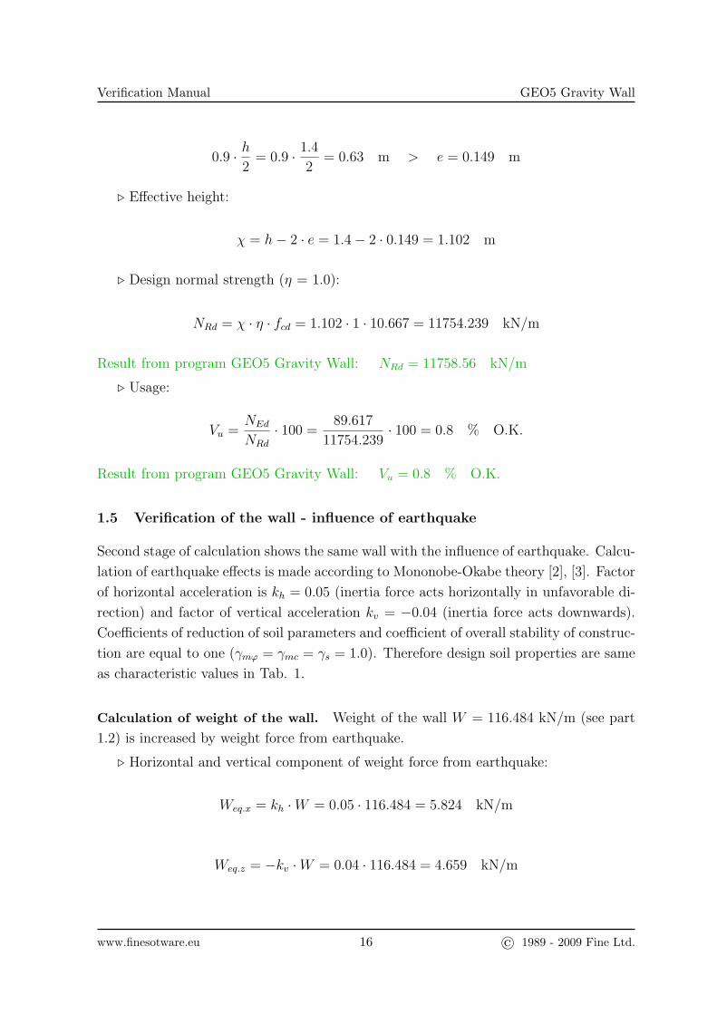
0.9 · h2
= 0.9 · 1.4
2= 0.63 m > e = 0.149 m
. Effective height:
χ = h− 2 · e = 1.4− 2 · 0.149 = 1.102 m
. Design normal strength (η = 1.0):
NRd = χ · η · fcd = 1.102 · 1 · 10.667 = 11754.239 kN/m
Result from program GEO5 Gravity Wall: NRd = 11758.56 kN/m
. Usage:
Vu =NEd
NRd
· 100 =89.617
11754.239· 100 = 0.8 % O.K.
Result from program GEO5 Gravity Wall: Vu = 0.8 % O.K.
1.5 Verification of the wall - influence of earthquake
Second stage of calculation shows the same wall with the influence of earthquake. Calcu-
lation of earthquake effects is made according to Mononobe-Okabe theory [2], [3]. Factor
of horizontal acceleration is kh = 0.05 (inertia force acts horizontally in unfavorable di-
rection) and factor of vertical acceleration kv = −0.04 (inertia force acts downwards).
Coefficients of reduction of soil parameters and coefficient of overall stability of construc-
tion are equal to one (γmϕ = γmc = γs = 1.0). Therefore design soil properties are same
as characteristic values in Tab. 1.
Calculation of weight of the wall. Weight of the wall W = 116.484 kN/m (see part
1.2) is increased by weight force from earthquake.
. Horizontal and vertical component of weight force from earthquake:
Weq.x = kh ·W = 0.05 · 116.484 = 5.824 kN/m
Weq.z = −kv ·W = 0.04 · 116.484 = 4.659 kN/m
www.finesotware.eu 16 © 1989 - 2009 Fine Ltd.
Verification Manual GEO5 Gravity Wall
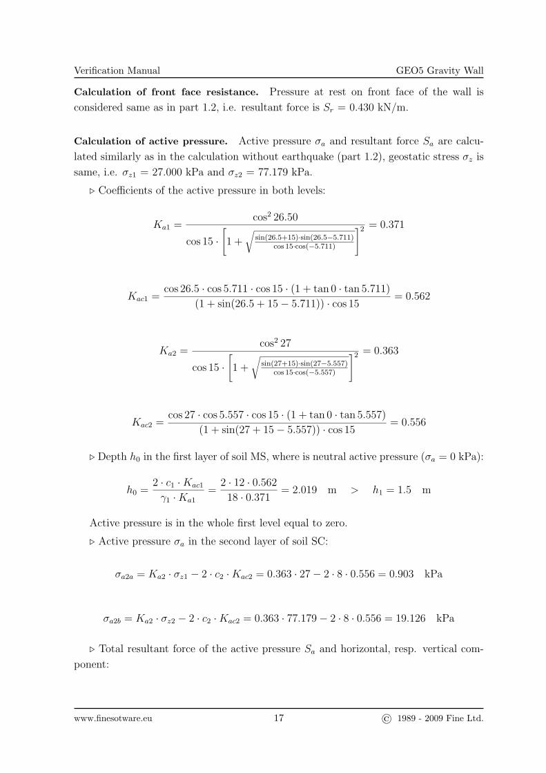
Calculation of front face resistance. Pressure at rest on front face of the wall is
considered same as in part 1.2, i.e. resultant force is Sr = 0.430 kN/m.
Calculation of active pressure. Active pressure σa and resultant force Sa are calcu-
lated similarly as in the calculation without earthquake (part 1.2), geostatic stress σz is
same, i.e. σz1 = 27.000 kPa and σz2 = 77.179 kPa.
. Coefficients of the active pressure in both levels:
Ka1 =cos2 26.50
cos 15 ·[1 +
√sin(26.5+15)·sin(26.5−5.711)
cos 15·cos(−5.711)
]2 = 0.371
Kac1 =cos 26.5 · cos 5.711 · cos 15 · (1 + tan 0 · tan 5.711)
(1 + sin(26.5 + 15− 5.711)) · cos 15= 0.562
Ka2 =cos2 27
cos 15 ·[1 +
√sin(27+15)·sin(27−5.557)
cos 15·cos(−5.557)
]2 = 0.363
Kac2 =cos 27 · cos 5.557 · cos 15 · (1 + tan 0 · tan 5.557)
(1 + sin(27 + 15− 5.557)) · cos 15= 0.556
. Depth h0 in the first layer of soil MS, where is neutral active pressure (σa = 0 kPa):
h0 =2 · c1 ·Kac1
γ1 ·Ka1
=2 · 12 · 0.562
18 · 0.371= 2.019 m > h1 = 1.5 m
Active pressure is in the whole first level equal to zero.
. Active pressure σa in the second layer of soil SC:
σa2a = Ka2 · σz1 − 2 · c2 ·Kac2 = 0.363 · 27− 2 · 8 · 0.556 = 0.903 kPa
σa2b = Ka2 · σz2 − 2 · c2 ·Kac2 = 0.363 · 77.179− 2 · 8 · 0.556 = 19.126 kPa
. Total resultant force of the active pressure Sa and horizontal, resp. vertical com-
ponent:
www.finesotware.eu 17 © 1989 - 2009 Fine Ltd.
Verification Manual GEO5 Gravity Wall
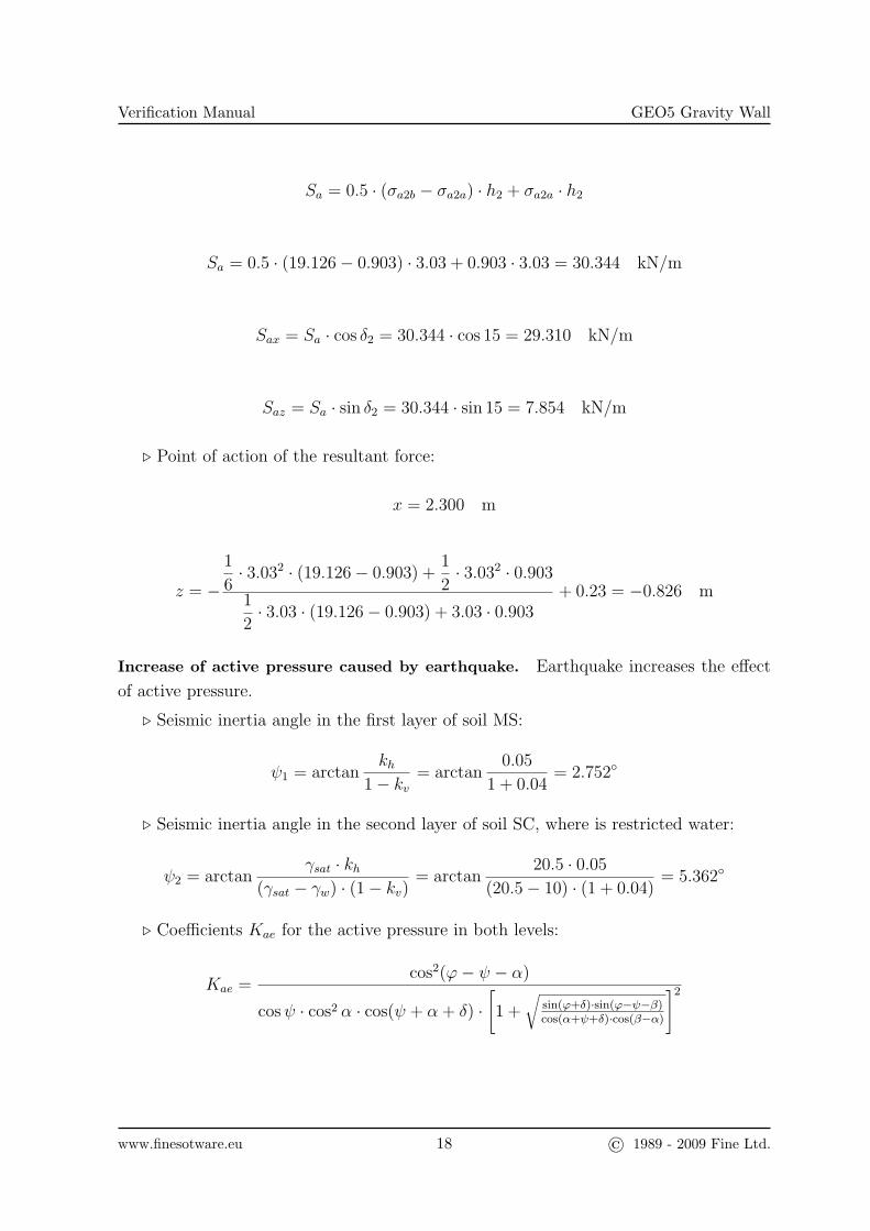
Sa = 0.5 · (σa2b − σa2a) · h2 + σa2a · h2
Sa = 0.5 · (19.126− 0.903) · 3.03 + 0.903 · 3.03 = 30.344 kN/m
Sax = Sa · cos δ2 = 30.344 · cos 15 = 29.310 kN/m
Saz = Sa · sin δ2 = 30.344 · sin 15 = 7.854 kN/m
. Point of action of the resultant force:
x = 2.300 m
z = −
1
6· 3.032 · (19.126− 0.903) +
1
2· 3.032 · 0.903
1
2· 3.03 · (19.126− 0.903) + 3.03 · 0.903
+ 0.23 = −0.826 m
Increase of active pressure caused by earthquake. Earthquake increases the effect
of active pressure.
. Seismic inertia angle in the first layer of soil MS:
ψ1 = arctankh
1− kv= arctan
0.05
1 + 0.04= 2.752◦
. Seismic inertia angle in the second layer of soil SC, where is restricted water:
ψ2 = arctanγsat · kh
(γsat − γw) · (1− kv)= arctan
20.5 · 0.05
(20.5− 10) · (1 + 0.04)= 5.362◦
. Coefficients Kae for the active pressure in both levels:
Kae =cos2(ϕ− ψ − α)
cosψ · cos2 α · cos(ψ + α+ δ) ·[1 +
√sin(ϕ+δ)·sin(ϕ−ψ−β)cos(α+ψ+δ)·cos(β−α)
]2
www.finesotware.eu 18 © 1989 - 2009 Fine Ltd.
Verification Manual GEO5 Gravity Wall
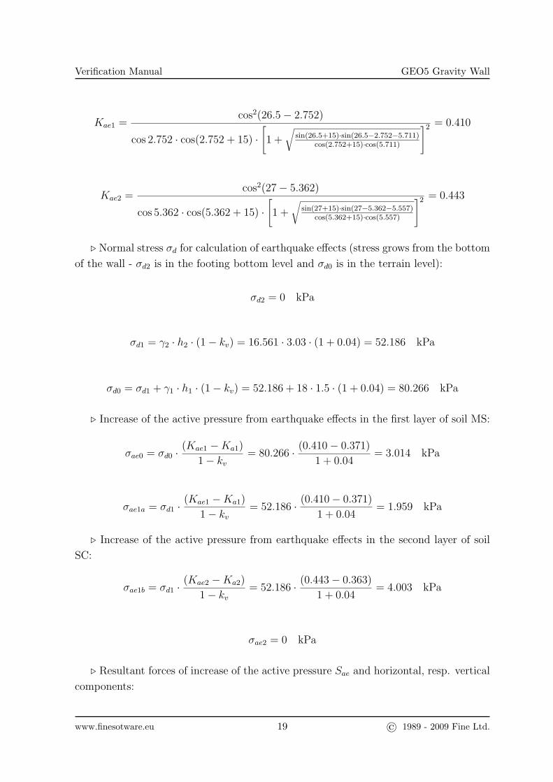
Kae1 =cos2(26.5− 2.752)
cos 2.752 · cos(2.752 + 15) ·[1 +
√sin(26.5+15)·sin(26.5−2.752−5.711)
cos(2.752+15)·cos(5.711)
]2 = 0.410
Kae2 =cos2(27− 5.362)
cos 5.362 · cos(5.362 + 15) ·[1 +
√sin(27+15)·sin(27−5.362−5.557)
cos(5.362+15)·cos(5.557)
]2 = 0.443
. Normal stress σd for calculation of earthquake effects (stress grows from the bottom
of the wall - σd2 is in the footing bottom level and σd0 is in the terrain level):
σd2 = 0 kPa
σd1 = γ2 · h2 · (1− kv) = 16.561 · 3.03 · (1 + 0.04) = 52.186 kPa
σd0 = σd1 + γ1 · h1 · (1− kv) = 52.186 + 18 · 1.5 · (1 + 0.04) = 80.266 kPa
. Increase of the active pressure from earthquake effects in the first layer of soil MS:
σae0 = σd0 ·(Kae1 −Ka1)
1− kv= 80.266 · (0.410− 0.371)
1 + 0.04= 3.014 kPa
σae1a = σd1 ·(Kae1 −Ka1)
1− kv= 52.186 · (0.410− 0.371)
1 + 0.04= 1.959 kPa
. Increase of the active pressure from earthquake effects in the second layer of soil
SC:
σae1b = σd1 ·(Kae2 −Ka2)
1− kv= 52.186 · (0.443− 0.363)
1 + 0.04= 4.003 kPa
σae2 = 0 kPa
. Resultant forces of increase of the active pressure Sae and horizontal, resp. vertical
components:
www.finesotware.eu 19 © 1989 - 2009 Fine Ltd.
Verification Manual GEO5 Gravity Wall
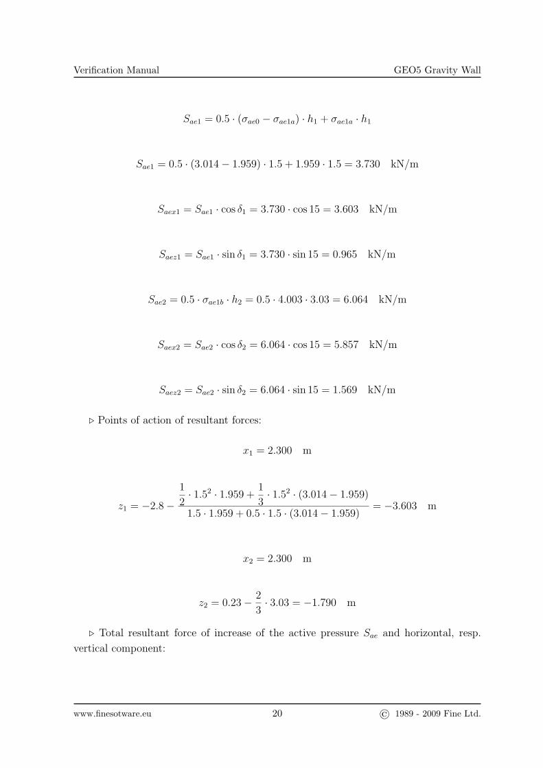
Sae1 = 0.5 · (σae0 − σae1a) · h1 + σae1a · h1
Sae1 = 0.5 · (3.014− 1.959) · 1.5 + 1.959 · 1.5 = 3.730 kN/m
Saex1 = Sae1 · cos δ1 = 3.730 · cos 15 = 3.603 kN/m
Saez1 = Sae1 · sin δ1 = 3.730 · sin 15 = 0.965 kN/m
Sae2 = 0.5 · σae1b · h2 = 0.5 · 4.003 · 3.03 = 6.064 kN/m
Saex2 = Sae2 · cos δ2 = 6.064 · cos 15 = 5.857 kN/m
Saez2 = Sae2 · sin δ2 = 6.064 · sin 15 = 1.569 kN/m
. Points of action of resultant forces:
x1 = 2.300 m
z1 = −2.8−
1
2· 1.52 · 1.959 +
1
3· 1.52 · (3.014− 1.959)
1.5 · 1.959 + 0.5 · 1.5 · (3.014− 1.959)= −3.603 m
x2 = 2.300 m
z2 = 0.23− 2
3· 3.03 = −1.790 m
. Total resultant force of increase of the active pressure Sae and horizontal, resp.
vertical component:
www.finesotware.eu 20 © 1989 - 2009 Fine Ltd.
Verification Manual GEO5 Gravity Wall
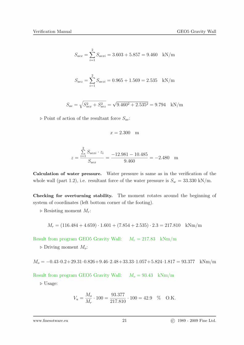
Saex =2∑i=1
Saexi = 3.603 + 5.857 = 9.460 kN/m
Saez =2∑i=1
Saezi = 0.965 + 1.569 = 2.535 kN/m
Sae =√S2aex + S2
aez =√
9.4602 + 2.5352 = 9.794 kN/m
. Point of action of the resultant force Sae:
x = 2.300 m
z =
2∑i=1
Saexi · zi
Saex=−12.981− 10.485
9.460= −2.480 m
Calculation of water pressure. Water pressure is same as in the verification of the
whole wall (part 1.2), i.e. resultant force of the water pressure is Sw = 33.330 kN/m.
Checking for overturning stability. The moment rotates around the beginning of
system of coordinates (left bottom corner of the footing).
. Resisting moment Mr:
Mr = (116.484 + 4.659) · 1.601 + (7.854 + 2.535) · 2.3 = 217.810 kNm/m
Result from program GEO5 Gravity Wall: Mr = 217.83 kNm/m
. Driving moment Mo:
Mo = −0.43·0.2+29.31·0.826+9.46·2.48+33.33·1.057+5.824·1.817 = 93.377 kNm/m
Result from program GEO5 Gravity Wall: Mo = 93.43 kNm/m
. Usage:
Vu =Mo
Mr
· 100 =93.377
217.810· 100 = 42.9 % O.K.
www.finesotware.eu 21 © 1989 - 2009 Fine Ltd.
Verification Manual GEO5 Gravity Wall
Result from program GEO5 Gravity Wall: Vu = 42.9 % O.K.
Checking for slip. Slip in the inclined footing bottom is checked. (Fig. 4).
. Total vertical and horizontal forces Fvert and Fhor:
Fvert = 116.484 + 4.659 + 7.854 + 2.535 = 131.531 kN/m
Fhor = −0.430 + 29.310 + 9.460 + 33.330 + 5.824 = 77.494 kN/m
. Normal force in the footing bottom (inclination of footing bottom αb = 5.711◦, see
Fig. 4):
N = 131.531 · cos 5.711 + 77.494 · sin 5.711 = 138.589 kN/m
. Shear reaction in the footing bottom:
T = −131.531 · sin 5.711 + 77.494 · cos 5.711 = 64.022 kN/m
. Eccentricity of the normal force (inclined width of the footing bottom d = 2.311
m):
e =d
2− Mr −Mo
N=
2.311
2− 217.810− 93.43
138.589= 0.258 m
. Maximal allowable eccentricity:
ealw =d
3=
2.311
3= 0.770 m > e = 0.258 m O.K.
. Resisting force Hr:
Hr = 138.589 · tan 27 + 8 · (2.311− 2 · 0.258) = 84.981 kN/m
Result from program GEO5 Gravity Wall: Hr = 85.07 kN/m
. Driving force Hd:
Hd = T = 64.022 kN/m
Result from program GEO5 Gravity Wall: Hd = 64.05 kN/m
www.finesotware.eu 22 © 1989 - 2009 Fine Ltd.
Verification Manual GEO5 Gravity Wall
. Usage:
Vu =Hd
Hr
· 100 =64.022
84.981· 100 = 75.3 % O.K.
Result from program GEO5 Gravity Wall: Vu = 75.3 % O.K.
1.6 Bearing capacity of the foundation soil
Bearing capacity of the foundation soil is set as Rd = 100 kPa and is compared with
stress in the inclined footing bottom.
. Usage - eccentricity:
Vu =e
ealw· 100 =
0.258
0.770· 100 = 33.5 % O.K.
Result from program GEO5 Gravity Wall: Vu = 33.1 % O.K.
. Stress in the footing bottom:
σ =N
(d− 2 · e)=
138.589
(2.311− 2 · 0.258)= 77.178 kPa
Result from program GEO5 Gravity Wall: σ = 76.72 kPa
. Usage:
Vu =σ
Rd
· 100 =77.178
100· 100 = 77.2 % O.K.
Result from program GEO5 Gravity Wall: Vu = 76.7 % O.K.
References
[1] Czech normalization institute: EN 1992-1-1, Eurocode 2: Design of concrete
structures - Part 1-1: General rules and rules for buildings. CNI, Prague, 2006
[2] Mononobe N., Matsuo, H.: On the determination of earth pressure during
earthquakes. In Proc. Of the World Engineering Conf., Vol. 9, pg. 176, 1929
[3] Okabe S.: General theory of earth pressure. Journal of the Japanese Society of
Civil Engineers, Tokyo, Japan, 1926
www.finesotware.eu 23 © 1989 - 2009 Fine Ltd.