Verification Examples - IngWare GmbH · AxisVM 13 Verification Examples 2 Linear static ......
90
Verification Examples 2015
Transcript of Verification Examples - IngWare GmbH · AxisVM 13 Verification Examples 2 Linear static ......
Verification Examples
2015
AxisVM 13 Verification Examples 2
Linear static ............................................................................................................. 3
Supported bar with concentrated loads. ....................................................................................................................... 4 Thermally loaded bar structure. .................................................................................................................................... 5 Continously supported beam with constant distributed load. ........................................................................................ 6 External prestessed beam. .......................................................................................................................................... 9 Periodically supported infinite membrane wall with constant distributed load. ........................................................... 11 Clamped beam examination with plane stress elements. ........................................................................................... 13 Clamped thin square plate. ......................................................................................................................................... 16 Plate with fixed support and constant distributed load. ............................................................................................... 18 Annular plate. ............................................................................................................................................................. 19 All edges simply supported plate with partial distributed load. ................................................................................... 21 Clamped plate with linear distributed load. ................................................................................................................. 23 Hemisphere displacement. ......................................................................................................................................... 25
Nonlinear static ...................................................................................................... 27 3D beam structure. ..................................................................................................................................................... 28 Plate with fixed end and bending moment. ................................................................................................................. 30
Dynamic ................................................................................................................. 33 Deep simply supported beam. .................................................................................................................................... 34 Clamped thin rhombic plate. ....................................................................................................................................... 37 Cantilevered thin square plate. ................................................................................................................................... 39 Cantilevered tapered membrane. ............................................................................................................................... 42 Flat grillages. .............................................................................................................................................................. 45
Stability .................................................................................................................. 49 Simply supported beam. ............................................................................................................................................. 50 Simply supported beam. ............................................................................................................................................. 52
Design ................................................................................................................... 53 N-M interaction curve of cross-section EC2, EN 1992-1-1:2004. ............................................................................... 54 RC beam deflection according to EC2, EN 1992-1-1:2004. ....................................................................................... 55 Required steel reinforcement of RC plate according to EC2, EN 1992-1-1:2004……………………………...………..57 Interaction check of beam under biaxial bending EC3, EN 1993-1-1:2009…………………………...………………….59 Interaction check of beam under normal force, bending and shear force EC3, EN 1993-1-1:2009…………………...61 Buckling resistance of simply supported I beam EC3, EN 1993-1-1:2009…….…………………………………………63 Buckling resistance of simply supported T beam EC3, EN 1993-1-1:2009……………………………………………....65 Buckling of a hollow cross-section beam EC3, EN 1993-1-1:2009…………………………………………………….….67 Lateral torsional buckling of a beam EC3, EN 1993-1-1:2009……………………………………………………………..71 Interaction check of beam in section class 4. EC3, EN 1993-1-1:2009, EN 1993-1-5:2012………………………...…77 Earth-quake design using response-spectrum method. ……………………………………………………..………80

AxisVM 13 Verification Examples 3
Linear static
AxisVM 13 Verification Examples 4 Software Release Number: R1 Date: 17. 08. 2015 Tested by: InterCAD Page number: File name: beam1.axs
Thema
Supported bar with concentrated loads.
Analysis Type
Linear analysis.
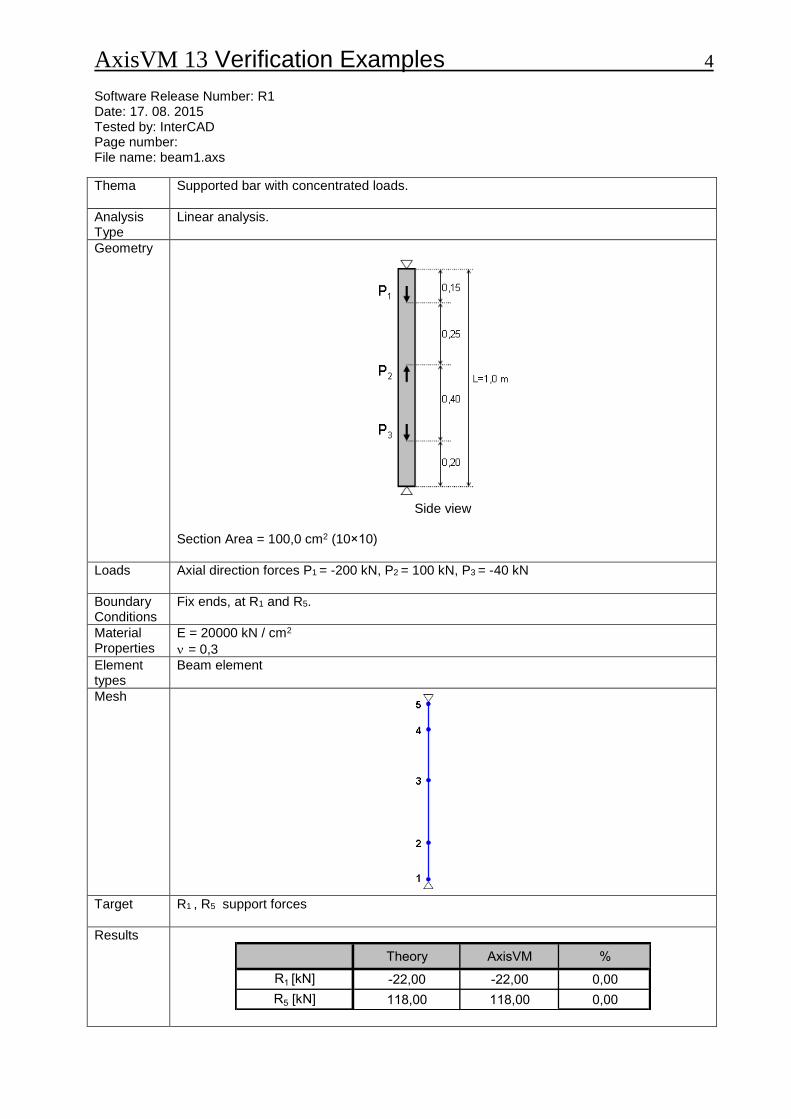
Geometry
Side view
Section Area = 100,0 cm2 (10×10)
Loads
Axial direction forces P1 = -200 kN, P2 = 100 kN, P3 = -40 kN
Boundary Conditions
Fix ends, at R1 and R5.
Material Properties
E = 20000 kN / cm2
= 0,3
Element types
Beam element
Mesh
Target
R1 , R5 support forces
Results
Theory AxisVM %
R1 [kN] -22,00 -22,00 0,00
R5 [kN] 118,00 118,00 0,00
AxisVM 13 Verification Examples 5 Software Release Number: R3 Date: 17. 08. 2015. Tested by: InterCAD Page number: File name: beam2.axs
Thema
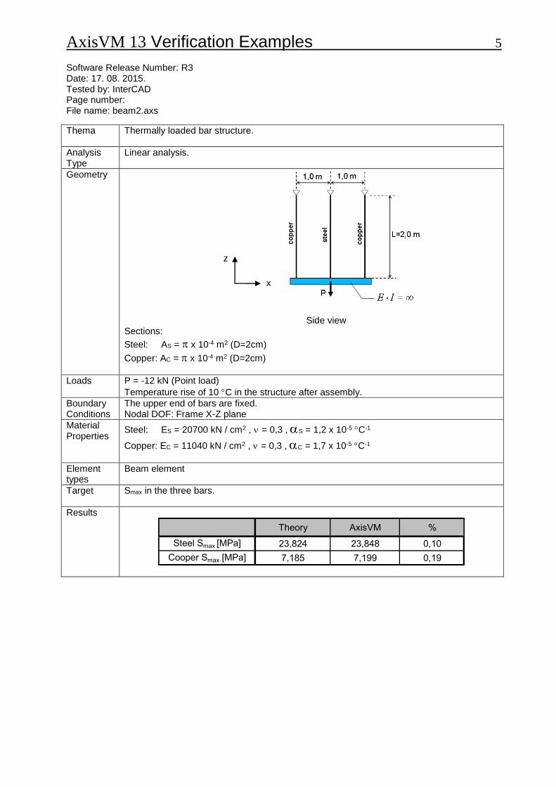
Thermally loaded bar structure.
Analysis Type
Linear analysis.
Geometry
Side view Sections:
Steel: AS = x 10-4 m2 (D=2cm)
Copper: AC = x 10-4 m2 (D=2cm)
Loads
P = -12 kN (Point load)
Temperature rise of 10 C in the structure after assembly.
Boundary Conditions
The upper end of bars are fixed. Nodal DOF: Frame X-Z plane
Material Properties
Steel: ES = 20700 kN / cm2 , = 0,3 , S = 1,2 x 10⁻⁵ C-1
Copper: EC = 11040 kN / cm2 , = 0,3 , C = 1,7 x 10⁻⁵ C-1
Element types
Beam element
Target
Smax in the three bars.
Results
Theory AxisVM %
Steel Smax [MPa] 23,824 23,848 0,10
Cooper Smax [MPa] 7,185 7,199 0,19
z
x
AxisVM 13 Verification Examples 6 Software Release Number: R3 Date: 17. 08. 2015. Tested by: InterCAD Page number: File name: beam3.axs
Thema
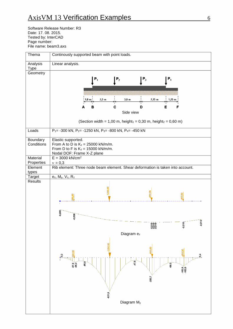
Continously supported beam with point loads.
Analysis Type
Linear analysis.
Geometry
Side view
(Section width = 1,00 m, height1 = 0,30 m, height2 = 0,60 m)
Loads
P1= -300 kN, P2= -1250 kN, P3= -800 kN, P4= -450 kN
Boundary Conditions
Elastic supported. From A to D is Kz = 25000 kN/m/m. From D to F is Kz = 15000 kN/m/m. Nodal DOF: Frame X-Z plane
Material Properties
E = 3000 kN/cm2
= 0,3
Element types
Rib element: Three node beam element. Shear deformation is taken into account.
Target ez, My, Vz, Rz
Results
Diagram ez
Diagram My
AxisVM 13 Verification Examples 7
Results
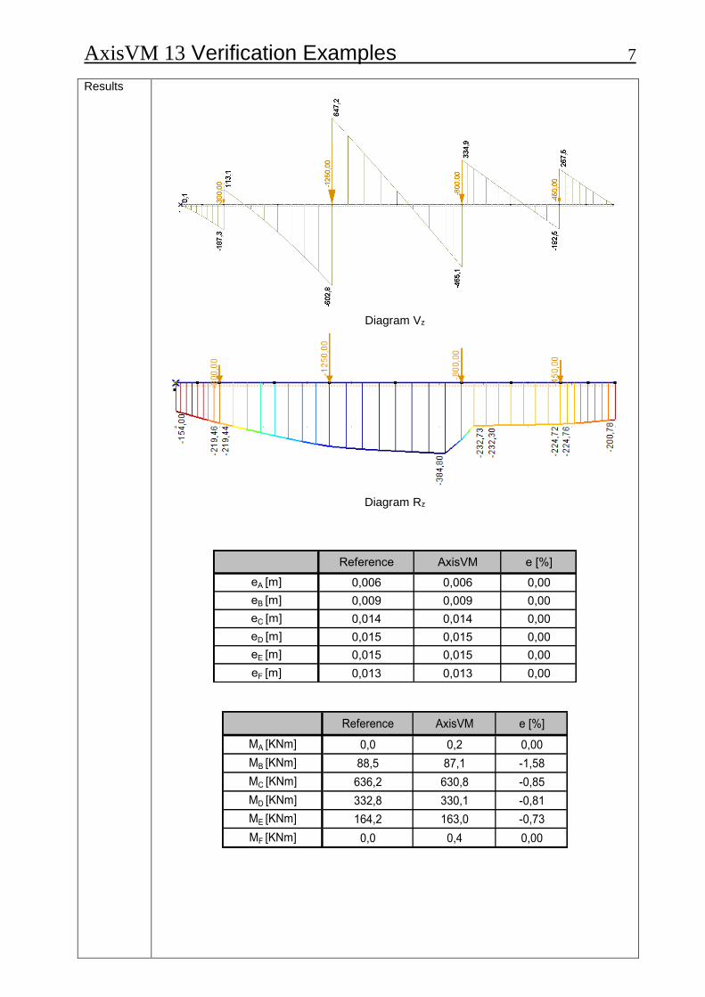
Diagram Vz
Diagram Rz
Reference AxisVM e [%]
eA [m] 0,006 0,006 0,00
eB [m] 0,009 0,009 0,00
eC [m] 0,014 0,014 0,00
eD [m] 0,015 0,015 0,00
eE [m] 0,015 0,015 0,00
eF [m] 0,013 0,013 0,00
Reference AxisVM e [%]
MA [KNm] 0,0 0,2 0,00
MB [KNm] 88,5 87,1 -1,58
MC [KNm] 636,2 630,8 -0,85
MD [KNm] 332,8 330,1 -0,81
ME [KNm] 164,2 163,0 -0,73
MF [KNm] 0,0 0,4 0,00
AxisVM 13 Verification Examples 8
Results
Reference AxisVM e [%]
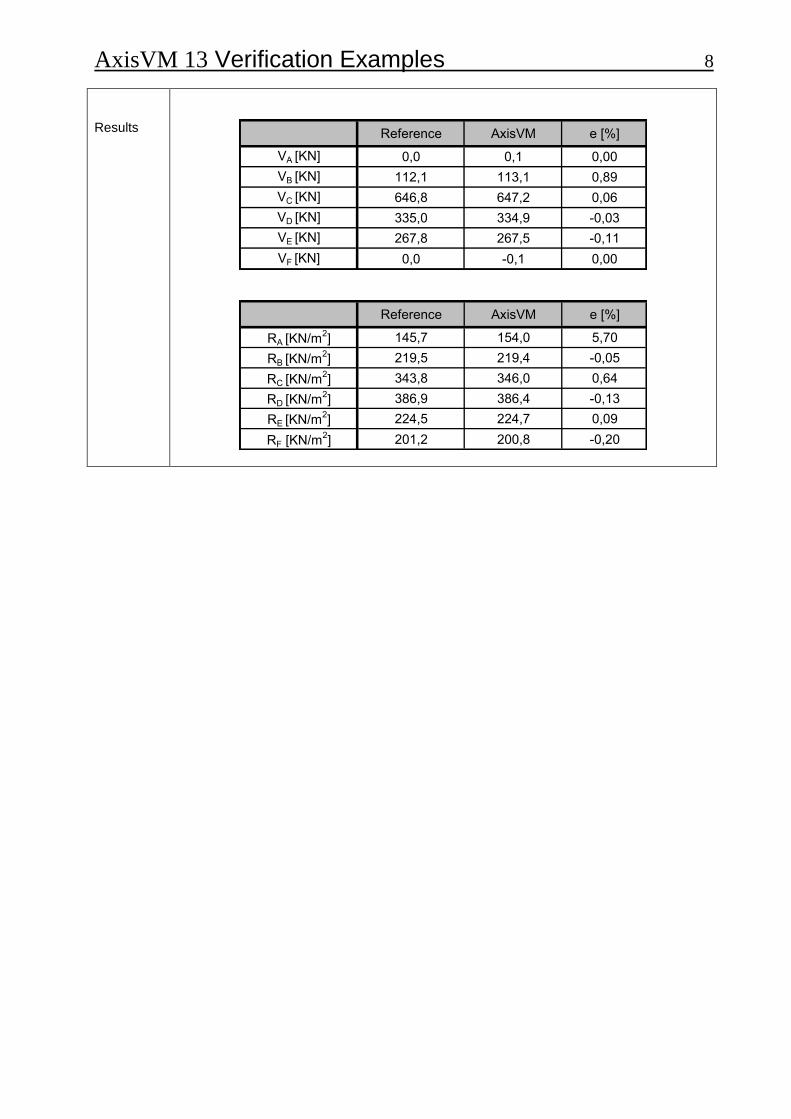
VA [KN] 0,0 0,1 0,00
VB [KN] 112,1 113,1 0,89
VC [KN] 646,8 647,2 0,06
VD [KN] 335,0 334,9 -0,03
VE [KN] 267,8 267,5 -0,11
VF [KN] 0,0 -0,1 0,00
Reference AxisVM e [%]
RA [KN/m2] 145,7 154,0 5,70
RB [KN/m2] 219,5 219,4 -0,05
RC [KN/m2] 343,8 346,0 0,64
RD [KN/m2] 386,9 386,4 -0,13
RE [KN/m2] 224,5 224,7 0,09
RF [KN/m2] 201,2 200,8 -0,20
AxisVM 13 Verification Examples 9 Software Release Number: R3 Date: 17. 08. 2015. Tested by: InterCAD Page number: File name: beam4.axs
Thema
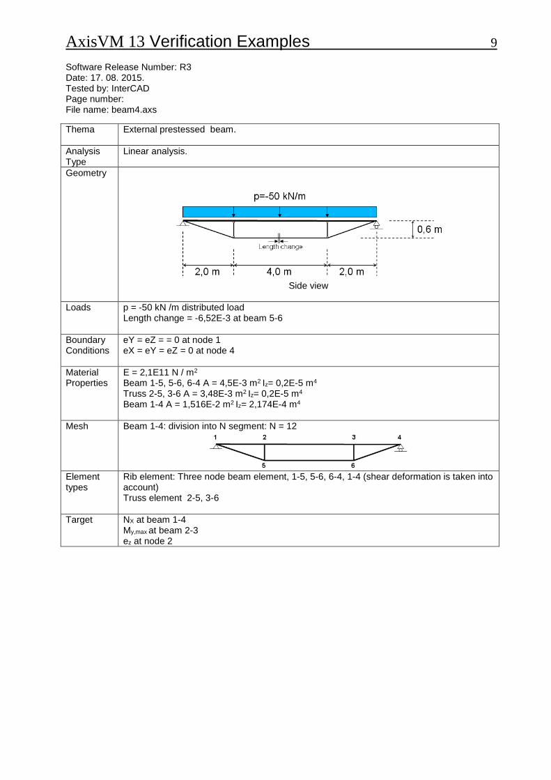
External prestessed beam.
Analysis Type
Linear analysis.
Geometry
Side view
Loads
p = -50 kN /m distributed load Length change = -6,52E-3 at beam 5-6
Boundary Conditions
eY = eZ = = 0 at node 1 eX = eY = eZ = 0 at node 4
Material Properties
E = 2,1E11 N / m2 Beam 1-5, 5-6, 6-4 A = 4,5E-3 m2 Iz= 0,2E-5 m4 Truss 2-5, 3-6 A = 3,48E-3 m2 Iz= 0,2E-5 m4 Beam 1-4 A = 1,516E-2 m2 Iz= 2,174E-4 m4
Mesh Beam 1-4: division into N segment: N = 12
Element types
Rib element: Three node beam element, 1-5, 5-6, 6-4, 1-4 (shear deformation is taken into account) Truss element 2-5, 3-6
Target
NX at beam 1-4 My,max at beam 2-3 ez at node 2
AxisVM 13 Verification Examples 10
Results
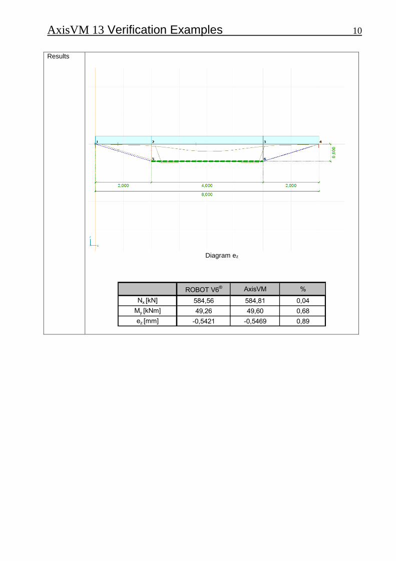
Diagram ez
ROBOT V6® AxisVM %
Nx [kN] 584,56 584,81 0,04
My [kNm] 49,26 49,60 0,68
ez [mm] -0,5421 -0,5469 0,89
AxisVM 13 Verification Examples 11 Software Release Number: R3 Date: 17. 08. 2015. Tested by: InterCAD Page number: File name: plane1.axs
Thema
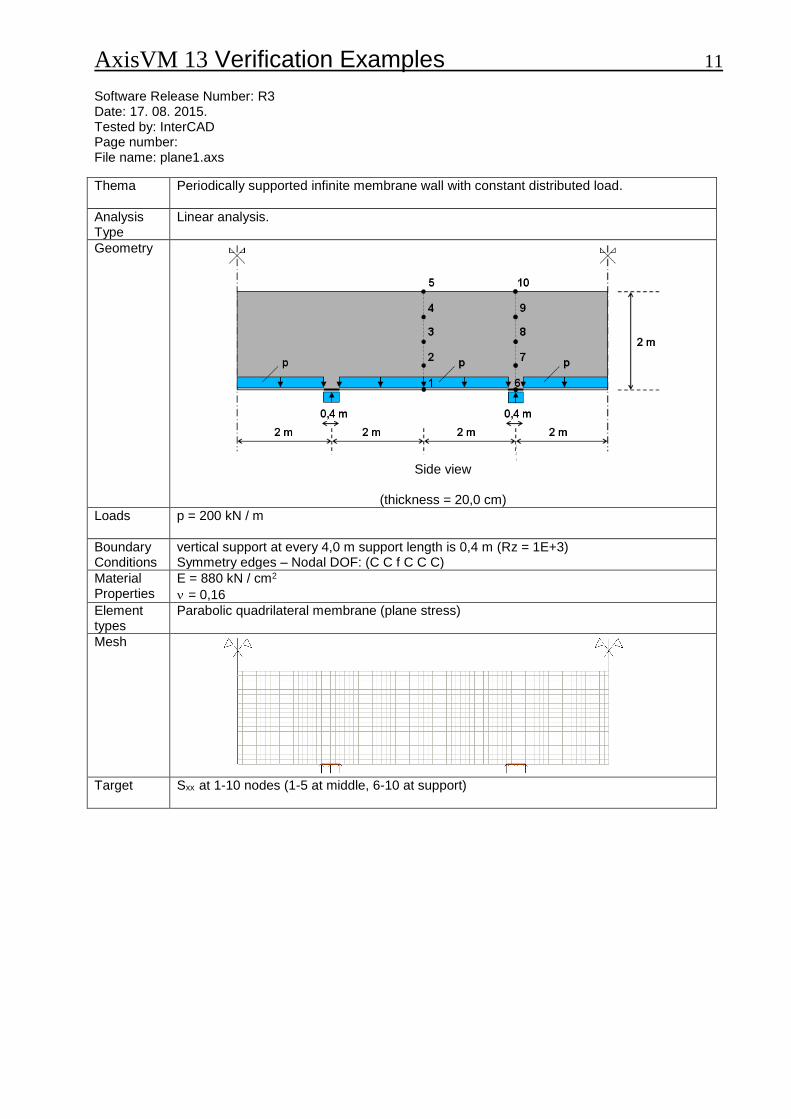
Periodically supported infinite membrane wall with constant distributed load.
Analysis Type
Linear analysis.
Geometry
Side view
(thickness = 20,0 cm)
Loads
p = 200 kN / m
Boundary Conditions
vertical support at every 4,0 m support length is 0,4 m (Rz = 1E+3) Symmetry edges – Nodal DOF: (C C f C C C)
Material Properties
E = 880 kN / cm2
= 0,16
Element types
Parabolic quadrilateral membrane (plane stress)
Mesh
Target
Sxx at 1-10 nodes (1-5 at middle, 6-10 at support)
AxisVM 13 Verification Examples 12
Results
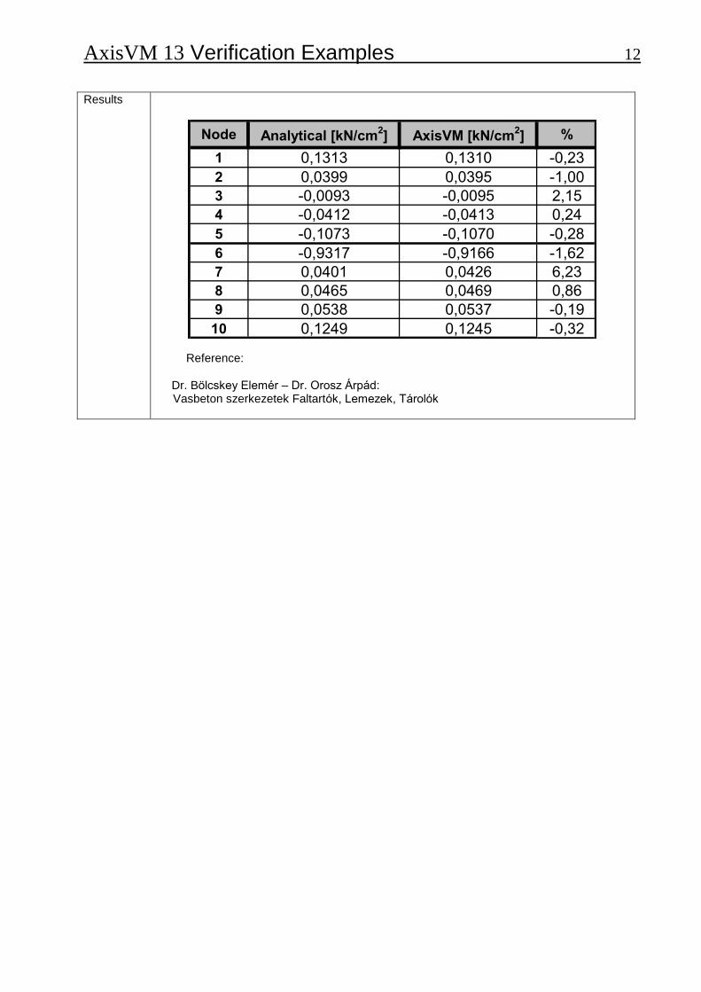
Node Analytical [kN/cm2] AxisVM [kN/cm
2] %
1 0,1313 0,1310 -0,23
2 0,0399 0,0395 -1,00
3 -0,0093 -0,0095 2,15
4 -0,0412 -0,0413 0,24
5 -0,1073 -0,1070 -0,28
6 -0,9317 -0,9166 -1,62
7 0,0401 0,0426 6,23
8 0,0465 0,0469 0,86
9 0,0538 0,0537 -0,19
10 0,1249 0,1245 -0,32
Reference: Dr. Bölcskey Elemér – Dr. Orosz Árpád: Vasbeton szerkezetek Faltartók, Lemezek, Tárolók

AxisVM 13 Verification Examples 13 Software Release Number: R3 Date: 17. 08. 2015. Tested by: InterCAD Page number: File name: plane2.axs
Thema
Clamped beam examination with plane stress elements.
Analysis Type
Linear analysis.
Geometry
Side view
Loads
p = -25 kN/m
Boundary Conditions
Both ends built-in. Line support component stiffness: 1E+10. Symmetry edge – Nodal DOF: (C C f C C C)
Material Properties
E = 880 kN / cm2
= 0
Element types
Parabolic quadrilateral membrane (plane stress)
Mesh
Side view

AxisVM 13 Verification Examples 14
Target
xy, max at section C Results
Diagram xy
Diagram xy at section C

AxisVM 13 Verification Examples 15
2
'
4
3'
/5,78700260416,025,0
0078125,0625,65
00260416,0
25,0
0078125,0
)(625,65
mkNIb
SV
mI
mb
mS
theorybeamfromkNV
y
y
xy
y
y
AxisVM result xy = 786,8 kN / m2
Difference = -0,09 %
AxisVM result kNnV xy 33,65
Difference = -0,45 %

AxisVM 13 Verification Examples 16 Software Release Number: R3 Date: 17. 08. 2015. Tested by: InterCAD Page number: File name: plate1.axs
Thema
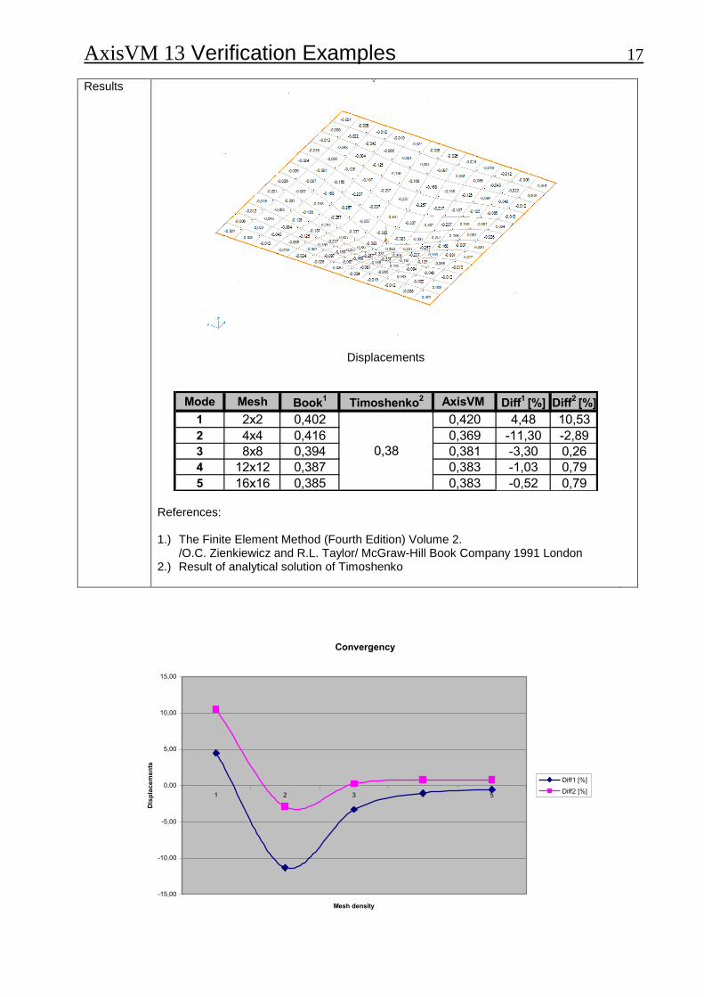
Clamped thin square plate.
Analysis Type
Linear analysis.
Geometry
Top view
(thickness = 5,0 cm)
Loads
P = -10 kN (at the middle of the plate)
Boundary Conditions
eX = ez = eZ = fiX = fiY = fiZ = 0 along all edges Nodal DOF: Plate in X-Y plane
Material Properties
E = 20000 kN / cm2
= 0,3
Element types
Plate element (Parabolic quadrilateral, heterosis)
Mesh
Target
Displacement of middle of the plate
AxisVM 13 Verification Examples 17
Results
Displacements
Mode Mesh Book1
Timoshenko2 AxisVM Diff
1 [%] Diff
2 [%]
1 2x2 0,402 0,420 4,48 10,53
2 4x4 0,416 0,369 -11,30 -2,89
3 8x8 0,394 0,381 -3,30 0,26
4 12x12 0,387 0,383 -1,03 0,79
5 16x16 0,385 0,383 -0,52 0,79
0,38
References: 1.) The Finite Element Method (Fourth Edition) Volume 2.
/O.C. Zienkiewicz and R.L. Taylor/ McGraw-Hill Book Company 1991 London 2.) Result of analytical solution of Timoshenko
Convergency
-15,00
-10,00
-5,00
0,00
5,00
10,00
15,00
1 2 3 4 5
Mesh density
Dis
pla
ce
me
nts
Diff1 [%]
Diff2 [%]
AxisVM 13 Verification Examples 18 Software Release Number: R3 Date: 17. 08. 2015. Tested by: InterCAD Page number: File name: plate2_1.axs
Thema
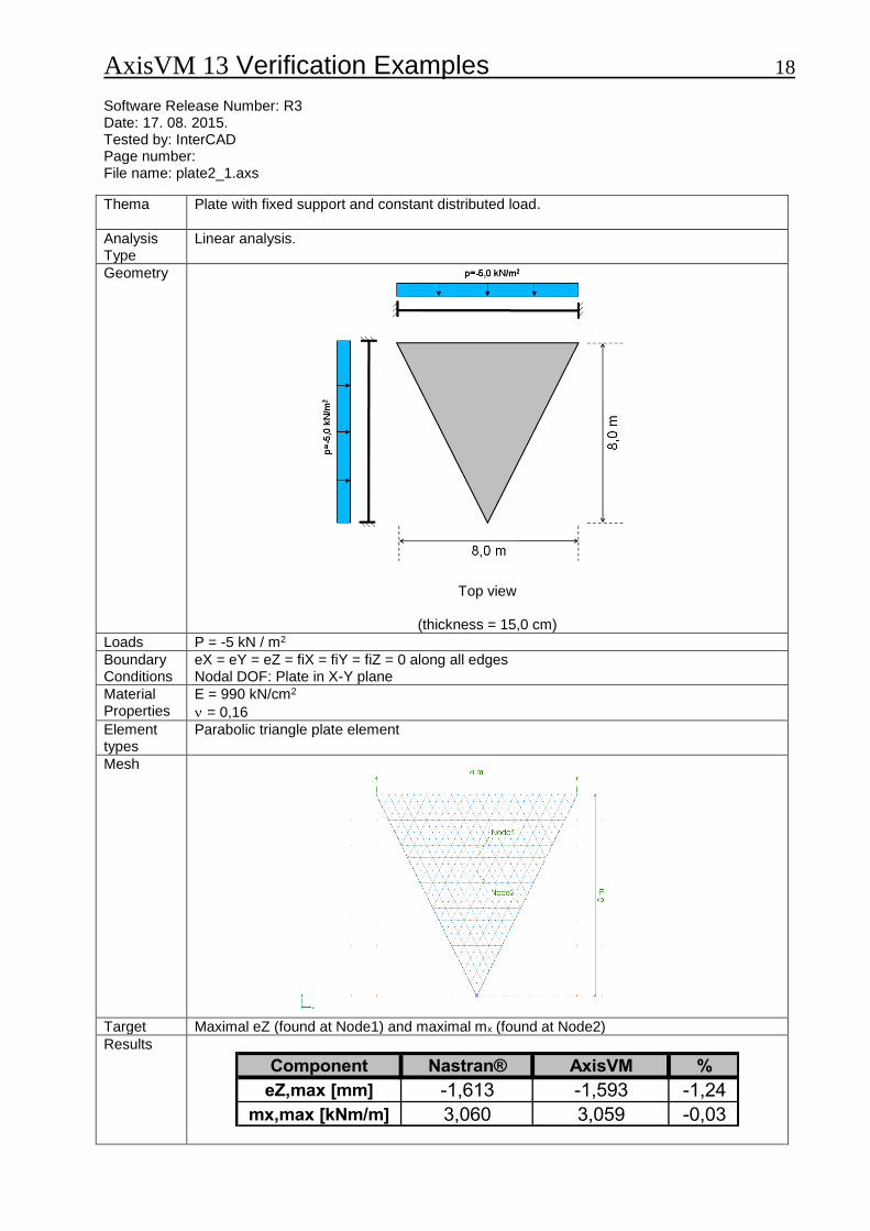
Plate with fixed support and constant distributed load.
Analysis Type
Linear analysis.
Geometry
Top view
(thickness = 15,0 cm)
Loads P = -5 kN / m2
Boundary Conditions
eX = eY = eZ = fiX = fiY = fiZ = 0 along all edges Nodal DOF: Plate in X-Y plane
Material Properties
E = 990 kN/cm2
= 0,16
Element types
Parabolic triangle plate element
Mesh
Target Maximal eZ (found at Node1) and maximal mx (found at Node2)
Results
Component Nastran® AxisVM %
eZ,max [mm] -1,613 -1,593 -1,24
mx,max [kNm/m] 3,060 3,059 -0,03

AxisVM 13 Verification Examples 19 Software Release Number: R3 Date: 17. 08. 2015. Tested by: InterCAD Page number: File name: plate3.axs
Thema
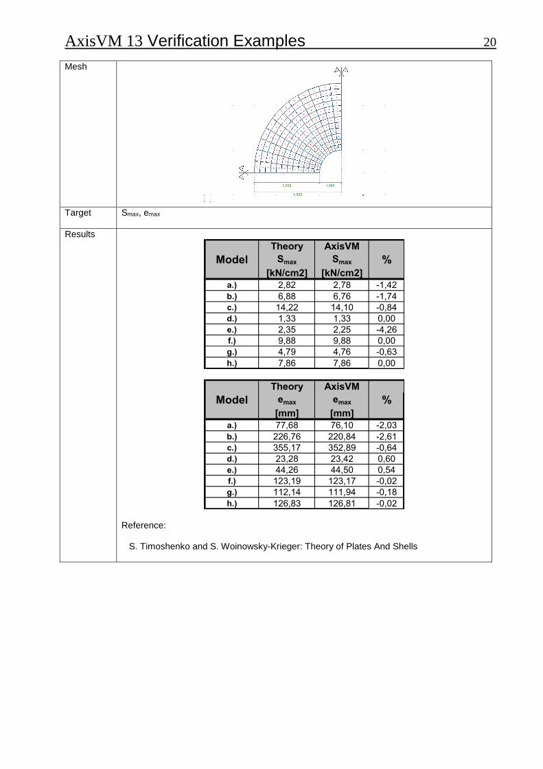
Annular plate.
Analysis Type
Linear analysis.
Geometry
Top view
(thickness = 22,0 cm)
Loads
Edge load: Q = 100 kN / m
Distributed load: q = 100 kN / m2
Boundary Conditions
Nodal DOF: Plate in X-Y plane
Material Properties
E = 880 kN / cm2
= 0,3
Element types
Plate element (parabolic quadrilateral, heterosis)
AxisVM 13 Verification Examples 20
Mesh
Target Smax, emax
Results
Theory AxisVM
Model Smax Smax %[kN/cm2] [kN/cm2]
a.) 2,82 2,78 -1,42
b.) 6,88 6,76 -1,74
c.) 14,22 14,10 -0,84
d.) 1,33 1,33 0,00
e.) 2,35 2,25 -4,26
f.) 9,88 9,88 0,00
g.) 4,79 4,76 -0,63
h.) 7,86 7,86 0,00
Theory AxisVM
Model emax emax %[mm] [mm]
a.) 77,68 76,10 -2,03
b.) 226,76 220,84 -2,61
c.) 355,17 352,89 -0,64
d.) 23,28 23,42 0,60
e.) 44,26 44,50 0,54
f.) 123,19 123,17 -0,02
g.) 112,14 111,94 -0,18
h.) 126,83 126,81 -0,02 Reference: S. Timoshenko and S. Woinowsky-Krieger: Theory of Plates And Shells

AxisVM 13 Verification Examples 21 Software Release Number: R3 Date: 17. 08. 2015. Tested by: InterCAD Page number: File name: plate4.axs
Thema
All edges simply supported plate with partial distributed load.
Analysis Type
Linear analysis.
Geometry
Top view
(thickness = 22,0 cm)
Loads
Distributed load: q = -10 kN / m2 (middle of the plate at 2,0 x 2,0 m area)
Boundary Conditions
a.) eX = eY = eZ = 0 along all edges (soft support)
b.) eX = eY = eZ = 0 along all edges = 0 perpendicular the edges (hard support) Nodal DOF: Plate in X-Y plane
Material Properties
E = 880 kN / cm2
= 0,3
Element types
Plate element (Heterosis)
Mesh

AxisVM 13 Verification Examples 22
Target
mx, max, my, max
Results a.)
Moment Theory AxisVM %
mx, max [kNm/m] 7,24 7,34 1,38
my, max [kNm/m] 5,32 5,39 1,32
b.)
Moment Theory AxisVM %
mx, max [kNm/m] 7,24 7,28 0,55
my, max [kNm/m] 5,32 5,35 0,56
Reference: S. Timoshenko and S. Woinowsky-Krieger: Theory of Plates And Shells
AxisVM 13 Verification Examples 23 Software Release Number: R3 Date: 17. 08. 2015. Tested by: InterCAD Page number: File name: plate5.axs
Thema
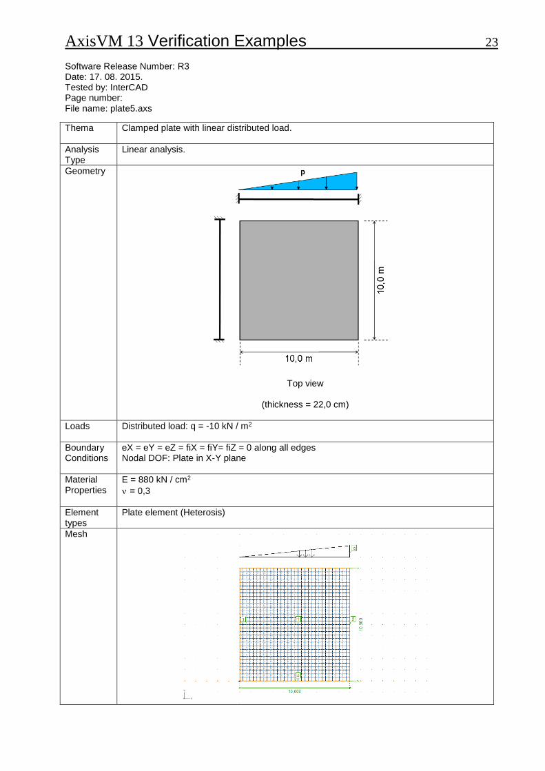
Clamped plate with linear distributed load.
Analysis Type
Linear analysis.
Geometry
Top view
(thickness = 22,0 cm)
Loads
Distributed load: q = -10 kN / m2
Boundary Conditions
eX = eY = eZ = fiX = fiY= fiZ = 0 along all edges Nodal DOF: Plate in X-Y plane
Material Properties
E = 880 kN / cm2
= 0,3
Element types
Plate element (Heterosis)
Mesh
AxisVM 13 Verification Examples 24
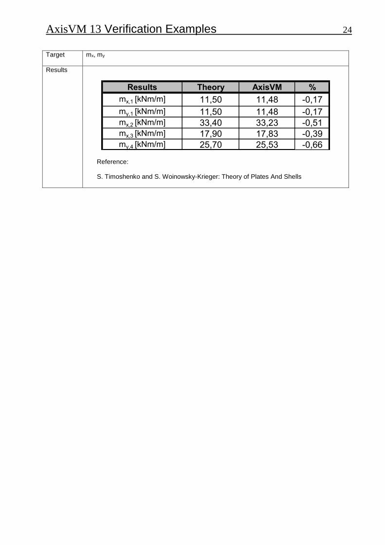
Target
mx, my
Results
Results Theory AxisVM %
mx,1 [kNm/m] 11,50 11,48 -0,17
my,1 [kNm/m] 11,50 11,48 -0,17mx,2 [kNm/m] 33,40 33,23 -0,51mx,3 [kNm/m] 17,90 17,83 -0,39my,4 [kNm/m] 25,70 25,53 -0,66
Reference: S. Timoshenko and S. Woinowsky-Krieger: Theory of Plates And Shells

AxisVM 13 Verification Examples 25 Software Release Number: R3 Date: 17. 08. 2015. Tested by: InterCAD Page number: File name: hemisphere.axs
Thema
Hemisphere displacement.
Analysis Type
Linear analysis.
Geometry
Hemisphere (Axonometric view)
t = 0,04 m
Loads
Point load P = 2,0 kN
AxisVM 13 Verification Examples 26
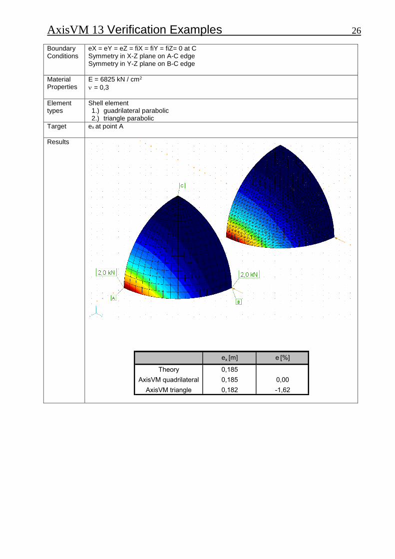
Boundary Conditions
eX = eY = eZ = fiX = fiY = fiZ= 0 at C Symmetry in X-Z plane on A-C edge Symmetry in Y-Z plane on B-C edge
Material Properties
E = 6825 kN / cm2
= 0,3
Element types
Shell element 1.) guadrilateral parabolic 2.) triangle parabolic
Target
ex at point A
Results
ex [m] e [%]
Theory 0,185
AxisVM quadrilateral 0,185 0,00
AxisVM triangle 0,182 -1,62
AxisVM 13 Verification Examples 27
Nonlinear static
AxisVM 13 Verification Examples 28 Software Release Number: R3 Date: 17. 08. 2015. Tested by: InterCAD Page number: File name: nonlin1.axs
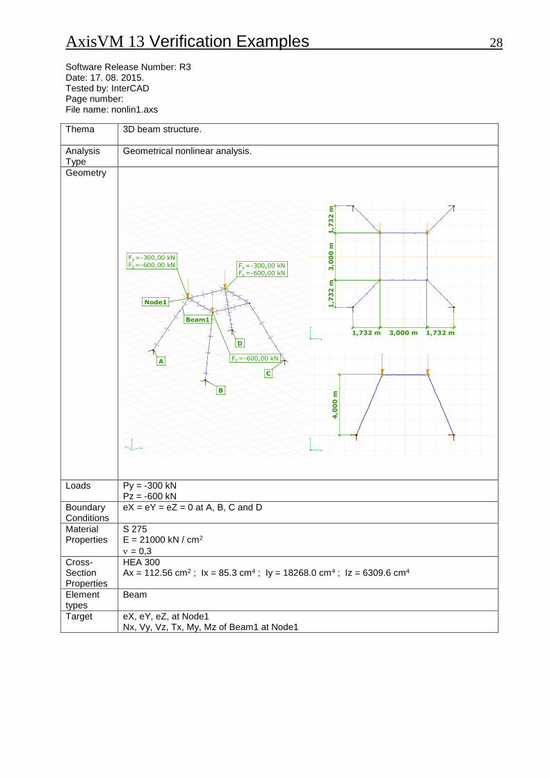
Thema
3D beam structure.
Analysis Type
Geometrical nonlinear analysis.
Geometry
Fz=-600,00 kN
Fy=-300,00 kN
Fz=-600,00 kN
Fy=-300,00 kN
Fz=-600,00 kN
Node1
Beam1
A
B
C
D
Fz=-600,00 kN
Fy=-300,00 kN
Fz=-600,00 kN
Fy=-300,00 kN
Fz=-600,00 kN
Node1
Beam1
A
B
C
D
XY
Z
3,000 m1
,73
2 m
1,732 m 1,732 m3
,00
0 m
1,7
32
m
X
Y
4,0
00
m
X
Z
Loads
Py = -300 kN Pz = -600 kN
Boundary Conditions
eX = eY = eZ = 0 at A, B, C and D
Material Properties
S 275 E = 21000 kN / cm2
= 0,3
Cross- Section Properties
HEA 300 Ax = 112.56 cm2 ; Ix = 85.3 cm4 ; Iy = 18268.0 cm4 ; Iz = 6309.6 cm4
Element types
Beam
Target
eX, eY, eZ, at Node1 Nx, Vy, Vz, Tx, My, Mz of Beam1 at Node1

AxisVM 13 Verification Examples 29
Results
Comparison with the results obtained using Nastran V4
Component Nastran® AxisVM %
eX [mm] 17,898 17,881 -0,09
eY [mm] -75,702 -75,663 -0,05
eZ [mm] -42,623 -42,597 -0,06
Nx [kN] -283,15 -283,25 0,04
Vy [kN] -28,09 -28,10 0,04
Vx [kN] -106,57 -106,48 -0,08
Tx [kNm] -4,57 -4,57 0,00
My [kNm] -519,00 -518,74 -0,05
Mz [kNm] 148,94 148,91 -0,02
AxisVM 13 Verification Examples 30 Software Release Number: R3 Date: 17. 08. 2015. Tested by: InterCAD Page number: File name: nonlin2.axs
Thema
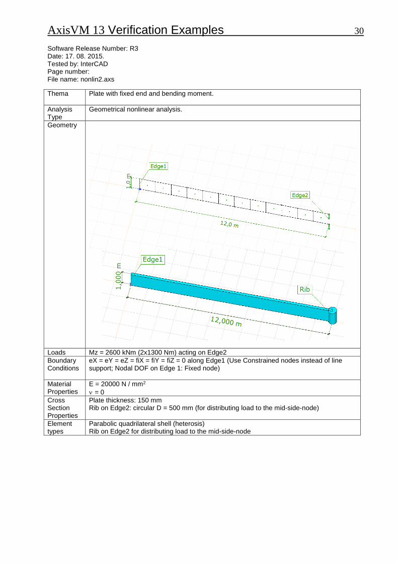
Plate with fixed end and bending moment.
Analysis Type
Geometrical nonlinear analysis.
Geometry
Loads Mz = 2600 kNm (2x1300 Nm) acting on Edge2
Boundary Conditions
eX = eY = eZ = fiX = fiY = fiZ = 0 along Edge1 (Use Constrained nodes instead of line support; Nodal DOF on Edge 1: Fixed node)
Material Properties
E = 20000 N / mm2
= 0
Cross Section Properties
Plate thickness: 150 mm Rib on Edge2: circular D = 500 mm (for distributing load to the mid-side-node)
Element types
Parabolic quadrilateral shell (heterosis) Rib on Edge2 for distributing load to the mid-side-node
AxisVM 13 Verification Examples 31
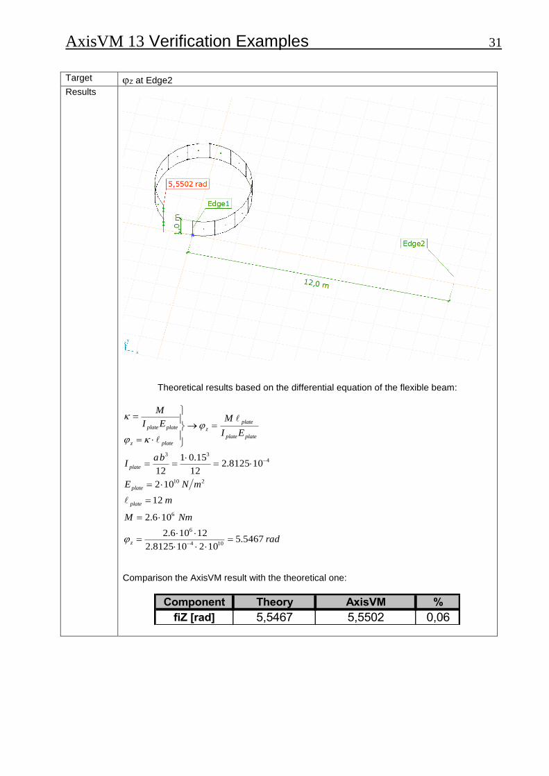
Target Z at Edge2
Results
Theoretical results based on the differential equation of the flexible beam:
rad
NmM
m
mNE
baI
EI
MEI
M
z
plate
plate
plate
plateplate
plate
z
platez
plateplate
5467.5102108125.2
12106.2
106.2
12
102
108125.212
15.01
12
104
6
6
210
433
Comparison the AxisVM result with the theoretical one:
Component Theory AxisVM %
fiZ [rad] 5,5467 5,5502 0,06

AxisVM 13 Verification Examples 32
BLANK
AxisVM 13 Verification Examples 33
Dynamic
AxisVM 13 Verification Examples 34 Software Release Number: R3 Date: 17. 08. 2015. Tested by: InterCAD Page number: File name: dynam1.axs
Thema
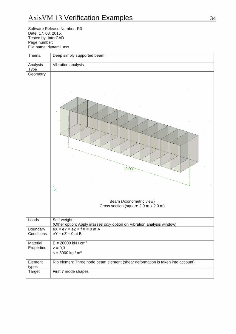
Deep simply supported beam.
Analysis Type
Vibration analysis.
Geometry
Beam (Axonometric view)
Cross section (square 2,0 m x 2,0 m)
Loads
Self-weight (Other option: Apply Masses only option on Vibration analysis window)
Boundary Conditions
eX = eY = eZ = fiX = 0 at A eY = eZ = 0 at B
Material Properties
E = 20000 kN / cm2
= 0,3
= 8000 kg / m3
Element types
Rib elemen: Three node beam element (shear deformation is taken into account)
Target
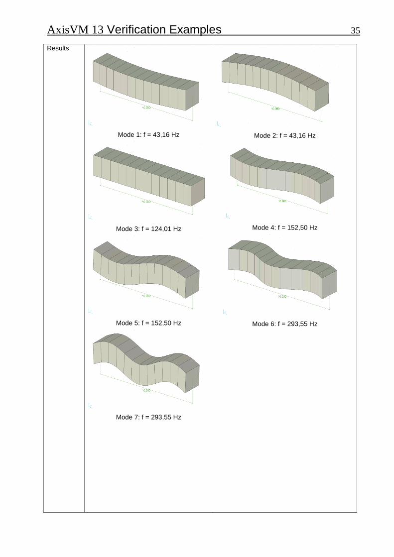
First 7 mode shapes
AxisVM 13 Verification Examples 35
Results
Mode 1: f = 43,16 Hz
Mode 3: f = 124,01 Hz
Mode 5: f = 152,50 Hz
Mode 7: f = 293,55 Hz
Mode 2: f = 43,16 Hz
Mode 4: f = 152,50 Hz
Mode 6: f = 293,55 Hz
AxisVM 13 Verification Examples 36
Results
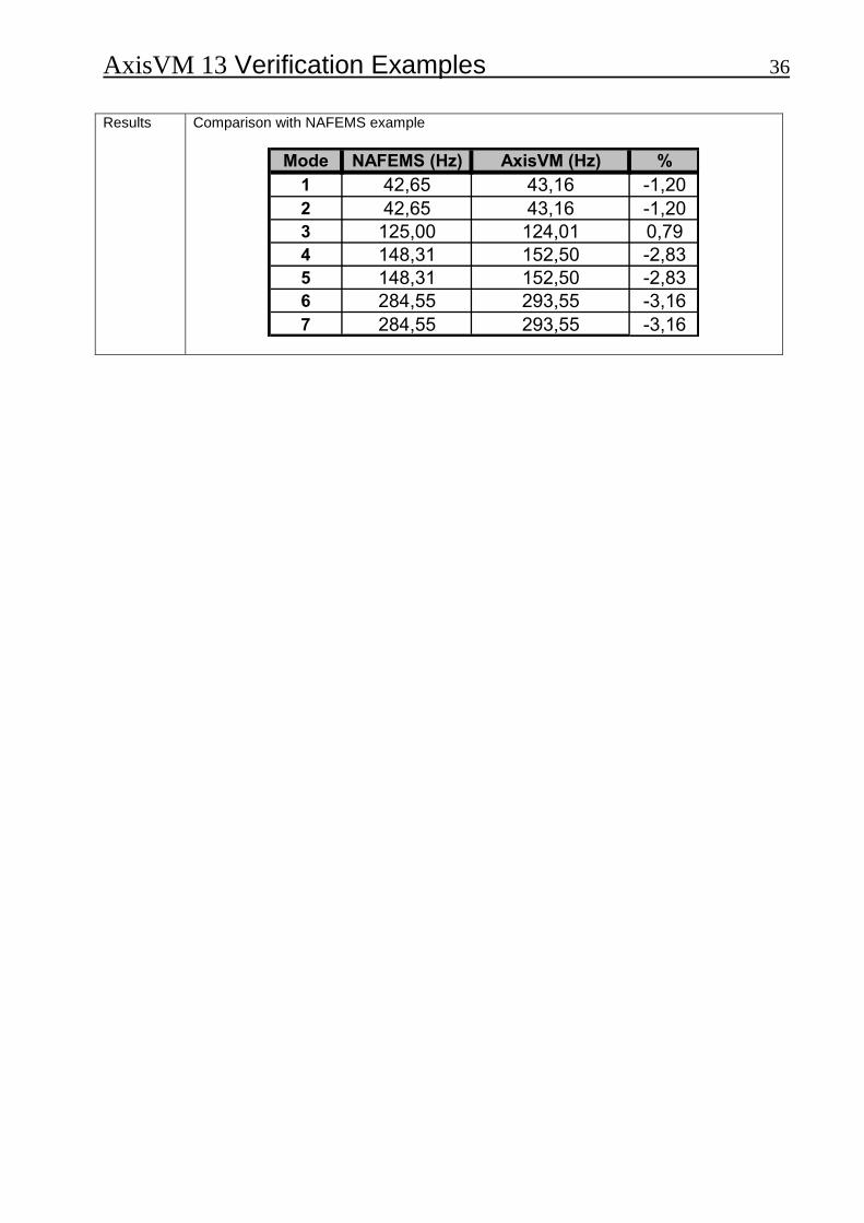
Comparison with NAFEMS example
Mode NAFEMS (Hz) AxisVM (Hz) %
1 42,65 43,16 -1,20
2 42,65 43,16 -1,20
3 125,00 124,01 0,79
4 148,31 152,50 -2,83
5 148,31 152,50 -2,83
6 284,55 293,55 -3,16
7 284,55 293,55 -3,16
AxisVM 13 Verification Examples 37 Software Release Number: R3 Date: 17. 08. 2015. Tested by: InterCAD Page number: File name: dynam2.axs
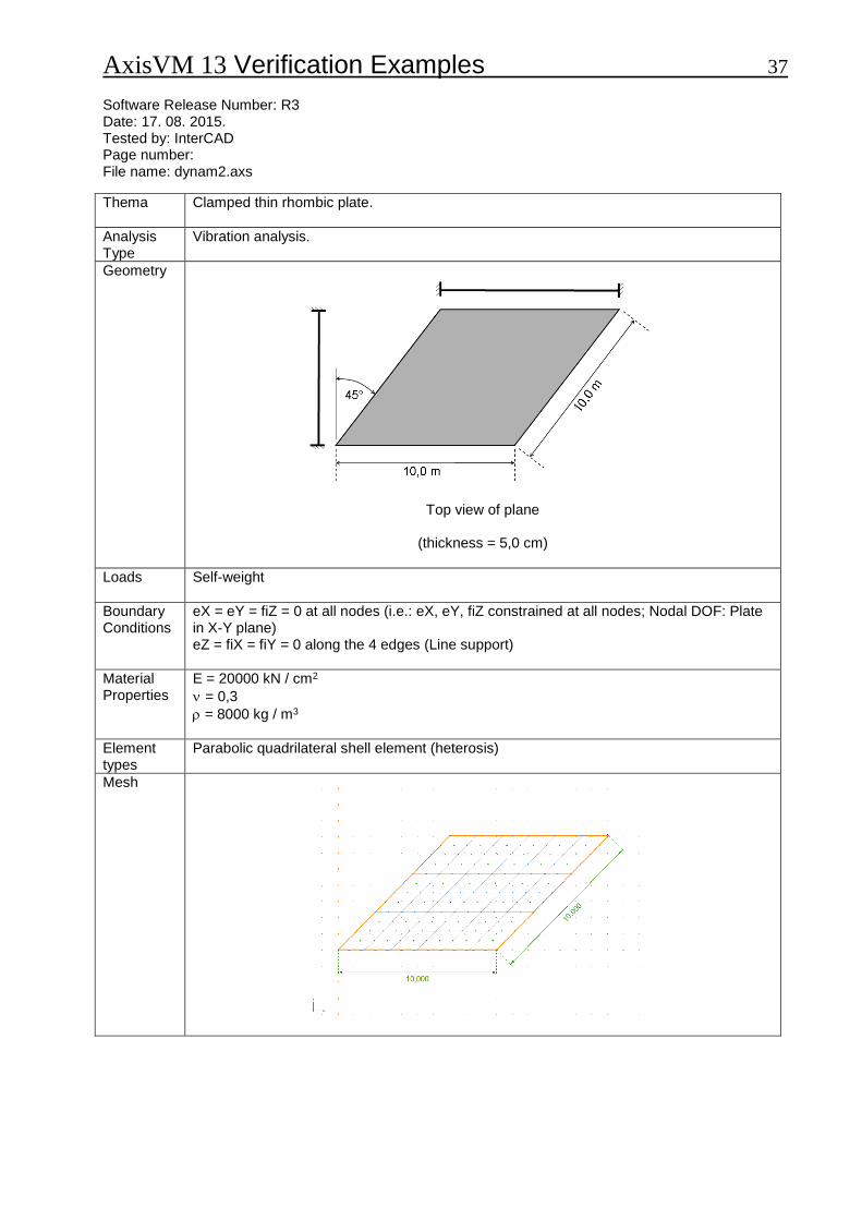
Thema
Clamped thin rhombic plate.
Analysis Type
Vibration analysis.
Geometry
Top view of plane
(thickness = 5,0 cm)
Loads
Self-weight
Boundary Conditions
eX = eY = fiZ = 0 at all nodes (i.e.: eX, eY, fiZ constrained at all nodes; Nodal DOF: Plate in X-Y plane) eZ = fiX = fiY = 0 along the 4 edges (Line support)
Material Properties
E = 20000 kN / cm2
= 0,3
= 8000 kg / m3
Element types
Parabolic quadrilateral shell element (heterosis)
Mesh

AxisVM 13 Verification Examples 38
Target
First 6 mode shapes
Results eR
0,506
0,470
0,433
0,397
0,361
0,325
0,289
0,253
0,217
0,181
0,144
0,108
0,072
0,036
0
Mode 1: f = 8,02 Hz eR
0,486
0,451
0,416
0,382
0,347
0,312
0,278
0,243
0,208
0,174
0,139
0,104
0,069
0,035
0
Mode 3: f = 18,41 Hz eR
0,498
0,462
0,427
0,391
0,356
0,320
0,284
0,249
0,213
0,178
0,142
0,107
0,071
0,036
0
Mode 5: f = 24,62 Hz
eR
0,463
0,429
0,396
0,363
0,330
0,297
0,264
0,231
0,198
0,165
0,132
0,099
0,066
0,033
0
Mode 2: f = 13,02 Hz eR
0,520
0,483
0,446
0,409
0,372
0,335
0,297
0,260
0,223
0,186
0,149
0,112
0,074
0,037
0
Mode 4: f = 19,33 Hz eR
0,449
0,417
0,385
0,353
0,321
0,289
0,257
0,225
0,192
0,160
0,128
0,096
0,064
0,032
0
Mode 6: f = 28,24 Hz
Results
Comparison with NAFEMS example
Mode NAFEMS (Hz) AxisVM (Hz) %
1 7,94 8,02 1,01
2 12,84 13,02 1,40
3 17,94 18,41 2,62
4 19,13 19,33 1,05
5 24,01 24,62 2,54
6 27,92 28,24 1,15

AxisVM 13 Verification Examples 39 Software Release Number: R3 Date: 17. 08. 2015. Tested by: InterCAD Page number: File name: dynam3.axs
Thema
Cantilevered thin square plate.
Analysis Type
Vibration analysis.
Geometry
Top view (thickness = 5,0 cm)
Loads
Self-weight
Boundary Conditions
eX = eY = eZ = fiX = fiY = fiZ = 0 along y-axis
Material Properties
E = 20000 kN / cm2
= 0,3
= 8000 kg / m3
Element types
Parabolic quadrilateral shell element (heterosis).
Mesh
AxisVM 13 Verification Examples 40
Target
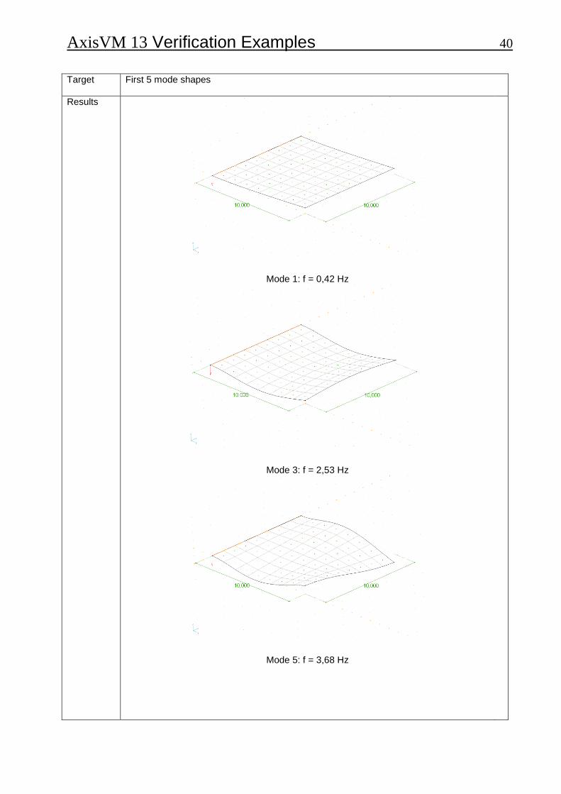
First 5 mode shapes
Results
Mode 1: f = 0,42 Hz
Mode 3: f = 2,53 Hz
Mode 5: f = 3,68 Hz

AxisVM 13 Verification Examples 41
Mode 2: f = 1,02 Hz
Mode 4: f = 3,22 Hz
Comparison with NAFEMS example
Mode NAFEMS (Hz) AxisVM (Hz) %
1 0,421 0,420 -0,24
2 1,029 1,020 -0,87
3 2,580 2,530 -1,94
4 3,310 3,220 -2,72
5 3,750 3,680 -1,87
AxisVM 13 Verification Examples 42 Software Release Number: R3 Date: 17. 08. 2015. Tested by: InterCAD Page number: File name: dynam4.axs
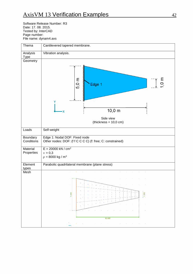
Thema
Cantilevered tapered membrane.
Analysis Type
Vibration analysis.
Geometry
Side view
(thickness = 10,0 cm)
Loads
Self-weight
Boundary Conditions
Edge 1: Nodal DOF: Fixed node Other nodes: DOF: (f f C C C C) (f: free; C: constrained)
Material Properties
E = 20000 kN / cm2
= 0,3
= 8000 kg / m3
Element types
Parabolic quadrilateral membrane (plane stress)
Mesh
AxisVM 13 Verification Examples 43
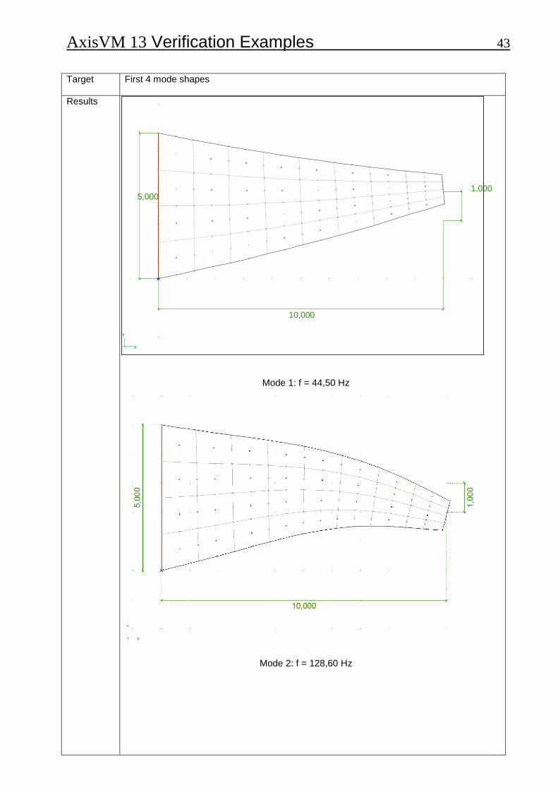
Target
First 4 mode shapes
Results
Mode 1: f = 44,50 Hz
Mode 2: f = 128,60 Hz
10,000
1,000 5,000
X
Y
AxisVM 13 Verification Examples 44
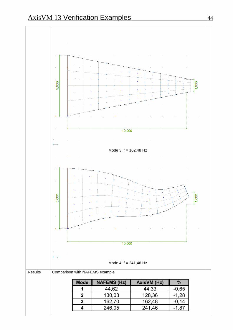
Mode 3: f = 162,48 Hz
Mode 4: f = 241,46 Hz
Results
Comparison with NAFEMS example
Mode NAFEMS (Hz) AxisVM (Hz) %
1 44,62 44,33 -0,65
2 130,03 128,36 -1,28
3 162,70 162,48 -0,14
4 246,05 241,46 -1,87
AxisVM 13 Verification Examples 45 Software Release Number: R3 Date: 17. 08. 2015. Tested by: InterCAD Page number: File name: dynam5.axs
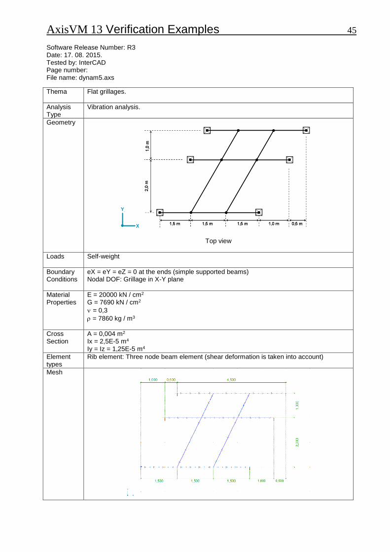
Thema
Flat grillages.
Analysis Type
Vibration analysis.
Geometry
Top view
Loads
Self-weight
Boundary Conditions
eX = eY = eZ = 0 at the ends (simple supported beams) Nodal DOF: Grillage in X-Y plane
Material Properties
E = 20000 kN / cm2 G = 7690 kN / cm2
= 0,3
= 7860 kg / m3
Cross Section
A = 0,004 m2 Ix = 2,5E-5 m4 Iy = Iz = 1,25E-5 m4
Element types
Rib element: Three node beam element (shear deformation is taken into account)
Mesh
AxisVM 13 Verification Examples 46
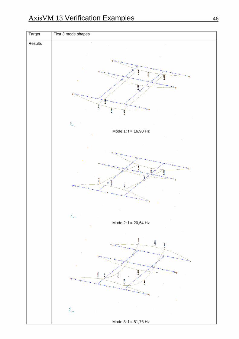
Target
First 3 mode shapes
Results
Mode 1: f = 16,90 Hz
Mode 2: f = 20,64 Hz
Mode 3: f = 51,76 Hz
AxisVM 13 Verification Examples 47
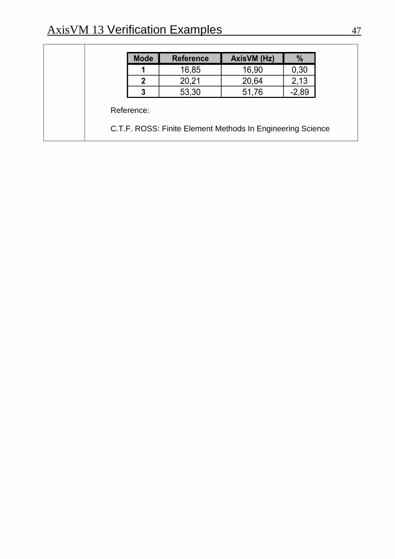
Mode Reference AxisVM (Hz) %
1 16,85 16,90 0,30
2 20,21 20,64 2,13
3 53,30 51,76 -2,89
Reference: C.T.F. ROSS: Finite Element Methods In Engineering Science

AxisVM 13 Verification Examples 48
BLANK
AxisVM 13 Verification Examples 49
Stability
AxisVM 13 Verification Examples 50 Software Release Number: R3 Date: 17. 08. 2015. Tested by: InterCAD Page number: File name: buckling1.axs
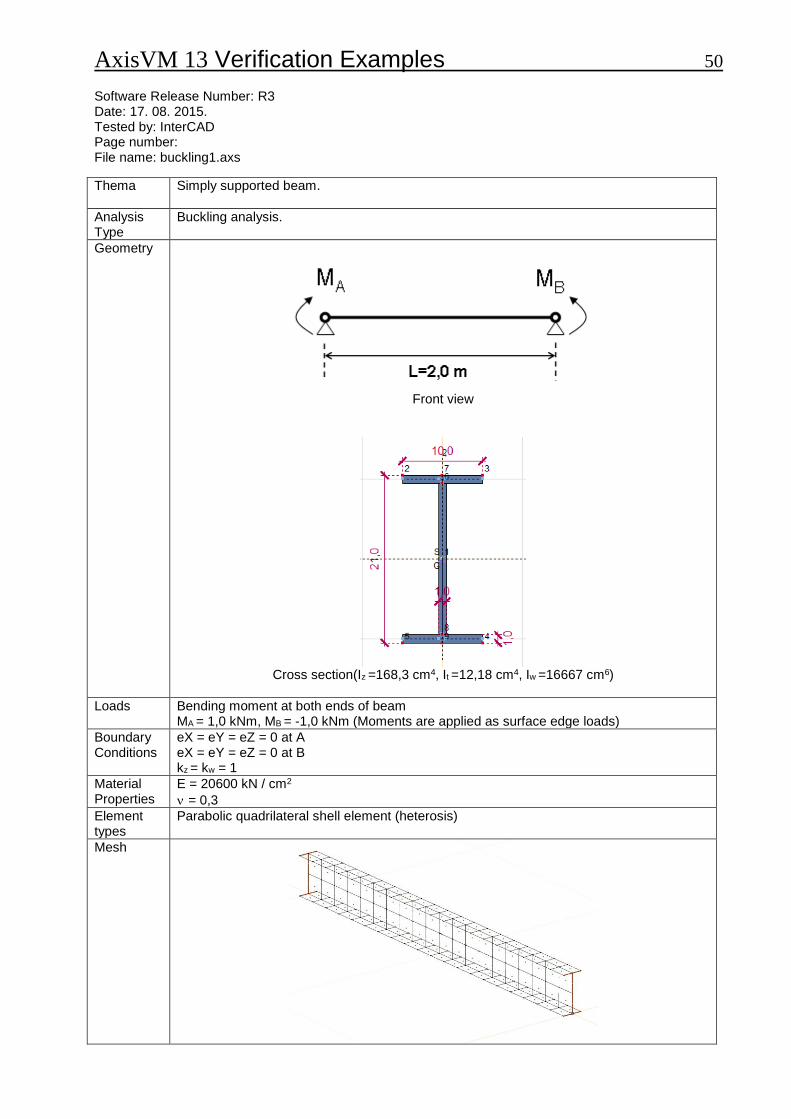
Thema
Simply supported beam.
Analysis Type
Buckling analysis.
Geometry
Front view
Cross section(Iz =168,3 cm4, It =12,18 cm4, Iw =16667 cm6)
Loads
Bending moment at both ends of beam MA = 1,0 kNm, MB = -1,0 kNm (Moments are applied as surface edge loads)
Boundary Conditions
eX = eY = eZ = 0 at A eX = eY = eZ = 0 at B kz = kw = 1
Material Properties
E = 20600 kN / cm2
= 0,3
Element types
Parabolic quadrilateral shell element (heterosis)
Mesh
AxisVM 13 Verification Examples 51
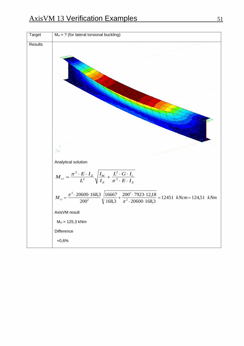
Target
Mcr = ? (for lateral torsional buckling)
Results
Analytical solution
Z
t
Z
WZcr
IE
IGL
I
I
L
IEM
2
2
2
2
kNmkNcmM cr 51,124124513,16820600
18,127923200
3,168
16667
200
3,168206002
2
2
2
AxisVM result Mcr = 125,3 kNm Difference +0,6%

AxisVM 13 Verification Examples 52 Software Release Number: R3 Date: 17. 08. 2015. Tested by: InterCAD Page number: File name: buckling2.axs
Thema
Simply supported beam.
Analysis Type
Buckling analysis.
Geometry
Front view (L = 1,0 m)
1
2
3 4
5
S
G
1
2
12,0
10
,0
y
z
1
2
3 4
5
S
G
1
2
30,0
10
,0
y
z
Section A1 Section A2
Cross-sections
Loads
P = -1,0 kN at point B.
Boundary Conditions
eX = eY = eZ = 0 at A eY = eZ = 0 at B
Material Properties
E = 20000 kN / cm2
= 0,3
Element types
Beam element
Target
Pcr = ? (for inplane buckling)
Results
Theory AxisVM e [%]
Pcr [kN] 3,340 3,337 -0,09
AxisVM 13 Verification Examples 53
Design
AxisVM 13 Verification Examples 54 Software Release Number: R3 Date: 17. 08. 2015. Tested by: InterCAD Page number: File name: RC column1.axs
Thema
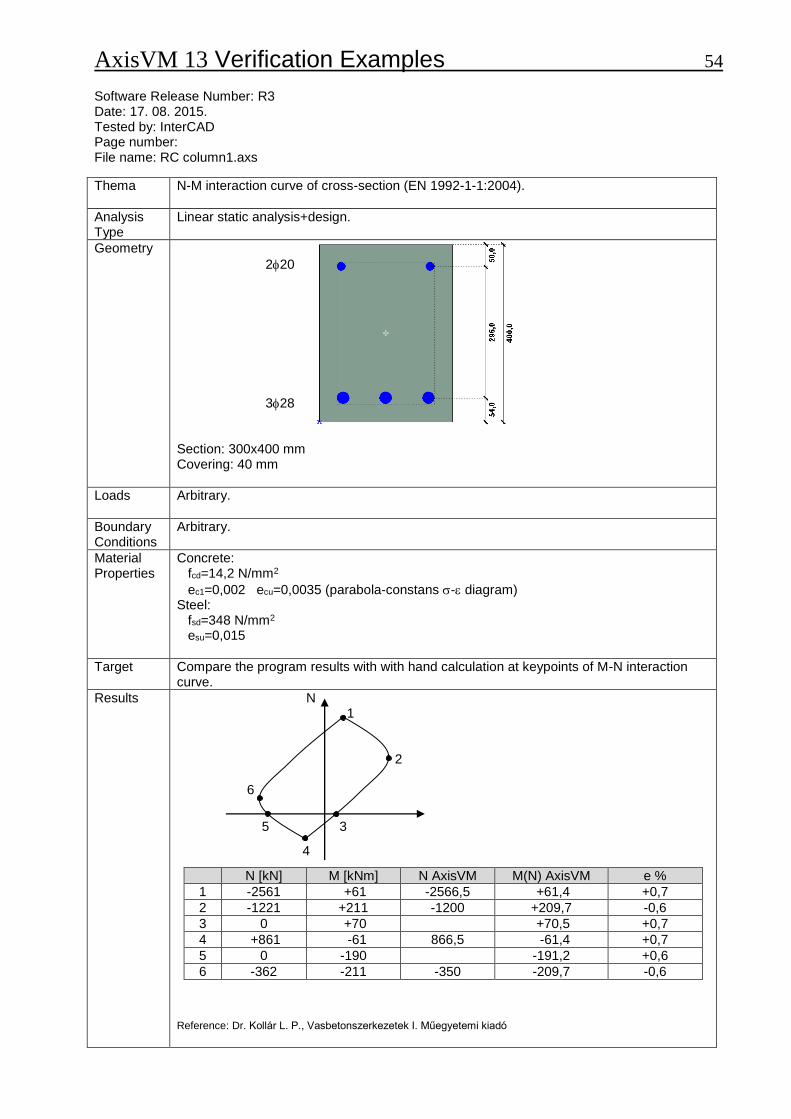
N-M interaction curve of cross-section (EN 1992-1-1:2004).
Analysis Type
Linear static analysis+design.
Geometry
220
328 Section: 300x400 mm Covering: 40 mm
Loads
Arbitrary.
Boundary Conditions
Arbitrary.
Material Properties
Concrete: fcd=14,2 N/mm2
ec1=0,002 ecu=0,0035 (parabola-constans - diagram) Steel: fsd=348 N/mm2 esu=0,015
Target
Compare the program results with with hand calculation at keypoints of M-N interaction curve.
Results
N 1 2 6
5 3
4
Reference: Dr. Kollár L. P., Vasbetonszerkezetek I. Műegyetemi kiadó
N [kN] M [kNm] N AxisVM M(N) AxisVM e %
1 -2561 +61 -2566,5 +61,4 +0,7
2 -1221 +211 -1200 +209,7 -0,6
3 0 +70 +70,5 +0,7
4 +861 -61 866,5 -61,4 +0,7
5 0 -190 -191,2 +0,6
6 -362 -211 -350 -209,7 -0,6
AxisVM 13 Verification Examples 55 Software Release Number: R3 Date: 17. 08. 2015. Tested by: InterCAD Page number: File name: beam1.axs
Thema
RC beam deflection according to EC2, EN 1992-1-1:2010.
Analysis Type
Material nonlinear analysis.
Geometry
q = 17 kN/m
L = 5,60 m
Side view
220 35 cm covering = 3 cm
= 0,5
420
25 cm
Section
Loads
q = 17 kN /m distributed load
Boundary Conditions
Simply supported beam.
Material Properties
Concrete: C25/30, = 2,1 Steel: B500B
Element types
Parabolic quadrilateral plate element (Heterosis)
Target
ez, max
AxisVM 13 Verification Examples 56
Results
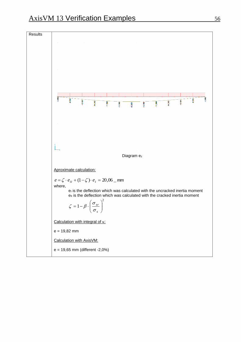
Diagram ez
Aproximate calculation:
mmeee III _06,20)1(
where, eI is the deflection which was calculated with the uncracked inertia moment eII is the deflection which was calculated with the cracked inertia moment
2
1
s
sr
Calculation with integral of : e = 19,82 mm Calculation with AxisVM: e = 19,65 mm (different -2,0%)

AxisVM 13 Verification Examples 57 Software Release Number: R3 Date: 17. 08. 2015. Tested by: InterCAD Page number: File name: beam2.axs
Thema
Required steel reinforcement of RC plate according to EC2, EN 1992-1-1:2004.
Analysis Type
Linear analysis.
Geometry
Side view
Cross-section
Loads
Pz = -50 kN point load
Boundary Conditions
Clamped cantilever plate. Fix line support on clamped edge. Nodal DOF: Plate in X-Y plane
Material Properties
Concrete: C25/30 Steel: B500A
Element types
Parabolic quadrilateral plate element (heterosis)
Mesh
Top view

AxisVM 13 Verification Examples 58
Target
AXT steel reinforcement along x direction at the top of the support
Results
Diagram AXT
Calculation according to EC2:
2/6,165,1
25mmNfcd 2/435
15,1
500mmNf yd
54,0435200000035,0
200000035,085,00
ydScu
Scuc
fE
Ec
d = 300 – 53 = 247 mm
kNmx
dfxbMM ccdcRdsd 200
2
55
439 hxc
54,022,0247
550 c
cc
d
x Steel reinforcement is yielding
22099435
6,16100055mm
f
fxbA
yd
cdcS
Calculation with AxisVM:
AXT = mmm /2093 2
Different = -0,3 %
AxisVM 13 Verification Examples 59 Software Release Number: R3 Date: 17. 08. 2015. Tested by: InterCAD Page number: File name: 3_10 Plastic biaxial bending interaction.axs
Thema
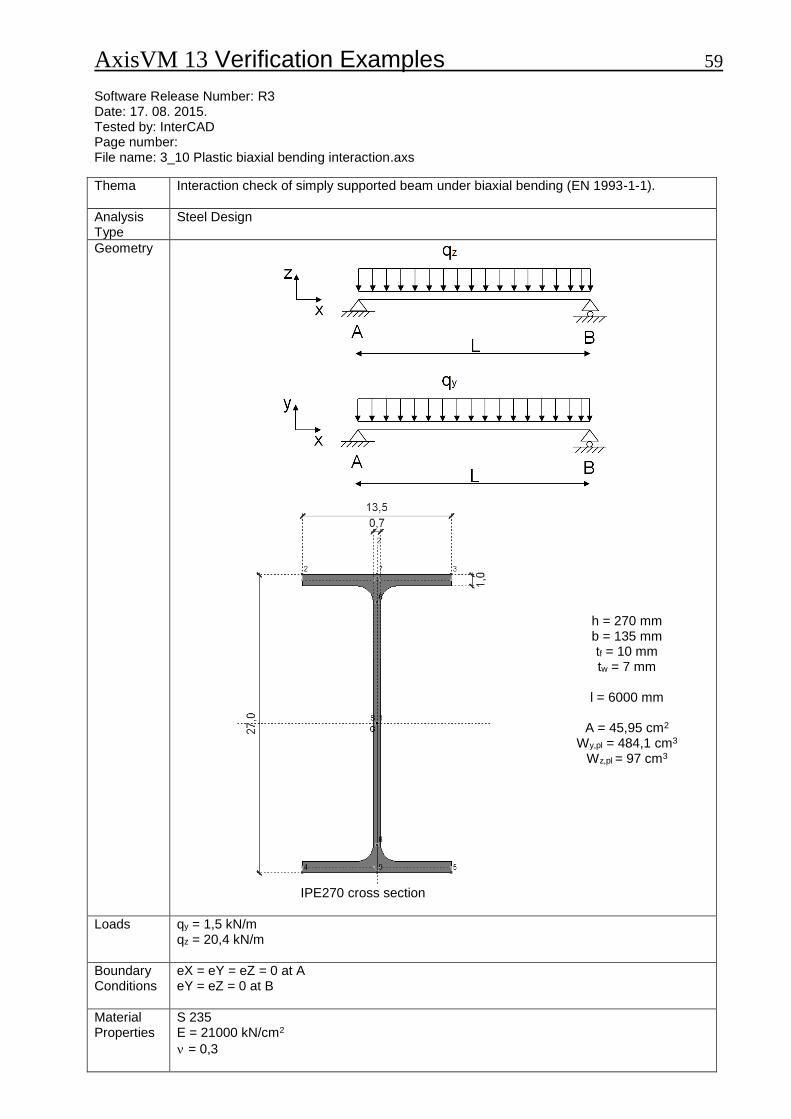
Interaction check of simply supported beam under biaxial bending (EN 1993-1-1).
Analysis Type
Steel Design
Geometry
h = 270 mm b = 135 mm tf = 10 mm tw = 7 mm
l = 6000 mm
A = 45,95 cm2
Wy,pl = 484,1 cm3 Wz,pl = 97 cm3
IPE270 cross section
Loads
qy = 1,5 kN/m qz = 20,4 kN/m
Boundary Conditions
eX = eY = eZ = 0 at A eY = eZ = 0 at B
Material Properties
S 235 E = 21000 kN/cm2
= 0,3

AxisVM 13 Verification Examples 60
Element types
Beam element
Target
Interaction check taking into account plastic resistances
Results
Analytical solution in the following book: Dunai, L., Horváth, L., Kovács, N., Verőci, B., Vigh, L. G.: “Acélszerkezetek méretezése az Eurocode 3 alapján, Gyakorlati útmutató” (Design of steel structures according to Eurocode 3, ) Magyar Mérnök Kamara Tartószerkezeti tagozata, Budapest, 2009. Exercise 3.10., page 28.
Analitical solution
AxisVM e[%]
My,Ed [kNm] 91,8 91,8 -
Mz,Ed [kNm] 6,75 6,75 -
Mpl,y,Rd [kNm] 113,74 113,76 +0,02
Mpl,z,Rd [kNm] 22,78 22,79 +0,04
α 2 2 -
β 1 1 -
capacity ratio [-] 0,948 0,947 -0,11
AxisVM 13 Verification Examples 61 Software Release Number: R3 Date: 17. 08. 2015. Tested by: InterCAD Page number: File name: 3_12 _MNV_Interaction.axs
Thema
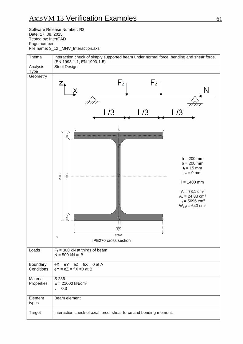
Interaction check of simply supported beam under normal force, bending and shear force. (EN 1993-1-1, EN 1993-1-5)
Analysis Type
Steel Design
Geometry
h = 200 mm b = 200 mm tf = 15 mm tw = 9 mm
l = 1400 mm
A = 78,1 cm2
Av = 24,83 cm2 Iy = 5696 cm3
Wy,pl = 643 cm3
IPE270 cross section
Loads
Fz = 300 kN at thirds of beam N = 500 kN at B
Boundary Conditions
eX = eY = eZ = fiX = 0 at A eY = eZ = fiX =0 at B
Material Properties
S 235 E = 21000 kN/cm2
= 0,3
Element types
Beam element
Target
Interaction check of axial force, shear force and bending moment.

AxisVM 13 Verification Examples 62
Results
Analytical solution in the following book: Dunai, L., Horváth, L., Kovács, N., Verőci, B., Vigh, L. G.: “Acélszerkezetek méretezése az Eurocode 3 alapján, Gyakorlati útmutató” (Design of steel structures according to Eurocode 3, ) Magyar Mérnök Kamara Tartószerkezeti tagozata, Budapest, 2009. Exercise 3.12., page 31-33.
Analytical solution
AxisVM results
e[%]
NEd [kN] 500 500 -
Vz,Ed [kN] 300 300 -
My,Ed [kNm] 140 140 -
Pure compression
Npl,Rd [kN] 2148 2148 -
capacity ratio [-] 0,233 0,233 -
Pure shear
Vpl,z,Rd [kN] 394,2 394,5 +0,08
capacity ratio [-] 0,761 0,761 -
Pure bending
Mpl,y,Rd [kNm] 176,8 176,7 -0,06
capacity ratio [-] 0,792 0,792 -
Interaction check
0,273 0,271 -0,73
MV,Rd [kNm] 163,96 163,93 -0,02
n 0,233 0,233 -
a 0,232 0,232 -
MNV,Rd [kNm] 142,2 142,2 -
capacity ratio [-] 0,985 0,984 -0,10
AxisVM 13 Verification Examples 63 Software Release Number: R3 Date: 17. 08. 2015. Tested by: InterCAD Page number: File name: 3_15 Központosan nyomott rúd - I szelvény.axs
Thema
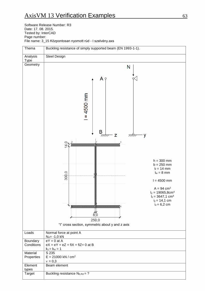
Buckling resistance of simply supported beam (EN 1993-1-1).
Analysis Type
Steel Design
Geometry
h = 300 mm b = 250 mm tf = 14 mm tw = 8 mm
l = 4500 mm
A = 94 cm2
Iy = 19065,8cm4 Iz = 3647,1 cm4
iy = 14,1 cm iz = 6,2 cm
“I” cross section, symmetric about y and z axis
Loads
Normal force at point A NA= -1,0 kN
Boundary Conditions
eY = 0 at A eX = eY = eZ = fiX = fiZ= 0 at B kz = kw = 1
Material Properties
S 235 E = 21000 kN / cm2
= 0,3
Element types
Beam element
Target
Buckling resistance Nb,Rd = ?

AxisVM 13 Verification Examples 64
Results
Analytical solution in the following book: Dunai, L., Horváth, L., Kovács, N., Verőci, B., Vigh, L. G.: “Acélszerkezetek méretezése az Eurocode 3 alapján, Gyakorlati útmutató” (Design of steel structures according to Eurocode 3, ) Magyar Mérnök Kamara Tartószerkezeti tagozata, Budapest, 2009. Exercise 3.15., P. 37-39.
Analytical solution
AxisVM e[%]
y [-] * 0,673 0,673 -
z [-] 0,771 0,769 -0,26
Χy [-] * 0,8004 0,7989 -0,19
Χz [-] 0,6810 0,6815 +0,07
Nb,Rd [kN] 1504,3 1505,3 +0,07
AxisVM 13 Verification Examples 65 Software Release Number: R3 Date: 17. 08. 2015. Tested by: InterCAD Page number: File name: 3_21 Központosan nyomott rúd - T szelvény.axs
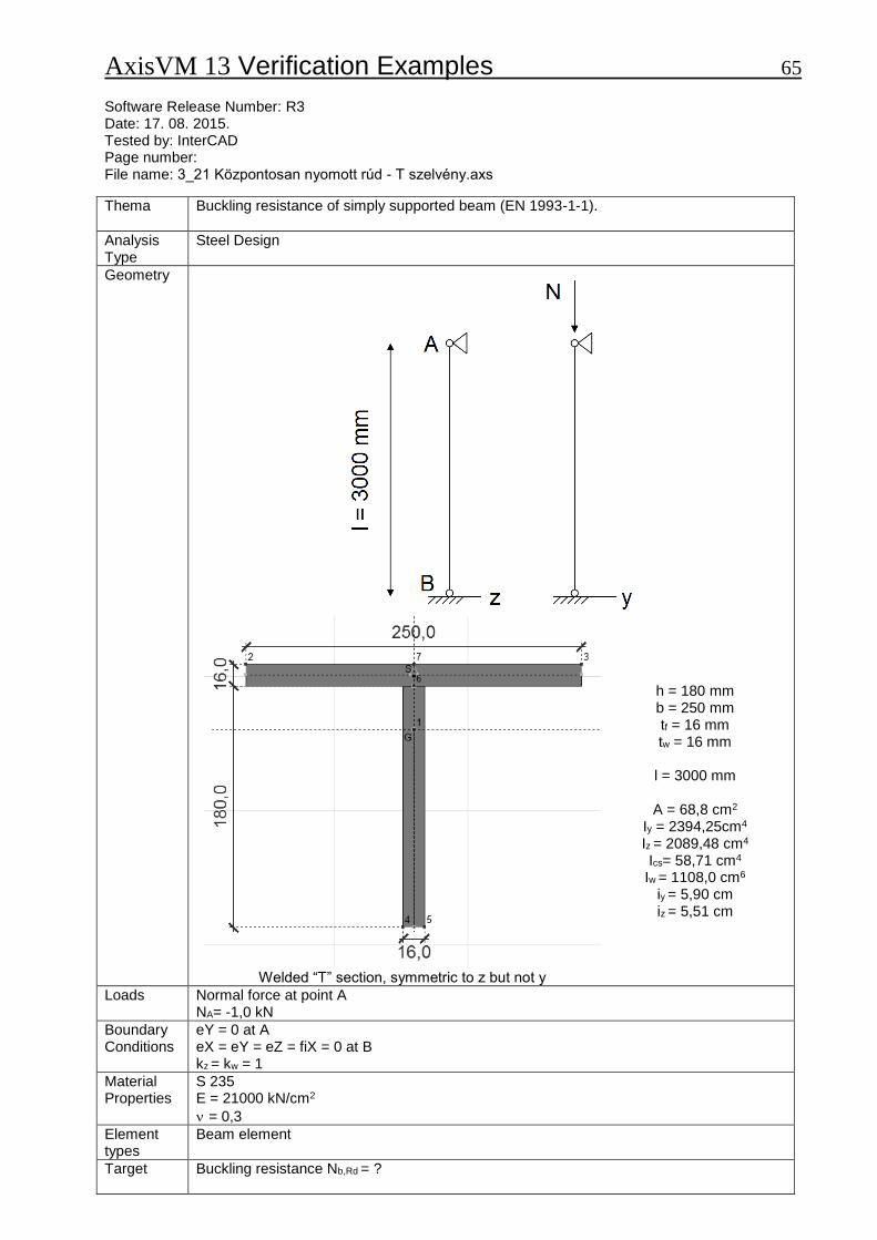
Thema
Buckling resistance of simply supported beam (EN 1993-1-1).
Analysis Type
Steel Design
Geometry
h = 180 mm b = 250 mm tf = 16 mm tw = 16 mm
l = 3000 mm
A = 68,8 cm2
Iy = 2394,25cm4 Iz = 2089,48 cm4 Ics= 58,71 cm4
Iw = 1108,0 cm6
iy = 5,90 cm
iz = 5,51 cm
Welded “T” section, symmetric to z but not y
Loads
Normal force at point A NA= -1,0 kN
Boundary Conditions
eY = 0 at A eX = eY = eZ = fiX = 0 at B kz = kw = 1
Material Properties
S 235 E = 21000 kN/cm2
= 0,3
Element types
Beam element
Target
Buckling resistance Nb,Rd = ?
AxisVM 13 Verification Examples 66
Results
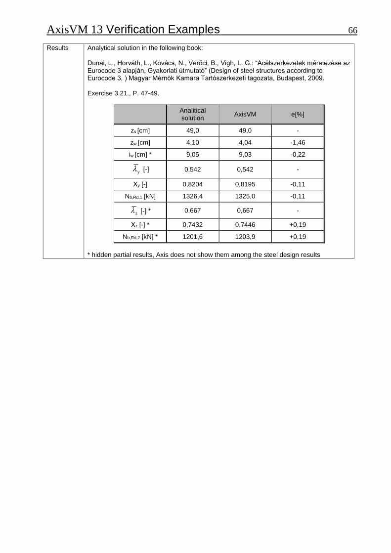
Analytical solution in the following book: Dunai, L., Horváth, L., Kovács, N., Verőci, B., Vigh, L. G.: “Acélszerkezetek méretezése az Eurocode 3 alapján, Gyakorlati útmutató” (Design of steel structures according to Eurocode 3, ) Magyar Mérnök Kamara Tartószerkezeti tagozata, Budapest, 2009. Exercise 3.21., P. 47-49.
Analitical solution
AxisVM e[%]
zs [cm] 49,0 49,0 -
zw [cm] 4,10 4,04 -1,46
iw [cm] * 9,05 9,03 -0,22
y [-] 0,542 0,542 -
Χy [-] 0,8204 0,8195 -0,11
Nb,Rd,1 [kN] 1326,4 1325,0 -0,11
z [-] * 0,667 0,667 -
Χz [-] * 0,7432 0,7446 +0,19
Nb,Rd,2 [kN] * 1201,6 1203,9 +0,19
* hidden partial results, Axis does not show them among the steel design results
AxisVM 13 Verification Examples 67 Software Release Number: R3 Date: 17. 08. 2015. Tested by: InterCAD Page number: File name: Külpontosan nyomott rúd - RHS szelvény.axs
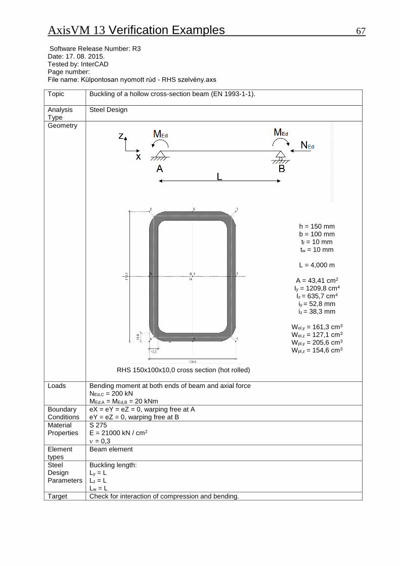
Topic
Buckling of a hollow cross-section beam (EN 1993-1-1).
Analysis Type
Steel Design
Geometry
h = 150 mm b = 100 mm tf = 10 mm tw = 10 mm
L = 4,000 m
A = 43,41 cm2
Iy = 1209,8 cm4 Iz = 635,7 cm4 iy = 52,8 mm iz = 38,3 mm
Wel,y = 161,3 cm3 Wel,z = 127,1 cm3 Wpl,y = 205,6 cm3 Wpl,z = 154,6 cm3
RHS 150x100x10,0 cross section (hot rolled)
Loads
Bending moment at both ends of beam and axial force NEd,C = 200 kN MEd,A = MEd,B = 20 kNm
Boundary Conditions
eX = eY = eZ = 0, warping free at A eY = eZ = 0, warping free at B
Material Properties
S 275 E = 21000 kN / cm2
= 0,3
Element types
Beam element
Steel Design Parameters
Buckling length: Ly = L Lz = L Lw = L
Target Check for interaction of compression and bending.
AxisVM 13 Verification Examples 68
Results
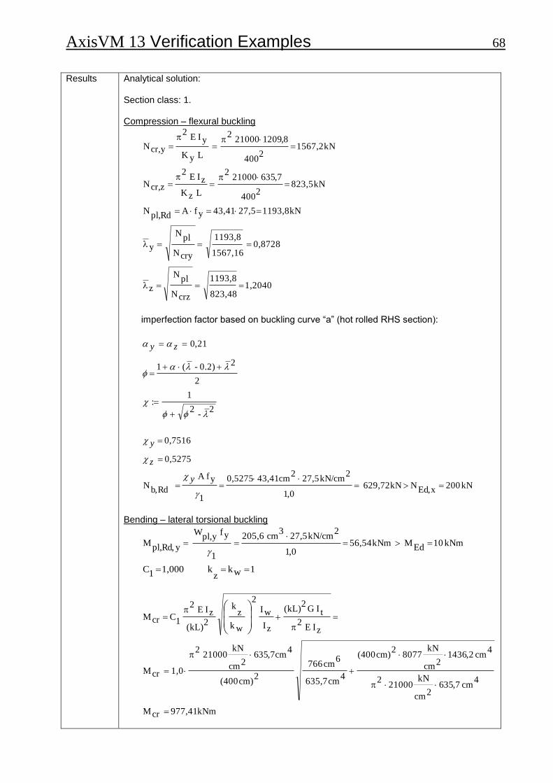
Analytical solution: Section class: 1. Compression – flexural buckling
1,2040 823,48
1193,8
crzN
plN
z
0,8728 1567,16
1193,8
cryN
plN
y
kN 1193,8 27,5 43,41 yfA Rdpl,
N
kN 823,5 2
400
7,356 21000 2
L zK
zI E 2
zcr,N
kN 1567,2 2
400
8,2091 21000 2
L yK
yI E 2
ycr,N
imperfection factor based on buckling curve “a” (hot rolled RHS section):
2-
2
1:
2
20.2)-(1
21,0
zy
kN 200 xEd,
N kN 629,72 0,1
2kN/cm 27,5
2cm 43,41 0,5275
1
yfA
Rdb,N
0,5275
0,7516
y
z
y
Bending – lateral torsional buckling
kNm 10 Ed
M kNm 56,54 0,1
2kN/cm 27,5
3cm 205,6
1
yf ypl,
W
yRd,pl,
M
1 wk z
k 1,000 1C
kNm 977,41 crM
4cm 7,356
2cm
kN 21000
2
4cm 2,4361
2cm
kN 8077
2cm) (400
4
cm 635,7
6cm 766
2
cm) (400
4cm7,356
2cm
kN 21000
2
1,0crM
zI E 2
t IG 2
(kL)
zI
wI2
wk
zk
2
(kL)
zI E 2
1C crM
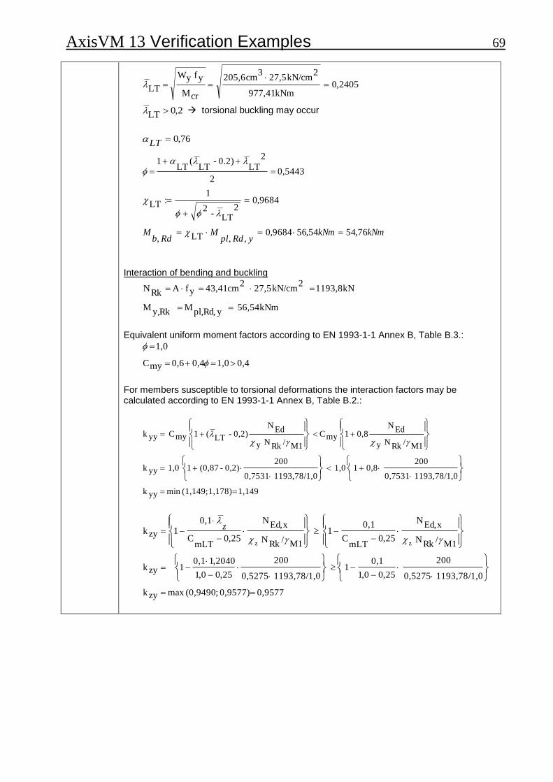
AxisVM 13 Verification Examples 69
2405,0kNm 977,41
2kN/cm 27,5
3cm 205,6
crM
yf yW LT
2,0LT torsional buckling may occur
76,0LT
kNmkNmyRdpl
MRdb
M 76,5454,569684,0,,LT,
9684,02
LT-2
1:LT
0,5443 2
2
LT0.2)-
LT(
LT1
Interaction of bending and buckling
56,54kNm y Rd,pl,
M Rk y,
M
kN 1193,8 2
kN/cm 27,5 2
cm 43,41 yfA Rk
N
Equivalent uniform moment factors according to EN 1993-1-1 Annex B, Table B.3.:
0,4 1,0 0,4 0,6 myC
1,0
For members susceptible to torsional deformations the interaction factors may be calculated according to EN 1993-1-1 Annex B, Table B.2.:
1,149 1,178) ; (1,149min yyk
/1,01193,78 0,7531
200 0,81 1,0
/1,01193,78 0,7531
200 0,2)-(0,871 1,0 yyk
M1/Rk
N y
EdN
0,8 1 myC
M1/Rk
N y
EdN
0,2)-LT( 1 myC yyk
0,9577 0,9577) ; (0,9490max zyk
/1,01193,78 0,5275
200
25,00,1
0,11
/1,01193,78 0,5275
200
25,00,1
2040,10,1 1 zyk
M1/Rk
N
xEd,N
25,0
mLTC
0,11
M1/Rk
N
xEd,N
25,0mLT
C
0,1 1 zyk
zz
z
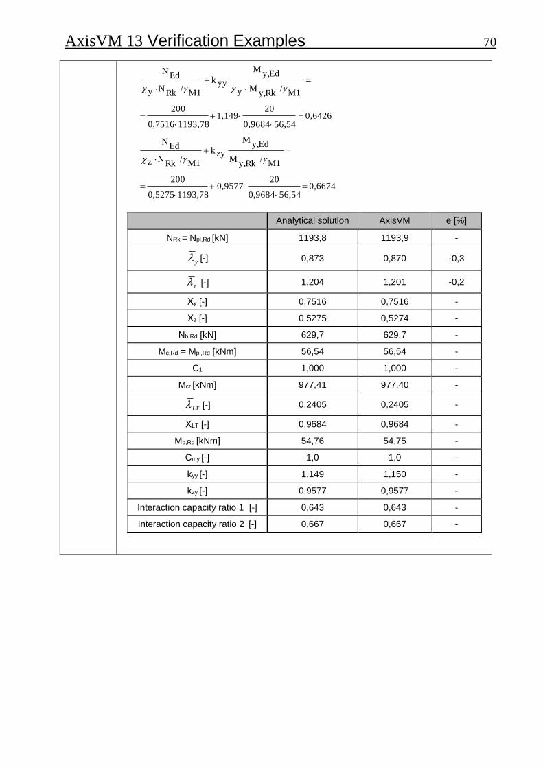
AxisVM 13 Verification Examples 70
0,6674 56,540,9684
20 0,9577
1193,78 0,5275
200
M1 /
Rky,M
Edy,M
zyk
M1 /Rk
Nz
EdN
0,6426 56,540,9684
20 1,149
1193,780,7516
200
M1 /
Rky,My
Edy,M
yyk
M1 /Rk
Ny
EdN
Analytical solution AxisVM e [%]
NRk = Npl,Rd [kN] 1193,8 1193,9 -
y [-] 0,873 0,870 -0,3
z [-] 1,204 1,201 -0,2
Χy [-] 0,7516 0,7516 -
Χz [-] 0,5275 0,5274 -
Nb,Rd [kN] 629,7 629,7 -
Mc,Rd = Mpl,Rd [kNm] 56,54 56,54 -
C1 1,000 1,000 -
Mcr [kNm] 977,41 977,40 -
LT [-] 0,2405 0,2405 -
ΧLT [-] 0,9684 0,9684 -
Mb,Rd [kNm] 54,76 54,75 -
Cmy [-] 1,0 1,0 -
kyy [-] 1,149 1,150 -
kzy [-] 0,9577 0,9577 -
Interaction capacity ratio 1 [-] 0,643 0,643 -
Interaction capacity ratio 2 [-] 0,667 0,667 -
AxisVM 13 Verification Examples 71 Software Release Number: R3 Date: 17. 08. 2015. Tested by: InterCAD Page number: File name: 3_26 Külpontosan nyomott rúd - I szelvény.axs
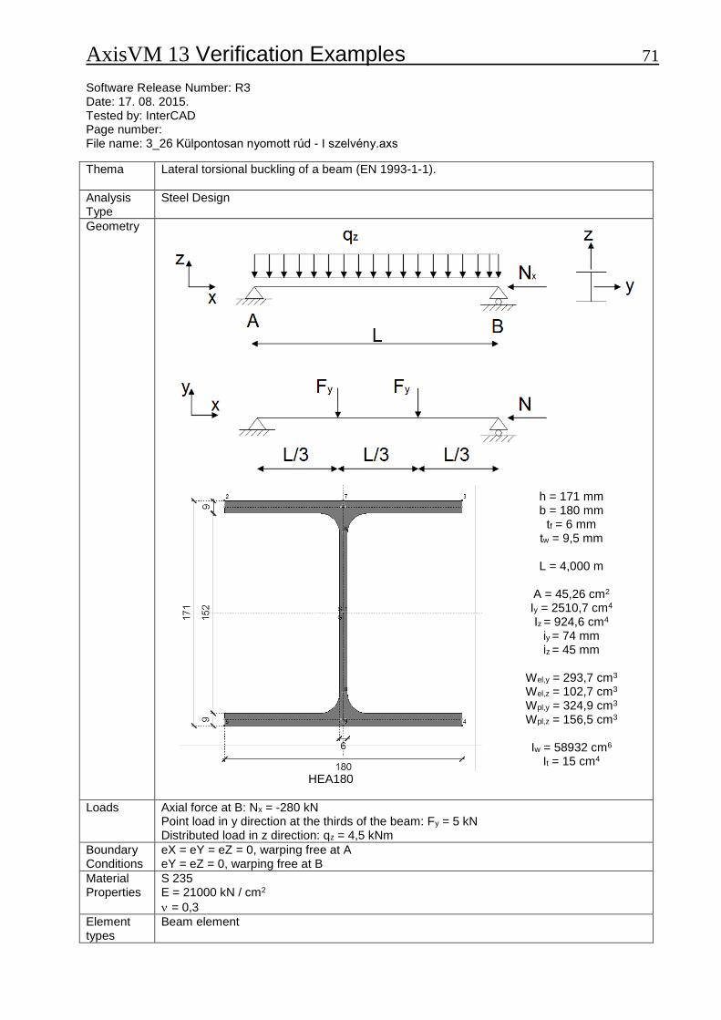
Thema
Lateral torsional buckling of a beam (EN 1993-1-1).
Analysis Type
Steel Design
Geometry
h = 171 mm b = 180 mm
tf = 6 mm tw = 9,5 mm
L = 4,000 m
A = 45,26 cm2
Iy = 2510,7 cm4 Iz = 924,6 cm4
iy = 74 mm iz = 45 mm
Wel,y = 293,7 cm3 Wel,z = 102,7 cm3 Wpl,y = 324,9 cm3 Wpl,z = 156,5 cm3
Iw = 58932 cm6
It = 15 cm4 HEA180
Loads
Axial force at B: Nx = -280 kN Point load in y direction at the thirds of the beam: Fy = 5 kN Distributed load in z direction: qz = 4,5 kNm
Boundary Conditions
eX = eY = eZ = 0, warping free at A eY = eZ = 0, warping free at B
Material Properties
S 235 E = 21000 kN / cm2
= 0,3
Element types
Beam element
AxisVM 13 Verification Examples 72
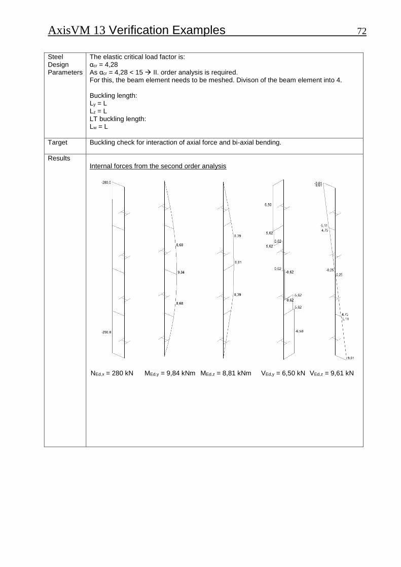
Steel Design Parameters
The elastic critical load factor is: αcr = 4,28 As αcr = 4,28 < 15 II. order analysis is required. For this, the beam element needs to be meshed. Divison of the beam element into 4. Buckling length: Ly = L Lz = L LT buckling length: Lw = L
Target
Buckling check for interaction of axial force and bi-axial bending.
Results
Internal forces from the second order analysis
NEd,x = 280 kN MEd,y = 9,84 kNm MEd,z = 8,81 kNm VEd,y = 6,50 kN VEd,z = 9,61 kN
AxisVM 13 Verification Examples 73
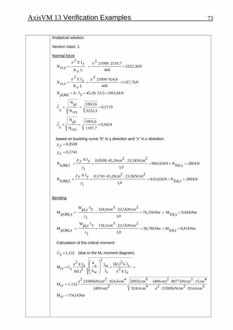
Analytical solution: Section class: 1. Normal force
0,9424 1197,7
1063,6
crzN
plN
0,5719 3252,3
1063,6
cryN
plN
kN 1063,6 23,5 45,26 yfA Rdpl,
N
kN 1197,7 400
924,6 21000 2
L zK
zI E 2
zcr,N
kN 3252,3 400
2510,7 21000 2
L yK
yI E 2
ycr,N
z
y
based on buckling curve “b” in y direction and “c” in z direction:
kN 280 xEd,
N kN 610,62 0,1
223,5kN/cm
245,26cm 0,5741
1
yfA
Rd,2b,N
kN 280xEd,
N kN 904,92 0,1
223,5kN/cm
245,26cm 0,8508
1
yfA
Rd,1b,N
0,5741
0,8508
z
y
z
y
Bending
kNm 8,81 zEd,
M kNm 36,78 0,1
2kN/cm 23,5
3cm 156,5
1
yf zpl,
W
zRd,pl,
M
kNm 9,84 yEd,
M kNm 76,35 0,1
2kN/cm 23,5
3cm 324,9
1
yf ypl,
W
yRd,pl,
M
Calculation of the critical moment:
1,132 1C (due to the My moment diagram)
kNm 1,741crM
4cm 924,6
2kN/cm 21000
2
4cm 15
2kN/cm 8077
2cm) (400
4
cm 924,6
6cm 58932
2
cm) (400
4cm 924,6
2kN/cm 21000
2
1,132crM
zI E 2
t IG 2
(kL)
zI
wI2
wk
zk
2
(kL)
zI E 2
1C crM

AxisVM 13 Verification Examples 74
For rolled section, the following procedure may be used to determine the reduction factor (EN 1993-1-1,Paragraph 6.3.2.3.):
kNmkNmyRdpl
MRdb
M 81,6735,768881,0,,LT,
8881,02
LT0.75-2
1:LT
0,7090 2
2
LT0.750.4)-
LT(
LT1
6622,0kNm 174,10
2kN/cm 23,5
3cm 324,9
crM
yf yW LT
Interaction of axial force and bi-axial bending
kNm 36,78 zRd,pl,
M Rk z,
M
kNm 76,35 y Rd,pl,
M Rk y,
M
kN 1063,6 Rdpl,
N Rk
N
Equivalent uniform moment factors according to EN 1993-1-1 Annex B, Table B.3.:
0 0, in both directions
0,95 0,050,95 mLT
C my
C (distributed load)
0,90 0,100,90 mzC (concentrated load)
0,9383 0,9345) ; (0,9383max zyk
/1,01063,6 0,5741
280
25,095,0
0,11
/1,01063,6 0,5741
280
25,095,0
9424,00,1 1 zyk
M1/Rk
N
xEd,N
25,0
mLTC
0,11
M1/Rk
N
xEd,N
25,0mLT
C
0,1 1 zyk
1,0593 1,1851) ; (1,0593min yyk
/1,01063,6 0,8508
280 0,81 0,95
/1,01063,6 0,8508
280 0,2)-(0,57191 0,95 yyk
M1/Rk
N y
xEd,N
0,8 1 myC
M1/Rk
N y
xEd,N
0,2)-( 1 myC yyk
zz
z
y
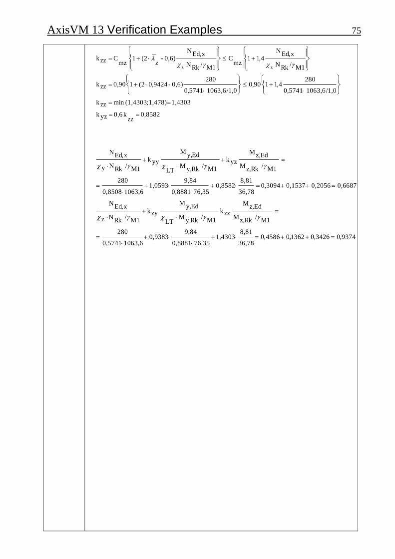
AxisVM 13 Verification Examples 75
0,8582 zz
k 0,6 yzk
1,4303 1,478) ; (1,4303min zzk
/1,01063,6 0,5741
2804,11 90,0
/1,01063,6 5741,0
2800,6)-9424,0(2 1 0,90 zzk
M1/Rk
N
xEd,N
4,11 mz
C
M1/Rk
N
xEd,N
0,6)-(2 1 mz
C zzk
zz
z
9374,03426,01362,04586,0 36,78
8,81 1,4303
76,350,8881
9,840,9383
1063,60,5741
280
M1 /
Rkz,M
Edz,M
zzk M1 /
Rky,M
LT
Edy,M
zyk
M1 /Rk
Nz
xEd,N
0,66870,20560,15370,3094 36,78
8,81 0,8582
76,350,8881
9,84 1,0593
1063,60,8508
280
M1 /
Rkz,M
Edz,M
yzk M1 /
Rky,M
LT
Edy,M
yyk
M1 /Rk
Ny
xEd,N
AxisVM 13 Verification Examples 76
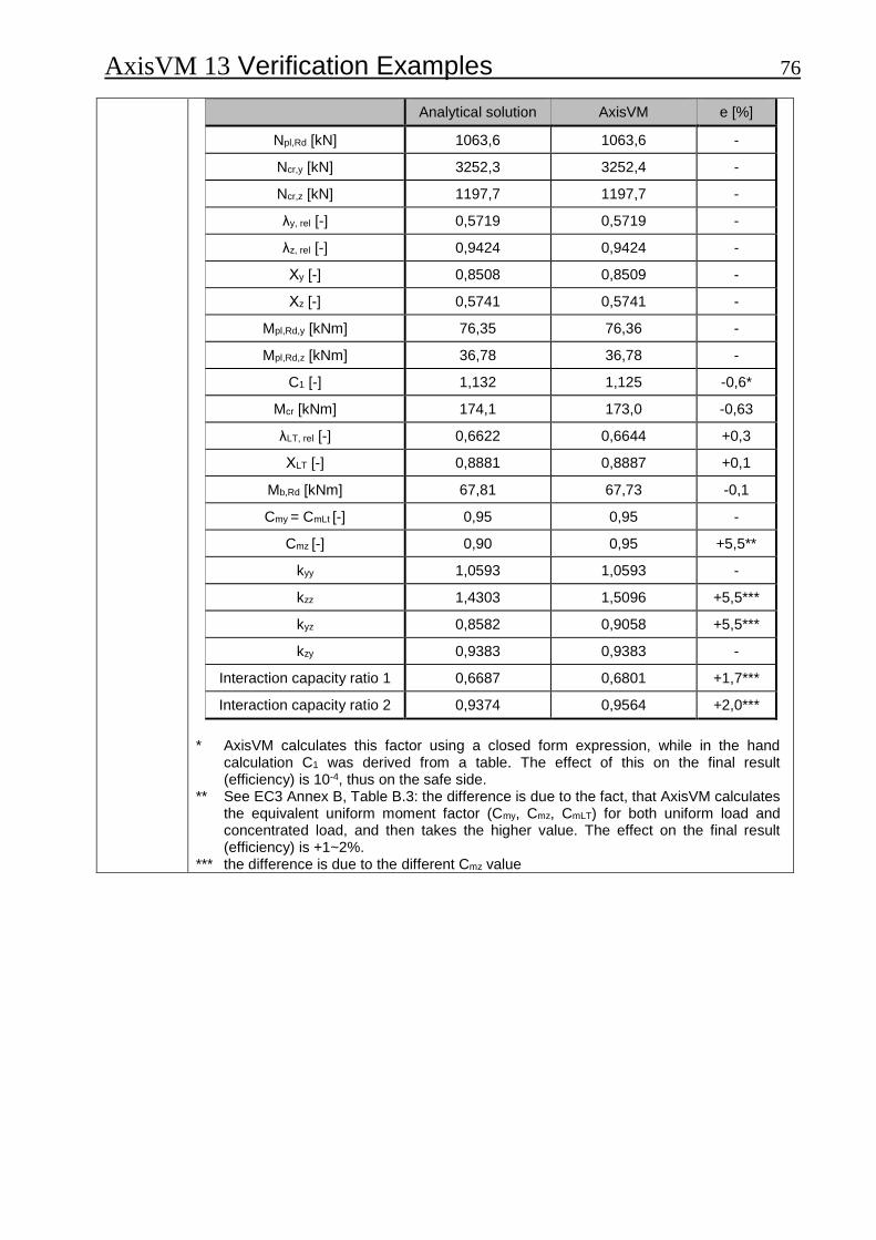
Analytical solution AxisVM e [%]
Npl,Rd [kN] 1063,6 1063,6 -
Ncr,y [kN] 3252,3 3252,4 -
Ncr,z [kN] 1197,7 1197,7 -
λy, rel [-] 0,5719 0,5719 -
λz, rel [-] 0,9424 0,9424 -
Χy [-] 0,8508 0,8509 -
Χz [-] 0,5741 0,5741 -
Mpl,Rd,y [kNm] 76,35 76,36 -
Mpl,Rd,z [kNm] 36,78 36,78 -
C1 [-] 1,132 1,125 -0,6*
Mcr [kNm] 174,1 173,0 -0,63
λLT, rel [-] 0,6622 0,6644 +0,3
ΧLT [-] 0,8881 0,8887 +0,1
Mb,Rd [kNm] 67,81 67,73 -0,1
Cmy = CmLt [-] 0,95 0,95 -
Cmz [-] 0,90 0,95 +5,5**
kyy 1,0593 1,0593 -
kzz 1,4303 1,5096 +5,5***
kyz 0,8582 0,9058 +5,5***
kzy 0,9383 0,9383 -
Interaction capacity ratio 1 0,6687 0,6801 +1,7***
Interaction capacity ratio 2 0,9374 0,9564 +2,0***
* AxisVM calculates this factor using a closed form expression, while in the hand
calculation C1 was derived from a table. The effect of this on the final result (efficiency) is 10-4, thus on the safe side.
** See EC3 Annex B, Table B.3: the difference is due to the fact, that AxisVM calculates the equivalent uniform moment factor (Cmy, Cmz, CmLT) for both uniform load and concentrated load, and then takes the higher value. The effect on the final result (efficiency) is +1~2%.
*** the difference is due to the different Cmz value
AxisVM 13 Verification Examples 77 Software Release Number: R3 Date: 17. 08. 2015. Tested by: InterCAD Page number: File name: Double-symmetric I - Class 4.axs
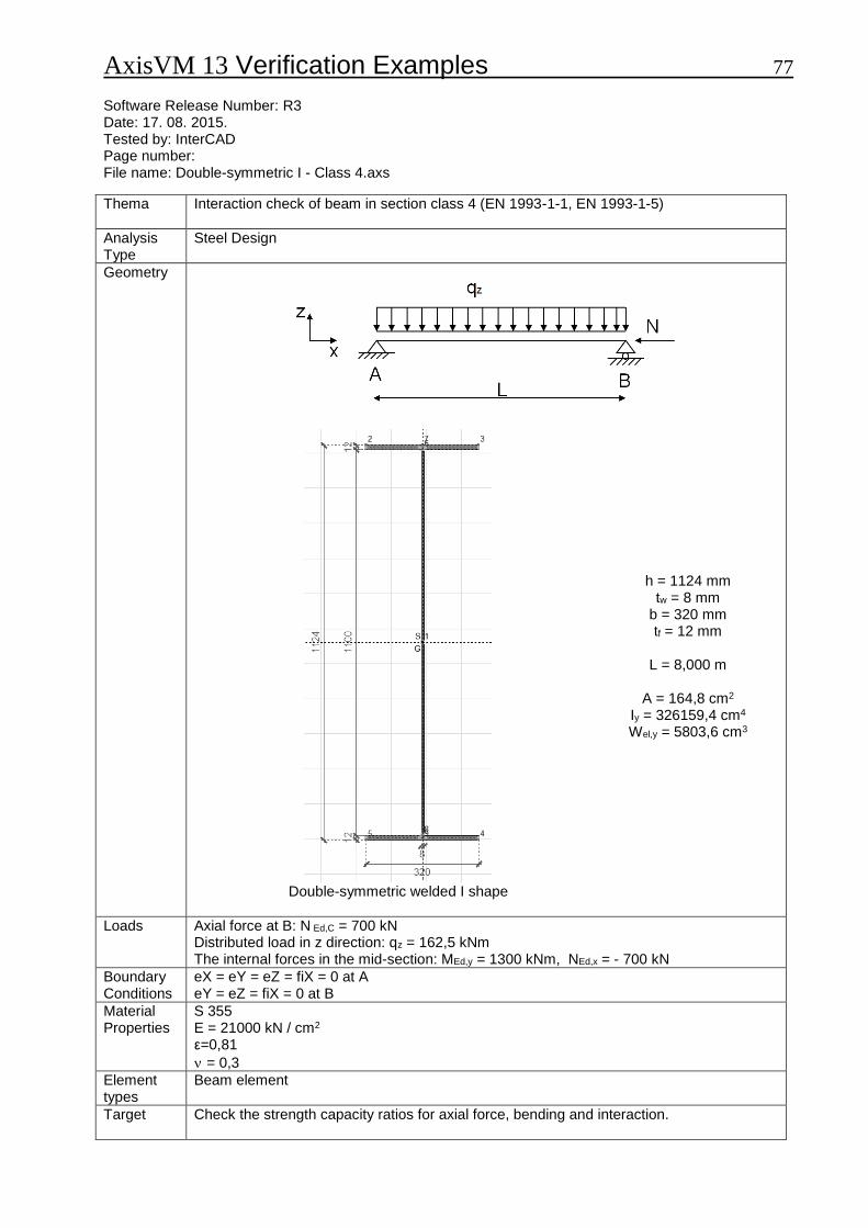
Thema
Interaction check of beam in section class 4 (EN 1993-1-1, EN 1993-1-5)
Analysis Type
Steel Design
Geometry
h = 1124 mm tw = 8 mm
b = 320 mm tf = 12 mm
L = 8,000 m
A = 164,8 cm2
Iy = 326159,4 cm4 Wel,y = 5803,6 cm3
Double-symmetric welded I shape
Loads
Axial force at B: N Ed,C = 700 kN Distributed load in z direction: qz = 162,5 kNm The internal forces in the mid-section: MEd,y = 1300 kNm, NEd,x = - 700 kN
Boundary Conditions
eX = eY = eZ = fiX = 0 at A eY = eZ = fiX = 0 at B
Material Properties
S 355 E = 21000 kN / cm2 ε=0,81
= 0,3
Element types
Beam element
Target
Check the strength capacity ratios for axial force, bending and interaction.

AxisVM 13 Verification Examples 78
Results Analytical solution in the following book: Dunai, L., Horváth, L., Kovács, N., Verőci, B., Vigh, L. G.: “Acélszerkezetek méretezése az Eurocode 3 alapján, Gyakorlati útmutató” (Design of steel structures according to Eurocode 3, ) Magyar Mérnök Kamara Tartószerkezeti tagozata, Budapest, 2009. Exercise 3.4., P. 14-16. Exercise 3.6., P. 19-21. Exercise 3.13., P. 34.
Analytical solution
AxisVM e [%]
Uniform compression
0,43 0,43 -
0,831 0,858 +3,1
0,931 0,910 -2,3
140,0 142,0 +1,4
4 4 -
2,957 2,975 +0,6
0,313 0,311 -0,6
340,8 342,4 +0,5
99,98 97,46 -2,6
3549 3460 +2,6
0,2 0,2 -
Uniform bending
0,43 0,43 -
0,831 0,858 +3,1
0,931 0,910 -2,3
139,95 142,0 +1,4
-0,969 -0,959 +1,0
23,09 22,84 -1,1
1,231 1,245 +1,1
0,739 0,731 -1,1
408,6 410,4 +0,4
5131 4976 -3,1
1821,5 1766,5 -3,1
0,71 0,74 +4,1
0,91 0,94 +3,3
Small differences occur because AxisVM does not take into account welding when calculating the effective section sizes.

AxisVM 13 Verification Examples 79
AxisVM 13 Verification Examples 80 Software Release Number: R3 Date: 17. 08. 2015. Tested by: InterCAD Page number: File name: Earthquake-01-EC.axs
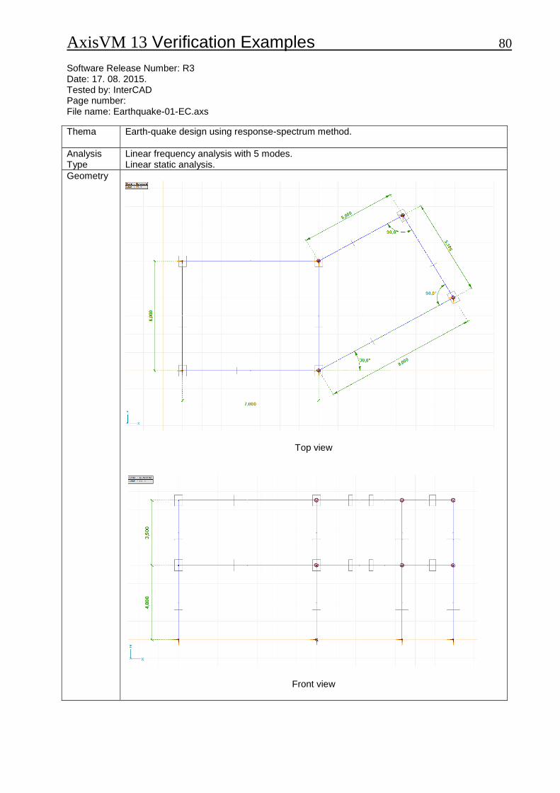
Thema
Earth-quake design using response-spectrum method.
Analysis Type
Linear frequency analysis with 5 modes. Linear static analysis.
Geometry
Top view
Front view
AxisVM 13 Verification Examples 81
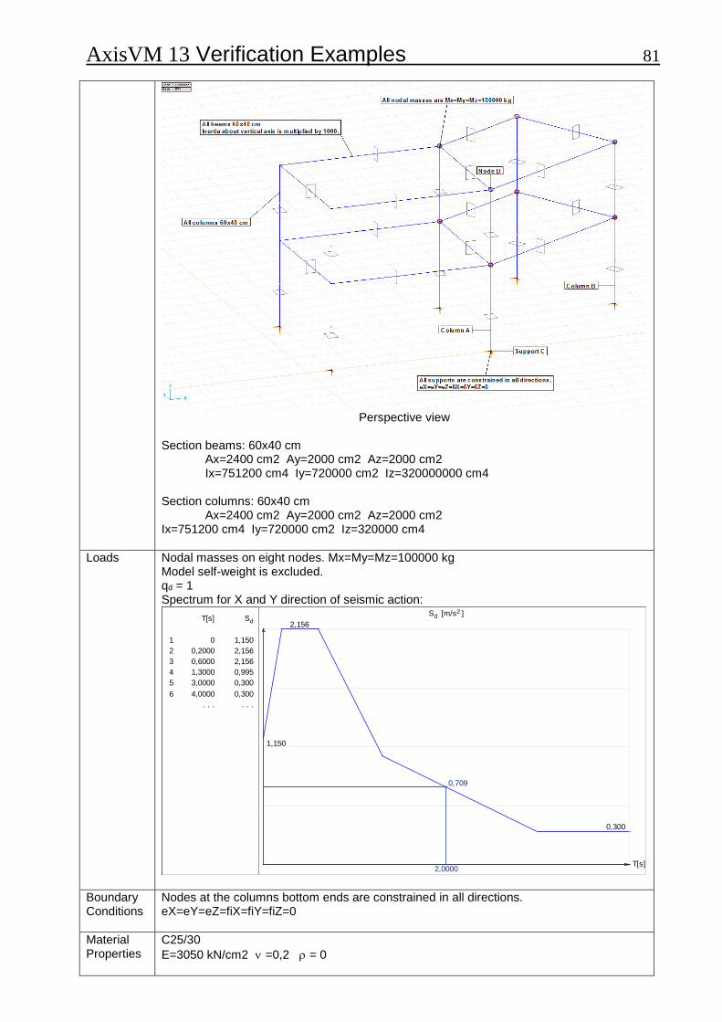
Perspective view
Section beams: 60x40 cm
Ax=2400 cm2 Ay=2000 cm2 Az=2000 cm2 Ix=751200 cm4 Iy=720000 cm2 Iz=320000000 cm4
Section columns: 60x40 cm
Ax=2400 cm2 Ay=2000 cm2 Az=2000 cm2 Ix=751200 cm4 Iy=720000 cm2 Iz=320000 cm4
Loads
Nodal masses on eight nodes. Mx=My=Mz=100000 kg Model self-weight is excluded. qd = 1 Spectrum for X and Y direction of seismic action:
Sd [m/s2 ]
T[s]
1,150
2,156
0,300
2,0000
0,709
T[s] Sd
1 0 1,150
2 0,2000 2,156
3 0,6000 2,156
4 1,3000 0,995
5 3,0000 0,300
6 4,0000 0,300
. . . . . .
Boundary Conditions
Nodes at the columns bottom ends are constrained in all directions. eX=eY=eZ=fiX=fiY=fiZ=0
Material Properties
C25/30
E=3050 kN/cm2 =0,2 = 0
AxisVM 13 Verification Examples 82
Element types
Rib element: Three node straight prismatic beam element. Shear deformation is taken into account.
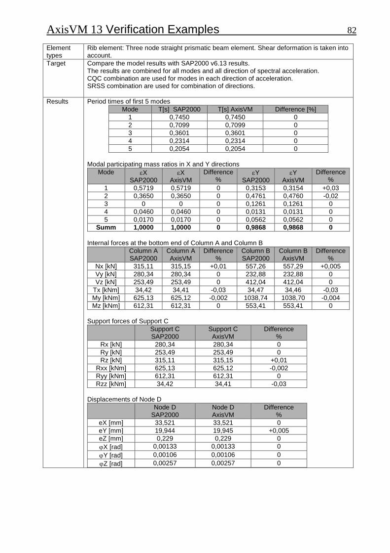
Target
Compare the model results with SAP2000 v6.13 results. The results are combined for all modes and all direction of spectral acceleration. CQC combination are used for modes in each direction of acceleration. SRSS combination are used for combination of directions.
Results
Period times of first 5 modes
Mode T[s] SAP2000 T[s] AxisVM Difference [%]
1 0,7450 0,7450 0
2 0,7099 0,7099 0
3 0,3601 0,3601 0
4 0,2314 0,2314 0
5 0,2054 0,2054 0
Modal participating mass ratios in X and Y directions
Mode X SAP2000
X AxisVM
Difference %
Y SAP2000
Y AxisVM
Difference %
1 0,5719 0,5719 0 0,3153 0,3154 +0,03
2 0,3650 0,3650 0 0,4761 0,4760 -0,02
3 0 0 0 0,1261 0,1261 0
4 0,0460 0,0460 0 0,0131 0,0131 0
5 0,0170 0,0170 0 0,0562 0,0562 0
Summ 1,0000 1,0000 0 0,9868 0,9868 0
Internal forces at the bottom end of Column A and Column B
Column A SAP2000
Column A AxisVM
Difference %
Column B SAP2000
Column B AxisVM
Difference %
Nx [kN] 315,11 315,15 +0,01 557,26 557,29 +0,005
Vy [kN] 280,34 280,34 0 232,88 232,88 0
Vz [kN] 253,49 253,49 0 412,04 412,04 0
Tx [kNm] 34,42 34,41 -0,03 34,47 34,46 -0,03
My [kNm] 625,13 625,12 -0,002 1038,74 1038,70 -0,004
Mz [kNm] 612,31 612,31 0 553,41 553,41 0
Support forces of Support C
Support C SAP2000
Support C AxisVM
Difference %
Rx [kN] 280,34 280,34 0
Ry [kN] 253,49 253,49 0
Rz [kN] 315,11 315,15 +0,01
Rxx [kNm] 625,13 625,12 -0,002
Ryy [kNm] 612,31 612,31 0
Rzz [kNm] 34,42 34,41 -0,03
Displacements of Node D
Node D SAP2000
Node D AxisVM
Difference %
eX [mm] 33,521 33,521 0
eY [mm] 19,944 19,945 +0,005
eZ [mm] 0,229 0,229 0
X [rad] 0,00133 0,00133 0
Y [rad] 0,00106 0,00106 0
Z [rad] 0,00257 0,00257 0
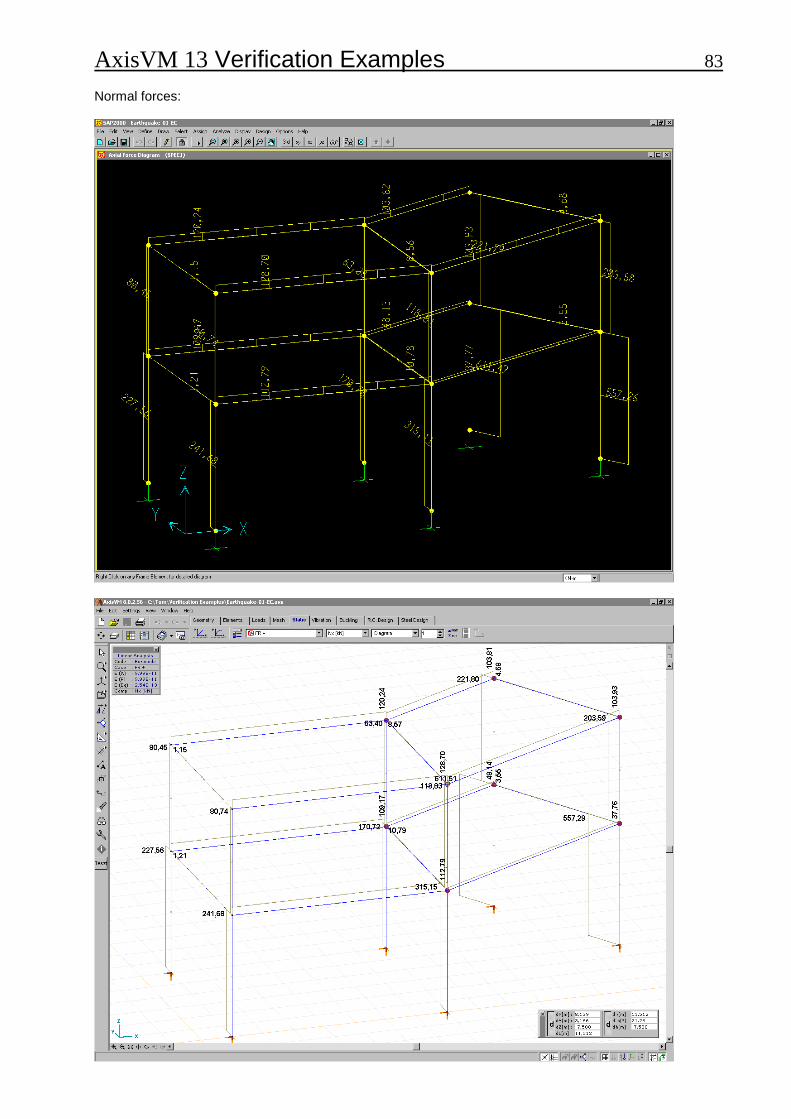
AxisVM 13 Verification Examples 83 Normal forces:

AxisVM 13 Verification Examples 84 Bending moments:
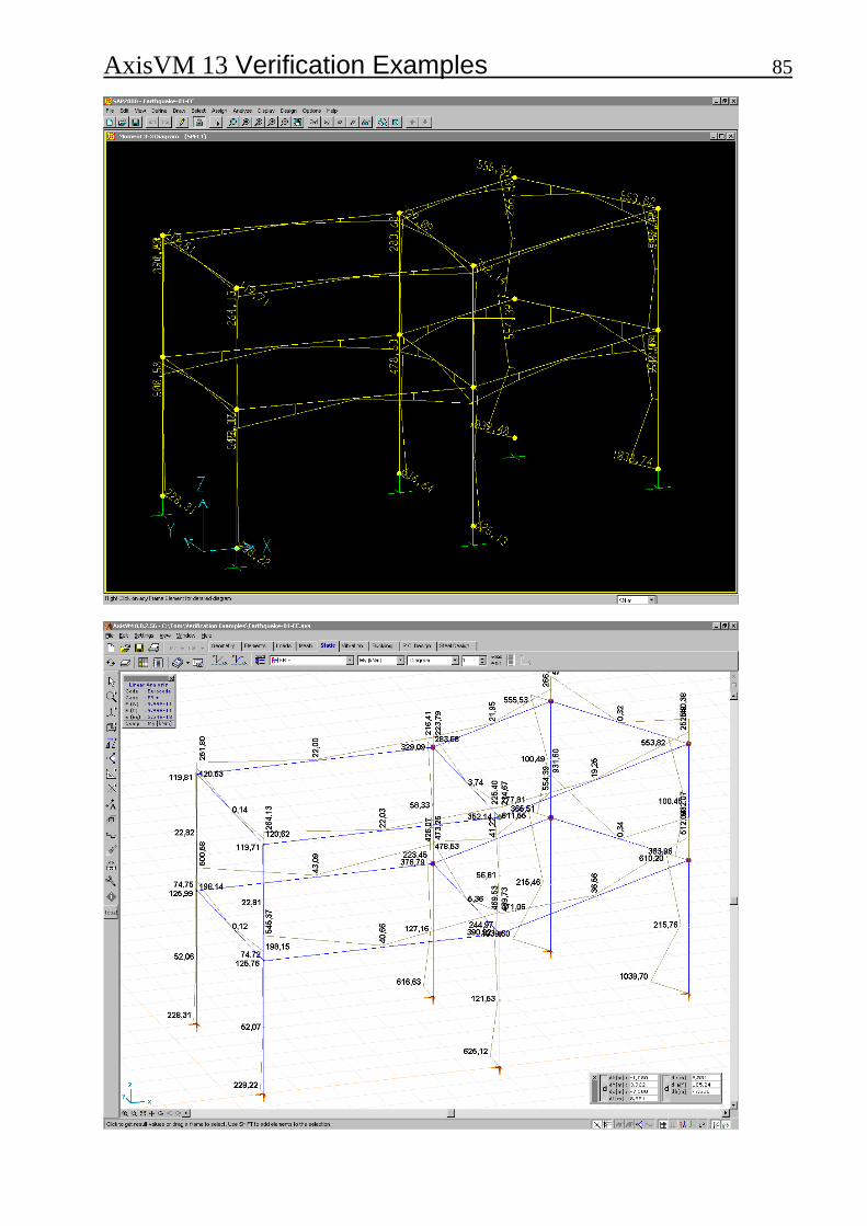
AxisVM 13 Verification Examples 85
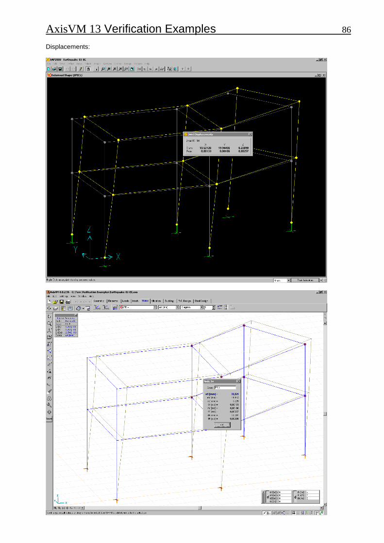
AxisVM 13 Verification Examples 86 Displacements:
AxisVM 13 Verification Examples 87 Software Release Number: R3 Date: 17. 08. 2015. Tested by: InterCAD Page number: File name: Plastic_1.axs
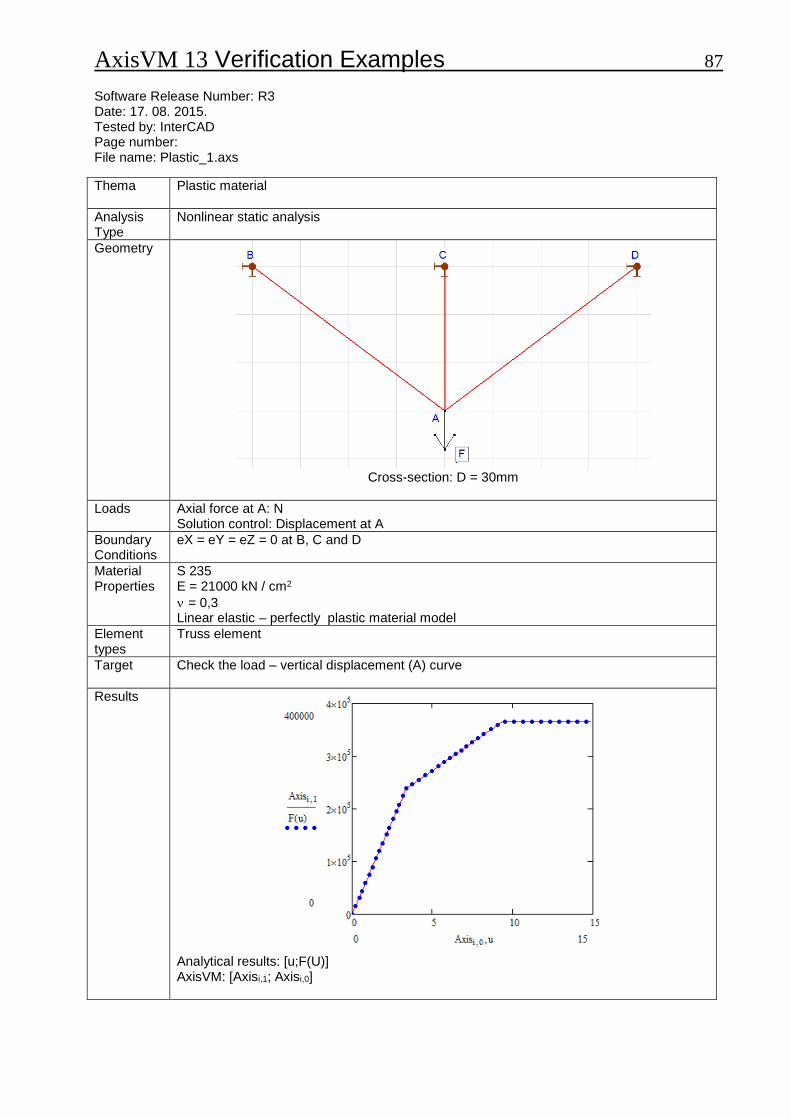
Thema
Plastic material
Analysis Type
Nonlinear static analysis
Geometry
Cross-section: D = 30mm
Loads
Axial force at A: N Solution control: Displacement at A
Boundary Conditions
eX = eY = eZ = 0 at B, C and D
Material Properties
S 235 E = 21000 kN / cm2
= 0,3 Linear elastic – perfectly plastic material model
Element types
Truss element
Target
Check the load – vertical displacement (A) curve
Results
Analytical results: [u;F(U)] AxisVM: [Axisi,1; Axisi,0]
AxisVM 13 Verification Examples 88 Software Release Number: R3 Date: 17. 08. 2015. Tested by: InterCAD Page number: File name: Plastic_1.axs
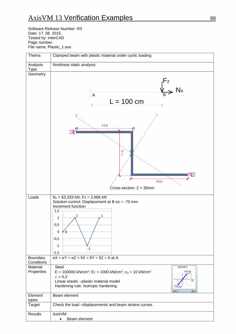
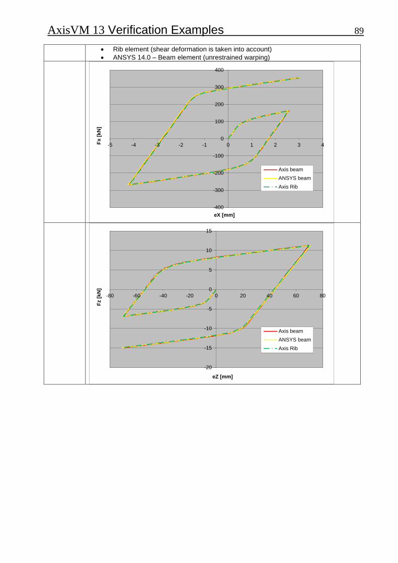
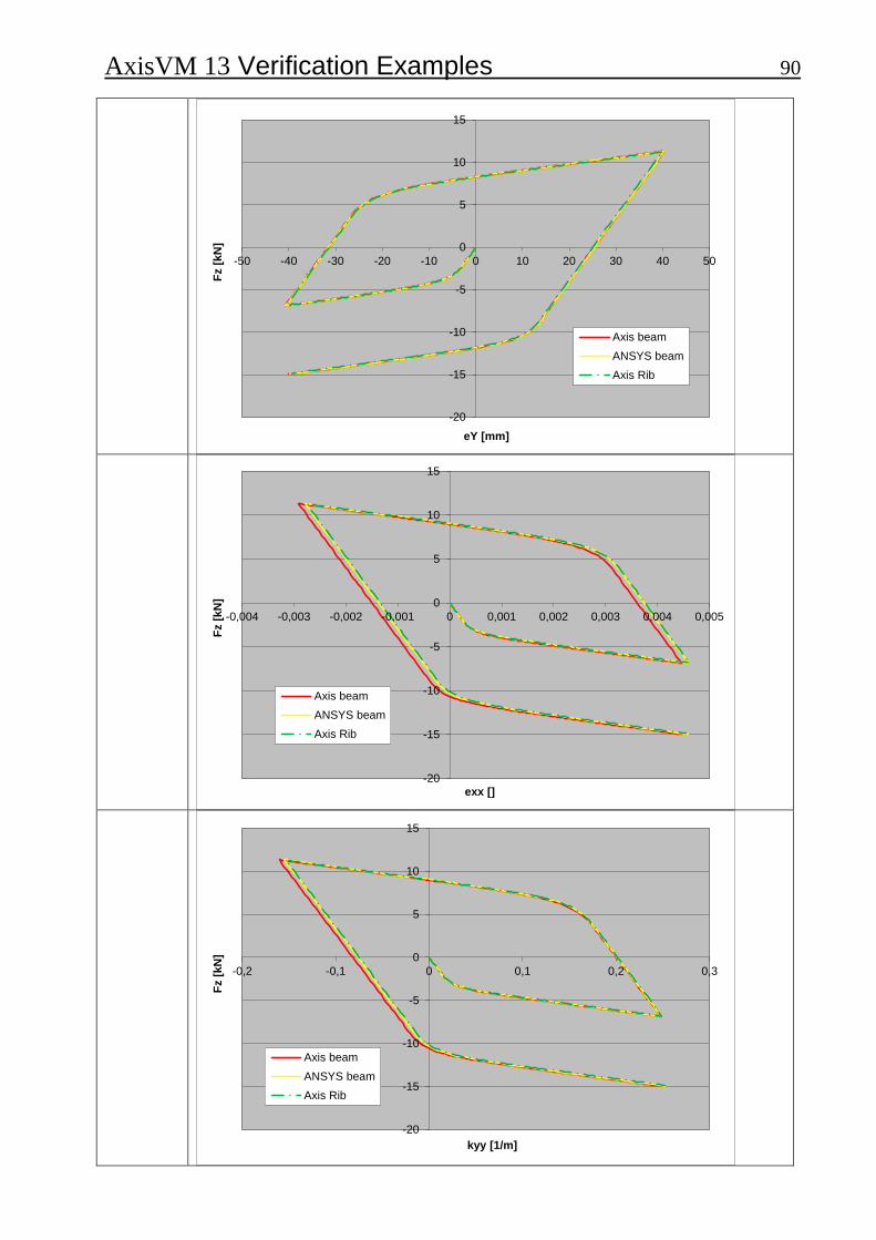
Thema
Clamped beam with plastic material under cyclic loading
Analysis Type
Nonlinear static analysis
Geometry Fz
Nx
L = 100 cmA B
Cross-section: Z = 30mm
Loads
Nx = 63,333 kN; Fz = 2,666 kN Solution control: Displacement at B ez = -70 mm Increment function:
0
1
-1
1
-1,5
-1
-0,5
0
0,5
1
1,5
Boundary Conditions
eX = eY = eZ = fiX = fiY = fiZ = 0 at A
Material Properties
Steel
E = 100000 kN/cm2; ET = 1000 kN/cm2; y = 10 kN/cm2
= 0,3 Linear elastic –plastic material model Hardening rule: Isotropic hardening
Element types
Beam element
Target
Check the load –displacements and beam strains curves
Results AxisVM:
Beam element
AxisVM 13 Verification Examples 89
Rib element (shear deformation is taken into account)
ANSYS 14.0 – Beam element (unrestrained warping)
-400
-300
-200
-100
0
100
200
300
400
-5 -4 -3 -2 -1 0 1 2 3 4Fx
[k
N]
eX [mm]
Axis beam
ANSYS beam
Axis Rib
-20
-15
-10
-5
0
5
10
15
-80 -60 -40 -20 0 20 40 60 80
Fz [
kN
]
eZ [mm]
Axis beam
ANSYS beam
Axis Rib
AxisVM 13 Verification Examples 90
-20
-15
-10
-5
0
5
10
15
-50 -40 -30 -20 -10 0 10 20 30 40 50
Fz [
kN
]
eY [mm]
Axis beam
ANSYS beam
Axis Rib
-20
-15
-10
-5
0
5
10
15
-0,004 -0,003 -0,002 -0,001 0 0,001 0,002 0,003 0,004 0,005
Fz [
kN
]
exx []
Axis beam
ANSYS beam
Axis Rib
-20
-15
-10
-5
0
5
10
15
-0,2 -0,1 0 0,1 0,2 0,3
Fz [
kN
]
kyy [1/m]
Axis beam
ANSYS beam
Axis Rib
![Design Patterns by Example for SystemVerilog Verification ... · PDF fileSystemVerilog Verification Environments Enabled by ... pattern examples: the Strategy Pattern [4] [5 ... Example](https://static.fdocuments.in/doc/165x107/5ab319097f8b9aea528df471/design-patterns-by-example-for-systemverilog-verification-verification-environments.jpg)