Verification and Validation of Roof Bolter Simulation ... · Verification and Validation of Roof...
14
Verification and Validation of Roof Bolter Simulation Models for Studying Events Between a Machine and its Operator John R. Bartels, Dean H. Ambrose and Richard C. Wang National Institute for Occupational Safety and Health (NIOSH), Pittsburgh Research Laboratory ABSTRACT This paper presents the results of a study to verify and validate a computer model that represents and analyzes motions and hazardous events in a simulated three- dimensional workplace. The purpose of the computer model is to support research that is investigating the safe speed range for the vertical movement of roof bolter boom arms to reduce worker injuries in underground coal mines. The information obtained for this paper is based upon a project that is investigating means to reduce workers risks of injury from exposure to mining machinery. The methodology being employed by the project includes human factors design considerations, anthropometric modeling and simulation tools, laboratory validation, engineering interventions, and collaboration with industry and an equipment manufacturer. The results of this study were used to (1) determine the input parameters that are unique to the mining environment and needed to develop a credible, computer-based, human-machine interactive model, (2) develop test methods to measure the required parameters, and (3) to refine the human-machine interactive computer model. INTRODUCTION PROBLEM There is currently no regulations or method of determining the safe speed of roof bolter boom arms. Three dimensional computer simulations provide machine designers and safety analysts with an accurate model for evaluating collision hazards concerning operator-machine interaction. Computer simulations of roof bolting tasks were conducted using bolter machine and bio-mechanical human models that ran on Unigraphics Solutions /Engineering Animation Incs JACK simulation software. Computer simulation allows multiple environments, virtual humans, and differing scenarios to be studied, which would be dangerous and time- and cost-prohibitive with field data studies. Before collecting final data, preliminary results of the roof bolter model need to be validated to ensure that parameter assumptions made for the computer-based simulation conform to actual field practice. This study verified operators response times, task motions, and field of view relative to the roof bolter boom arm. Human subjects tests with a full scale working mockup of a roof bolter boom arm were used for collecting motion data that helped determine parameters for building valid and credible models. BACKGROUND After miner crews in underground coal mines have cut a section of coal, roof bolter operators have the job of installing steel rods (bolts) into the mine roof to control cave-ins by securing sections of unsupported roof. Roof bolting may be regarded as a fairly structured and repetitive work situation. The entire bolting operation must be completed in a confined environment, for example, limited working height as low as 114.3-cm (45- in), in the vicinity of moving machinery (Figure 1). The problem becomes more pronounced the lower the seam height becomes. The confined environment requires the operator to work in awkward postures and to perform tasks requiring fast reaction times to avoid being hit by the moving machine appendages. Further compounding the problem is the low lighting conditions found in mines and the restricted visibility due to the protective canopy on the bolter machine. These conditions combine to make roof bolting one of the most dangerous occupations in underground mining. For the years 1992 through 1996, the Mine Safety and Health Administration (MSHA) injury database showed there was an average of 961 roof bolter operator accidents per year, representing 16% of all equipment related accidents, in underground coal mines. In order to address safety issues, a roof-bolter-machine committee was established by MSHA in 1994. The members of the committee were composed of MSHA, the West Virginia Board of Coal Mine Health and Safety, NIOSH, and roof bolter manufacturers. This committee studied 613 accidents that occurred during drilling and roof-bolt installation. The committee also looked at 15 fatalities attributed to inadvertent or incorrect actuation of the feed control lever, while the operator was within the drill head or boom arm pinch-point area. One outcome of this committees study was the realization that there was
Transcript of Verification and Validation of Roof Bolter Simulation ... · Verification and Validation of Roof...

Verification and Validation of Roof Bolter Simulation Modelsfor Studying Events Between a Machine and its Operator
John R. Bartels, Dean H. Ambrose and Richard C. WangNational Institute for Occupational Safety and Health (NIOSH),
Pittsburgh Research Laboratory
ABSTRACT
This paper presents the results of a study to verify andvalidate a computer model that represents and analyzesmotions and hazardous events in a simulated three-dimensional workplace. The purpose of the computermodel is to support research that is investigating the safespeed range for the vertical movement of roof bolterboom arms to reduce worker injuries in undergroundcoal mines. The information obtained for this paper isbased upon a project that is investigating means toreduce workers risks of injury from exposure to miningmachinery. The methodology being employed by theproject includes human factors design considerations,anthropometric modeling and simulation tools, laboratoryvalidation, engineering interventions, and collaborationwith industry and an equipment manufacturer. Theresults of this study were used to (1) determine the inputparameters that are unique to the mining environmentand needed to develop a credible, computer-based,human-machine interactive model, (2) develop testmethods to measure the required parameters, and (3) torefine the human-machine interactive computer model.
INTRODUCTION
PROBLEM
There is currently no regulations or method ofdetermining the safe speed of roof bolter boom arms.Three dimensional computer simulations providemachine designers and safety analysts with an accuratemodel for evaluating collision hazards concerningoperator-machine interaction. Computer simulations ofroof bolting tasks were conducted using bolter machineand bio-mechanical human models that ran onUnigraphics Solutions /Engineering Animation Inc�sJACK simulation software. Computer simulation allowsmultiple environments, virtual humans, and differingscenarios to be studied, which would be dangerous andtime- and cost-prohibitive with field data studies. Beforecollecting final data, preliminary results of the roof boltermodel need to be validated to ensure that parameterassumptions made for the computer-based simulationconform to actual field practice. This study verified
operators� response times, task motions, and field ofview relative to the roof bolter boom arm. Humansubjects tests with a full scale working mockup of a roofbolter boom arm were used for collecting motion datathat helped determine parameters for building valid andcredible models.
BACKGROUND
After miner crews in underground coal mines have cut asection of coal, roof bolter operators have the job ofinstalling steel rods (bolts) into the mine roof to controlcave-ins by securing sections of unsupported roof. Roofbolting may be regarded as a fairly structured andrepetitive work situation. The entire bolting operationmust be completed in a confined environment, forexample, limited working height as low as 114.3-cm (45-in), in the vicinity of moving machinery (Figure 1). Theproblem becomes more pronounced the lower the seamheight becomes. The confined environment requires theoperator to work in awkward postures and to performtasks requiring fast reaction times to avoid being hit bythe moving machine appendages. Further compoundingthe problem is the low lighting conditions found in minesand the restricted visibility due to the protective canopyon the bolter machine. These conditions combine tomake roof bolting one of the most dangerousoccupations in underground mining. For the years 1992through 1996, the Mine Safety and Health Administration(MSHA) injury database showed there was an average of961 roof bolter operator accidents per year, representing16% of all equipment related accidents, in undergroundcoal mines.
In order to address safety issues, a roof-bolter-machinecommittee was established by MSHA in 1994. Themembers of the committee were composed of MSHA,the West Virginia Board of Coal Mine Health and Safety,NIOSH, and roof bolter manufacturers. This committeestudied 613 accidents that occurred during drilling androof-bolt installation. The committee also looked at 15fatalities attributed to inadvertent or incorrect actuation ofthe feed control lever, while the operator was within thedrill head or boom arm pinch-point area. One outcome ofthis committee�s study was the realization that there was

no data on the safe speeds for roof bolter boomsoperating close to workers in a confined environment likean underground coal mine. Emphasis was placed onhazards related to the movement of the boom arm ormast of a roof-bolting machine. The committee�sobjective was to identify hazards and recommendsolutions. The data-collection effort consisted of analysisof: MSHA accident data; visits to underground mines andinterviews with experienced roof bolting machineoperators; discussions with roof bolting machinemanufacturers; interviews with workers injured whileperforming roof bolting tasks; and reviews of research onroof bolting safety. A set of recommendations toincrease the safety of roof bolting operations wasdeveloped, in particular, reduction of the bolter boomarm speed.
The main question that needs to be answered is whatrange of boom speeds minimizes the roof bolteroperators� chances of injury while still allowing the roofbolter operator to perform his job effectively. Thisquestion becomes even more important in light ofpotential rules proposed by MSHA on improving thedesign of roof bolters.
The information needed to answer this question is: 1)When does the operator see the boom arm and drillhead during the roof bolting operation? 2) Howfrequently are there collisions between the operator andthe roof bolter machine appendages? 3) What are thedistances between the operator�s hands, arms, legs andhead and the roof bolter�s boom arm and drill headduring each of the bolter operator�s job tasks? 4) Whatchanges do various operator postures, such as kneelingon one knee or two knees, make in these otherparameters?
In order to effectively answer these questions, asufficient number of studies must be conducted to collectcollision data that covers all of the variables. Laboratoryand field experiments examining these situations aredifficult because of the complexity and the instantaneousnature of the occurrences. Therefore, a computer-based, three dimensional solid object approach is beingused as the primary means to generate and collect thedata. Data collected in the roof bolter model consisted ofthe counting of mishaps. In the model, a mishap meanstwo or more objects intersecting; for example, the boomarm collides with the operator�s arm, hand or leg.Hazardous conditions were collected in three-dimensional computer environments using collisiondetection. Consequently, limited laboratory experimentswere needed to provide accurate parameters for the roofbolter model, and to validate the computer simulations.
The roof bolting operation was broken down into specifictasks. Klishis et al observed the tasks and the amount oftime spent on each task. [5] The task list provided aguide in developing the experimental design forlaboratory human subject tests and discrete movementscenarios for the computer simulations. This computer-based simulation was used to generate and collectcollision data between the machine and it�s operatorwhile recording many variables, such as the operator's
response times, operator postures, risk behaviors,anthropometry, and machine appendage velocity. Theroof bolter model evolved from code developed in Lispand Jack-Command-Language that creates randomhuman motions, random motion goals for the hands andtorso, and random motion of events reflecting operator'sbehavior.
The uncertainty or variability inherent in operatormovement required for the drilling and bolting tasks wasincorporated into the model to effectively determine thelikelihood of an operator being injured. In the modelrandom motion is generated, individual paths differedslightly even though the motions look very similar. Themodel incorporates variability in the motion and a pathvariance within that motion. Thus, for a machine andoperator, the operator's various risk behaviors, motionsfor each risk behavior, and motion paths associated witheach motion behavior, and moving machine appendageshave some degree of variability. These random motionsgive the model a realistic representation of the operator�smotions and behaviors found during the control of anyroof bolter task. A model that includes any randomaspects must involve sampling, or generating randomvariants. The phrase �generating a random variant"means to observe or realize a random variable fromsome desired arrangement of values of variablesshowing their observed or theoretical frequency ofoccurrence. To determine the range of thesedifferences, laboratory motion tests were conductedusing experienced roof bolter operators.
RESEARCH QUESTIONS ADDRESSED
1. Does the reduced lighting conditions in undergroundcoal mines reduce the optimum viewing area of aworker? Federal regulation requires illumination levelsaround a roof-bolting machine to be 0.06 fl (foot-Lambert). It is unknown if these lighting conditions willaffect the area in which an individual can detect amoving hazard. Optimum viewing areas in which roofbolt operators can detect moving hazards weremeasured, using standard optometrists� equipment,under normal lighting conditions and under mineillumination conditions
2. What is the whole body response time of anindividual performing bolting tasks in various posturesand various mine seam heights ranging from 114.3-cm(45-in) to 182.9-cm (72-in)? Due to the confinedenvironment of mining, the postures of bolter operatorsare unlike the postures of workers in other occupations.What effect does restricted space have on individualresponse times required to perceive and avoid hazards?When equipment operators detect a machine hazard,they want to get out of the way. In spite of awkwardpositions and postures imposed on operators by theirconfined environment, they require quick responses todangerous situations. To assist in the response timeinvestigation, operator motion was recorded, while theyavoided the moving appendages of the roof boltingmachine.

3. How well does the computer simulation of roof boltertasks match the actual movements of individuals (what isthe motion envelope for each of the bolting tasks)?
4. What is the operator�s position and orientation withrespect to the bolter�s controls and boom armappendage? The starting position of the operatordefines the movement envelope generated by thecomputer simulation for the virtual humans.
STUDY POPULATION
The study population for the computer simulation coversthe 5th through 95th percentile male. The study populationrepresents the target population, which is 99% male,however two female miners were among the studyvolunteers and were used to represent the 20th to 30th
percentile male operators due to the rarity of femaleoperators. Since the objective of the laboratory tests isnot to duplicate the entire simulation population, but onlyto verify that the simulation represents an accuratepicture of the real world, a small sample of 12 subjectswere tested. Movements of the virtual human will becompared to those of their test subject counterpart toevaluate the performance of the model. The optimumviewing area tests used 12 local subjects from NIOSH’sPittsburgh Research Laboratory (PRL) since no specialmining skill was involved. The response time and humanmotion data testing were conducted using 12 subjectsfrom the local office of the United Mine Workers ofAmerica (UMWA), which included two female volunteerswhich were included in the study, to accurately duplicatethe skills and experience involved in operating miningequipment. The anthropometrics for the 12 subjectsused in motion and response time studies are listed inTable 1.
DATA COLLECTION
Laboratory tests were performed on human subjects andthe results were used to compare laboratory andcomputer simulation results for basic input parameters tothe roof bolter model (Figure 2). Also, the optimalviewing area (vision cone) and human motion data wereused to evaluate the accuracy of the computersimulation. Operators� response times were used toquantify the effects of parameter values that are usedwith the computer simulation to determine occurrencesof collision and collision avoidance.
FIELD Of VISION IN REDUCED LIGHTING
For acceptable viewing in reduced lighting conditions,MSHA minimum lighting requirements mandatesillumination levels of 0.06 fl. Testing was required todetermine the viewing area, accurate field of vision andawareness of hazards with this background lighting anda cap lamp. Measurements were made using standardoptometrists� peripheral vision measuring equipment.Visual acuity was tested using Snellen charts. If subjectsnormally used glasses or contact lenses to correct theirvision, the subject wore these items during the vision
tests. Dependent measures included tests of peripheralvision (using a modified Peripheral Vision Chart), andvisual acuity (using Snellen eye charts).
Five tests were performed with each subject for both thevisual acuity and field of visions. Using normalprocedures for visual acuity testing, the subject wasseated 609.6-cm (240-in) away from the Snellen chartsand a standardized procedure was used to determine thesmallest row of letters that the subject could read underthe experimental conditions.
The five vision test conditions consist of a normal lightinglevel, a 0.06 fl level, 0.06 fl levels with a cap lamp, 0.03 fllevel, and 0.03 fl levels with a cap lamp. Test subjectswere asked to wear a standard hard hat and, for twotests, a hardhat and cap lamp. The test subjects wereplaced in a seated position. The background lighting wasadjusted to normal, 0.06 fl, 0.06 fl wearing a cap lamp,0.03 fl and 0.03 fl wearing a cap lamp. The subjects wereasked to place their head against a rest 60.96-cm (24-in)from a modified peripheral vision chart. Test subjectswere instructed to indicate when they detected themovement of a white ball under each of the threedifferent lighting conditions. Tests were conducted at 45degree increments above and below the horizontal plane(on both sides) and vertically from directly above thehead. The angle at which the subject becomes aware ofthe white ball in their field of vision was recorded for eachexperimental condition.
HUMAN RESPONSE IN ROOF BOLTING POSTURES
Human motion response times were measured for theoperator postures unique to operating a roof bolter.Appendix A describes the equipment constructed andused for this human subjects testing. Operator testpostures in 114.3-cm (45-in) and 152.4-cm (60-in) seamheights were performed with the operator kneeling,leaning forward with the head tilted to one side andlooking at a drilled hole location. The operator�s testposture in a 182.9-cm (72-in) seam height would be tostand if possible or hunch over to accommodate thestanding posture. The tests trials were repeated threetimes for each seam height and in the following postures:kneeling on one knee at a time and kneeling on bothknees. The tests were repeated for 182.9-cm seams in astanding or stooping posture. The human motions weremeasured and recorded using the motion trackingsystem. Appendix B describes the motion trackingsystem used in the laboratory tests.
Test subjects were asked to position themselves in a boltinsertion position with respect to the wooden mockuproof bolter. The right hand was situated on the boltercontrols and the left hand on the drill steel. The headwas above the boom, and the subject looked at the drillhole. At a given verbal signal, the test subjects wereinstructed to move themselves from the motion envelopeof the bolter boom (move from a forward leaning positionwith extended arms to a vertical position with armsresting at the side). The timing of the verbal cue wasrandom so that the subject was not able to anticipatewhen to start moving. For each experimental condition,

three repetitions of the test were performed. At least twominutes of rest was provided between repetitions. Thisinformation was used to determine if the simulatedhuman could have avoided a collision with the bolterboom. HUMAN MOTION ENVELOPS The human motion envelopes were measured for theoperator postures unique when operating the roof bolter.Operator test postures in 114.3-cm (45-in) and 152.4(60-in) seam heights were performed with the operatorkneeling posture either on one or two knees. Operator�stest posture in 182.9-cm (72-in) seam height would standif possible or hunch over to accommodate the standingposture. The subjects were supplied with standardmining safety equipment consisting of a hardhat,kneepads and safety glasses. The human motionenvelopes were measured and recorded using a motiontracking system. Test subjects were asked to position themselves in aspecified posture with respect to the working woodenmockup roof bolter. At a given signal they completed aroof bolting sequence. The specific roof bolting taskswere: insert drill steel, raise boom to drill hole, lowerboom and remove drill steel, put bolt (using a wrench ifneeded) in chuck, and raise boom to install bolt, torquebolt and lower the boom and remove wrench. Typically acomplete bolting sequence can be completed in 25 to 30seconds. The sequence was repeated three times ineach posture in each of the seam heights DATA ANALYSIS A randomized block experimental design was utilized forall phases of the study. Dependent measures in thisexperiment were analyzed using an Analysis of Variance(ANOVA), using a significance level of 95%, to determinewhether significant differences existed between theexperimental conditions. If the ANOVA indicated that asignificant difference existed, the Neuman-Keuls multiplerange test was used to identify those conditions wheresignificant differences existed. FIELD OF VISION IN REDUCED LIGHTING The results of analysis were averaged for the 12 subjectsand a vision area for the unique lighting conditions ofunderground mining environments was developed, whichaccounted for the use of a cap lamp and the reduction ofviewing area by the use of a standard hard hat. Theresults of the tests in 0.06fL lighting with a miner�s caplamp and hard hat were the most significant in terms ofinput to the simulation model. Typical results are shownin Table 2 and Figure 3.
The most significant reduction in a subject�s vision coneappeared to be a result of the reduction of the viewingarea caused by the hard hat. The rods of the eye, whichbecome more active in low light and allow night vision,were also the most sensitive to movement in the cone ofvision. The response of the eye rods was only slightlydiminished.
HUMAN RESPONSE IN ROOF BOLTING POSTURES Human response time is categorized by three discreteevents: (1) The recognition of the initialization signal; (2)the cognitive interpretation of the signal; and (3) theactual reaction. Since events 1 and 2 are welldocumented, our main concern was the response in theconfined and limiting mine environment, which had notbeen previously studied. Three trials were captured withthe motion tracking system. The operator reaction timeswere then averaged for each test subject. Summeryresults were obtained from Figure 4.
The data for the head and hands were considered themost significant for reaction characterization becausethese are the body parts most likely to be injured.Engineering parameters were calculated for thesesensors. Table 3 shows a sample of typical results.Average and maximum velocity and acceleration werecalculated for each of the sensors.
The range of variation is what one might expect fromhuman motion, maximum speed and accelerationincrease as the working space increased. When the datais viewed as a function of scale, the variations in reactionparameters were reasonable. This range was averagedby anthropometrical size, based on the National HealthExamination Survey [9], and used as the reactionresponse for the digital human model. The reaction timeof operators is significant when determining if anoperator will be able to avoid a moving object posing ahazard. HUMAN MOTION ENVELOPES In order to provide input parameters to the virtual humansimulation, the data from the motion tracking andcapturing system was divided into six discrete tasks: (1)loading the drill steel into the bolter arm; (2) drilling theroof; (3) lowering the bolter arm; (4) loading the roof boltinto the bolter arm; (5) bolting the roof; and (6) loweringthe bolter arm. The discrete points in the data wherethese particular events occurred were identified by thestart and stop points of a motion sensor mounted on thedrill boom). To identify these points, a graph of theacceleration of this sensor was overlaid on the graph ofthe boom movement. The points of maximumacceleration mark the start and stop points of the boom(Figure 5).
The motion data for each of the three trials by a singletest subject were then analyzed using ANOVA. Fortasks 2, 3, 5 and 6, the position of the moving boom wasused as the independent variable and the change in ascalar vector from the boom sensor to the body pointsensor being studied was used as the independentvariable. Standard deviations at each centimeter ofbolter boom movement were determined and themaximum standard deviation was selected as the seednumber for range of variability for the virtual humanmovement.
The data for tasks 1and 4 did not lend themselves to this

method of statistical analysis due the lack of a consistentindependent variable. These data were analyzed bytaking a standard deviation of the whole series of datapoints consisting of a scalar vector from the stationaryboom sensor. Since the data for these tasks is notcritical for the objective of the study (operator collisionswith a moving bolter arm), this was considered adequate.This data was then classified by anthropometrical sizefor incorporation into the model. Typical resultssummarized by anthropometrical size, seam height, andoperator postures are shown in a small example Table 4.
The results of motion variance analysis produced ascattered range of variation, which at first glance doesnot produce a consistent pattern. This range of variationwas small, when the data is viewed as a function ofscale, the variation in movement was reasonable for arepetitive task in a confined environment. The variationin motion also tended to increase as seam heightincreased providing increased working space. Thedifference in movement between tests ranged from 2 cmto 30 cm. This range is the seed number, which is closeto the originally assumed variance of motion used in thecomputer-based human model studies.
HUMAN-MACHINE INITIAL START POSTURE Using the HUMAN MOTION ENVELOP data, an averagestarting position for the subject�s knees and back sensorwas determined and a standard deviation for thesepoints determined. The results were then categorized bythe subject�s height position along the anthropometricalscale and averages obtained for 10 percentileincrements. Typical results are shown in Table 5.
Measurement locations of the back and knees providedinitial postures of the operator�s body relative to themachine. A value of �angle back Y�, i.e. 17.77, providesthe angle at which the body is to the boom arm. The�back X� value, -89.94-cm, provides a distance in thecoordinate X direction from the boom arm. Thisinformation provides the digital human model with arealistic starting position for the simulated boltingsequence and a valid range of variation in initial positionfor multiple simulation runs CONCLUSION
Equipment manufacturers require specific engineeringdata to provide ergonomically correct designs for workerprotection. Digital simulations provide a virtual operatorwith no limitations; the required tasks can be performedrepeatedly in infinite test scenarios. This allows thedesign parameters to be evaluated with out the need forextensive and potentially dangerous field studies.However, to provide valid models, adequate datadefining the human movement and variation ofmovement are required. This paper shows the methodsused to provide that input in to the unique environment ofunderground mining. The techniques used are alsoapplicable to a range of industrial applications. Themodel will still need to be verified once the parametershave been incorporated and the results compared to fieldand lab studies. The data obtained in these human
subject tests is also a database that will be used in theeventual validation of the final digital model.
ACKNOWLEDGMENTS
Bill Rossi and Ray Helinski provided technical support inoperating the motion tracking and data collection system.Mary Ellen Nelson, Al Cook, and Mary Ann Rossiassisted in the laboratory human subject tests. AugieKwitowski and Mike Pazuchanics helped with post dataprocessing. Joe DuCarme, Mary Ellen Nelson, Al Cook,George Fischer, Albert Brautigam provided technicalexpertise in the design and fabrication of the roof boltermockup and platform, and associated electrical andhydraulic control systems. Ergonomist for this work wereKim Cornelius and Sean Gallagher. All of the aboveassociates are employees of the National Institute forOccupational Safety and Health (NIOSH) at PittsburghResearch Laboratory, Pittsburgh, PA.
REFERENCES
1. Ambrose, D. H., �A Simulation Approach AnalyzingRandom Motion Events Between a Machine And itsOperator�. Proceedings of Society of AutomotiveEngineers Annual Meeting, 2000; paper number 2000-01-2160, pp. 11.
2. Etherton, J. "A Model of Human Reaction Time toDangerous Robot Arm Movements, NIOSH, Proceedingsof the Human Factors Society-31st Annual Meeting,"1987. pp. 231-235.
3. Goode, Kathryn T; Ball, Karlene K; Sloane, Michael;Roenker, Daniel L; Roth, David L; Myers, Renee S;Owsley, Cynthia. �Useful Field of View and otherneurocognitive indicators of crash risk in older adults�.Journal of Clinical Psychology in Medical Settings. Vol5(4), Dec 1998, pp. 425-440.
4. Kirk R.E., �Experimental Design: Procedures for thebehavioral sciences�, Brooks/Cole Publishing Company,Pacific Grove, CA, 1982.
5. Klishis, M. J., Althous, R. C., Layne, L. A., Lies, G.M.,�A Manual for Improving Safety in Roof Bolting�,Mining Extension Service, West Virginia University,1993,143 pp.
6. Klishis, M. J., et al, �Coal Mine Injury Analysis: AModel for Reduction Through Training�, MiningExtension Service, West Virginia University, 1993,220pp.
7. Kobrick, J. L. "Effects of Physical Location of VisualStimuli on Intentional Response Time�, Journal ofEngineering Psychology," 1965, pp. 1-8.
8. Lewis, W. H., �Underground Coal mining LightingHandbook�, US Bureau of Mines IC 9074,1986, 89 pp.

9. Staff of Anthropology Research Project,�Anthropometric Source Book Volume II: Handbook ofAnthropometric Data�, NASA Reference Publication1024, 1978, 421 pp.
10. Turin, F.C. �Human Factors Analysis of Roof BoltingHazards in Underground Coal Mines�, Bureau of MinesRI 9568, 1993, 25 pp.
11. Welford, A. T. "Reaction Time: Basic Concepts,"Academic Press, NY, NY, 1980, 418 pp.
12. Whitehead, K. L., “Mine Illumination”, US Bureau ofMines IC 8886, 1982, 337 pp.
APPENDIX A - MOCKUP ROOF BOLTER
A model of a typical roof bolter arm was constructedfrom wood, Figure 6. In all other respects, this modelresembled the actual equipment used underground. Itwas dimensionally identical and moved in the samemanner. The use of wood for the construction materialwas dictated by the requirement for the Flock of Birdsmotion tracking system, which is sensitive to ferrousmetals. The only metal parts in the model were somesmall pins and shafts at the articulating joints and thehydraulic cylinders.
The wooden bolter boom arm mockup has four hydraulicactuators; one each for boom rise, swing, sump andstabilizer jack. Normally, these actuators are pinned, orotherwise connected, at each end to transmit generatedforces to the structure. High pressure 175.75 kgf/cm2
(2,500 psi) was required in the hydraulic system in orderto provide the necessary flow and speed control.Although the actuators were of small diameter, they stillwere capable of generating high forces due to thispressure requirement. It was not feasible to monitor apressure rise resulting from an inadvertent contactbetween the test subject and the mockup. Such acontact would have resulted in a practically undetectablepressure change even though forces high enough tocause injury would be present. There fore a mechanicalmeans to limit the forces available from the mockup wasdevised. The hydraulic actuators on the bolter arm wereall assembled using a slip clutch connector, which limitsthe amount of force that the actuator can produce.These were adjusted and tested prior to any humansubjects testing to insure that they would perform asintended. If contact between the human subject and themoving bolter mockup should occur, the clutch slides onthe hydraulic actuator and prevents any injury. These slipclutches were installed on all of the hydraulic actuators inthe mockup.
The perimeter of the boom arm mockup was protectedfrom contact with the test subjects with a series of fivepairs of class 2 laser emitter diodes and sensors. Thissystem of sensors was connected to a fast dumphydraulic valve. Note that using the sensors to shut offthe hydraulic pump would have been ineffective becausethe pump would continue to produce flow until the motorhad coasted to a stop; this would have taken severalseconds. The use of a fast acting hydraulic dump valve
provided nearly instantaneous halt of the mockup�smotion. In the event of an operator coming close to themoving parts of the bolter mockup, the light curtain wouldbe broken. This would cause the dump valve to openand remove all hydraulic pressure, effectively stopping allmovement of the mockup. The electronic interfacebetween the laser sensors and the dump valve wasdesigned to �latch� a break in the sensors light beam.Thus, motion of the bolter mockup would not start againjust because the light beam became unobstructed.Once any of the sensors had been tripped, a reset switchhad to be depressed to reactivate the system hydraulics.The electronics interface had an indicator display thatshowed which of the sensors had been tripped. Thesesafety features also were tested extensively to insure theutmost in the human subject�s safety.
The final mechanical precaution was to construct thesimulated mine roof from suspended Styrofoam in theunlikely event that the test subject should contact or betrapped between the moving bolter arm and thesimulated roof. The lightweight Styrofoam would moveout of the way.
In order to assure safe operating speeds, the boom armspeed was limited to 55.88-cm/s (22-in/s) the maximumspeed that the roof bolter computer model is set. Normalbolter boom arm speeds can vary (i.e., 17.28- to 55.88-cm/s) depending on the size of the machines hydraulicpump. The hydraulic system for this mockup wasdesigned with flow adjustments on all actuators. Theseflow controls allowed each of the mockup�s actuatorspeeds to be controlled independently. The test speedwas set for 40.64 cm/s (16-in/s), the speed MSHA isconsidering as a regulated safe speed.
APPENDIX B - MOTION TRACKING AND DATACAPTURING SYSTEM
The structure of the UniGraphics Solutions-EngineeringAnimation Inc., JACK software makes it ideal for use withvirtual reality (VR) input and output devices. The use ofVR enables the user to become the virtual human figureand inhabit the virtual environment. VR features couldbecome very useful to build valid and credible simulationmodels. This is possible with the use of VR interfacesthat supports sensors, such as using Ascension Flock ofBirds with JACK software.
One of the best ways to model human movement is touse a real human to generate motion. The Flock of Birds(FOB) motion tracking system and JACK humanmodeling software provides these capabilities. Realistichuman movements can be recreated in real time usingposition and orientation information from the Flock ofBirds to drive the virtual human figure in a JACKsimulation environment. Using FOB�s sensorinformation, Jack�s MoCap module enables automaticanthropometrical scaling and storage of subjects and thecollection and recording of the subject�s motions.
The FOB is a six degree-of-freedom measuring devicethat can be configured to track the position andorientation of up to 60 sensors by the transmitter

simultaneously. Each sensor can make from 30 to 144measurements per second of its position and orientationwhen the sensor is found within 10 feet of its transmitter.Ascension provided PRL with a range of frequencies thatwould optimize a sensor�s sensitivity when trackingmotion around metallic objects. Tests were run on thebolter mockup around those areas containing metallicobjects. PRL�s investigators optimized the sensorsensitivity for the test conditions by setting them to 68.3measurements per second. The FOB determinesposition and orientation by transmitting a pulse DCmagnetic field that is simultaneously measured by allsensors in the Flock. From the measured magnetic fieldcharacteristics, each sensor independently computes itsposition and orientation and makes this informationavailable to a host computer. A FOB setup consisting ofmore than four sensors are configured into a Motion Starmodel.
The Motion Star model could consist of a chassis of upto 20 FOB sensors. PRL�s Motion Star system currentlyhas only 12 sensors. It takes a minimum of elevensensors to track the motion of a human adequately andthe twelfth defined the roof bolter boom arm (see Table6). Fasteners used by industry attach the sensor to eachwrist, elbow, knee, and foot, and to the neck, head andlower back (see figure 7). Because each sensor has itsown independent computer, the measurement rate isindependent of the number of sensors. The Ethernetinterface was used for FOB�s communication with a hostcomputer that ran JACK�s software module MoCap.
Table 1. Anthropometrics size of subjects
Subject Height, cm Weight, kg Age Gender Percentile Range
1 180.3 84.9 47 m 83.4 80-902 174.5 81.6 54 m 50.1 50-603 176.4 80.6 41 m 60.04 60-704 175.8 81.4 44 m 57.89 50-605 178.9 84.3 49 m 78.07 70-806 182.7 88 49 m 91.25 90-957 168.9 77 53 f 24.65① 20-308 168.7 76.4 47 f 24.30① 20-309 176.9 83.4 50 m 62.69 60-7010 182.4 89.9 47 m 90.13 90-9511 176.1 83 44 m 58.9 50-6012 173.4 79.3 48 m 48.91 40-50
① Male percentile used to categorize female subjectsBased on National Health Examination Survey9
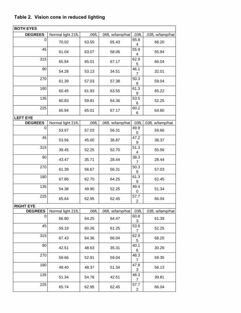
Table 2. Vision cone in reduced lighting
BOTH EYES
DEGREES Normal light 21fL .06fL .06fL w/lamp/hat .03fL .03fL w/lamp/hat0
70.02 63.55 65.4365.8
468.20
4561.04 63.07 58.06
55.94
55.94
31565.94 65.01 67.17
62.95
66.04
9054.28 53.13 34.51
46.17
32.01
27061.39 57.03 57.38
50.39
59.04
18060.45 61.93 63.55
61.39
65.22
13560.83 59.81 64.36
53.56
52.25
22565.94 65.01 67.17
60.26
64.80
LEFT EYE DEGREES Normal light 21fL .06fL .06fL w/lamp/hat .03fL .03fL w/lamp/hat
053.97 57.03 56.31
49.90
59.66
4553.56 45.00 36.87
47.29
38.37
31539.45 52.25 52.70
51.34
55.56
9043.47 35.71 28.44
38.37
28.44
27061.39 56.67 56.31
50.39
57.03
18067.86 62.70 64.25
61.39
62.45
13554.38 49.90 52.25
49.40
51.34
22565.64 62.95 62.45
57.72
66.04
RIGHT EYE DEGREES Normal light 21fL .06fL .06fL w/lamp/hat .03fL .03fL w/lamp/hat
066.80 64.25 64.47
60.83
61.39
4559.19 60.26 61.25
53.97
52.25
31567.43 64.36 66.04
62.95
68.20
9042.51 48.63 35.31
40.16
30.26
27059.66 52.91 59.04
48.37
59.35
18049.40 48.37 51.34
47.83
56.13
13551.34 54.78 42.51
48.37
39.81
22565.74 62.95 62.45
57.72
66.04

Table 3. Example of operator reaction parameters in a 114.3-cm (45-in) seam height
Subject PositionMaximumSpeed of
Head, cm/sec
Elapsed Time,sec (*)
MaximumAcceleration,
cm/sec2
AverageSpeed,cm/sec
Head Left Hand Right Hand Head Left Hand Right Hand6 Both Knees 39.18 0.667 392.91 973.04 120.88 26.91 37.61 4.25 Left Knee 23.19 0.411 332.70 493.99 626.46 16.40 21.02 22.70 Right Knee 32.76 0.667 394.30 679.48 72.98 24.42 16.84 2.53
10 Both Knees 60.67 0.622 749.18 2978.87 272.38 33.34 53.47 13.04 Left Knee 97.90 0.733 1438.55 2029.96 533.81 49.61 69.82 17.28 Right Knee 101.75 0.944 1796.46 1678.98 1609.13 54.10 31.36 24.03
(*) Time to Reach Maximum Speed of Head
Table 4. Standard deviation of motion 50th - 60th percentile in a 114.3-cm (45-in) seam height
TASK NO Std DevHEAD (cm)
Std Dev LEFTHAND (cm)
Std Dev RIGHTHAND (cm)
1 Insert Drill 5.57 12.27 13.442 Drill Roof 3.68 9.20 2.593 Lower Boom 2.93 16.02 2.874 Insert Bolt 4.49 13.54 21.385 Bolt Roof 2.09 5.12 3.29
Both Knees
6 Lower Boom 2.56 8.43 5.591 Insert Drill 6.03 12.05 17.042 Drill Roof 3.48 13.91 12.643 Lower Boom 3.22 8.45 13.524 Insert Bolt 5.67 12.74 23.935 Bolt Roof 3.83 15.51 11.16
Left Knee
6 Lower Boom 4.23 3.98 10.531 Insert Drill 5.40 6.49 6.182 Drill Roof 4.09 7.15 28.063 Lower Boom 6.11 18.52 14.844 Insert Bolt 8.23 11.28 16.125 Bolt Roof 3.22 6.50 3.77
Right Knee
6 Lower Boom 4.71 6.44 3.27

Table 5. Starting position for 114.3-cm (45-in) seam height on both knees for 50th-60th percentile
Mean (cm) StandardDeviation (cm)
Distance Back 93.08 7.06Distance Neck 81.11 17.53
Distance Left Knee 48.06 17.22Distance Right Knee 60.77 14.22
BACK X -89.94 2.24BACK Y 60.14 9.18BACK Z 240.54 2.28
Angle Back X -94.47 2.87Angle Back Y 17.77 6.04Angle Back Z 97.72 5.45
NECK X -52.94 4.78NECK Y 97.01 10.07NECK Z 238.28 5.71
Angel Neck X -99.41 17.19Angel Neck Y 63.84 5.39Angel Neck Z 106.17 23.91
Left Knee X -48.20 2.31Left Knee Y 26.43 7.25Left Knee Z 215.63 3.61
Angel Left Knee X 99.66 3.43Angel Left Knee Y 30.07 5.27Angel Left Knee Z -100.58 13.31
Right Knee X -42.17 2.83Right Knee Y 25.64 7.35Right Knee Z 247.56 3.53
Angel Left Knee X 86.84 5.84Angel Left Knee Y 28.27 2.62Angel Left Knee Z -104.78 3.58
Table 6 � Sensor locationsSensor Location
1 Head2 Waist3 Neck4 Left Elbow5 Right Elbow6 Left Wrist7 Right Wrist8 Left Knee9 Right Knee10 Left Foot11 Right Foot12 Boom Arm

Figure 1 Roof Bolter Operator in Low Seam
Figure 2. Vision cone in the roof bolter model

Figure 3. Vision cone in degrees

Figure 4. Head reaction in three trialsHEAD REACTION
115120125130135
0 5 10 15 20
Time, seconds
Dis
tanc
e, c
m
Figure 5. Determination of task starting points
0.00100.00200.00300.00400.00500.00600.00700.00800.00
time
2.27
4.53
6.80
9.07
11.3
3
13.6
0
15.8
7
18.1
3
20.4
0
22.6
7
BoomAcceleration
Figure 6. Roof bolter boom arm mockup

Figure 7. Sensor locations on subject