
Verification and Validation of Nek5000 for T-Junction ...
12
Verification and Validation of Nek5000 for T-junction, Matis, SIBERIA, and Max Experiments. Aleksandr Obabko 1 , Paul Fischer 1,2 , Oana Marin 1 , Elia Merzari 1,3 , and Dave Pointer 4 1 : Mathematics and Computer Science Division, Argonne National Laboratory, 9700 S Cass Ave., Argonne, IL 60439, USA 2 : Department of Mechanical Science and Engineering and Department of Computer Science, University of Illinois at Urbana-Champaign, IL 60439, USA 3 : Nuclear Engineering Division, Argonne National Laboratory, 9700 S Cass Ave., Argonne, IL 60439, USA 4 : Reactor and Nuclear Systems Division, Oak Ridge National Laboratory, Oak Ridge, TN 37831, USA ABSTRACT The turbulent mixing modeling for unsteady heat transfer problems in thermal-hydraulics has long been a focus in nuclear engineering community. One of the promising approaches that takes a full advantage of recent advances in HPC is the use of hierarchy of fidelity simulations that are cross-verified and validated in the regimes of interest. In particular, it is beneficial to have a higher fidelity reference simulation that could be used for benchmarking of the faster-turn-around lower-fidelity tools. This paper focuses on Nek5000 LES reference simulations for the OECD/NEA T-junction and Matis benchmarks and for the “SIBERIA” and MAX con-current validation experiments. The CFD capabilities to predict the unsteady heat transfer problems that are associated with non- isothermal flow mixing in pipe flows and related to thermal fatigue of nuclear power plant pipe system have been tested in the 2010 Vattenfall T-junction benchmark. The 2012 KAERI Matis experiment has tested the CFD predictions in a complex geometry of subchannel mixing flow behind a spacer grid. The Nek5000 LES submissions scored highly in the both blind benchmarks. The Novosibirsk’s “SIBERIA” experiment employs a novel electrochemical technique for accurate measurement of the wall mean shear and its fluctuations in an annular channel flow with a blockage. The ANL’s MAX experiment is designed to study thermal mixing in a wide mixing chamber where two out of a maximum of four adjacent differentially heated jets are injected to impinge on the top wall surface, leading to a thermal striping phenomenon. The resulting complex flow configuration is tracked by a high-resolution particle velocimetry method and thermal imaging. The high-quality benchmark data profiles and high-resolution MAX data provided are used for validating numerical simulation capabilities of Nek5000 for these types of flows and for benchmarking and improvement of lower-fidelity uRANS modeling as a part of hierarchical multi-fidelity approach. KEYWORDS LES, CFD, thermal striping, turbulent mixing, spacer grid 1. INTRODUCTION Recent advances in HPC enable the use of hierarchy of fidelity simulations that are cross-verified and validated in the regimes of interest for the prediction of turbulent mixing modeling in unsteady heat transfer problems relevant to nuclear engineering community. In particular, it is beneficial to have a higher-fidelity thermal-hydraulics (TH) capability for producing a reference simulation that could be used 1462 NURETH-16, Chicago, IL, August 30-September 4, 2015 1462 NURETH-16, Chicago, IL, August 30-September 4, 2015
Transcript of Verification and Validation of Nek5000 for T-Junction ...

Verification and Validation of Nek5000 for T-junction, Matis, SIBERIA, and
Max Experiments.
Aleksandr Obabko1, Paul Fischer1,2, Oana Marin1, Elia Merzari1,3, and Dave Pointer 4 1: Mathematics and Computer Science Division, Argonne National Laboratory, 9700 S Cass
Ave., Argonne, IL 60439, USA 2: Department of Mechanical Science and Engineering and Department of Computer Science,
University of Illinois at Urbana-Champaign, IL 60439, USA 3: Nuclear Engineering Division, Argonne National Laboratory, 9700 S Cass Ave., Argonne, IL
60439, USA 4: Reactor and Nuclear Systems Division, Oak Ridge National Laboratory, Oak Ridge, TN
37831, USA ABSTRACT
The turbulent mixing modeling for unsteady heat transfer problems in thermal-hydraulics has long been a focus in nuclear engineering community. One of the promising approaches that takes a full advantage of recent advances in HPC is the use of hierarchy of fidelity simulations that are cross-verified and validated in the regimes of interest. In particular, it is beneficial to have a higher fidelity reference simulation that could be used for benchmarking of the faster-turn-around lower-fidelity tools. This paper focuses on Nek5000 LES reference simulations for the OECD/NEA T-junction and Matis benchmarks and for the “SIBERIA” and MAX con-current validation experiments.
The CFD capabilities to predict the unsteady heat transfer problems that are associated with non-isothermal flow mixing in pipe flows and related to thermal fatigue of nuclear power plant pipe system have been tested in the 2010 Vattenfall T-junction benchmark. The 2012 KAERI Matis experiment has tested the CFD predictions in a complex geometry of subchannel mixing flow behind a spacer grid. The Nek5000 LES submissions scored highly in the both blind benchmarks. The Novosibirsk’s “SIBERIA” experiment employs a novel electrochemical technique for accurate measurement of the wall mean shear and its fluctuations in an annular channel flow with a blockage. The ANL’s MAX experiment is designed to study thermal mixing in a wide mixing chamber where two out of a maximum of four adjacent differentially heated jets are injected to impinge on the top wall surface, leading to a thermal striping phenomenon. The resulting complex flow configuration is tracked by a high-resolution particle velocimetry method and thermal imaging.
The high-quality benchmark data profiles and high-resolution MAX data provided are used for validating numerical simulation capabilities of Nek5000 for these types of flows and for benchmarking and improvement of lower-fidelity uRANS modeling as a part of hierarchical multi-fidelity approach.
KEYWORDS LES, CFD, thermal striping, turbulent mixing, spacer grid
1. INTRODUCTION
Recent advances in HPC enable the use of hierarchy of fidelity simulations that are cross-verified and validated in the regimes of interest for the prediction of turbulent mixing modeling in unsteady heat transfer problems relevant to nuclear engineering community. In particular, it is beneficial to have a higher-fidelity thermal-hydraulics (TH) capability for producing a reference simulation that could be used
1462NURETH-16, Chicago, IL, August 30-September 4, 2015 1462NURETH-16, Chicago, IL, August 30-September 4, 2015

for benchmarking and improvement of the faster-turn-around lower-fidelity tools. This paper focuses on Nek5000 large-eddy simulation (LES) benchmarks and reference simulations for a variety of the OECD/NEA exercises and con-current experiments.
Nek5000 is an open-source highly-scalable CFD solver and NEAMS* toolkit’s TH module based on the spectral-element method (SEM), a high-order weighted residual technique that combines the geometric flexibility of the finite-element method with the tensor-product efficiencies of spectral methods. Recently it has been used in a variety simulations to gain unprecedented insight into the physics of turbulence in complex flows. Nek5000 results scored highly in the blind OECD benchmarks of Vattenfall T-Junction and KAERI Matis experiments. Flow in a T-junction is one of the examples of unsteady heat transfer problems that are associated with non-isothermal flow mixing in pipe flows. They have long been the topic of concern in the nuclear engineering community because of the relation to thermal fatigue of nuclear power plant pipe systems. When turbulent flow streams of different velocity and density rapidly mix at the right angle, a contact interface between the two mixing streams oscillates and breaks down because of hydrodynamic instabilities, and large-scale unsteady flow structures emerge. If the mixing flow streams are of different temperatures, the hydrodynamic oscillations are accompanied by thermal fluctuations on the pipe wall. The resulting thermal striping accelerates thermal-mechanical fatigue, damage the pipe structure and, ultimately, cause its failure. Associated with large-scale anisotropic mixing, thermal striping is notorious to predict with lower-fidelity modeling tools based on time-averaging approaches, such as Reynolds-averaged Navier-Stokes (RANS) models, are badly suited. Consequently, one must consider unsteady modeling methods such as unsteady RANS (uRANS) or LES that is most generic and does not assume the existence of a spectral gap between the large and the small scales as uRANS does. On the other hand, owing to recent advances in computing, LES methods are becoming an increasingly affordable tool as petascale architectures become more accessible.
The T-junction benchmark exercise highlighted an importance of con-current simulation and experiment campaign where additional follow-up measurements and simulations could be easily conducted to resolve any arising or ambiguous features. Here we report initial validation results and reference simulations in two experiments, namely annular channel flow with blockage “SIBERIA” in Novosibirsk and high-resolution turbulent mixing chambers with hexagonal inlets MAX experiment in ANL. The latter is designed to study thermal mixing in a wide mixing chamber where two out of a maximum of four adjacent differentially heated jets are injected to impinge on the top wall surface, leading to a thermal striping phenomenon. The resulting complex flow configuration is tracked by a high-resolution particle velocimetry method and thermal imaging. The high-resolution data provided could be used for validating numerical simulation capabilities of CFD codes. Here we focus on the initial higher-fidelity LES simulations with Nek5000 for MAX geometry and its use as a reference simulation for lower-fidelity modeling.
This work illustrates an important role of the high-fidelity simulations in benchmarking the lower-fidelity turbulence modeling approaches in TH reinforcing the concept of the hierarchical multi-fidelity simulations adopted in NEAMS. Figure 1 shows a schematic representation of the full hierarchy of TH codes in NEAMS TH toolkit of which we focus mostly on Nek5000 LES verification and validation in addition to its use to produce a reference simulation for lower-fidelity RANS and uRANS modeling. 2. Nek5000
The proposed method has been implemented in the Argonne-based open source fluid/thermal simulation code Nek5000 [1, 2], which has been designed specifically for transitional and turbulent flows in complex domains. Nek5000 is based on the spectral-element method (SEM) [3], a high-order weighted residual technique that combines the geometric flexibility of finite elements with the rapid convergence and tensor-product efficiencies of global spectral methods. Globally, the SEM is based on a * Nuclear Energy Advanced Modeling and Simulation
1463NURETH-16, Chicago, IL, August 30-September 4, 2015 1463NURETH-16, Chicago, IL, August 30-September 4, 2015

decomposition of the domain into E smaller subdomains (elements), which are assumed to be curvilinear hexahedra (bricks) that conform to the domain boundaries. Locally, functions within each element are expanded as Nth-order polynomials cast in tensor-product form, which allows differential operators on N3 gridpoints per element to be evaluated with only O(N4) work and O(N3) storage. The principal advantage of the spectral-element method is that convergence is exponential in N, which implies that significantly fewer degrees of freedom (DOF) per wavelength are required to accurately propagate a signal (or turbulent structure) over the extended times associated with advection-dominated flow simulations at high Reynolds numbers.
a) b)
Figure 1. (a) Hierarchical structure of NEAMS TH tools; (b) volume rendering of instantaneous temperature distribution from T-junction simulation†
In addition to its high-order foundation, Nek5000 has several other features that make it ideally suited for large-scale parallel simulations. Temporal discretization is based on a high-order splitting that is third-order accurate in time and reduces the coupled velocity-pressure Stokes problem to independent three Helmholtz and one elliptic solver per time step, i.e. for each velocity component and pressure, respectively. The velocity problems are diagonally dominant and thus easily solved by using Jacobi-preconditioned conjugate gradient iteration. The pressure substep requires a Poisson solve at each step, which is performed through multigrid-preconditioned GMRES iteration coupled with temporal projection to find an optimal initial guess. Particularly important components of Nek5000 are its scalable coarse-grid solvers that are central to parallel multigrid. The code features a fast direct solver that is optimal up to processor counts of P ≈ 104 and a fast algebraic multigrid solver for P = 105 and beyond. Counts of 15 GMRES iterations per time step for billion-gridpoint problems are typical with the current pressure solver for a good quality mesh. Nek5000 scales extremely well on the IBM BG/P and BG/Q architectures [5]. Time stepping is usually performed by using a characteristic scheme [4]. 3. T-Junction
In this section, we compare the results of the Nek5000 LES codes produced for the 2010 OECD/NEA/IAEA T-junction Vattenfall benchmark problem. The geometry specifications of the could be found in [5]. Volume rendering of instantaneous temperature distribution in Figure 1b shows the geometry and the large-scale mixing structure developing downstream of the cold branch (blue). Run at Re=40,000 based on diameter of the cold branch D=14 cm, the Nek5000 results submitted to the blind benchmark received #1 score in prediction of temperature. The spectral element mesh had 62,000 elements with polynomial order N=7 resulting in 21 million DOF.
† Acknowledge the assistance from Hank Childs with VisIt
1464NURETH-16, Chicago, IL, August 30-September 4, 2015 1464NURETH-16, Chicago, IL, August 30-September 4, 2015

a) b) Figure 2. T-junction vertical profiles at x/D=0.6 (magenta), 1.6 (black), 2.6 (blue), 3.6 (green),
4.6 (red) for the experimental data (symbols) and Nek5000 simulation with N = 5 (dashed) and N = 7 (solid) and for Nek5000 benchmark submission results (dash-dotted). (a) Axial mean velocity; (b) axial rms velocity.
Figure 2a and 2b show the vertical profiles of the mean and rms axial velocity profiles at x=0.6 (magenta), 1.6 (black), 2.6 (blue), 3.6 (green), and 4.6 (red) with N=5 (dashed) and N=7 (solid). Note that the axis of the hot branch is at x=0. The benchmark submission results (i.e., with N=7 and shorter time average) plotted with dash-dotted line at x=1.6...4.6 are in the excellent agreement with the longer time average run (solid). All profiles agree well with the experimental data points (symbols), especially considering the fact that the Reynolds number of these simulations, Re=40,000 was two times less than that of the experiment in order to speed up the computations. In general, the profiles from the coarse mesh simulation (i.e., N=5, dashed) are close to the solution for the finer mesh (solid and dash-dotted lines) but even larger resolution runs are preferable especially at the experiment Re value. Note the excellent agreement between the profiles for N=5 and N=7 at x=0.6 that we added the list of plotted profiles to illustrate the extent of the reversed flow region. The latter was a primary focus of the international cross-verification and validation study with our IBRAE‡ [5]. The success with LES predictions of T-junction geometry allows us to use this reference simulation for benchmarking against the current lower-fidelity but faster turn-around tools and to improve them. To this regard we have developed, implemented and started testing an improved version of RANS model, regularized k-omega model [6]. This benchmark exercise also highlighted an importance of con-current simulations and experiments when additional follow-up measurements and simulations could be easily conducted to deal with any arising or contentious features like an extent of the recirculation region in this benchmark.
4. Matis
The 2012 KAERI Matis experiment has tested the CFD predictions in the complex geometry of subchannel mixing flow behind a spacer grid. Nek5000 results submitted for the blind benchmark were
‡ Moscow Institute of Nuclear Energy Safety
1465NURETH-16, Chicago, IL, August 30-September 4, 2015 1465NURETH-16, Chicago, IL, August 30-September 4, 2015
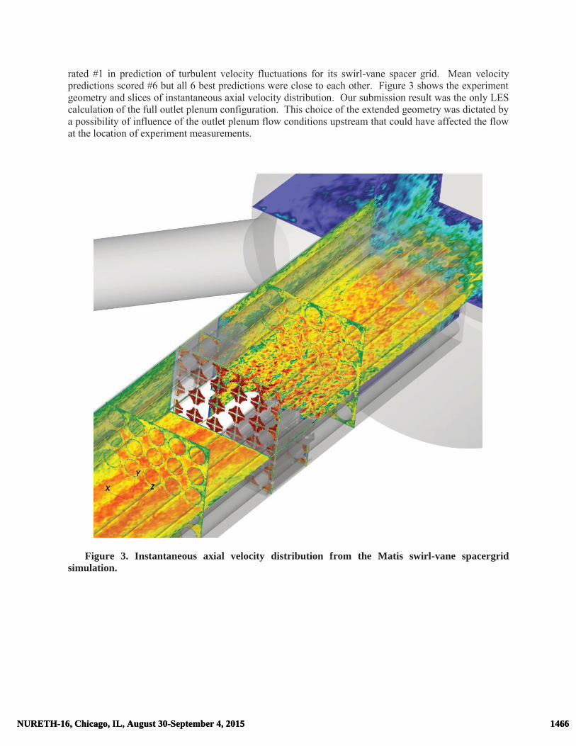
rated #1 in prediction of turbulent velocity fluctuations for its swirl-vane spacer grid. Mean velocity predictions scored #6 but all 6 best predictions were close to each other. Figure 3 shows the experiment geometry and slices of instantaneous axial velocity distribution. Our submission result was the only LES calculation of the full outlet plenum configuration. This choice of the extended geometry was dictated by a possibility of influence of the outlet plenum flow conditions upstream that could have affected the flow at the location of experiment measurements.
Figure 3. Instantaneous axial velocity distribution from the Matis swirl-vane spacergrid simulation.
1466NURETH-16, Chicago, IL, August 30-September 4, 2015 1466NURETH-16, Chicago, IL, August 30-September 4, 2015

a) b) Figure 4. Matis horizontal profiles of axial velocity at z/Dh=0.5 distance from the swirl-vane
spacer for Nek5000 LES (red) and Star-CCM+ uRANS (magenta) simulations along with two other cross-verification participants from IBRAE. (a) Mean axial velocity; (b) rms axial velocity.
The computational mesh has 700,000 elements with the polynomial degree up to N=7 and up to 240 million DOF. Recycling technique similar to T-junction simulation has been developed for fully developed turbulent flow upstream of the spacer using a novel approach based on interpolation. Figure 4a and 4b shows the horizontal profiles of axial velocity at z/Dh=0.5 distance from the swirl-vane spacer for Nek5000 LES (red) and Star-CCM+ uRANS (magenta) simulations. More details on the simulation and the follow-up cross-verification and validation study with IBRAE could be found in [7].
In accordance with our TH hierarchical multi-fidelity strategy, the use of Nek5000 LES results as a reference simulation assisted the benchmarking of uRANS models and chose of more adequate model for this benchmark, namely ID-DES. Its application to the split-vane spacergrid case geometry resulted in a benchmark prediction that scored among first 5 top simulations.
a) b) Figure 5. Velocity magnitude distribution in simulations of “SIBERIA” geometry. (a) Volume
rendering of instantaneous field; (b) slices of mean field.
1467NURETH-16, Chicago, IL, August 30-September 4, 2015 1467NURETH-16, Chicago, IL, August 30-September 4, 2015

5. “SIBERIA”
The Novosibirsk experiment “SIBERIA” studies a simple physical model of rod bundle flow, i.e. flow in the axisymmetric annular channel with a blockage [8]. The uniqueness of the experiment setup is its capability to accurately measure the mean wall shear and its fluctuations with a novel electrochemical technique. Other advantages of the experiment are that it has a potential to become a con-current validation experiment and be upgraded to handle two-phase flows.
With 20,000 spectral elements and up to 24 million DOF, the initial Nek5000 simulations were conducted for laminar flow inlet conditions. Figure 5a shows an unsteadiness of separation behind the obstacle in volume rendering of instantaneous velocity magnitude field. The blockage and associated low-velocity region of a three-dimensional recirculation bubble is clearly visible in slices of mean velocity magnitude (Figure 5b). Next step is to check the influence of upstream turbulence on the solution with a help of recycling boundary condition technique and prepare data for future comparison with experiment. 6. MAX
The ANL MAX experiment [9,10] aims at providing data needed for high-resolution and fidelity validation in the context of thermal striping phenomena. It comprises a 1 m x 1 m x 1.68 m test section and support for one to four hexagonal canister inlets with air jets of varying temperature and velocity. The present section focuses on LES of the MAX experiment under different inlet geometry. The initial simulations are purely hydrodynamic with no inclusion of buoyancy modeling at this stage. Only cases considering two hex canisters out of four total have been simulated.
Despite the hydrodynamic simplification, the results show that flow inside the mixing chamber is highly sensitive to geometric shape of hex inlets inside the domain. In particular, two types of geometry configurations have been simulated. The first type (labeled MAX1 hereafter) presents a protrusion of the two hexagonal duct canisters inside the test chamber whereas the second type (MAX2) does not include any protrusion and the hex outlet are flush with the bottom of the mixing chamber. Figure 6a and 6b show the spectral element mesh for the MAX1 (with protrusion of Dh=13.6 cm) and MAX2 (flush) cases, correspondingly. Both meshes have about 70,000 spectral elements that correspond to up to 24 million DOF with the polynomial order up to N=7. Time integration is performed with a nondimensional timestep as low as 8.25e-4 using both a fourth-order-accurate Runge-Kutta characteristic method and a third-order backward-difference multistep method with extrapolation for nonlinear terms (BDF3/EXT3). Similar to T-junction and Matis simulations, the flow in the inlets is modeled as fully-developed turbulent flow in a hexagonal duct by imposing recycling boundary conditions over a periodic length of 4.8 and 5.0 Dh for the left and right inlet, respectively. At all walls, no-slip conditions apply; and the outlet is modeled by using a nozzle outflow condition where velocity divergence is increasing as parabola from zero in the last layer of elements adjacent to the outlet that proved to produce excellent results in T-junction blind benchmark. As in the latter, the LES spectral damping was used with parabolic modal filtering of up to 5% for the two last modes. The LES simulations are run at Reynolds numbers of Re=8,700…20,000 based on the inlet bulk velocity of 100 cm/s and the hexagonal duct flat-to-flat distance of Dh=13.6 cm. For all simulations here, we focus on results at Re=20,000 unless stated otherwise.
The instantaneous field of vertical velocity Vz depicted in Figure 7 exhibits different behavior for the MAX1 (left) and MAX2 (right) geometry configurations. The extrusion of the hexagonal duct inlets into the mixing chamber stabilizes the vertical jets emanating from the inlets in MAX1 case while the flushing the duct inlets with the bottom of the mixing chamber in the MAX2 setup cause the jets to wobble and to collapse occasionally.
1468NURETH-16, Chicago, IL, August 30-September 4, 2015 1468NURETH-16, Chicago, IL, August 30-September 4, 2015

a) b)
Figure 6. Nek5000 spectral element mesh for the MAX geometry computation. (a) MAX1 setup (with protrusion); (b) MAX2 configuration (flush).
a) b)
Figure 7. Instantaneous vertical velocity field slices for the MAX experiment. (a) MAX1 setup; (b) MAX2 geometry. Analysis of the mean velocity magnitude V fields for both inlet configurations in Figure 8 suggests the possible culprit for the unstable behavior. The horizontal slice of V at z=20 cm shows a noticeable vortex shedding behind the hexagonal duct inlets in the cross-flow of the MAX2 configuration. Presumably this interaction between the jets and cross-flow leads to the destabilization of the jets further downstream in the MAX2 case while the protrusion of MAX1 inlets shields the jet from it.
1469NURETH-16, Chicago, IL, August 30-September 4, 2015 1469NURETH-16, Chicago, IL, August 30-September 4, 2015

a) b) Figure 8. Mean velocity magnitude field slices for the MAX experiment. (a) MAX1 setup; (b)
MAX2 geometry. One consequence of the destabilization of jets is the enhanced momentum mixing in the MAX2 case as compared to MAX1. A manifestation of the enhancement is observed further downstream of the jets including a distinct topological signature in the horizontal flow along the upper surface of the mixing chamber. More stable case of MAX1 flow results in the persistent recirculation region near the upper surface visualized in Figure 9a at $z=98 cm$ (2 cm away) with the bright green line of zero x-component of velocity Vx above the inlets at x=2 and y=0 while MAX2 flow pattern is simpler and does not exhibit this region (Figure 9b).
a) b) Figure 9. Contours of mean horizontal velocity components near the upper surface of the MAX
experiment geometry at z=98 cm. (a) MAX1 setup; (b) MAX2 configuration. Further analysis of the Vx profiles across the recirculation region near the upper wall in Figure 10 shows a similar behavior for both configuration. However, the enhanced mixing of MAX2 case results into a smoother profile (dashed green line) eliminating the two additional points of Vx=0 present in the MAX1 case (red solid line). First comparison of the simulation results agrees well with preliminary experiment data but more con-current experiment and simulation work is needed. In particular, we have started the development, implementation and testing the synthetic eddy method for simulating the grid-like turbulent
1470NURETH-16, Chicago, IL, August 30-September 4, 2015 1470NURETH-16, Chicago, IL, August 30-September 4, 2015

inlet conditions that will have a closer match with experiment profiles in the hexagonal ducts. Another note is that MAX1 configuration was easily accessibly with steady state runs while MAX2 case presented a challenge for lower-fidelity approach that was overcome after comparison with the reference LES simulation whose cost and complexity was no different than that of MAX1. Here again we successfully demonstrated an applicability of the adopted hierarchical approach. Also this exercise shows that unlike the lower-fidelity approaches, the validated higher fidelity modeling is less susceptible to the geometry and parameter perturbations.
Figure 10. Horizontal component Vx near the upper surface of the MAX1 setup (red solid line)
and MAX2 configuration (green dashed line). Lastly, we have reported a series of computations in a regime of transition from laminar to turbulent flows in order to access a feasibility of experiment data acquisition there. The results of Nek5000 LES simulations with buoyancy effects in Boussinesq approximation have qualitatively agreed with experiment and help to conclude that it is infeasible to access the laminar and transition regime without a major experiment upgrade. Figure 11 shows a volume rendering and a slice of instantaneous temperature at two time snapshots of one of these MAX1 simulations at Re=300. 7. CONCLUSIONS
Responding to the challenges of turbulent mixing modeling for unsteady heat transfer problems in thermal-hydraulics (TH), we have developed and successfully used a hierarchy of multi-fidelity modeling. In particular, we focus here on verification and validation of Nek5000 LES approach for variety of benchmark and problems and con-current experiments. The results with this open-source highly-scalable CFD code and TH module of NEAMS toolkit scored highly in OECD/NEA blind benchmarks of Vattenfall T-junction and KAERI Matis spacergrid. We also report initial validation results and reference simulations in two experiments, namely annular channel flow with blockage “SIBERIA” in Novosibirsk and high-resolution turbulent mixing chambers with hexagonal inlets MAX experiment in ANL. In particular, the initial validation results compared with preliminary experiment data confirm that unlike the
1471NURETH-16, Chicago, IL, August 30-September 4, 2015 1471NURETH-16, Chicago, IL, August 30-September 4, 2015

lower-fidelity approaches, the validated higher fidelity modeling is less susceptible to the geometry and parameter perturbations. It could also be used as a reference simulation for benchmarking and improvement of lower-fidelity but faster-turn-around modeling tools.
a) b)
Figure 11. Volume rendering and slice of instantaneous temperature at two time snapshots of the MAX1 simulation with buoyancy effects at Re=300. Early (a) and later (b) time.
This work used resources of the DOE Office of Science User Facility ALCF (Argonne Leadership
Computing Facility) and was funded under the auspices of the Nuclear Energy Advanced Modeling and Simulation (NEAMS) program of the U.S. Department of Energy Office of Nuclear Energy.
The submitted manuscript has been created by UChicago Argonne, LLC, Operator of Argonne National Laboratory (``Argonne''). Argonne, a U.S. Department of Energy Office of Science laboratory, is operated under Contract No. DE-AC02-06CH11357. The U.S. Government retains for itself, and others acting on its behalf, a paid-up nonexclusive, irrevocable worldwide license in said article to reproduce, prepare derivative works, distribute copies to the public, and perform publicly and display publicly, by or on behalf of the Government. REFERENCES
1. P. Fischer et al, Nek5000 website. https://nek5000.mcs.anl.gov (2014) 2. P. F. Fischer, J. Lottes, W. D. Pointer, and A. Siegel, “Petascale algorithms for reactor
hydrodynamics.” Journal of Physics Conference Series (2008). 3. Y. Maday, A. T. Patera, and E. M. Ronquist, “An operator-integration-factor splitting method for
time-dependent problems: Application to incompressible fluid flow.” Journal of Scientific Computing, 5, pp. 263–292 (2009).
4. P. Fischer, “Implementation considerations for the OIFS/characteristics approach to convection problems.” http://www.mcs.anl.gov/~fischer/nek5000/oifs.pdf
5. A. V. Obabko, P. F. Fischer, T. J. Tautges, V. M. Goloviznin, M. A. Zaytsev, V. V. Chudanov, V. A., Pervichko, A. E. Aksenova, and S. Karabasov, “Large Eddy Simulation of Thermo-Hydraulic Mixing in a T-Junction.” In Donna Guillen, editor, “Nuclear Reactor Thermal Hydraulics and Other Applications” (2012).
6. A. Tomboulides, S. M. Aithal, P. F. Fischer, E. Merzari and A. Obabko, “A Novel Variant of the K-ω URANS Model for Spectral Element Methods: Implementation, Verification, and Validation
1472NURETH-16, Chicago, IL, August 30-September 4, 2015 1472NURETH-16, Chicago, IL, August 30-September 4, 2015

in Nek5000.” FEDSM2014-21926, ASME 2014 4th Joint US-European Fluids Engineering Division Summer Meeting, Chicago, Illinois, USA, August 3–7 (2014).
7. A. V. Obabko, A. E. Aksenova, V. V. Chudanov, P. F. Fischer, V.M. Goloviznin, A.A. Kanaev, S. Karabasov, E. Merzari, S. Parker, V. A. Pervichko, W. D. Pointer, T. Taugets, M. A. Zaytsev, "Cross-verification and validation simulations of Matis benchmark." ANL/TM-341, (2015).
8. O. N. Kashinsky, P. D. Lobanov, A. S. Kurdyumov and N. A. Pribaturin, “Heat Transfer and Turbulent Structure in an Annular Channel With an Obstacle.” FEDSM2014-21482, ASME 2014 4th Joint US-European Fluids Engineering Division Summer Meeting, Chicago, Illinois, USA, August 3–7 (2014).
9. W. D. Pointer, S. Lomperski, and P. Fischer, “Validation of CFD methods for advanced SFR design: upper plenum thermal striping and stratification.” In ICONE17 (2009).
10. S. Lomperski and D. Pointer, “Max CFD validation data set for twin isothermal jets.” ANL-NE-12/42, (2012).
1473NURETH-16, Chicago, IL, August 30-September 4, 2015 1473NURETH-16, Chicago, IL, August 30-September 4, 2015