VERAVIEW 2D MORITA
20
Veraviewepocs ® 2D – High Speed Panoramic X-Ray Crystal Clear Images with Reduced Radiation Thinking ahead. Focused on life.
description
VERAVIEW 2D MORITA
Transcript of VERAVIEW 2D MORITA

Veraviewepocs® 2D – High Speed Panoramic X-RayCrystal Clear Images with Reduced Radiation
Thinking ahead. Focused on life.

Thinking ahead. Focused on life.

Thinking ahead. Focused on life.

High Speed, Digital Panoramic/Cephalometric 7.4 Second Panoramic, 4.9 Second Cephalometric
The Veraviewepocs 2D features new, cutting edge technology that delivers extremely high quality images with low X-ray exposure.
This unit also offers a variety of specialized programs, such as the Orthoradial Panoramic projection, which reduces the overlapping of neighboring teeth, and the Shadow Reduction Panoramic projection, which reduces obstructing shadows. In addition, the AF function offers easy and accurate patient positioning.
The high definition, refined image processing system offers multiplanar observation – enabling accurate diagnosis and analysis.
Veraviewepocs 2D is also completely upgradeable to the Veraviewepocs 3D model.
Highlights at a Glance
Digital Panoramic
Fine High Speed Mode features 7.4 second exposure time, n1/4 X-ray exposure*
High quality images using both Digital Direct Automatic nExposure (DDAE) and Automatic Image Enhancer (AIE)
High resolution images even in Fine High Speed Mode n
Easy patient positioning with AF automatic positioning, triple nlaser beams, and power assisted movement
No film or film development necessary n
Digital Cephalometric
High speed, 4.9 second exposure time, n1/10 X-ray exposure*
More diagnostic information – greater dynamic range n
Image processing can be completed within 20 seconds n
Fully automatic settings for easy operation n
No film or film development necessary n
* This comparison is made with the Veraviewepocs film-based system
4
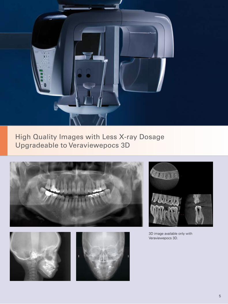
High Quality Images with Less X-ray DosageUpgradeable to Veraviewepocs 3D
3D image available only with Veraviewepocs 3D.
5

Super High QualityDigital Panoramic Images
Super High Quality Image – The Veraviewepocs offers high resolution even in Fine High Speed Mode. With superb density and contrast, Digital Direct Automatic Exposure (DDAE), and Automatic Image Enhancer, Veraviewepocs always obtains an optimal image.
High Resolution
Fine High Speed Mode: Pixel size is reduced by 25% compared to the previous model, so it produces superior images of a higher resolution.
Super Fine Mode: Produces an even better im-age with increased resolution.
Fine High Speed Mode: pixel size 144 μm Super Fine Mode: pixel size 96 μm
Panoramic Cassette
The high resolution CCD sensor (32-bit microprocessor) produces high quality, digital, panoramic images.
6

Super High QualityDigital Panoramic Images
CCD Sensor X-ray head
kVmA
Computer
Digital Direct Automatic Exposure (DDAE)
DDAE controls the X-ray tube voltage (kV) and current (mA) simultaneously by detecting X-rays passing through the patient. This improves the dynamic range, and along with Automatic Ex-posure (AE), results in exceptionally clear images with the best possible contrast and even density. The Automatic Exposure level can be adjusted to meet individual requirements.
There is no need to set the tube voltage and current. DDAE guarantees the optimum tube voltage (60 to 80 kV) and current (1 to 10 mA). (Voltage and current may also be set manually.)
Automatic Image Enhancer comparison
Conventional Image
Automatic Image Enhancer (AIE)
Automatic Image Enhancer enhances the details that can be observed in areas which are either extremely white or extremely black. DDAE and AIE perform a logarithmic con-version to produce the highest quality image possible.
7
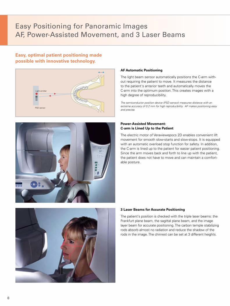
PSD sensor
Light emitter
AF Automatic Positioning
The light beam sensor automatically positions the C-arm with-out requiring the patient to move. It measures the distance to the patient's anterior teeth and automatically moves the C-arm into the optimum position. This creates images with a high degree of reproducibility.
Power-Assisted Movement: C-arm is Lined Up to the Patient
The electric motor of Veraviewepocs 2D enables convenient lift movement for smooth slow-starts and slow-stops. It is equipped with an automatic overload stop function for safety. In addition, the C-arm is lined up to the patient for easier patient positioning. Since the arm moves back and forth to line up with the patient, the patient does not have to move and can maintain a comfort-able posture.
3 Laser Beams for Accurate Positioning
The patient‘s position is checked with the triple laser beams: the Frankfurt plane beam, the sagittal plane beam, and the image layer beam for accurate positioning. The carbon temple stabilizing rods absorb almost no radiation and reduce the shadow of the rods in the image. The chinrest can be set at 3 different heights.
Easy Positioning for Panoramic ImagesAF, Power-Assisted Movement, and 3 Laser Beams
Easy, optimal patient positioning made possible with innovative technology.
The semiconductor position device (PSD sensor) measures distance with an extreme accuracy of 0.2 mm for high reproducibility. AF makes positioning easy and precise.
8

Consistent Magnification with Versatile Projections and Wheelchair Support
Multiple projections fit a variety of purposes.Consistent magnification is maintained throughout the image.
Shadow Reduction PanoramicOrthoradial PanoramicStandard Panoramic
The Veraviewepocs 2D Has Various Projections
The distance from the X-ray tube to the patient is consistent, providing uniform magnification. The overlapping of neighboring teeth or the shadow of the opposing mandibular ramus is reduced, providing optimal results for jaw exposures.
Wheelchair Support
The Veraviewepocs 2D offers a width of up to 18.9” (480 mm) to accommodate patients in wheelchairs. For patients with a wheel chair span greater than 18.9”, there is an optional wall-mounted version available.
9

1.6 Standard Panoramic
1.3 Standard Panoramic
Multi-Mode, Versatile Design
Clear, sharp images with a wide image layer Standard Panoramic, Mag.: 1.3 x constant The thick, specially designed image layer accommodates all the possible variations of dental arch shapes and sizes to produce extremely clear and sharp images..
Images with greater detail Standard Panoramic, Mag.: 1.6 x constant The X-ray image is enlarged by a factor of 1.6 – the best prerequisite for an even better diagnosis!
The enlarged exposure does not simply magnify the standard exposure; it actually provides greater detail be-cause the distance between the patient and the X-ray tube is reduced.
10

X-ray Projection Angle
1.3 Pedodontic Panoramic
Multi-Mode, Versatile Design
Reduced radiation Pedodontic Panoramic, Mag.: 1.3 x constant (Mag.: 1.6 x is also available) For children or people with small jaws. The arm‘s rotation range is reduced, and thus lessens the X-ray exposure.
X-ray penetration angle aligned with longitudinal axis of the TMJ condyle TMJ 4 Views, Mag.: 1.3 x constant Sharp, clear images of the TMJ are produced by aligning the angle of X-ray penetration with the longitudinal axis of the mandibular condyle head.
11

Multiple X-ray Projection Angles Use the Same Image Layer to Suit Any Diagnostic Purpose
Images with less overlapping of teeth Orthoradial Panoramic, Mag.:1.3 x constant (Mag.: 1.6 x is also available) The perpendicular projection of the X-ray reduces the amount of overlapping with emphasis on the maxillar bicuspid region.
X-ray Projection Angle
X-ray Projection Angle
Shadow Reduction Panoramic, Mag.:1.3 x constant (Mag.: 1.6 x is also available) Produces images with less mandibular ramus shadow.
12

1.5 Maxillary Sinus Panoramic
Special panoramic images are created by changing the X-ray projection angle, instead of changing the image layer orbit. The overlapping of neighboring teeth or the shadow on the mandibular ramus is reduced. These images are excellent for diagnosis of dento-maxillofacial areas.
Orthoradial Panoramic, Shadow reduction panoramic, and standard panoramic are taken for the same patient. Please compare with previous page. Standard Panoramic, Mag.: 1.3 x constant – Orthoradial panoramic for better observation of interproximal spaces – Shadow reduction panoramic for better observation of the jaw
Clear Images of the Maxillary Sinus Region Maxillary Sinus Panoramic, Anterior (posterior is also available) Mag.: 1.5 x constant Produces panoramic images of either the anterior or posterior maxillary sinus region.
13

14

5
2
34
1
Super Fast, Low Exposure, and Economical Digital CCD Cephalometric
The Veraviewepocs system offers high speed performance requiring only 4.9 seconds for a cephalometric lateral scan. The speed helps ensure high quality images each and every time. For pediatric patients, the reduced scan time is especially helpful as it virtually eliminates the need for repeat images due to patient movement.
Only 1/10* X-ray Exposure Level With only a tenth of the radiation, Veraviewepocs offers a significant reduction in exposure to patients compared to a conventional X-ray.
High Quality Image With Wide Dynamic Range Far more information about hard and soft tissue is obtained with just a single acquisition.
Fine High Speed CCD Digital Cephalometric Fast scanning time: 4.9 seconds (lateral)
Fast Image Processing The imaging process can be completed within 20 seconds.
A Single Digital Cassette for Panoramic and Cephalometric Images
Variable Image Processing Capabilities
The variable image processing technique generates optimum grayscale values by varying scanning speeds for hard and soft tissue.
1 Focal spot of X-ray tube 2 Primary slit 3 Secondary slit 4 CCD cassette 5 X-ray beam
* This comparison is made with the Veraviewepocs film-based system
A brand new development: the special high resolution CCD sensor (with a height of 225 mm) now makes digital cephalometric imaging possible. Simply insert the new digital cassette. One cassette can be used for both digital panoramic and digital cephalometric imaging.
15

Variable Image Processing Technique Generates Optimum Grayscale Values
16

Posterior-anterior projection
With the variable speed image processing technique, the entire exposure time is only 4.1 seconds! Without this feature, the processing time is 5.0 seconds.
17

960 mm (38-3/4")
510 mm (20")
730 mm (28-3/4")
40 mm (1-1/2") 2,35
5 m
m (9
2-3/
4")
max
. 1,7
75 m
m (6
9-7/
8")
min
.1,0
55 m
m (4
1-1/
2")
max
. 1,3
30 m
m (5
2-3/
8")
1,490 mm (58-5/8")
max. 1,020 mm (40-1/8")
845
mm
(33-
1/4"
)
1,50
0 m
m (
59")
EX-1: 96 mm (3-3/4")EX-2: 70 mm (2-3/4")
115
mm
(4-1
/2")
max. 1,020 mm (40-1/8")
90-1/2" (230 cm)2,300 mm (90-1/2")
2,35
5 m
m (9
2-3/
4")
max
. 1,7
75 m
m (6
9-7/
8")
min
. 1,1
25 m
m (4
4-1/
4")
1,50
0 m
m (
59")
1,500 mm (59")
max
. 1,3
30 m
m (5
2-3/
8")
Specifications/Dimensions
Machine Dimensions & Suggested Operating Space Requirements
* The Veraviewepocs 2D should be anchored to a concrete floor and/or wall. The upgraded Veraviewepocs 3D should be anchored to a concrete wall and floor. Contact J. Morita USA or your dealer for more details.
Veraviewepocs 2D Panoramic
Veraviewepocs 2D Panoramic/Cephalometric
18
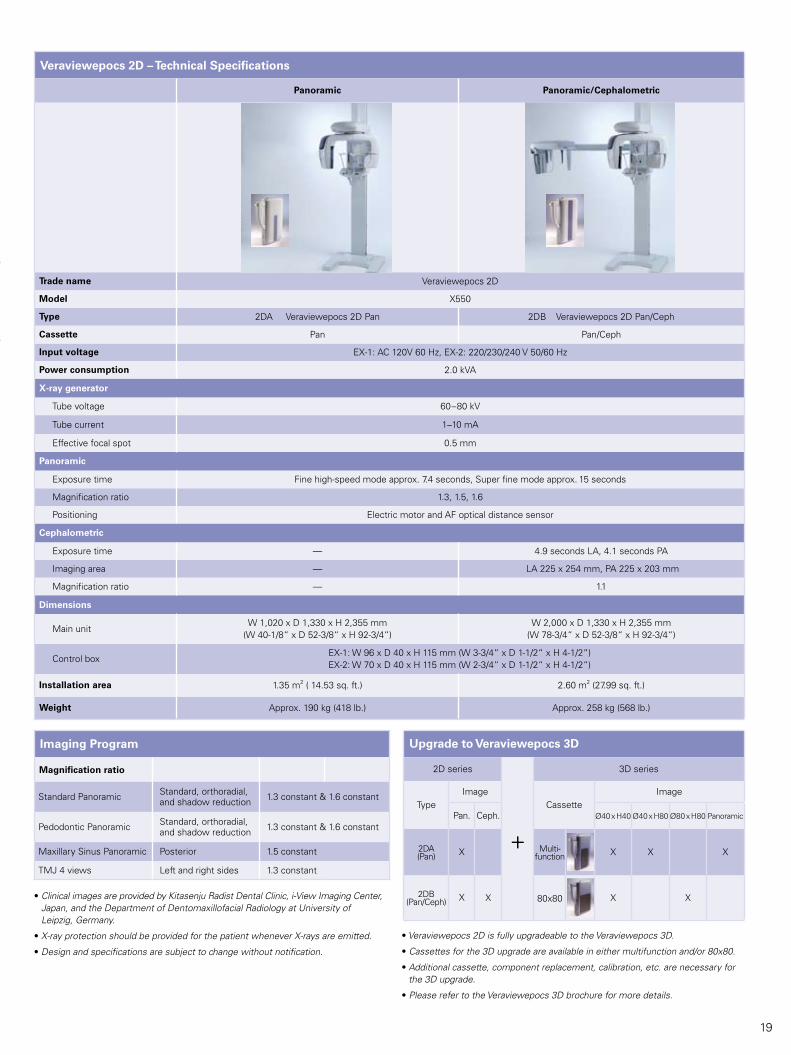
Veraviewepocs 2D – Technical Specifications
Panoramic Panoramic/Cephalometric
Trade name Veraviewepocs 2D
Model X550
Type 2DA Veraviewepocs 2D Pan 2DB Veraviewepocs 2D Pan/Ceph
Cassette Pan Pan/Ceph
Input voltage EX-1: AC 120V 60 Hz, EX-2: 220/230/240 V 50/60 Hz
Power consumption 2.0 kVA
X-ray generator
Tube voltage 60–80 kV
Tube current 1–10 mA
Effective focal spot 0.5 mm
Panoramic
Exposure time Fine high-speed mode approx. 7.4 seconds, Super fine mode approx. 15 seconds
Magnification ratio 1.3, 1.5, 1.6
Positioning Electric motor and AF optical distance sensor
Cephalometric
Exposure time — 4.9 seconds LA, 4.1 seconds PA
Imaging area — LA 225 x 254 mm, PA 225 x 203 mm
Magnification ratio — 1.1
Dimensions
Main unitW 1,020 x D 1,330 x H 2,355 mm
(W 40-1/8“ x D 52-3/8“ x H 92-3/4“)W 2,000 x D 1,330 x H 2,355 mm
(W 78-3/4“ x D 52-3/8“ x H 92-3/4“)
Control boxEX-1: W 96 x D 40 x H 115 mm (W 3-3/4“ x D 1-1/2“ x H 4-1/2“) EX-2: W 70 x D 40 x H 115 mm (W 2-3/4“ x D 1-1/2“ x H 4-1/2“)
Installation area 1.35 m2 ( 14.53 sq. ft.) 2.60 m2 (27.99 sq. ft.)
Weight Approx. 190 kg (418 lb.) Approx. 258 kg (568 lb.)
Imaging Program
Magnification ratio
Standard Panoramic Standard, orthoradial, and shadow reduction 1.3 constant & 1.6 constant
Pedodontic Panoramic Standard, orthoradial, and shadow reduction 1.3 constant & 1.6 constant
Maxillary Sinus Panoramic Posterior 1.5 constant
TMJ 4 views Left and right sides 1.3 constant
Upgrade to Veraviewepocs 3D
2D series
+
3D series
TypeImage
CassetteImage
Pan. Ceph. Ø40 x H40 Ø40 x H80 Ø80 x H80 Panoramic
2DA (Pan) X Multi-
function X X X
2DB (Pan/Ceph) X X 80x80 X X• Clinical images are provided by Kitasenju Radist Dental Clinic, i-View Imaging Center,
Japan, and the Department of Dentomaxillofacial Radiology at University of Leipzig, Germany.
• X-ray protection should be provided for the patient whenever X-rays are emitted.
• Design and specifications are subject to change without notification.
• Veraviewepocs 2D is fully upgradeable to the Veraviewepocs 3D.
• Cassettes for the 3D upgrade are available in either multifunction and/or 80x80.
• Additional cassette, component replacement, calibration, etc. are necessary for the 3D upgrade.
• Please refer to the Veraviewepocs 3D brochure for more details.
19

L-321 01/08L-337 04/08
Diagnostic/Imaging Equipment
Treatment Units
Instruments
Laser Equipment
Laboratory Devices
Educational and Training Systems
Auxiliaries
Thinking ahead. Focused on life.
In 1916, Junichi Morita started to import products of the leading dental equipment manufacturers into Japan, where demands for modern dentistry were growing. His venture some attempts of supplying selected products for oral healt h care has grown steadily by receiving valuable support and guidance from the dental pro fession. His enterprising spirit lives through the decades, and all Morita Group Companies join in continuing to pursue marketing, distribution and services, as well as R&D and manufacturing, in collaboration with world leaders in healthcare products and research organizations.
Distributed by
J. MORITA USA, INC. 9 Mason, lrvine, CA 92618 U.S.A. Toll Free: (800) 831-3222, Fax: (949) 465-1095, www.jmoritausa.com
J. MORITA EUROPE GMBH Justus-von-Liebig-Strasse 27A, D-63128 Dietzenbach, Germany Tel: +49-6074-836-0, Fax: +49-6074-836-299, www.jmoritaeurope.com
J. MORITA CORPORATION AUSTRALIA & NEW ZEALAND 247 Coward Street, Suite 2.05, Mascot NSW 2020, Australia Tel: +61 2 9667 3555, Fax: +61 2 9667 3577
J. MORITA MIDDLE EAST Saraya Al Wessam Bldg., Tower A, Appt. 902 Cross roads Tag Roasaa & Abu Heif, Saba Pacha, Alexandria, Egypt Tel: 203 58 222 94, Fax: 203 58 222 96, www.jmoritamiddleeast.com
J. MORITA CORPORATION 33-18, 3-Chome, Tarumi-cho Suita City, Osaka, 564-8650 Japan Tel: +81-6-6380-2525, Fax: +81-6-6380-0585 www.asia.morita.com, www.oceania.morita.com
Developed and Manufactured by
J. MORITA MFG. CORP. 680 Higashihama Minami-cho, Fushimi-ku, Kyoto, 612-8533 Japan Tel: +81-75-611-2141, Fax: +81-75-622-4595, www.jmorita-mfg.com


![Morita theory for group corings - Semantic Scholar · The first Morita context was constructed by Chase and Sweedler [9], which was generalized by Doi [12]. Morita contexts similar](https://static.fdocuments.in/doc/165x107/6055620657f9b55ddf7d34b2/morita-theory-for-group-corings-semantic-scholar-the-irst-morita-context-was.jpg)