Verasys™ BACnet® MS/TP Communications...The BACnet® protocol Master-Slave/Tok en-Passing (MS/TP)...
24
Refer to the QuickLIT website for the most up-to-date version of this document. Verasys™ BACnet® MS/TP Communications Technical Bulletin 1 TM Introduction . . . . . . . . . . . . . . . . . . . . . . . . . . . . . . . . . . . . . . . . . . . . . . . . . . . . . . . . . . . . . . . . 3 Overview . . . . . . . . . . . . . . . . . . . . . . . . . . . . . . . . . . . . . . . . . . . . . . . . . . . . . . . . . . . . . . . . . . 3 MS/TP Bus Types . . . . . . . . . . . . . . . . . . . . . . . . . . . . . . . . . . . . . . . . . . . . . . . . . . . . . . . . . . . . . . . 4 System Bus (FC Bus) . . . . . . . . . . . . . . . . . . . . . . . . . . . . . . . . . . . . . . . . . . . . . . . . . . . . . . . . . . . . 4 Zone Bus (CS Bus) . . . . . . . . . . . . . . . . . . . . . . . . . . . . . . . . . . . . . . . . . . . . . . . . . . . . . . . . . . . . . . 4 Sensor Bus (SA Bus) . . . . . . . . . . . . . . . . . . . . . . . . . . . . . . . . . . . . . . . . . . . . . . . . . . . . . . . . . . . . . 5 Baud Rates on an MS/TP Bus . . . . . . . . . . . . . . . . . . . . . . . . . . . . . . . . . . . . . . . . . . . . . . . . . . . . . 5 EOL Terminations on an MS/TP Bus . . . . . . . . . . . . . . . . . . . . . . . . . . . . . . . . . . . . . . . . . . . . . . . 5 EOL Terminator Module. . . . . . . . . . . . . . . . . . . . . . . . . . . . . . . . . . . . . . . . . . . . . . . . . . . . . . . . . . . 5 MS/TP Bus Rules, Specifications, and Terminations . . . . . . . . . . . . . . . . . . . . . . . . . . . . . . 7 System Bus (FC Bus) Rules and Specifications . . . . . . . . . . . . . . . . . . . . . . . . . . . . . . . . . . . . . . 7 Zone Bus Rules and Specifications . . . . . . . . . . . . . . . . . . . . . . . . . . . . . . . . . . . . . . . . . . . . . . . . 9 Sensor Bus Rules and Specifications . . . . . . . . . . . . . . . . . . . . . . . . . . . . . . . . . . . . . . . . . . . . . 10 MS/TP Bus Cable Recommendations . . . . . . . . . . . . . . . . . . . . . . . . . . . . . . . . . . . . . . . . . . 11 Screw Terminal Blocks for Connecting the Bus Cable . . . . . . . . . . . . . . . . . . . . . . . . . . . . . . . 12 Grounding the Bus Cable Shield . . . . . . . . . . . . . . . . . . . . . . . . . . . . . . . . . . . . . . . . . . . . . . . . . 13 RJ-Style Modular Jack and Cables for Sensor Bus . . . . . . . . . . . . . . . . . . . . . . . . . . . . . . . . . . 15 Device Addresses on the System, Zone and Sensor Bus . . . . . . . . . . . . . . . . . . . . . . . . . . 16 Setting a Device Address . . . . . . . . . . . . . . . . . . . . . . . . . . . . . . . . . . . . . . . . . . . . . . . . . . . . . . . 16 Troubleshooting . . . . . . . . . . . . . . . . . . . . . . . . . . . . . . . . . . . . . . . . . . . . . . . . . . . . . . . . . . . 18 Wiring . . . . . . . . . . . . . . . . . . . . . . . . . . . . . . . . . . . . . . . . . . . . . . . . . . . . . . . . . . . . . . . . . . . . . . . 18 Addressing . . . . . . . . . . . . . . . . . . . . . . . . . . . . . . . . . . . . . . . . . . . . . . . . . . . . . . . . . . . . . . . . . . . 18 Correcting Physical Problems with a Communications Bus. . . . . . . . . . . . . . . . . . . . . . . . . . . 18 Appendix: System Bus (FC Bus) Auxiliary Devices . . . . . . . . . . . . . . . . . . . . . . . . . . . . . . 20 Repeaters . . . . . . . . . . . . . . . . . . . . . . . . . . . . . . . . . . . . . . . . . . . . . . . . . . . . . . . . . . . . . . . . . . . . 20 Verasys™ BACnet® MS/TP Communications Technical Bulletin Code No. LIT-12012362 Issued October 2017
Transcript of Verasys™ BACnet® MS/TP Communications...The BACnet® protocol Master-Slave/Tok en-Passing (MS/TP)...
Refer to the QuickLIT website for the most up-to-date version of this document.
Verasys™ BACnet® MS/TP CommunicationsTechnical Bulletin
Code No. LIT-12012362Issued October 2017
Introduction . . . . . . . . . . . . . . . . . . . . . . . . . . . . . . . . . . . . . . . . . . . . . . . . . . . . . . . . . . . . . . . .3
Overview . . . . . . . . . . . . . . . . . . . . . . . . . . . . . . . . . . . . . . . . . . . . . . . . . . . . . . . . . . . . . . . . . .3
MS/TP Bus Types. . . . . . . . . . . . . . . . . . . . . . . . . . . . . . . . . . . . . . . . . . . . . . . . . . . . . . . . . . . . . . . 4
System Bus (FC Bus) . . . . . . . . . . . . . . . . . . . . . . . . . . . . . . . . . . . . . . . . . . . . . . . . . . . . . . . . . . . . 4
Zone Bus (CS Bus) . . . . . . . . . . . . . . . . . . . . . . . . . . . . . . . . . . . . . . . . . . . . . . . . . . . . . . . . . . . . . . 4
Sensor Bus (SA Bus) . . . . . . . . . . . . . . . . . . . . . . . . . . . . . . . . . . . . . . . . . . . . . . . . . . . . . . . . . . . . . 5
Baud Rates on an MS/TP Bus. . . . . . . . . . . . . . . . . . . . . . . . . . . . . . . . . . . . . . . . . . . . . . . . . . . . . 5
EOL Terminations on an MS/TP Bus . . . . . . . . . . . . . . . . . . . . . . . . . . . . . . . . . . . . . . . . . . . . . . . 5
EOL Terminator Module. . . . . . . . . . . . . . . . . . . . . . . . . . . . . . . . . . . . . . . . . . . . . . . . . . . . . . . . . . . 5
MS/TP Bus Rules, Specifications, and Terminations . . . . . . . . . . . . . . . . . . . . . . . . . . . . . .7
System Bus (FC Bus) Rules and Specifications. . . . . . . . . . . . . . . . . . . . . . . . . . . . . . . . . . . . . . 7
Zone Bus Rules and Specifications . . . . . . . . . . . . . . . . . . . . . . . . . . . . . . . . . . . . . . . . . . . . . . . . 9
Sensor Bus Rules and Specifications . . . . . . . . . . . . . . . . . . . . . . . . . . . . . . . . . . . . . . . . . . . . . 10
MS/TP Bus Cable Recommendations . . . . . . . . . . . . . . . . . . . . . . . . . . . . . . . . . . . . . . . . . .11
Screw Terminal Blocks for Connecting the Bus Cable . . . . . . . . . . . . . . . . . . . . . . . . . . . . . . . 12
Grounding the Bus Cable Shield . . . . . . . . . . . . . . . . . . . . . . . . . . . . . . . . . . . . . . . . . . . . . . . . . 13
RJ-Style Modular Jack and Cables for Sensor Bus . . . . . . . . . . . . . . . . . . . . . . . . . . . . . . . . . . 15
Device Addresses on the System, Zone and Sensor Bus. . . . . . . . . . . . . . . . . . . . . . . . . .16
Setting a Device Address . . . . . . . . . . . . . . . . . . . . . . . . . . . . . . . . . . . . . . . . . . . . . . . . . . . . . . . 16
Troubleshooting . . . . . . . . . . . . . . . . . . . . . . . . . . . . . . . . . . . . . . . . . . . . . . . . . . . . . . . . . . .18
Wiring . . . . . . . . . . . . . . . . . . . . . . . . . . . . . . . . . . . . . . . . . . . . . . . . . . . . . . . . . . . . . . . . . . . . . . . 18
Addressing . . . . . . . . . . . . . . . . . . . . . . . . . . . . . . . . . . . . . . . . . . . . . . . . . . . . . . . . . . . . . . . . . . . 18
Correcting Physical Problems with a Communications Bus. . . . . . . . . . . . . . . . . . . . . . . . . . . 18
Appendix: System Bus (FC Bus) Auxiliary Devices . . . . . . . . . . . . . . . . . . . . . . . . . . . . . .20
Repeaters . . . . . . . . . . . . . . . . . . . . . . . . . . . . . . . . . . . . . . . . . . . . . . . . . . . . . . . . . . . . . . . . . . . . 20
Verasys™ BACnet® MS/TP Communications Technical Bulletin
1
TM

Configuring Repeaters . . . . . . . . . . . . . . . . . . . . . . . . . . . . . . . . . . . . . . . . . . . . . . . . . . . . . . . . . . . 20
Surge Protectors . . . . . . . . . . . . . . . . . . . . . . . . . . . . . . . . . . . . . . . . . . . . . . . . . . . . . . . . . . . . . . 21
Verasys™ BACnet® MS/TP Communications Technical Bulletin
2

Verasys™ BACnet® MS/TP CommunicationsTechnical Bulletin
IntroductionThe BACnet® protocol Master-Slave/Token-Passing (MS/TP) communications bus is a local network that connects supervisory controllers and field controllers to field point interfaces.
This document describes the specifications, device limits, and rules of the MS/TP communications bus, as well as how to wire and terminate devices, and troubleshoot device communication on the MS/TP bus.
This document provides information about the rules, requirements, limits, specifications, and configuration of the MS/TP bus. This information helps you design, wire, or troubleshoot an MS/TP bus application.
OverviewBACnet® standard protocol SSPC-135, Clause 9 provides the foundation for the MS/TP bus. The BACnet MS/TP protocol is a peer-to-peer, multiple-master protocol that is based on token passing. Only master devices receive the token, and only the device holding the token is allowed to originate a message on the bus.
The token passes from master device to master device by means of a small message. The token passes in consecutive order, starting with the lowest address. Slave devices communicate only when responding to a data request from a master device.
The Verasys System uses an MS/TP bus (Figure 1) for three types of buses.
The bus supervisor communicates with devices on the supervised bus and with devices on the next (higher level) bus on the network. The bus supervisor typically starts the communication on the System Bus (FC Bus), Zone Bus (CS Bus) or Sensor Bus (SA Bus).
Table 1: BACnet MS/TP Bus Types and Bus SupervisorsBus Type Bus Supervisor
System Bus (Field Controller [FC] Bus) Smart Building Hub (SBH)
Zone Bus (CS Bus) Zone Coordinator
Sensor Bus (SA Bus) Field Controller
Verasys™ BACnet® MS/TP Communications Technical Bulletin
1

MS/TP Bus Types
System Bus (FC Bus)
The System Bus (FC Bus) connects a Verasys System Smart Building Hub with Smart equipment units, TEC3000 thermostats, zone coordinators and other Verasys system-compatible devices. You cannot connect third-party BACnet MS/TP devices on the System Bus because the Smart Building Hub does not support third-party BACnet MS/TP devices.
On a System Bus (FC Bus), the Smart Building Hub is the bus supervisor. A System Bus supports up to three bus segments. See System Bus (FC Bus) Rules and Specifications for more information.
Zone Bus (CS Bus)
The Zone Bus (CS Bus) is specific to the Verasys Zone Coordinator. The zone coordinator has both a System Bus (FC Bus) connection and a Zone Bus (CS Bus) connection.
Figure 1: MS/TP Communications Bus Example
IP Backbone
Smart Building Hub
(Wifi Connectivity)
System Bus (FC Bus)
Up to 100
Devices
TEC36xx IOM100Simplicity Smart
Equipment
Single Zone Unit
Verasys Zone
Coordinator
Simplicity Smart
Equipment VAV
or COBP Unit
Verasys Equipment Controller
(VEC) VAV or COBP Controller
Up to 32 Zones
Zo
ne
Bu
s(C
SB
us)
Up to 32 Zones
Zo
ne
Bu
s(C
SB
us)
Sensor Bus
Sensor Bus
Sensor Bus
Sensor Bus
Sensor Bus
Sensor Bus
Verasys™ BACnet® MS/TP Communications Technical Bulletin
2

The Zone Bus (CS Bus) port is called the Connected Service port on the board and supports only ZEC300, ZEC310, ZEC400, ZEC410, BYP200, VEC100, and Simplicity® SMART Equipment controllers. The Zone Bus (CS Bus) connects the devices to make a complete change-over-bypass or variable air volume system, then communicates this system to the Smart Building Hub using the System Bus (FC Bus).
Sensor Bus (SA Bus)
The Sensor Bus connects ZECs with network sensors. On a Sensor Bus, the ZEC is the bus supervisor. The Sensor Bus is a separate MS/TP bus that only supports defined devices. The bus does not support bus segments. See Sensor Bus (SA Bus) Rules and Specifications for more information.
Baud Rates on an MS/TP BusYou can configure an MS/TP bus at one of four different baud rates. All of the devices on the MS/TP bus must communicate at the same baud rate.
The baud rate setting determines the rate at which devices communicate data over the bus. The Verasys MS/TP bus baud rate is 38.4 kbps. All devices default to this or to the Auto setting. In the Auto setting, the devices automatically configure to the network. The devices listen for communication from the bus supervisor then automatically set their baud rate to the bus supervisor’s baud rate.
EOL Terminations on an MS/TP BusDaisy-chained RS485-protocol networks typically require some type of end-of-line (EOL) termination to reduce interference caused by signal reflection that occurs when data transmissions reach the end of a bus segment and bounce back on the segment. The high baud rates on MS/TP bus applications require robust EOL termination and strict adherence to the EOL termination rules. Figure 2 shows an example of the EOL termination settings on an MS/TP bus application.
The EOL termination requirements for the System Bus (FC Bus) are different from the Zone Bus and the Sensor Bus requirements.
The System Bus (FC Bus) requires EOL termination at the end of each bus segment. Set the EOL termination switch on a repeater’s device connection to ON only when the repeater connection terminates a bus segment.
The Zone Bus (CS Bus) requires EOL termination at the end of each bus segment.
On a Sensor Bus, you must enable EOL termination on at least one device. Because EOL termination is always enabled on the Sensor Bus supervisor, this requirement is always met; however, for enhanced bus performance, we recommend that you enable EOL termination on the devices at each end of the Sensor Bus.
EOL Terminator Module
The MS-BACEOL-0 RS485 EOL Terminator provides EOL termination on System Bus (FC Bus) segments when the device connected at the end of a bus segment does not have integral EOL termination capability.
The EOL terminator is a compact, lightweight, module wrapped in a protective cover. The EOL connects directly to the terminating device on a bus segment with the attached wire leads. The EOL requires 24 VAC, Class 2 power supplied by the field device or another 24 VAC source.
An EOL terminator is required in all Verasys applications wherever a terminating device on a System Bus (FC Bus) segment does not have integral EOL termination (for example, PEAK® 18 Controllers or VEC100 controller).
Verasys™ BACnet® MS/TP Communications Technical Bulletin
3

Figure 2: EOL Terminations on an MS/TP Bus
IP Backbone
Smart Building Hub
(Wifi Connectivity)
System Bus (FC Bus)
TEC36xx IOM100Simplicity Smart
Equipment
Single Zone Unit
Verasys Zone
Coordinator
Simplicity Smart
Equipment VAV
or COBP Unit
Verasys Equipment Controller
(VEC) VAV or COBP Controller
Zo
ne
Bu
s(C
SB
us) Z
on
eB
us
(CS
Bu
s)
EOL
EOL
EOL
EOL
EOL
EOL
EOL Device EOL Switch turned on or MS-BACEOL-0 wired in
Note the Smart Building Hub does not have an EOL switch. To terminate a device that does not have an EOL
use an MS-BACEOL-0 and wire it to the end of the trunk or reposition the device to where it is not end of line.
Note the Verasys Zone coordinators have multiple end of line switches in this example the zone bus or CS
bus should be switch on. The system bus however should be off.
Sensor Bus
Sensor Bus
Sensor Bus
Sensor Bus
Sensor Bus
Sensor Bus
Verasys™ BACnet® MS/TP Communications Technical Bulletin
4

MS/TP Bus Rules, Specifications, and Terminations
System Bus (FC Bus) Rules and SpecificationsTable 4, Table 5, and Figure 3 provide rules and specifications for the System Bus (FC Bus).
Table 2: System Bus (FC Bus) RulesCategory Rules/Limits
General The Smart Building Hub only supports one FC Bus with a maximum of 100 supported devices, including a maximum of 10 zone coordinators (VSC100). Supported devices for the Verasys system include Simplicity Smart Equipment units, TEC36xx Thermostats, the IOM100 Controller, Verasys Zone Coordinators (VZC100), and PEAK® OEM controllers.
Number of Devices and Bus Segments
You can divide the System Bus (FC Bus) into bus segments. The System Bus (FC Bus) supports up to three segments. Each segment supports up to 50 devices per bus segment (maximum, not to exceed 100 devices per System Bus).Note: Bus segments on the System Bus (FC Bus) are connected with repeaters (only). You
may apply up to two cascaded repeaters to a System Bus (FC Bus) (to connect three bus segments).
Cable Length for System Bus and Zone Bus Segments
When all of the devices connected on the System Bus (FC Bus), the cable length limits (using 22 AWG 3-wire twisted, shielded cable) are as follows:• Each bus segment - up to 1,520 m (5,000 ft)• Each System Bus - up to 4,750 m (15,000 ft)
Recommended Cable1
1. The recommended cable type provides the best bus performance. See MS/TP Bus Cable Recommendations for information on alternative cable types and lengths that may be used in MS/TP applications.
22 AWG Stranded, 3-Wire Twisted, Shielded Cable
EOL Termination You must set the EOL switch to On (or install an EOL terminator) on the two devices located at either end of each bus segment. You must set the EOL switches to Off (or disable EOL termination) for all other devices on the bus segment. See EOL Terminations on an MS/TP Bus for more information.
Figure 3: System Bus (FC Bus) with Three Bus Segments Connected with Repeaters
EOL SwitchON
TR R
Bus Segment1,520 m (5,000 ft) Maximum
50 Device ConnectionsVerasys
= EOL Termination switch ONT
R = Repeater
T T TT T
Note: For optimum noise protection the locations with G are the ideal shield.
Bus Segment1,520 m (5,000 ft) Maximum
50 Device ConnectionsVerasys
(Maximum)4,570 m (15,000 ft) Maximum
100 Total Verasys Device Connections
System Bus (FC Bus)Verasys SmartBuilding Hub
Bus Segment1,520 m (5,000 ft) Maximum
50 Device ConnectionsVerasys
FIG:FC_SEGS
Verasys™ BACnet® MS/TP Communications Technical Bulletin
5

Notes:
• For optimal noise protection, the locations with G are the ideal shield grounding locations. This provides one shield ground per bus segment, grounding at the source of the bus for that segment. You may ground the shield only at the SBH if the shields are made continuous across repeaters side A and B; however, the noise protection is reduced in this configuration.
• While each bus segment supports up to 50 devices, the total device count on the System Bus (FC Bus) cannot exceed 100, including the SBH.
The bus segments on an System Bus (FC Bus) are connected only using repeaters. A repeater has two device connections, which are independent of each other. Each device connection on the repeater is connected to a bus segment, the same as any other device connection on the segment. You can connect a repeater device at the end of a bus segment or anywhere along the segment. When connecting a repeater device at the end of a bus segment, you must enable EOL termination on that repeater device connection. For more examples of repeaters on System Buses (FC Buses), see Figure 2 and Appendix: System Bus (FC Bus) Auxiliary Devices.
Table 3: System Bus (FC Bus) SpecificationsCategory Specification
Error Checking Message headers checked using an 8-bit Cyclic Redundancy Check (CRC) test.Message data checked using a 16-bit CRC test.
Device Addressing 0–255 (See Setting a Device Address for more information.)
Data Transmission Standard
RS485
Signaling Method BACnet® MS/TP
Signaling Rate 38,400 baud
Transient Immunity Meets EN61000-4-4 and EN6100-4-5 requirements for heavy industrial applications.Protected against misapplication of 24 VAC.
EOL Termination Method Integral EOL Termination switch or add-on EOL Terminator module. See EOL Terminations on an MS/TP Bus. Do not use third-party EOL termination.
Shield Grounding Only one hard ground connection per bus segment when using shielded cable.(See Grounding the Bus Cable Shield.)
Physical Configuration Daisy-chained
Optional Vendor Components
Repeaters:• Acromag 4683-TTM-1F (115 VAC)• Acromag 4683-TTM-2F (230 VAC)• Acromag 4683-TTM-3F (24 VAC)Note: A repeater is required to support more than 50 devices per trunk segment or trunk
cable segment longer than 1,524 m (5,000 ft). Only the listed Acromag 4683 series repeaters provide EOL termination switching that is compatible with Metasys® MS/TP.
Transient Eliminator:Advanced Protection Technologies Transient Eliminator TE/JC04C12
Verasys™ BACnet® MS/TP Communications Technical Bulletin
6
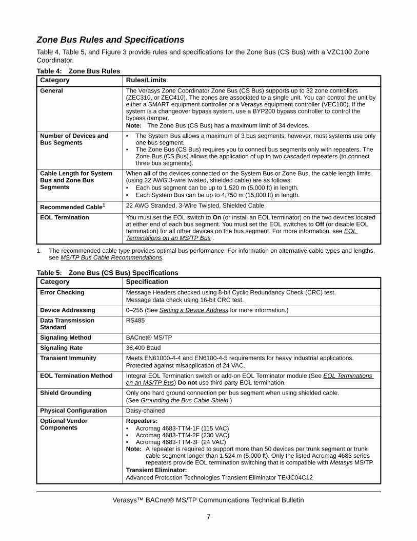
Zone Bus Rules and SpecificationsTable 4, Table 5, and Figure 3 provide rules and specifications for the Zone Bus (CS Bus) with a VZC100 Zone Coordinator.
Table 4: Zone Bus RulesCategory Rules/Limits
General The Verasys Zone Coordinator Zone Bus (CS Bus) supports up to 32 zone controllers (ZEC310, or ZEC410). The zones are associated to a single unit. You can control the unit by either a SMART equipment controller or a Verasys equipment controller (VEC100). If the system is a changeover bypass system, use a BYP200 bypass controller to control the bypass damper.Note: The Zone Bus (CS Bus) has a maximum limit of 34 devices.
Number of Devices and Bus Segments
• The System Bus allows a maximum of 3 bus segments; however, most systems use only one bus segment.
• The Zone Bus (CS Bus) requires you to connect bus segments only with repeaters. The Zone Bus (CS Bus) allows the application of up to two cascaded repeaters (to connect three bus segments).
Cable Length for System Bus and Zone Bus Segments
When all of the devices connected on the System Bus or Zone Bus, the cable length limits (using 22 AWG 3-wire twisted, shielded cable) are as follows:• Each bus segment can be up to 1,520 m (5,000 ft) in length.• Each System Bus can be up to 4,750 m (15,000 ft) in length.
Recommended Cable1
1. The recommended cable type provides optimal bus performance. For information on alternative cable types and lengths, see MS/TP Bus Cable Recommendations.
22 AWG Stranded, 3-Wire Twisted, Shielded Cable
EOL Termination You must set the EOL switch to On (or install an EOL terminator) on the two devices located at either end of each bus segment. You must set the EOL switches to Off (or disable EOL termination) for all other devices on the bus segment. For more information, see EOL Terminations on an MS/TP Bus .
Table 5: Zone Bus (CS Bus) SpecificationsCategory Specification
Error Checking Message Headers checked using 8-bit Cyclic Redundancy Check (CRC) test.Message data check using 16-bit CRC test.
Device Addressing 0–255 (See Setting a Device Address for more information.)
Data Transmission Standard
RS485
Signaling Method BACnet® MS/TP
Signaling Rate 38,400 Baud
Transient Immunity Meets EN61000-4-4 and EN6100-4-5 requirements for heavy industrial applications.Protected against misapplication of 24 VAC.
EOL Termination Method Integral EOL Termination switch or add-on EOL Terminator module (See EOL Terminations on an MS/TP Bus) Do not use third-party EOL termination.
Shield Grounding Only one hard ground connection per bus segment when using shielded cable.(See Grounding the Bus Cable Shield.)
Physical Configuration Daisy-chained
Optional Vendor Components
Repeaters:• Acromag 4683-TTM-1F (115 VAC)• Acromag 4683-TTM-2F (230 VAC)• Acromag 4683-TTM-3F (24 VAC)Note: A repeater is required to support more than 50 devices per trunk segment or trunk
cable segment longer than 1,524 m (5,000 ft). Only the listed Acromag 4683 series repeaters provide EOL termination switching that is compatible with Metasys MS/TP.
Transient Eliminator:Advanced Protection Technologies Transient Eliminator TE/JC04C12
Verasys™ BACnet® MS/TP Communications Technical Bulletin
7

Sensor Bus (SA Bus) Rules and SpecificationsThe Sensor Bus connects NS-Series network sensors to field controllers. Table 6 and Table 7 provide SA Bus rules and specifications.
Table 6: Sensor Bus RulesCategory Rules/Limits
General Each bus supervisor supports one SA Bus (and each SA Bus is a single segment).
Number of Devices Supported on the Bus
• A Sensor Bus supports up to 10 devices. However a Verasys system has only one or two devices. The Sensor Bus supervisor provides power for all slave devices connected to the Sensor Bus for network sensors. A CO2 Sensor requires additional 24 VAC power.
• Sensor Buses do not support repeaters.
Cable Length • 365 m (1,200 ft) maximum• 152 m (500 ft) maximum distance between an NS network sensor and the bus supervisor
using bus cable connected to the SA Bus screw terminal blocks• 30 m (100 ft) maximum length for network sensors using bus cables connected to the
RJ-Style modular jack (6-Pin SA Bus Port)• 366 m (1,200 ft) maximum
Recommended Cable Type1
1. The recommended cable types provide optimal bus performance. See MS/TP Bus Cable Recommendations for information on alternative cable types.
Screw Terminal Connections: 22 AWG Stranded 4-wire, 2-Twisted Pairs, Shielded Cable for screw terminals.Modular Jack Connections: 6-Pin RJ-Style Modular Connectors with 24 or 26 AWG Solid 6-Wire, 3 Twisted-Pairs
EOL Termination Each Sensor Bus supervisor has integral (fixed ON) EOL termination, which typically provides sufficient EOL termination on an Sensor Bus. Long Sensor Bus runs, or persistent communication problems on a Sensor Bus may require EOL termination at the last device on the Sensor Bus (in addition to the integral EOL termination at the Sensor Bus supervisor).
Mixing Device Types Do not mix RJ-style modular (phone) jack devices and screw terminal devices on the Sensor Bus.
Table 7: Sensor Bus SpecificationsCategory Specification
Error Checking • Message Headers checked using 8-bit CRC test.• Message data check using 16-bit CRC test
Device Addressing 0–255 (See Device Addresses on the System, Zone and Sensor Bus for more information.)
Data Transmission Standard RS485
Signaling Method BACnet® MS/TP
Signaling Rate 9600; 19,200; 38,400 (default); or 76,800 baud as selected by the bus supervisor
Transient Immunity Meets EN61000-4-4 and EN6100-4-5 requirements for heavy industrial applications Protected against misapplication of 24 VAC
Shield Grounding One hard ground per bus segment when using shielded cable
Physical Configuration Daisy-chained (screw terminal only)
Verasys™ BACnet® MS/TP Communications Technical Bulletin
8

MS/TP Bus Cable RecommendationsFor the best performance on System Bus and Zone Bus applications, use 22 AWG stranded wire in a shielded cable with proper cable shield grounding. This recommendation applies to both local and remote field bus installations. Other wire gauges and non-shielded cable may provide acceptable bus performance in many applications, especially applications that have short cable runs and low ambient inductive noise levels.
Table 8 provides cable recommendations for MS/TP applications. The recommended System Bus, Zone Bus, and Sensor Bus cables are available from Belden CDT Inc. and Anixter, Inc.
Note: In Table 8, the shielded bus and cable types are recommended; the non-shielded bus and cable types are acceptable.
Table 8: Cable for System, Zone and SA Buses in Order of PreferenceBus and Cable Type Non-Plenum Applications Plenum Applications
Part Number O.D. Part Number O.D.
System and Zone Bus: 22 AWG Stranded, 3-Wire Twisted Shielded Cable1
1. We strongly recommend 3-wire (System Bus and Zone Bus) and 4-wire, 2 twisted-pair (SA Bus), 22 AWG stranded, shielded cable. A 22 gauge cable offers the best performance for various baud rates, cable distances, and number of trunk devices primarily due to lower conductor-to-conductor capacitance. Shielded cable offers better overall electrical noise immunity than non-shielded cable. Observe the shield grounding requirements.
Anixter: CBL-22/3-FC-PVCBelden®: B5501FE
0.138 in. Anixter: CBL-22/3-FC-PLNBelden: B6501FE
0.140 in.
Sensor Bus (Terminal Block): 22 AWG Stranded, 4-Wire, 2 Twisted-Pair Shielded Cable1
Anixter: CBL-22/2P-SA-PVCBelden: B5541FE
0.209 in. Anixter: CBL-22/2P-SA-PLNBelden: B6541FE
0.206 in.
Sensor Bus (Modular Jack): 26 AWG Solid 6-Wire, 3 Twisted-Pair Cable2
2. We recommend 26 AWG solid, 6-wire (3 twisted pairs) cable as the best fit for fabricating modular cables with the modular jack housing assembly. Ensure the cable you use fits the modular jack housing. The preassembled cables available from Anixter (Part No. CBL-NETWORKxxx) use 24 gauge wire.
— — Anixter preassembled: CBL-NETWORK25CBL-NETWORK50CBL-NETWORK75CBL-NETWORK100
0.15 in.
System and Zone Bus: 22 AWG Stranded, 3-Wire Twisted Non-Shielded Cable
Belden: B5501UE 0.135 in. Belden: B6501UE 0.131 in.
Sensor Bus (Terminal Block): 22 AWG Stranded, 4-Wire, 2 Twisted-Pair Non-Shielded Cable
Belden: B5541UE 0.206 in. Belden: B6541UE 0.199 in.
Verasys™ BACnet® MS/TP Communications Technical Bulletin
9
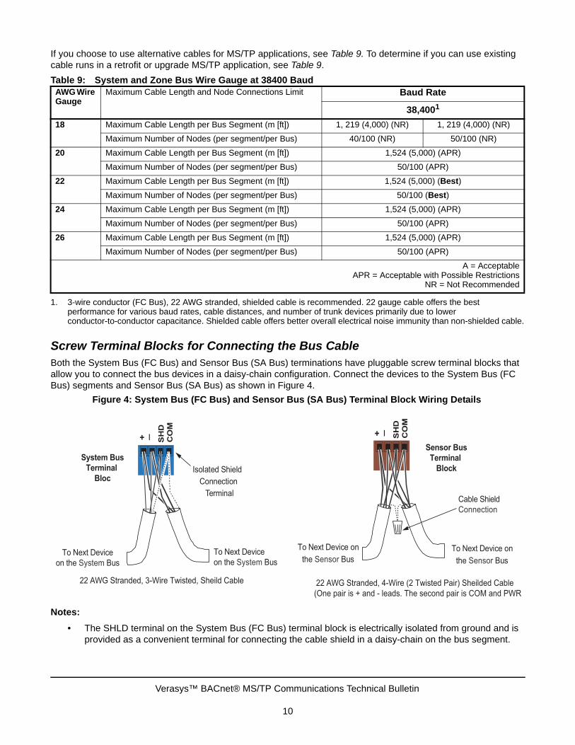
If you choose to use alternative cables for MS/TP applications, see Table 9. To determine if you can use existing cable runs in a retrofit or upgrade MS/TP application, see Table 9.
Screw Terminal Blocks for Connecting the Bus CableBoth the System Bus (FC Bus) and Sensor Bus (SA Bus) terminations have pluggable screw terminal blocks that allow you to connect the bus devices in a daisy-chain configuration. Connect the devices to the System Bus (FC Bus) segments and Sensor Bus (SA Bus) as shown in Figure 4.
Notes:
• The SHLD terminal on the System Bus (FC Bus) terminal block is electrically isolated from ground and is provided as a convenient terminal for connecting the cable shield in a daisy-chain on the bus segment.
Table 9: System and Zone Bus Wire Gauge at 38400 BaudAWG Wire Gauge
Maximum Cable Length and Node Connections Limit Baud Rate
38,4001
1. 3-wire conductor (FC Bus), 22 AWG stranded, shielded cable is recommended. 22 gauge cable offers the best performance for various baud rates, cable distances, and number of trunk devices primarily due to lower conductor-to-conductor capacitance. Shielded cable offers better overall electrical noise immunity than non-shielded cable.
18 Maximum Cable Length per Bus Segment (m [ft]) 1, 219 (4,000) (NR) 1, 219 (4,000) (NR)
Maximum Number of Nodes (per segment/per Bus) 40/100 (NR) 50/100 (NR)
20 Maximum Cable Length per Bus Segment (m [ft]) 1,524 (5,000) (APR)
Maximum Number of Nodes (per segment/per Bus) 50/100 (APR)
22 Maximum Cable Length per Bus Segment (m [ft]) 1,524 (5,000) (Best)
Maximum Number of Nodes (per segment/per Bus) 50/100 (Best)
24 Maximum Cable Length per Bus Segment (m [ft]) 1,524 (5,000) (APR)
Maximum Number of Nodes (per segment/per Bus) 50/100 (APR)
26 Maximum Cable Length per Bus Segment (m [ft]) 1,524 (5,000) (APR)
Maximum Number of Nodes (per segment/per Bus) 50/100 (APR)
A = AcceptableAPR = Acceptable with Possible Restrictions
NR = Not Recommended
Figure 4: System Bus (FC Bus) and Sensor Bus (SA Bus) Terminal Block Wiring Details
22 AWG Stranded, 4-Wire (2 Twisted Pair) Sheilded Cable
(One pair is + and - leads. The second pair is COM and PWR
+ _ CO
MS
HD + _ CO
MS
HD
To Next Device
on the System Bus
Isolated Shield
Connection
Terminal
Sensor BusTerminal
BlockSystem Bus
Terminal Bloc
To Next Device on
the Sensor Bus
To Next Device on
the Sensor Bus
Cable Shield
Connection
To Next Device
on the System Bus
22 AWG Stranded, 3-Wire Twisted, Sheild Cable
Verasys™ BACnet® MS/TP Communications Technical Bulletin
10

• Do not mix RJ-style modular (phone) jack and screw terminal devices on the Sensor Bus. Due to the permanent internal Sensor Bus EOL termination contained in the ZEC controllers, using both the phone jack and terminal block effectively puts the EOL termination in the middle of the Sensor trunk, creating a star network configuration. This configuration violates the RS-485 network wiring guidelines and can cause unpredictable communication problems.
Grounding the Bus Cable ShieldInductive interference and Radio Frequency (RF) interference adversely affects MS/TP applications, causing poor bus performance and frequent device offline occurrences. Installing a properly grounded shielded bus cable in MS/TP applications greatly reduces the impact of ambient inductive noise and RF interference. Applications installed without shielded cable are much less tolerant to ambient interference.
We recommend installing MS/TP bus applications using shielded cable. In applications using shielded cable, it is very important to ground the cable shield properly. Improper shield grounding results in poor bus performance and frequent device offline occurrences.
To properly ground the cable shield on an MS/TP application, you must connect the cable shields on each bus segment in a daisy-chain (as shown in Figure 4). Each daisy-chained segment connect to a hard ground connection at only one point. Connect the cable shield to a hard ground close to the bus supervisor’s bus terminations. In metal panel or enclosure applications, connect the cable shield to ground where the bus cable enters the panel or enclosure that contains the bus supervisor. On bus segments without a bus supervisor, the best practice is to connect the cable shield to hard ground at a bus device near the middle of the bus segment.
In certain environments with high ambient inductive interference or strong radio frequency transmissions, MS/TP applications may require soft ground connections along the bus segments to enhance bus performance and reduce device offline occurrences, or possible device damage.
Examples of potential inductive interference include large motors, electrical contacts and relays, welding equipment, high-voltage conductors that are not in metal conduit or raceways, other high wattage devices within 10 m (30 ft) of the bus cable, and areas of frequent lightning.
Examples of potential radio frequency interference include locations near airports, hospitals, radio or television transmission towers, police and fire stations, or factories. Mobile transmitters in police, fire, emergency, and fleet vehicles are also potential sources of radio frequency interference.
Notes:
• The majority of properly grounded MS/TP applications do not require soft ground connections, but you should assess the potential interference that your application may encounter (before you install the bus). Prepare for soft ground connections when you make the bus terminations at the initial installation.
• Make soft ground connections within 2 inches of the bus terminations of any bus device that experiences frequent offline occurrences resulting from high ambient inductive or RF interference (Figure 5).
IMPORTANT: Ensure that the cable shield is connected to hard ground at only one point on the bus segment and is completely isolated from hard ground at all other points. Multiple hard ground connections on a bus segment can create ground loop currents in the cable shield, resulting in poor bus performance and frequent device offline occurrences.
Verasys™ BACnet® MS/TP Communications Technical Bulletin
11

Figure 5: Applying a Soft Ground Connection to a System Bus
System BusTerminal
Block
To Next Device on
the System Bus+ _ CO
MSH
D560 pF
Capacitor
To Next Device on
the System Bus
Cable Shield
connections
to Soft Ground
Verasys™ BACnet® MS/TP Communications Technical Bulletin
12

RJ-Style Modular Jack and Cables for Sensor Bus (SA Bus)The 6-pin modular jack Sensor Bus connection is a straight-through (not a crossover) connection and that uses a 6-wire connector cable (with 6-pin RJ-style modular jacks) to connect Sensor devices to network sensors, DIS1710 Local Controller Display, and the VMA Balancing Sensor (Figure 6). On the 6-wire cable, two wires are used for network communication, two wires for network sensor power, and two wires supply 15 VDC (200 mA maximum) power to the devices connected to the sensor.
The Wireless Commissioning Converter (MS-BTCVT-1) is also connected (temporarily) to the Sensor Bus modular jack to commission the controller.
The cable connected to the Sensor Bus 6-pin modular jack is a straight-through cable and cannot exceed 30 m (100 ft).
Do not use crossover cables on the Sensor Bus.
The Sensor Bus 6-pin modular jack supports only one device. You may not daisy-chain connect another Sensor Bus device to the port.
Every MS/TP device (except the NAE55) has at least one 6-pin modular jack. Modular jacks on the network sensors allow you to connect a Wireless Commissioning Converter (MS-BTCVT-1) or VMA Balancing Sensor. Figure 6 shows the Sensor Bus modular jack pinout.
Do not mix RJ-style modular (phone) jack and screw terminal devices on the Sensor Bus. Due to the permanent internal Sensor Bus EOL termination contained in the ZEC controllers, using both the phone jack and terminal block effectively puts the EOL termination in the middle of the Sensor trunk, creating a star network configuration. This configuration violates the RS-485 network wiring guidelines and can cause unpredictable communication problems.
IMPORTANT: Failure to adhere to these wiring details may cause your network sensor to function incorrectly. You are not able to connect to the system using the Wireless Commissioning Converter, the Handheld Variable-Air-Volume (VAV) Balancing Sensor, nor can you expand the system with future offerings.
Figure 6: 6-Pin Modular Jack Pinout Details
Bus Common
Power
Bus Common
Power
+-
Green/White
Green
(Power from Sensor Terminals to Tool*) Blue
(Power from Sensor Terminals to Tool*) Blue/White
(Power from Bus to Network Sensor) Orange
(Power from Bus to Network Sensor) Orange/White
}
}
}
Twisted
Pair
Twisted
Pair
Twisted
Pair
*Provides power from Network Sensor Bus terminal block to
a connected Wireless Commissioning Converter (MS-BTCVT-0)
or handheld VAV sensor
Sensor Bus PortModular
Jack
Pin
Num
ber A
ssig
nmen
t for
Stra
ight
-Thr
ough
Cab
le
6
5
4
3
2
1
Verasys™ BACnet® MS/TP Communications Technical Bulletin
13

Device Addresses on the System, Zone and Sensor BusEach device connection on the System Bus requires a device address to coordinate communication. The device address on the System Bus (FC Bus) must be unique from all other devices on the System Bus (FC Bus).
The device address on the System Bus (FC Bus) does not have to be different than the addresses on a Zone Bus (CS Bus) or Sensor Bus (SA Bus). Each segment needs to have addressing that is unique from other devices on that bus, however, for each segment (each type), the addressing can start over. For example, Address 4 on System Bus, address 4 on device addresses on a bus must be different from other device addresses on that same bus.
Every bus supervisor has a device address of 0 (zero). The Smart Building Hub is the supervisor for the System Bus (FC Bus). The zone coordinator is the supervisor for the Zone Bus (CS Bus) and a field controller is the supervisor for the SA Bus.
The zone coordinator has an address for the System Bus (FC Bus) and an address of 0 on the Zone Bus (CS Bus). A field controller will have a System Bus (FC Bus) or Zone Bus (CS Bus) address and a Sensor Bus address of zero. The device address for the Sensor Bus sensor must be unique. Verasys field controllers discover what is on the bus and will use those devices properly.
Note: Device addresses on a bus do not require the devices on the bus to be wired in sequential order.
Setting a Device AddressFor most devices the (non-supervisory) device address is set by positioning the DIP switches on the device’s ADDRESS DIP switch block. The DIP switch blocks are binary switch blocks, with each switch representing a binary numerical value when the switch is in the ON position.
The device address set on the ADDRESS DIP switch block applies to the device connection on the bus where the device is not the bus supervisor. For example, the DIP switches on ZECs, set the device address for the device connection to the Zone Bus (CS Bus). If the ZEC also supervise a Sensor Bus, the address on a Sensor Bus is 0 by default (Figure 7).
The TEC36xx controller and the VEC100 controller set the address through the display of the controller. The devices will default to address 4 but will not communicate on the trunk when first powered up unless 4 is an open address. This will prevent the controller from taking other devices off-line.
Verasys™ BACnet® MS/TP Communications Technical Bulletin
14

Table 10: Valid MS/TP Bus Address Values and Address Ranges for MS/TP Bus DevicesAddress Value/Address Range
Class Devices
0 Bus Supervisor N/A
1 Reserved N/A
3 Reserved for future use N/A
120-127 Reserved for future use N/A
117 Reserved Smart Building Hub
4-127 Master Range N/A
4-119 (Switch 128 ON)
Reserved Wireless mode with address range of 4-127 and bit 128 active
128-254 Slave Range Slave devices and NS network sensors on the Sensor Bus. Not supported on the System Bus (FC Bus).
198 Reserved VAV Balancing Sensor (handheld)
199 Reserved Most NS Series Network Sensor Models
200-203 Reserved NS Series Network Sensors (specified models)
204-211 Reserved N/A
212-219 Reserved NS-BCN7004-0 Network CO2 Sensor
255 Broadcast Does not apply to any device
Figure 7: Showing System and Sensor Bus Addresses
IP Backbone
Smart Building Hub
(Wifi Connectivity)
System Bus (FC Bus)
TEC36xx IOM100Simplicity Smart
Equipment
Single Zone Unit
Verasys Zone
Coordinator
Simplicity Smart
Equipment VAV
or COBP Unit
Verasys Equipment Controller
(VEC) VAV or COBP Controller
Zone
Bus
(CS
Bus) Z
one
Bus
(CS
Bus)
117
0 0
4 5 8 7 6
44
6
7
5
7
6
5
200
199
199
199
199
200
0
0
0
0
0
0
Sensor Bus
Sensor Bus
Sensor BusSensor Bus
Sensor Bus
Sensor Bus
Verasys™ BACnet® MS/TP Communications Technical Bulletin
15

When setting the device address, the best practice is to set the highest switch value first, then the next highest switch value, and so on, until the total of the switch values equal the intended device address. For example, positioning switches 16, 4, and 1 to ON (as shown in Figure 8) sets the device address to 21 for a device on the System Bus (FC Bus).
TroubleshootingSeveral factors influence the behavior of the MS/TP communication buses: System Bus (FC Bus), Zone Bus, (CS Bus), and Sensor Bus (SA Bus). Most problems are related to wiring, addressing, or both wiring and addressing.
WiringIf a controller is wired incorrectly, devices may go online and offline, or devices may not come online.
AddressingYou must set the controller address switch to a range between 4–127 for the System Bus (FC Bus) and the Zone Bus (CS Bus). Sensor Buses must have addresses above 127. See Device Addresses on the System, Zone and Sensor Bus.
Two or more devices on an MS/TP communication bus cannot have the same address. If two or more devices on the same bus have the same address, performance degradation or serious communication problems may occur. Communication problems may include the devices not coming online or all communication stopping completely.
Check for duplicate addresses in the following ways:
• If a specific device is not communicating, remove that device. Check the Smart Building Hub to determine if the device address remains online.
If the device address remains online, another device uses that same address. Assign a different address to the first device before connecting that device to the communication bus.
• If the bus communication problems are severe, if no communication happens on that communication bus, or if you cannot determine where communication is unreliable, partition (disconnect and isolate a portion of the bus for testing purposes) and test the bus portion connected to the Zone Coordinator.
Correcting Physical Problems with a Communications BusThe communication bus is subject to a number of physical factors that can affect performance. Consider the following list of common physical problems that affect a communications bus:
• Check the controller’s status LED to verify a connection to a power source.
• Check for sources of interference.
• Check EOL switch settings.
• Verify that the Zone Bus (CS Bus) EOL switch on the Zone Coordinator is set to ON and the Zone Coordinator is located at the end of the Zone Bus (CS Bus) trunk.
Figure 8: Setting the Device Address and Wireless Operation Mode on the ADDRESS DIP Switch Block
Verasys™ BACnet® MS/TP Communications Technical Bulletin
16

• Verify that only the EOL switch at the end of the Zone Bus (CS Bus) is set to ON and all other Zone Bus (CS Bus) EOL switches are set to OFF.
• Check the device addresses.
• Check for duplicate addresses.
• Verify that the address range is sequential.
• Check the communication and power wires
• Verify that the wire is a 22 AWG (0.6 mm) three-conductor, twisted, shielded cable.
• Verify that the shield is continuous and hard-grounded at one end.
• Check for and eliminate star configurations and T-Taps (wire configurations that create a T-shape).
• Ensure that the bus is wired in a daisy-chain fashion.
• Verify that appropriate devices have three wires entering and exiting each terminal (devices at the ends of the trunk do not have this wiring).
• Check connections, polarity, and lengths
• Verify that communications loops are less than 1,000 ft (304 m) total in length.
• Verify that the device 24 VAC power connection follows the polarity of the Common and 24 V terminations, if you are using one transformer to power multiple devices.
• Check for open circuits and shorted circuits.
• Check bus voltages:
• (+) to COM must be within 2.0 to 3.0 VDC
• (-) to COM must be within 1.5 to 2.54 VDC
• (+) to (-) must be within 0.3 to 1.0 VDC
Note: Values may fluctuate due to ongoing communications; this operation is normal provided the voltage is within the defined range.
• Check terminations at the controller. Refer to the controller installation instructions.
Verasys™ BACnet® MS/TP Communications Technical Bulletin
17

Appendix: System Bus (FC Bus) Auxiliary Devices
RepeatersRepeaters are optional components on the System Bus (FC Bus) that increase the maximum allowable length and device counts of the System Bus (FC Bus). One repeater is counted as one device on the System Bus (FC Bus). Repeaters are not allowed on the SA Bus. Table 11 describes how the length and device maximums of the bus change when you add repeaters. The repeater is specified in MS/TP Bus Rules, Specifications, and Terminations. A maximum of two repeaters can be between any two points on the FC Bus.
Note: Some device models and third-party devices may have reduced capabilities.
Configuring Repeaters
The instructions for configuring the repeater for use with the System Bus (FC Bus) require that you perform the following:
• Set the baud rate to match the System Bus (FC Bus) baud rate.
• Wire the repeater between two segments of the MS/TP bus. If you are using this repeater in a branch, the side with the branch has double the number of wires terminated. See Figure 9.
• Set the EOL jumpers on the repeater according to Table 12.
Notes:
• The EOL jumpers are located below the cover of the repeater.
• Sides A and B have separate EOL settings. Determine the settings individually.
For repeater installation instructions and important safety information, refer to the repeater manufacturer’s literature.
Table 11: Repeaters on the FC Bus
Maximums 1, 2
1. The values in this table represent the recommended 3 conductor, 22 AWG stranded, shielded cable.2. Some device models and third-party devices may have reduced capabilities.
With No Repeater With 1 Repeater With 2 Repeaters
Maximum Segment Length (ft) 5,000 5,000 5,000
Maximum Total Length (ft) 5,000 10,000 15,000
Maximum Device Count Per Segment 50 50 50
Maximum Total Device Count 50 100 100
Risk of Electric Shock.Disconnect or isolate all power supplies before making electrical connections. More than one disconnection or isolation may be required to completely de-energize equipment. Contact with components carrying hazardous voltage can cause electric shock and may result in severe personal injury or death.
Risque de décharge électrique.Débrancher ou isoler toute alimentation avant de réaliser un branchement électrique. Plusieurs isolations et débranchements sont peut-être nécessaires pour -couper entièrement l'alimentation de l'équipement. Tout contact avec des composants conducteurs de tensions dangereuses risque d'entraîner une décharge électrique et de provoquer des blessures graves, voire mortelles.
Verasys™ BACnet® MS/TP Communications Technical Bulletin
18

Surge ProtectorsSurge protection is strongly recommended if the MS/TP bus is wired between buildings. The protection is provided by a voltage surge suppressor, which is installed on the MS/TP bus near the MS/TP device. Example applications are shown in Figure 10.
Table 12: EOL Settings for RepeaterSide Jumper Instructions
Side A J1 and J2 At end-of-line: Install both jumpers of Pins 1 and 2 (EOL In).
Not at end-of-line: Install both jumpers of Pins 3 and 4 (EOL Out).
Side B J3 and J4 At end-of-line: Install both jumpers of Pins 1 and 2 (EOL In).
Not at end-of-line: Install both jumpers of Pins 3 and 4 (EOL Out).
Figure 9: Configuring the Repeater
Figure 10: Surge Protector Installation on MS/TP Bus
Verasys™ BACnet® MS/TP Communications Technical Bulletin
19

The recommended surge protector is the Transient Eliminator, model TE/JC04C12, manufactured by Advanced Protection Technologies, Inc. (APT). The device protects the MS/TP bus from indirect lightning, and shunts both common and normal mode voltage surges to ground repeatedly without damage to MS/TP bus components.
Use the surge protector with the standard MS/TP bus wiring. Do not use it with any other type wiring such as leased line. If you need surge protection for other wire types, contact APT or another transient noise protection company. Table 13 lists the specifications of the surge protector.
One pair of surge protectors is required whenever the MS/TP bus wire is routed outside between two buildings. APT recommends that you install the protector close to the MS/TP device that first receives the bus wires from the outside. Figure 11 shows a System Bus (FC Bus) surge protector wiring example.
IMPORTANT: The surge protector is capable of protecting the MS/TP bus from indirect lightning strikes, not direct lightning strikes. A direct strike may cause actual damage to the bus cable or surrounding property. An indirect lightning strike may cause induced voltage transients that could cause electronic malfunction without visible damage to equipment if the equipment were not protected.
Table 13: Surge Protector SpecificationsCategory Specification
Product Name Transient Eliminator
Generic Name Surge Protector
Model Number TE/JC04C12
Design Three stage solid-state design using both metal oxide varistors and silicon avalanche diodes for suppression
Response Time Less than 1 nanosecond
Maximum Impulse Current (8/20 ms current impulse)
10 kA per conductor
Maximum Energy Dissipation 80 Joules per conductor (10/1000 us)
Maximum Operating Voltage 12 VDC
Protection Common and normal modes
Suppression Voltage Levels (Common mode) 100 kHz ringwave at 200 A: 15.8 volts 100 kHz ringwave at 500 A: 16.8 volts 3 kA combination wave: 20.8 volts
Maximum Number of Protectors Allowed on MS/TP Bus
One pair per bus segment
Maximum Length of MS/TP Bus Between Two Buildings Using Protector
1,524 m (5,000 ft) (standard MS/TP bus specification)
Other Mechanical Features • Encapsulated in Ceramgard® composition for insulation and environmental protection.
• Two-part design for easy connection and replacement of protective device to base using edge connector.
• Durable UL Recognized plastic enclosure material
Dimensions (H x W x D) 63.5 x 50.8 x 25.4 mm (2.5 x 2.0 x 1.0 in.)
Verasys™ BACnet® MS/TP Communications Technical Bulletin
20
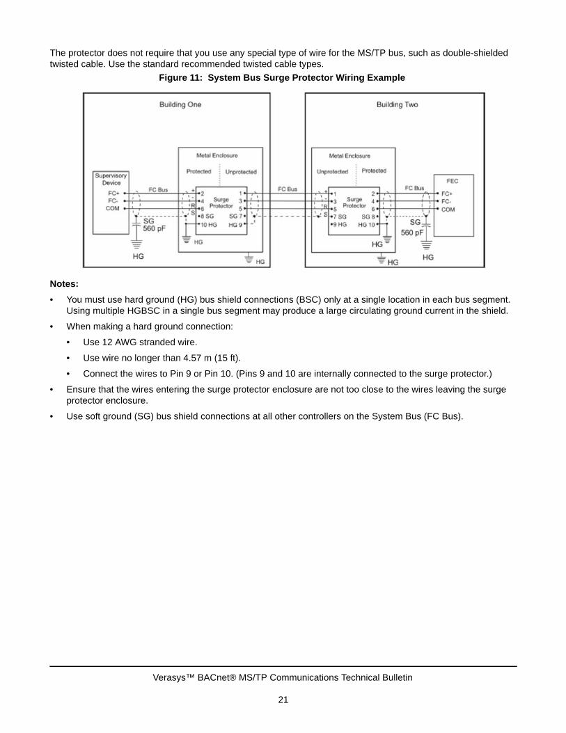
The protector does not require that you use any special type of wire for the MS/TP bus, such as double-shielded twisted cable. Use the standard recommended twisted cable types.
Notes:
• You must use hard ground (HG) bus shield connections (BSC) only at a single location in each bus segment. Using multiple HGBSC in a single bus segment may produce a large circulating ground current in the shield.
• When making a hard ground connection:
• Use 12 AWG stranded wire.
• Use wire no longer than 4.57 m (15 ft).
• Connect the wires to Pin 9 or Pin 10. (Pins 9 and 10 are internally connected to the surge protector.)
• Ensure that the wires entering the surge protector enclosure are not too close to the wires leaving the surge protector enclosure.
• Use soft ground (SG) bus shield connections at all other controllers on the System Bus (FC Bus).
Figure 11: System Bus Surge Protector Wiring Example
Verasys™ BACnet® MS/TP Communications Technical Bulletin
21

The surge protector consists of two sections: the terminal block and the main assembly. These sections separate to make the unit easier to install and replace (Figure 12).
The surge protector is wired depending on which device requires protection. Follow these general steps:
1. Mount the Transient Eliminator device per local codes. Install in an enclosure (if required) as close as possible to the first MS/TP device connecting the trunk segment entering the building. Any electrical box with a cover is acceptable. Bond the transient eliminator enclosure to the MS/TP device enclosure by connecting the two with the conduit that carries the MS/TP cable.
2. Connect the MS/TP segment from the outside to the unprotected side of the device. If possible, run the segment inside metallic conduit because the conduit acts like a shield for lightning.
3. Connect the MS/TP segment that goes to the MS/TP device to the protected side of the device. Keep this segment away from the unprotected segment.
4. Connect the protector to earth ground with 12 AWG stranded green wire (Figure 12). The total length of ground wire cannot exceed 4.57 m (15 ft), which means an earth ground must be available within 4.57 m (15 ft) of the MS/TP device. (Your installation design must accommodate this requirement.)
5. For hard ground installation, connect the shield to Pin 9. For soft ground installation, connect the shield to Pin 7.
For more details on installation, refer to the specific manufacturer’s literature.
Figure 12: Sections of the Surge Protector
Verasys™ BACnet® MS/TP Communications Technical Bulletin
Published in U.S.A. www.johnsoncontrols.com22
Verasys™ and Johnson Controls® are registered trademarks of Johnson Controls.All other marks herein are the marks of their respective owners. © 2017 Johnson Controls.
Building Technologies & Solutions507 E. Michigan Street, Milwaukee, WI 53202
TM