VER. 1.2 Revised - 2017-11-30 BMS COMMUNICATION MCS-BMS ... BMS Communi… · Building Management...
74
MCS Total Solution for all your Control Needs Energy Efficient and RoHS Compliant 5580 Enterprise Pkwy. Fort Myers, FL 33905 Office: 239-694-0089 Fax: 239-694-0031 www.mcscontrols.com BMS COMMUNICATION MCS-BMS-GATEWAY For Interfacing MCS-MAGNUM to Building Automation Systems Protocols MCS, Modbus RTU, Modbus IP, Ethernet, BACnet IP, BACnet MS/TP, LonWorks, Johnson N2 MCS-MAGNUM Ethernet Building Management System MCS-Touch Internet Router MCS-BMS-Gateway RS485 or LonWorks VER. 1.2 Revised - 2017-11-30
Transcript of VER. 1.2 Revised - 2017-11-30 BMS COMMUNICATION MCS-BMS ... BMS Communi… · Building Management...

MCS TotalSolutionfor all yourControlNeeds Energy Efficient and
RoHS Compliant
5580 Enterprise Pkwy.Fort Myers, FL 33905
Office: 239-694-0089Fax: 239-694-0031
www.mcscontrols.com
BMS COMMUNICATIONMCS-BMS-GATEWAY
For Interfacing MCS-MAGNUM toBuilding Automation Systems ProtocolsMCS, Modbus RTU, Modbus IP, Ethernet,
BACnet IP, BACnet MS/TP, LonWorks, Johnson N2
MCS-MAGNUM
Ethernet
Building Management
System
MCS-Touch
Internet Router
MCS-BMS-Gateway
RS485 or LonWorks
VER. 1.2 Revised - 2017-11-30

MCS-MAGNUM-BMS REVISION 1.2
2
The MCS Commitment is to provide practical solutions for the industries needs and to be both a leader and partner in the effective use of
microprocessor controls.
Micro Control Systems, Inc.5580 Enterprise ParkwayFort Myers, Florida 33905
PH:(239) 694-0089 FAX:(239) 694-0031www.mcscontrols.com
All information contained within this document is considered to be proprietary information of Micro Control Systems, Inc. No information or data from this document shall be published, used, reproduced, transmitted, or disclosed to others outside your organization without the prior expressed written consent of Micro Control Systems, Inc. This document and the information contained herein shall be treated as proprietary. Reasonable provisions shall be provided to ensure that this information remains proprietary by your employees, agents, and other personnel that may have access to this document. Copyright ©2017
Date Author Description of Changes4-12-16 DEW Restructured manual
4-14-16 DEW Changes made from Ray
7-8-16 DEW Merge MCS-BMS-GATEWAY VER 2.0
10-03-16 DEW Update drawings, revised back startup section
12-27-16 DEW Creating CSV Files
11-30-17 DEW Remove address 0 in dip switch settings
Revision/Disclaimer Page

MCS-MAGNUM-BMS REVISION 1.2
3
Table of ContentsChapter - 1. BMS Communication Protocols ..................................................................................5
1.1. MCS-Magnum to BMS Connections ............................................................................................................51.2. Sensor Input Points ......................................................................................................................................61.3. Relay Output Points ......................................................................................................................................71.4. Setpoints .......................................................................................................................................................81.5. Chiller/Compressor States ............................................................................................................................81.6. Other Points ..................................................................................................................................................91.7. Network inputs to MCS-Magnum ................................................................................................................121.8. MCS Capacity Control State Chart .............................................................................................................131.9. MCS Compressor Control State Chart .......................................................................................................131.10. MCS-MAGNUM BMS PROTOCOLS ..........................................................................................................14
1.10.1 BACNET OVER IP PROTOCOL .......................................................................................................141.10.2 ETHERNET NETWORK PROTOCOL ..............................................................................................141.10.3 MODBUS RTU PROTOCOL .............................................................................................................151.10.4 MODBUS TCP/IP PROTOCOL .........................................................................................................15
1.11. PROTOCOLS USING MCS-BMS-GATEWAY ............................................................................................15
Chapter - 2. NETWORK PROTOCOLS ................................................................................................162.1. Protocols MCS controllers support: ............................................................................................................162.2. MCS-MAGNUM USING RS-485 ................................................................................................................172.3. Wiring Multiple MCS Controllers .................................................................................................................182.4. MCS-MAGNUM USING ETHERNET .........................................................................................................192.5. EXAMPLE NETWORK ...............................................................................................................................20
2.5.1 Standalone MCS-Magnum ...............................................................................................................202.5.2 MULTIPLE MCS-MAGNUM ENCLOSURES ....................................................................................21
2.6. MULTIPLE MCS-MAGNUM BMS RS485 WIRING DIAGRAM ..................................................................22
Chapter - 1. Introduction ..........................................................................................................................11.1. BTL Mark – BACnet Testing Laboratory ......................................................................................................11.2. LonMarkCertification ....................................................................................................................................11.3. ULandRoHSCerfication ............................................................................................................................1
Chapter - 2. Quick Start Guide ..............................................................................................................2
Chapter - 3. Setup for MCS-BMS-GATEWAY ....................................................................................33.1. RecordIdentificationData ............................................................................................................................33.2. ConfiguringDeviceCommunications ...........................................................................................................3
3.2.1 Set COM settings on all Devices Connected to the MCS-BMS-GATEWAY .......................................33.2.2 Set IP Address for each MCS-MAGNUM connected to the MCS-BMS-GATEWAY ...........................3
3.3. BMS Network Settings: Selecting Stored Configurations, Setting the MAC ...................................... Address, Device Instance, and Baud Rate ...............................................................................................................4
3.3.1 SelectingConfigurationFilesforDevices:“S”BankDIPSwitchesS0–S3 .......................................43.3.2 LonWorks, BACnet MS/TP and N2 .....................................................................................................4Figure 5 Protocol Selection Switch Tables ..........................................................................................................43.3.3 BACnet MS/TP: Setting the MAC Address for BMS Network .............................................................53.3.4 BACnet MS/TP and BACnet/IP: Setting the Device Instance ............................................................63.3.5 Metasys N2: Setting the Node-ID .......................................................................................................63.3.6 BACnet MS/TP: Setting the Serial Baud Rate for BMS Network ........................................................7
3.3.6.1. Baud Rate DIP Switch Selection ...............................................................................................7
Chapter - 4. Interfacing MCS-BMS-GATEWAY to Devices ........................................................84.1. MCS-BMS-GATEWAY Connection Ports ......................................................................................................84.2. Wiring diagram for connecting the MCS-Magnum ........................................................................................94.3. Device Connections to MCS-BMS-GATEWAY ...........................................................................................10

MCS-MAGNUM-BMS REVISION 1.2
4
4.4. MCS-MAGNUM Address Settings ..............................................................................................................114.5. Biasing the RS-485 Device Network ..........................................................................................................134.6. End of Line Termination Switch for the Modbus RS-485 Device Network ..................................................144.8. Power-Up MCS-BMS-GATEWAY ..............................................................................................................154.7. Wiring Field Port to LonWorks Network ......................................................................................................16
Chapter - 5. LonWorks (FPC-C35) ......................................................................................................175.1. Commissioning the MCS-BMS-GATEWAY on a LonWorks network ..........................................................17Field Port to LonWorks ............................................................................................................................................17
5.1.1 InstructionstoDownloadXIFFile(externalinterfacefile) ...............................................................18 from MCS-BMS-GATEWAY FPC-C35 Using Web Browser..............................................................18
Chapter - 6. BACnet/IP SETUP .............................................................................................................206.1. Connecting A PC to the MCS-BMS-GATEWAY .........................................................................................206.3. Connect the PC to MCS-BMS-GATEWAY via the Ethernet Port ................................................................216.2. BACnet/IP: Setting IP Address for Field Network .......................................................................................22
Chapter - 7. Appendix - Troubleshooting .....................................................................................24
Chapter - 8. CREATING CSV FILES USING MCS-CONFIG .......................................................40
Chapter - 9. Reference and Specifications ....................................................................................509.1. Compliance with UL Regulations ................................................................................................................50

MCS-MAGNUM-BMS REVISION 1.2
5
Chapter - 1. BMS Communication ProtocolsThe MCS-Magnum supports as standard: BACnet IP, Modbus RTU, and Modbus TCP/IP protocols.Using the MCS-BMS-GATEWAY, the MCS-Magnum can also support Johnson N2, LonTalk and Bacnet MSTP.Supported baud rates for Modbus RTU and Johnson N2 are 4800bps, 9600bps, 19200bps, 38400bps, and 57600bps.
1.1. MCS-Magnum to BMS Connections

MCS-MAGNUM-BMS REVISION 1.2
6
1.2. Sensor Input PointsSensor numbering is based upon the MCS-MAGNUM or SI16-AO4 hardware type board Notable BACnet properties available: Units
Magnum BACnetID BACnet Name Modbus
Register N2
Sensor M-1 AI: 1 RefertoConfig *30001 *AI: 1
Sensor M-2 AI: 2 RefertoConfig *30002 *AI: 2
Sensor M-3 AI: 3 RefertoConfig *30003 *AI: 3
Sensor M-4 AI: 4 RefertoConfig *30004 *AI: 4
Sensor M-5 AI: 5 RefertoConfig *30005 *AI: 5
Sensor M-6 AI: 6 RefertoConfig *30006 *AI: 6
Sensor M-7 AI: 7 RefertoConfig *30007 *AI: 7
Sensor M-8 AI: 8 RefertoConfig *30008 *AI: 8
Sensor M-9 AI: 9 RefertoConfig *30009 *AI: 9
Sensor M-10 AI:10 RefertoConfig *30010 *AI: 10
Sensor M-11 AI:11 RefertoConfig *30011 *AI: 11
Sensor M-12 AI:12 RefertoConfig *30012 *AI: 12
Sensor M-13 AI:13 RefertoConfig *30013 *AI: 13
Sensor M-14 AI:14 RefertoConfig *30014 *AI: 14
Sensor M-15 AI:15 RefertoConfig *30015 *AI: 15
Sensor M-16 AI:16 RefertoConfig *30016 *AI: 16
Sensor 1-1 AI:17 RefertoConfig *30017 *AI: 17
Sensor 1-2 AI:18 RefertoConfig *30018 *AI: 18
Sensor 1-3 AI:19 RefertoConfig *30019 *AI: 19
Sensor 1-4 AI:20 RefertoConfig *30020 *AI: 20
Sensor 1-5 AI:21 RefertoConfig *30021 *AI: 21
Sensor 1-6 AI:22 RefertoConfig *30022 *AI: 22
Sensor 1-7 AI:23 RefertoConfig *30023 *AI: 23
Sensor 1-8 AI:24 RefertoConfig *30024 *AI: 24
Sensor 1-9 AI:25 RefertoConfig *30025 *AI: 25
Sensor 1-10 AI:26 RefertoConfig *30026 *AI: 26
Sensor 1-11 AI:27 RefertoConfig *30027 *AI: 27
Sensor 1-12 AI:28 RefertoConfig *30028 *AI: 28
Sensor 1-13 AI:29 RefertoConfig *30029 *AI: 29
Sensor 1-14 AI:30 RefertoConfig *30030 *AI: 30
Sensor 1-15 AI:31 RefertoConfig *30031 *AI: 31
Sensor 1-16 AI:32 RefertoConfig *30032 *AI: 32
Sensor 2-1 AI:33 RefertoConfig *30033 *AI: 33
Sensor 2-2 AI:34 RefertoConfig *30034 *AI: 34
Sensor 2-3 AI:35 RefertoConfig *30035 *AI: 35
Sensor 2-4 AI:36 RefertoConfig *30036 *AI: 36
Sensor 2-5 AI:37 RefertoConfig *30037 *AI: 37
Sensor 2-6 AI:38 RefertoConfig *30038 *AI: 38
Sensor 2-7 AI:39 RefertoConfig *30039 *AI: 39
Sensor 2-8 AI:40 RefertoConfig *30040 *AI: 40
Magnum BACnetID BACnet Name Modbus
Register N2
Sensor 2-9 AI:41 RefertoConfig *30041 *AI: 41
Sensor 2-10 AI:42 RefertoConfig *30042 *AI: 42
Sensor 2-11 AI:43 RefertoConfig *30043 *AI: 43
Sensor 2-12 AI:44 RefertoConfig *30044 *AI: 44
Sensor 2-13 AI:45 RefertoConfig *30045 *AI: 45
Sensor 2-14 AI:46 RefertoConfig *30046 *AI: 46
Sensor 2-15 AI:47 RefertoConfig *30047 *AI: 47
Sensor 2-16 AI:48 RefertoConfig *30048 *AI: 48
Sensor 3-1 AI:49 RefertoConfig *30049 *AI:49
Sensor 3-2 AI:50 RefertoConfig *30050 *AI: 50
Sensor 3-3 AI:51 RefertoConfig *30051 *AI: 51
Sensor 3-4 AI:52 RefertoConfig *30052 *AI: 52
Sensor 3-5 AI:53 RefertoConfig *30053 *AI: 53
Sensor 3-6 AI:54 RefertoConfig *30054 *AI: 54
Sensor 3-7 AI:55 RefertoConfig *30055 *AI: 55
Sensor 3-8 AI:56 RefertoConfig *30056 *AI: 56
Sensor 3-9 AI:57 RefertoConfig *30057 *AI: 57
Sensor 3-10 AI:58 RefertoConfig *30058 *AI: 58
Sensor 3-11 AI:59 RefertoConfig *30059 *AI: 59
Sensor 3-12 AI:60 RefertoConfig *30060 *AI: 60
Sensor 3-13 AI:61 RefertoConfig *30061 *AI: 61
Sensor 3-14 AI:62 RefertoConfig *30062 *AI: 62
Sensor 3-15 AI:63 RefertoConfig *30063 *AI: 63
Sensor 3-16 AI:64 RefertoConfig *30064 *AI: 64
Sensor 4-1 AI:65 RefertoConfig *30065 *AI: 65
Sensor 4-2 AI:66 RefertoConfig *30066 *AI: 66
Sensor 4-3 AI:67 RefertoConfig *30067 *AI: 67
Sensor 4-4 AI:68 RefertoConfig *30068 *AI: 68
Sensor 4-5 AI:69 RefertoConfig *30069 *AI: 69
Sensor 4-6 AI:70 RefertoConfig *30070 *AI: 70
Sensor 4-7 AI:71 RefertoConfig *30071 *AI: 71
Sensor 4-8 AI:72 RefertoConfig *30072 *AI: 72
Sensor 4-9 AI:73 RefertoConfig *30073 *AI: 73
Sensor 4-10 AI:74 RefertoConfig *30074 *AI: 74
Sensor 4-11 AI:75 RefertoConfig *30075 *AI: 75
Sensor 4-12 AI:76 RefertoConfig *30076 *AI: 76
Sensor 4-13 AI:77 RefertoConfig *30077 *AI: 77
Sensor 4-14 AI:78 RefertoConfig *30078 *AI: 78
Sensor 4-15 AI:79 RefertoConfig *30079 *AI: 79
Sensor 4-16 AI:80 RefertoConfig *30080 *AI: 80
*- Indicates value multiplied by 10 to include one decimal place. (I.e. BMS value of 500 indicates actual value 50.0)

MCS-MAGNUM-BMS REVISION 1.2
7
1.3. Relay Output PointsRelay Output points are read-only. Output numbering is based upon RO-10 hardware type board
Magnum BACnet ID BACnet Name Modbus N2Relay M–1 BO: 1 Refer to Config 00001 BO: 1Relay M–2 BO: 2 Refer to Config 00002 BO: 2Relay M–3 BO: 3 Refer to Config 00003 BO: 3Relay M–4 BO: 4 Refer to Config 00004 BO: 4Relay M–5 BO: 5 Refer to Config 00005 BO: 5Relay M–6 BO: 6 Refer to Config 00006 BO: 6Relay M–7 BO: 7 Refer to Config 00007 BO: 7Relay M–8 BO: 8 Refer to Config 00008 BO: 8Relay M–9 BO: 9 Refer to Config 00009 BO: 9Relay M-10 BO:10 Refer to Config 00010 BO: 10Relay 1–1 BO:11 Refer to Config 00011 BO: 11Relay 1–2 BO:12 Refer to Config 00012 BO: 12Relay 1–3 BO:13 Refer to Config 00013 BO: 13Relay 1–4 BO:14 Refer to Config 00014 BO: 14Relay 1–5 BO:15 Refer to Config 00015 BO: 15Relay 1–6 BO:16 Refer to Config 00016 BO: 16Relay 1–7 BO:17 Refer to Config 00017 BO: 17Relay 1–8 BO:18 Refer to Config 00018 BO: 18Relay 1–9 BO:19 Refer to Config 00019 BO: 19Relay 1- 10 BO:20 Refer to Config 00020 BO: 20Relay 2–1 BO:21 Refer to Config 00021 BO: 21Relay 2–2 BO:22 Refer to Config 00022 BO: 22Relay 2–3 BO:23 Refer to Config 00023 BO: 23Relay 2–4 BO:24 Refer to Config 00024 BO: 24Relay 2–5 BO:25 Refer to Config 00025 BO: 25Relay 2–6 BO:26 Refer to Config 00026 BO: 26Relay 2–7 BO:27 Refer to Config 00027 BO: 27Relay 2–8 BO:28 Refer to Config 00028 BO: 28Relay 2–9 BO:29 Refer to Config 00029 BO: 29Relay 2 -10 BO:30 Refer to Config 00030 BO: 30Relay 3–1 BO:31 Refer to Config 00031 BO: 31Relay 3–2 BO:32 Refer to Config 00032 BO: 32Relay 3–3 BO:33 Refer to Config 00033 BO: 33Relay 3–4 BO:34 Refer to Config 00034 BO: 34Relay 3–5 BO:35 Refer to Config 00035 BO: 35Relay 3- 6 BO:36 Refer to Config 00036 BO: 36Relay 3–7 BO:37 Refer to Config 00037 BO: 37Relay 3–8 BO:38 Refer to Config 00038 BO: 38Relay 3–9 BO:39 Refer to Config 00039 BO: 39Relay 3–10 BO:40 Refer to Config 00040 BO: 40
Magnum BACnet ID BACnet Name Modbus N2Relay 4–1 BO:41 Refer to Config 00041 BO: 41Relay 4–2 BO:42 Refer to Config 00042 BO: 42Relay 4–3 BO:43 Refer to Config 00043 BO: 43Relay 4–4 BO:44 Refer to Config 00044 BO: 44Relay 4–5 BO:45 Refer to Config 00045 BO: 45Relay 4–6 BO:46 Refer to Config 00046 BO: 46Relay 4–7 BO:47 Refer to Config 00047 BO: 47Relay 4–8 BO:48 Refer to Config 00048 BO: 48Relay 4–9 BO:49 Refer to Config 00049 BO: 49Relay 4 -10 BO:50 Refer to Config 00050 BO: 50Relay 5–1 BO:51 Refer to Config 00051 BO: 51Relay 5–2 BO:52 Refer to Config 00052 BO: 52Relay 5–3 BO:53 Refer to Config 00053 BO: 53Relay 5–4 BO:54 Refer to Config 00054 BO: 54Relay 5–5 BO:55 Refer to Config 00055 BO: 55Relay 5–6 BO:56 Refer to Config 00056 BO: 56Relay 5–7 BO:57 Refer to Config 00057 BO: 57Relay 5–8 BO:58 Refer to Config 00058 BO: 58Relay 5–9 BO:59 Refer to Config 00059 BO: 59Relay 5 -10 BO:60 Refer to Config 00060 BO: 60Relay 6–1 BO:61 Refer to Config 00061 BO: 61Relay 6–2 BO:62 Refer to Config 00062 BO: 62Relay 6–3 BO:63 Refer to Config 00063 BO: 63Relay 6–4 BO:64 Refer to Config 00064 BO: 64Relay 6–5 BO:65 Refer to Config 00065 BO: 65Relay 6- 6 BO:66 Refer to Config 00066 BO: 66Relay 6–7 BO:67 Refer to Config 00067 BO: 67Relay 6–8 BO:68 Refer to Config 00068 BO: 68Relay 6–9 BO:69 Refer to Config 00069 BO: 69Relay 6–10 BO:70 Refer to Config 00760 BO: 70Relay 7–1 BO:71 Refer to Config 00071 BO: 71Relay 7–2 BO:72 Refer to Config 00072 BO: 72Relay 7–3 BO:73 Refer to Config 00073 BO: 73Relay 7–4 BO:74 Refer to Config 00074 BO: 74Relay 7–5 BO:75 Refer to Config 00075 BO: 75Relay 7–6 BO:76 Refer to Config 00076 BO: 76Relay 7–7 BO:77 Refer to Config 00077 BO: 77Relay 7–8 BO:78 Refer to Config 00078 BO: 78Relay 7–9 BO:79 Refer to Config 00079 BO: 79Relay 7–10 BO:80 Refer to Config 00070 BO: 80
*- Indicates value multiplied by 10 to include one decimal place. (I.e. BMS value of 500 indicates actual value 50.0)

MCS-MAGNUM-BMS REVISION 1.2
8
Analog Output Points are read-only. Output numbering is based upon SI16-AO4 hardware type board. Notable BACnet properties available: Units
Magnum BACnet ID BACnet Name Modbus Register N2
Analog Out M-1 AO:1 Refer to Config *30201 *AO: 1
Analog Out M-2 AO:2 Refer to Config *30202 *AO: 2
Analog Out M-3 AO:3 Refer to Config *30203 *AO: 3
Analog Out M-4 AO:4 Refer to Config *30204 *AO: 4
Analog Out 1-1 AO:5 Refer to Config *30205 *AO: 5
Analog Out 1-2 AO:6 Refer to Config *30206 *AO: 6
Analog Out 1-3 AO:7 Refer to Config *30207 *AO: 7
Analog Out 1-4 AO:7 Refer to Config *30208 *AO: 8
Analog Out 2-1 AO:8 Refer to Config *30209 *AO: 9
Analog Out 2-2 AO:10 Refer to Config *30210 *AO: 10
Analog Out 2-3 AO:11 Refer to Config *30211 *AO: 11
Analog Out 2-4 AO:12 Refer to Config *30212 *AO: 12
Analog Out 3-1 AO:13 Refer to Config *30213 *AO: 13
Analog Out 3-2 AO:14 Refer to Config *30214 *AO: 14
Analog Out 3-3 AO:15 Refer to Config *30215 *AO: 15
Analog Out 3-4 AO:16 Refer to Config *30216 *AO: 16
Analog Out 4-1 AO:17 Refer to Config *30217 *AO: 17
Analog Out 4-2 AO:18 Refer to Config *30218 *AO: 18
Analog Out 4-3 AO:19 Refer to Config *30219 *AO: 19
Analog Out 4-4 AO:20 Refer to Config *30220 *AO: 20
*- Indicates value multiplied by 10 to include one decimal place. (I.e. BMS value of 500 indicates actual value 50.0)
1.4. SetpointsSetpoints are read-only. Notable BACnet properties available: Units
Magnum BACnet ID BACnet Name Modbus N2Setpoint #1 AV:0 STP# 1-<Setpoint name> 40301 ADF:1
Setpoint #21 AV:88 STP# 21-<Setpoint name> 40321 ADF:89
Setpoint #163 AV:230 STP# 163-<Setpoint name> 40463 ADF:231
1.5. Chiller/Compressor StatesState values are read-only. Notable BACnet properties available: Number of States, State-Text (Contains character text of current state)
Magnum BACnet ID BACnet Name Modbus Register N2Chiller Unit State MV:0 CHILLER STATE 30306 BYT:1
Compressor #1 State MV:1 COMPRESSOR #1 STATE 30307 BYT:2
Compressor #2 State MV:2 COMPRESSOR #2 STATE 30308 BYT:3

MCS-MAGNUM-BMS REVISION 1.2
9
Magnum BACnet ID BACnet Name Modbus Register N2Compressor #3 State MV:3 COMPRESSOR #3 STATE 30309 BYT:4
Compressor #4 State MV:4 COMPRESSOR #4 STATE 30310 BYT:5
Compressor #5 State MV:5 COMPRESSOR #5 STATE 30311 BYT:6
Compressor #6 State MV:6 COMPRESSOR #6 STATE 30312 BYT:7
Compressor #7 State MV:7 COMPRESSOR #7 STATE 30313 BYT:8
Compressor #8 State MV:8 COMPRESSOR #8 STATE 30314 BYT:9
Compressor #9 State MV:130 COMPRESSOR #9 STATE 30560 BYT:131
Compressor #10 State MV:131 COMPRESSOR #10 STATE 30561 BYT:132
Compressor #11 State MV:132 COMPRESSOR #11 STATE 30562 BYT:133
Compressor #12 State MV:133 COMPRESSOR #12 STATE 30563 BYT:134
Compressor #13 State MV:134 COMPRESSOR #13 STATE 30564 BYT:135
Compressor #14 State MV:135 COMPRESSOR #14 STATE 30565 BYT:136
Compressor #15 State MV:136 COMPRESSOR #15 STATE 30566 BYT:137
Compressor #16 State MV:137 COMPRESSOR #16 STATE 30567 BYT:138
Compressor #17 State MV:138 COMPRESSOR #17 STATE 30568 BYT:139
Compressor #18 State MV:139 COMPRESSOR #18 STATE 30569 BYT:140
Compressor #19 State MV:140 COMPRESSOR #19 STATE 30570 BYT:141
Compressor #20 State MV:141 COMPRESSOR #20 STATE 30571 BYT:142
1.6. Other PointsThese points are read-only.
Magnum BACnet ID BACnet Name Modbus N2Wanted FLA% AV:3 Wanted FLA% 30318 ADF:4Steps Wanted AV:4 Steps Wanted On 30315 ADF:5Steps On AV:5 Steps On 30316 ADF:6Step Delay AV:6 Step Delay 30317 ADF:7Compressor #1 FLA% AV:7 C1_FLA% *30319 *ADF:8Compressor #1 Sat Suction AV:10 C1_Sat Suct *30327 *ADF:11Compressor #1 Sat Disch AV:11 C1_ Sat Disch *30329 *ADF:12Compressor #1 Disch SH AV:12 C1_Disch SH *30330 *ADF:13Compressor #1 Suct SH AV:13 C1_Suct SH *30328 *ADF:14Compressor #1 Oil Pres Diff AV:63 C1_Oil Pres Diff *30375 *ADF:64Compressor #2 FLA% AV:14 C2_FLA% *30320 *ADF:15Compressor #2 Sat Suction AV:17 C2_Sat Suct *30331 *ADF:18Compressor #2 Sat Disch AV:18 C2_ Sat Disch *30333 *ADF:19Compressor #2 Disch SH AV:19 C2_Disch SH *30334 *ADF:20Compressor #2 Suct SH AV:20 C2_Suct SH *30332 *ADF:21Compressor #2 Oil Pres Diff AV:64 C2_Oil Pres Diff *30376 *ADF:65Compressor #3 FLA% AV:21 C3_FLA% *30321 *ADF:22Compressor #3 Sat Suction AV:24 C3_Sat Suct *30335 *ADF:25Compressor #3 Sat Disch AV:25 C3_ Sat Disch *30337 *ADF:26Compressor #3 Disch SH AV:26 C3_Disch SH *30338 *ADF:27Compressor #3 Suct SH AV:27 C3_Suct SH *30336 *ADF:28Compressor #3 Oil Pres Diff AV:65 C3_Oil Pres Diff *30377 *ADF:66Compressor #4 FLA% AV:28 C4_FLA% *30322 *ADF:29Compressor #4 Sat Suction AV:31 C4_Sat Suct *30339 *ADF:32Compressor #4 Sat Disch AV:32 C4_ Sat Disch *30341 *ADF:33

MCS-MAGNUM-BMS REVISION 1.2
10
Magnum BACnet ID BACnet Name Modbus N2Compressor #4 Disch SH AV:33 C4_Disch SH *30342 *ADF:34Compressor #4 Suct SH AV:34 C4_Suct SH *30340 *ADF:35Compressor #4 Oil Pres Diff AV:66 C4_Oil Pres Diff *30378 *ADF:67Compressor #5 FLA% AV:35 C5_FLA% *30323 *ADF:36Compressor #5 Sat Suction AV:38 C5_Sat Suct *30343 *ADF:39Compressor #5 Sat Disch AV:39 C5_ Sat Disch *30345 *ADF:40Compressor #5 Disch SH AV:40 C5_Disch SH *30346 *ADF:41Compressor #5 Suct SH AV:41 C5_Suct SH *30344 *ADF:42Compressor #5 Oil Pres Diff AV:67 C5_Oil Pres Diff *30379 *ADF:68Compressor #6 FLA% AV:42 C6_FLA% *30324 *ADF:43Compressor #6 Sat Suction AV:45 C6_Sat Suct *30347 *ADF:46Compressor #6 Sat Disch AV:46 C6_ Sat Disch *30349 *ADF:47Compressor #6 Disch SH AV:47 C6_Disch SH *30350 *ADF:48Compressor #6 Suct SH AV:48 C6_Suct SH *30348 *ADF:49Compressor #6 Oil Pres Diff AV:68 C6_Oil Pres Diff *30380 *ADF:69Compressor #7 FLA% AV:49 C7_FLA% *30325 *ADF:50Compressor #7 Sat Suction AV:52 C7_Sat Suct *30351 *ADF:53Compressor #7 Sat Disch AV:53 C7_ Sat Disch *30353 *ADF:54Compressor #7 Disch SH AV:54 C7_Disch SH *30354 *ADF:55Compressor #7 Suct SH AV:55 C7_Suct SH *30352 *ADF:56Compressor #7 Oil Pres Diff AV:69 C7_Oil Pres Diff *30381 *ADF:70Compressor #8 FLA% AV:56 C8_FLA% *30326 *ADF:57Compressor #8 Sat Suction AV:59 C8_Sat Suct *30352 *ADF:53Compressor #8 Sat Suction AV:59 C8_Sat Suct *30355 *ADF:60Compressor #8 Sat Disch AV:60 C8_ Sat Disch *30357 *ADF:61Compressor #8 Disch SH AV:61 C8_Disch SH *30358 *ADF:62Compressor #8 Suct SH AV:62 C8_Suct SH *30356 *ADF:63Compressor #8 Oil Pres Diff AV:70 C8_Oil Pres Diff *30382 *ADF:71Compressor #9 FLA% AV:440 C9_FLA% *30572 *ADF:441Compressor #9 Sat Suction AV: 443 C9_Sat Suct *30584 *ADF: 442Compressor #9 Sat Disch AV: 444 C9_ Sat Disch *30586 *ADF: 443Compressor #9 Disch SH AV: 445 C9_Disch SH *30587 *ADF: 444Compressor #9 Suct SH AV: 446 C9_Suct SH *30585 *ADF: 445Compressor #9 Oil Pres Diff AV:524 C9_Oil Pres Diff *30656 *ADF:525Compressor #10 FLA% AV:447 C10_FLA% *30573 *ADF:448Compressor #10 Sat Suction AV: 450 C10_Sat Suct *30588 *ADF: 451Compressor #10 Sat Disch AV: 451 C10_ Sat Disch *30590 *ADF: 452Compressor #10 Disch SH AV: 452 C10_Disch SH *30591 *ADF: 453Compressor #10 Suct SH AV: 453 C10_Suct SH *30589 *ADF: 454Compressor #10 Oil Pres Diff AV:525 C10_Oil Pres Diff *30657 *ADF:526Compressor #11 FLA% AV:454 C11_FLA% *30574 *ADF:455Compressor #11 Sat Suction AV: 457 C11_Sat Suct *30592 *ADF: 458Compressor #11 Sat Disch AV: 458 C11_ Sat Disch *30594 *ADF: 459Compressor #11 Disch SH AV: 459 C11_Disch SH *30595 *ADF: 460Compressor #11 Suct SH AV: 460 C11_Suct SH *30593 *ADF: 461Compressor #11 Oil Pres Diff AV: 526 C11_Oil Pres Diff *30658 *ADF: 527Compressor #12 FLA% AV: 461 C12_FLA% *30575 *ADF: 462Compressor #12 Sat Suction AV: 464 C12_Sat Suct *30596 *ADF: 465Compressor #12 Sat Disch AV: 465 C12_ Sat Disch *30598 *ADF: 466Compressor #12 Disch SH AV: 466 C12_Disch SH *30599 *ADF: 467Compressor #12 Suct SH AV: 467 C12_Suct SH *30597 *ADF 468Compressor #12 Oil Pres Diff AV:527 C12_Oil Pres Diff *30659 *ADF:528

MCS-MAGNUM-BMS REVISION 1.2
11
Magnum BACnet ID BACnet Name Modbus N2Compressor #13 FLA% AV:468 C13_FLA% *30576 *ADF:469Compressor #13 Sat Suction AV: 471 C13_Sat Suct *30600 *ADF: 470Compressor #13 Sat Disch AV: 472 C13_ Sat Disch *30602 *ADF: 473Compressor #13 Disch SH AV: 473 C13_Disch SH *30603 *ADF: 474Compressor #13 Suct SH AV: 474 C13_Suct SH *30600 *ADF: 475Compressor #13 Oil Pres Diff AV: 528 C13_Oil Pres Diff *30661 *ADF: 529Compressor #14 FLA% AV: 475 C14_FLA% *30577 *ADF: 476Compressor #14 Sat Suction AV: 478 C14_Sat Suct *30604 *ADF: 479Compressor #14 Sat Disch AV: 479 C14_ Sat Disch *30606 *ADF: 480Compressor #14 Disch SH AV: 480 C14_Disch SH *30607 *ADF: 481Compressor #14 Suct SH AV: 481 C14_Suct SH *30605 *ADF: 482Compressor #14 Oil Pres Diff AV: 529 C14_Oil Pres Diff *30661 *ADF: 530Compressor #15 FLA% AV: 482 C15_FLA% *30578 *ADF: 483 Compressor #15 Sat Suction AV: 485 C15_Sat Suct *30608 *ADF: 486Compressor #15 Sat Disch AV: 486 C15_ Sat Disch *30610 *ADF: 487Compressor #15 Disch SH AV: 487 C15_Disch SH *30611 *ADF: 488Compressor #15 Suct SH AV: 488 C15_Suct SH *30609 *ADF: 489Compressor #15 Oil Pres Diff AV: 530 C15_Oil Pres Diff *3062 *ADF: 531Compressor #16 FLA% AV: 489 C16_FLA% *30579 *ADF: 490Compressor #16 Sat Suction AV: 492 C16_Sat Suct *30612 *ADF: 493Compressor #16 Sat Disch AV: 493 C16_ Sat Disch *30614 *ADF: 494Compressor #16 Disch SH AV: 494 C16_Disch SH *30615 *ADF: 495Compressor #16 Suct SH AV: 495 C16_Suct SH *30613 *ADF: 496Compressor #16 Oil Pres Diff AV: 531 C16_Oil Pres Diff *30663 *ADF: 532Compressor #17 FLA% AV: 496 C17_FLA% *30580 *ADF: 497Compressor #17 Sat Suction AV: 499 C17_Sat Suct *30616 *ADF: 500Compressor #17 Sat Disch AV: 500 C17_ Sat Disch *30618 *ADF: 501Compressor #17 Disch SH AV: 501 C17_Disch SH *30619 *ADF: 502Compressor #17 Suct SH AV: 502 C17_Suct SH *30617 *ADF: 503Compressor #17 Oil Pres Diff AV: 532 C17_Oil Pres Diff *30664 *ADF: 533Compressor #18 FLA% AV: 503 C18_FLA% *30581 *ADF: 504Compressor #18 Sat Suction AV: 506 C18_Sat Suct *30620 *ADF: 507Compressor #18 Sat Disch AV: 507 C18_ Sat Disch *30622 *ADF: 508Compressor #18 Disch SH AV: 508 C18_Disch SH *30623 *ADF: 509Compressor #18 Suct SH AV: 509 C18_Suct SH *30621 *ADF: 510Compressor #18 Oil Pres Diff AV: 533 C18_Oil Pres Diff *30665 *ADF: 534Compressor #19 FLA% AV: 510 C19_FLA% *30582 *ADF: 511Compressor #19 Sat Suction AV: 513 C19_Sat Suct *30624 *ADF: 514Compressor #19 Sat Disch AV: 514 C19_ Sat Disch *30626 *ADF: 515Compressor #19 Disch SH AV: 515 C19_Disch SH *30627 *ADF: 516Compressor #19 Suct SH AV: 516 C19_Suct SH *30625 *ADF: 517Compressor #19 Oil Pres Diff AV: 534 C19_Oil Pres Diff *30666 *ADF: 535Compressor #20 FLA% AV: 517 C20_FLA% *30583 *ADF: 518Compressor #20 Sat Suction AV: 520 C20_Sat Suct *30628 *ADF: 521Compressor #20 Sat Disch AV: 521 C20_ Sat Disch *30630 *ADF: 522Compressor #20 Disch SH AV: 522 C20_Disch SH *30631 *ADF: 523Compressor #20 Suct SH AV: 523 C20_Suct SH *30629 *ADF: 524Compressor #20 Oil Pres Diff AV: 535 C20_Oil Pres Diff *30667 *ADF: 536
*- Indicates value multiplied by 10 to include one decimal place. (I.e. BMS value of 500 indicates actual value 50.0)

MCS-MAGNUM-BMS REVISION 1.2
12
1.7. Network inputs to MCS-MagnumThe MCS-Magnum can receive changes from the network to enable or disable the Network Run/Stop, Network Target Reset (adjustments to the Cooling Target, Setpoint #1, based on Setpoint #21), Network Demand FLA, and Network Demand Steps.TheMCS-Magnummustbesetuptoaccepttheseinputs.TheconfigurationfilemustcontainaNetworkRun/Stop,Network Target, Network Demand FLA, and Network Demand Steps sensors.
Magnum BACnet ID BACnet Name Modbus N2Network Run/Stop AV:246 Net_R/S 40201 BO:247Network Target/Reset AV:247 Net_Tar/Res 40202 AO:248Network Demand/FLA AV:248 Net_Demad_FLA 40204 AO:249Network Demand/Steps AV:249 Net_Demad_Steps 40205 AO:250
Note the following Information panel has a Network Run/Stop, and /or Network Target Reset sensors inputs indicated. ThisisanexampleofhowMCS-ConfigmustbesetupintheGeneralInformationandEvaporatorInformationpanels.

MCS-MAGNUM-BMS REVISION 1.2
13
The sensors must be set up as follows (This is only an example)
1.8. MCS Capacity Control State ChartThe values exposed in the capacity state relate to the descriptions in this table.
State Number Description0 “UNITINPOWERUP”1 RESERVED2 “NORUN-I/OLOST”3 “UNITINLOCKOUT“4 “UNITISOFF“5 “UNITISHOLDING“6 “UNITUNLOADING“7 “UNITISLOADING“8 “NORUN–SAFETY“9 “RUN/STOPSWOFF“10 “SCHEDULEDOFF“11 “OFF-NOFLOW(s)”
State Number Description20 “SAFETYTRIPPED”21 “LOTEMPUNLOAD”22 “LOTEMPHOLD“23 “HIAMPHOLD“24 “HIDISTMPHLD”25 “CMPISAT40%“26 “CMPISAT70%“27 “HIWATERHOLD“28 “EXTRA70%STEP“29 “OFF-LOOILTMP“30 “HIAMPUNLDING“31 “DEFPREPMPOUT“32 “DEFROSTING“33 “DEFPUMPDOWN“34 “HITEMPUNLOAD“35 “HITEMPHOLD“36 “SCROLLSTEP1“37 “SCROLLSTEP2“38 “SCROLLSTEP3“39 “SCROLLSTEP4“
12 RESERVED13 “AMBIENTOFF“14 “PROCESSHEATOFF”15 “UNITISUNLOADED”16 “UNITISLOADED“17 “OFFTMP-ICEMADE“18 “ECONOMIZERONLY“19 “SWITCHINGMODES“20 “UNITSMOKEUNLDG”21 “UNITOFFUNLDING”22 “UNITDMDUNLDING”23 “UNITHEATUNLDNG”
1.9. MCS Compressor Control State ChartThe values expressed in the compressor state relate to the descriptions in this table.
State Number Description0 “LOSTIOLOCKED”1 “CMPLOCKEDOUT”2 “SWITCHEDOFF“3 “CMPPUMPDOWN“4 “CMPANTICYCLE“5 “CMPOFF/READY“6 “OILPMPLUBING”7 “CMPISRUNNING”8 “CMPUNLOADED“9 “UNLD1/HGBPOFF”10 “PARTLOADED“11 “CMPISHOLDING”12 “CMPISLOADING”13 “CMPISUNLDING”14 “CMPISAT100%”15 “FASTUNLOADING”16 “LOSUCTUNLOAD”17 “LOSUCTHOLD“18 “HIDISCUNLOAD”19 “HIDISCHOLD“

MCS-MAGNUM-BMS REVISION 1.2
14
1.10. MCS-MAGNUM BMS PROTOCOLS
The following Protocols are available with the Magnum. Changes can be made to the settings using the Keypad or can be made using MCS-CONNECT SERVICE WINDOW.
1. BACnet IP2. MCS PROTOCOL3. MODBUS RTU PROTOCOL4. ETHERNET PROTOCOL (this protocol is always active)5. MODBUS IP (this protocol is always active)
1.10.1 BACNET OVER IP PROTOCOLTheBACNETDEVICEIDisafive-digitnumber.ThefirstthreedigitsarebasedonMCS’sBacnetVendorID181, and the last two are set by the Bacnet/MSTP address.
181 XX ↓ ↓ Bacnet Bacnet IP Vendor181 Address
In case the end user would like to set up an ID other than 181-XX, there is an extended BACnet setting that can only be setinMCSConfig.The following changes can be made using the Keypad or can be made using MCS-CONNECT SERVICE WINDOW. The BACnet IPaddresscanbeverifiedandchanged(withtheproperauthorizationcode)fromtheKeypad/LCD.Thefollowing steps will display the Bacnet IP Network address, and the the TCP/IP port:
� Press the Menu key, select Serv Tools, and then press the Enter key. � Use arrow to BACnet Setting then press Enter. � Select address then press Enter. Change the address so it matches the last two digits of the device ID then press
Enter. � Use arrow to tab to the TCP/IP address. � Select address then press Enter. Change the address and port to match your device.
1.10.2 ETHERNET NETWORK PROTOCOLThe following steps will display the ETHERNET NETWORK settings:
If you are going to manually assign the IP Address, Subnet Mask, and Default Gateway. � Press the Menu key, select Serv Tools, and then press the Enter key. � Select Ethernet Network then press Enter. � Set“DYNAMICIP”toNO. � Setthe“IPAddress”. � Setthe“SubnetMask”. � Set“DefaultGateway”. � Reset Magnum for change to take effect.
If you are going to let your network assign the IP Address, Subnet Mask, and Default Gateway: � Press the Menu key, select Serv Tools, and then press the Enter key. � Select Ethernet Network then press Enter. � Set“DYNAMICIP”toYES. � Connect the MCS-Magnum to the network and power up the board.

MCS-MAGNUM-BMS REVISION 1.2
15
1.10.3 MODBUS RTU PROTOCOLTheModbusRTUaddresscanbeverifiedandchanged(withtheproperauthorizationcode)fromthekeypad/LCDorcan be made using MCS-CONNECT SERVICE WINDOW..The following steps will display the Modbus RTU Network address, and the Baud Rate:
� Press the Menu key, select Serv Tools, and then press the Enter key. � Select RS485 Network then press Enter. � Select Protocol then press Enter. Change the protocol to Modbus RTU. � Select address then press Enter. Change the address then press Enter. � Select Baud then press Enter. Set the baud rate then press Enter. � Connect the communication wires to the TX RS485 three-position terminal located above the Ethernet connector. � Reset Magnum for change to take effect.
1.10.4 MODBUS TCP/IP PROTOCOLThis protocol is always active. Make sure the MCS-Magnum network settings are set correctly. If you are going to manually assign the IP Address, Subnet Mask, and Default Gateway. Press the Menu key, select Serv Tools, and then press the Enter key.
� Select Ethernet Network then press Enter. � Set“DYNAMICIP”toNO. � Setthe“IPAddress”. � Setthe“SubnetMask”. � Set“DefaultGateway”. � Reset Magnum for change to take effect.
If you are going to let your network assign the IP Address, Subnet Mask, and Default Gateway: � Press the Menu key, select Serv Tools, and then press the Enter key. � Select Ethernet Network then press Enter. � Set“DYNAMICIP”toYES. � Connect the MCS-Magnum to the network and power up the board.
1.11. PROTOCOLS USING MCS-BMS-GATEWAYThe MCS-BMS-GATEWAY is a microprocessor based communication device that provides translation from BACnet IP to LonTalk, BACnet MSTP, or Johnson Control N2.Information that can be transmitted includes the status of control points, alarm information, digital inputs, ana-log inputs or setpoints.For more information on the MCS-BMS-GATEWAY please go to www.mcscontrols.com.

MCS-MAGNUM-BMS REVISION 1.2
16
Chapter - 2. NETWORK PROTOCOLSNetwork protocols are formatting rules that specify how data is sent and received between devices.Protocols are necessary for devices to interact with each other.
2.1. Protocols MCS controllers support:1. BACNET2. MODBUS RTU3. ETHERNET4. MCS5. LONTALK6. JOHNSON N2
Over Ethernet
Over RS485
Over LonWorks
Requires MCS-BMS-GATEWAY

MCS-MAGNUM-BMS REVISION 1.2
17
2.2. MCS-MAGNUM USING RS-485Using the RS485, the MCS-Magnum can be connected to the BMS (Modbus RTU or MCS 485)
RS485
...
MCS-MAGNUM
MCS-MAGNUM
MCS-MAGNUM
Building Management
System

MCS-MAGNUM-BMS REVISION 1.2
18
2.3. Wiring Multiple MCS Controllers
� Using the RS485, the network must be wired controller to controller
� Starconfigurationsnotallowed
� Up to 30 controllers can be wired together

MCS-MAGNUM-BMS REVISION 1.2
19
2.4. MCS-MAGNUM USING ETHERNET
� Using the Ethernet, the MCS-Magnum can be connected to: � BMS (Bacnet IP or Modbus IP) � MCS-Touch (MCS-Connect) � PC (MCS-Connect)
� Internet access through router (which allows connection via MCS-Connect from anywhere)
Ethernet
Or
Or
Or

MCS-MAGNUM-BMS REVISION 1.2
20
2.5. EXAMPLE NETWORK2.5.1 Standalone MCS-Magnum
� MCS-Touch � BMS (Johnson N2 or LonTalk or Bacnet MSTP) � Internet Access
Ethernet
Building Management
System
MCS-Touch
Internet Router
MCS-BMS-Gateway
RS485 or LonWorks

MCS-MAGNUM-BMS REVISION 1.2
21
2.5.2 MULTIPLE MCS-MAGNUM ENCLOSURES
� Internet Access � BMS (Bacnet IP or Modbus IP)
Ethernet
Rooftop/Chiller #1
Building Management
System
Internet Router
Rooftop/Chiller #2

MCS-MAGNUM-BMS REVISION 1.2
22
2.6. MULTIPLE MCS-MAGNUM BMS RS485 WIRING DIAGRAM

MCS-BMS-GATEWAY Startup Guide REVISION 4.2
23
Chapter - 3. IntroductionMCS-BMS-GATEWAY is an external, high performance Building Automation multi-protocol gateway that has been preprogrammed to support BACnet®1 MS/TP, Metasys®2 N2 by JCI, and LonWorks®3.Configurationsforthe various protocols are stored within the MCS-BMS-GATEWAY and are selectable via DIP switches for fast andeasyinstallation.Itisnotnecessarytodownloadanyconfigurationfilestosupporttherequiredapplications.
This document provides the necessary information to facilitate installation of the MCS-BMS-GATEWAY.
3.1. BTL Mark – BACnet Testing Laboratory
The BTL Mark on the MCS-BMS-GATEWAY is a symbol that indicates to a consumer that a product haspassedaseriesofrigoroustestsconductedbyanindependentlaboratorywhichverifiesthattheproduct correctly implements the BACnet features claimed in the listing. The mark is a symbol of a high-quality BACnet product. Go to http://www.bacnetinternational.net/btl/ for more information about the BACnet Testing Laboratory.
3.2. LonMark Certification
LonMarkInternationalhasdevelopedextensiveproductcertificationstandardsandteststoprovidetheintegratoranduserwithconfidencethatproductsfrommultiplemanufacturersutilizingLonMarkdevicesworktogether.MicroControlSystemshasmoreLonMarkCertifiedgatewaysthananyothergateway manufacturer, including the ProtoCessor, MCS-BMS-GATEWAY and MCS-BMS-GATEWAY forOEMapplicationsandthefullfeatured,configurablegateways.
3.3. UL and RoHS Cerfication
The MCS-BMS GATEWAY is approved across a variety of standards, including the UL 916, CE, and RoHS.
1 BACnet is a registered trademark of ASHRAE2 Metasys is a registered trademark of Johnson Controls Inc.3 LonMark is a registered trademark of LonMark International4 LonWorks is a registered trademark of Echelon Corporation
File No: 916 CE & RoHS

MCS-BMS-GATEWAY Startup Guide REVISION 4.2
24
Chapter - 4. Quick Start Guide1. Record the information about the unit. (Section 3.1)
2. Setthedevice’sBACnetMSTPserialsettings(protocoladdress,baudrate)(Section3.2)
3. SelectastoredconfigurationandsetfieldprotocolMACaddress/Node-ID/DeviceInstance,andbaudrate.(Section 3.3)
4. ConnectMCS-BMS-GATEWAY’s6pinRS-485connectortotheRS-485networkthatisconnectedtoeachofthedevices. (Section 4.2)
5. ConnectMCS-BMS-GATEWAYFPC-C35’s2pinLonWorksporttotheFieldProtocolcablingif connecting by LonWorks (Section 4.7)
6. ConnectPowertoMCS-BMS-GATEWAY’s6pinconnector.(Section4.8)
7. UsetheMCS-BMS-GATEWAY’sembeddedtoolwhichisaccessedwithabrowser,referredtointhismanualastheWebConfigurator,tochangetheIPAddress.Nochangestotheconfigurationfilearenecessary.(Section5)
8. LonWorks (FPC-C35): If LonWorks is selected the MCS-BMS-GATEWAY must be commissioned on the LonWorks Network. This needs to be done by the LonWorks administrator using a LonWorks Commissioning tool. (Section 7)
9. DOWNLOAD FieldServer-Toolbox.zip at www.mcscontrols.com: http://www.mcscontrols.com/Software/BMS%20Tools/FieldServer%20Toolbox%20Setup.zip
Part Number ...............................................................................................
Serial No. ....................................................................................................
PROTOCOL USED BACnet MS/TP LONTALK JOHNSON N2
I/P ADDRESS MCS-BMS-GATEWAY .........................................................
IP ADDRESS MCS-CONTROLLER ...........................................................
SUBNET ADDRESS ...................................................................................
MAGNUM BACnet PORT ...........................................................................
BAUD RATE ...............................................................................................
BACNET ADDRESS USED ........................................................................
FPC-C35
192-168-18- (range 201-250)
192-168-18- (see label on MCS-BMS-GATEWAY)
255-255-255-0 47808 19,200 Default 181, (18100 plus Node setting ‘A’ Bank DIP Switches)
TERMS USED:BACnet - communications protocol for BUILDING AUTOMATION AND CONTROL NETWORKSMAC ADDRESS - MEDIA ACCESS CONTROL ADDRESS (MAC address)LonWorks - PROTOCOL FOR NETWORKING DEVICESBACnet MSTP - COMMUNICATION PROTOCOL FOR BUILDING AUTOMATION TRANSPORTED BY ETHERNETMetasys® N2 - COMMUNICATION PROTOCOL FOR BUILDING AUTOMATION WITH JOHNSON CONTROLS

MCS-BMS-GATEWAY Startup Guide REVISION 4.2
25
Chapter - 5. Setup for MCS-BMS-GATEWAY5.1. Record Identification Data
Each MCS-BMS-GATEWAY has a unique part number located on the side or the back of the unit. This number should be recorded, as it may be required for technical support. The numbers are as follows:
Model Part NumberMCS-BMS-GATEWAY FPC-C35 FPC-C35
Figure 1: MCS-BMS-GATEWAY Part Numbers
• FPC-C35 units have the following 3 ports: LonWorks + Ethernet + RS-485.
5.2. Configuring Device Communications5.2.1 Set COM settings on all Devices Connected to the MCS-BMS-GATEWAY
• SetupalldevicesonthesamesubnetastheMCS-BMS-GATEWAYandtheconfigurationPC.�� All of the connected serial devices MUST have the same Baud Rate, Data Bits, Stop Bits, and Parity settings as the MCS-BMS-GATEWAY.
5.2.2 Set IP Address for each MCS-MAGNUM connected to the MCS-BMS-GATEWAY• ThedeviceneedstobeonthesameIPsubnetastheMCS-BMS-GATEWAYandtheconfiguration
PC.• Record the following MCS-MAGNUM information to start the setup:
�� IP Address�� MCS-MAGNUM BacNet Device ID�� Set MCS-MAGNUM BacNet port to 47808 in MCS-CONFIG
.

MCS-BMS-GATEWAY Startup Guide REVISION 4.2
26
5.3. BMS Network Settings: Selecting Stored Configurations, Setting the MAC Address, Device Instance, and Baud Rate
5.3.1 Selecting Configuration Files for Devices: “S” Bank DIP Switches S0 – S3TheSbankofDIPswitches(S0-S3)areusedtoselectandloadaconfigurationfilefromagroupofpretested/preloadedconfigurationfileswhicharestoredintheMCS-BMS-GATEWAYFPC-C35.
NOTE: S0 - S3 DIP Switches sets the Protocol: BACnet MS/TP, LONTALK, OR JOHNSON N2
NOTE: When setting DIP Switches, please ensure that power to the board is OFF.
5.3.2 LonWorks, BACnet MS/TP and N2ThefollowingchartdescribesS0-S3DIPSwitchconfigurationsettingsforMCS-BMS-GATEWAYtosupportLonWorks, BACnet® MS/TP and Metasys® N2 by JCI
Figure 5 Protocol Selection Switch Tables
S0 – S3 DIP Switches S Bank DIP Switch Location
S0
S1
S2
S3
Off On
Figure 3: S Bank DIP Switches
Fig 3Shows setting for
BACNet MS/TPDip switch S0 ‘ON’ as per the Figure 5
chart below
MCS-BMS-GATEWAY MCS-BMS-GATEWAY Bank DIP SwitchesProfile – MCS-BMS-GATEWAY RER S0 S1 S2 S3Lonworks Off Off Off OffBacnet MS/TP On Off Off OffN2 Off On Off Off

MCS-BMS-GATEWAY Startup Guide REVISION 4.2
27
5.3.3 BACnet MS/TP: Setting the MAC Address for BMS Network• Only 1 MAC address is set for MCS-BMS-GATEWAY regardless of how many devices are connected
to MCS-BMS-GATEWAY.• Set the BACnet MS/TP MAC addresses of the MCS-BMS-GATEWAY to a value between 1 to 127
(MACMasterAddresses);thisissothattheBMSFrontEndcanfindtheMCS-BMS-GATEWAYviaBACnet auto discovery.
NOTE: Never set a BACnet MS/TP MAC Address from 128 to 255. Addresses from 128 to 255 are Slave Addresses and can not be discovered by BMS Front Ends that support auto discovery of BACnet MS/TP devices.
• Set DIP switches A0 – A7 to assign MAC Address for BACnet MS/TP for the MCS-BMS-GATEWAY FPC-C35.
• Please refer to Appendix A.10 for the complete range of MAC Addresses and DIP switch settings.
NOTE: When using Metasys N2 and Modbus TCP/IP, the ‘A’ Bank of DIP switches are disabled and not used. They should be set to OFF.
NOTE: When setting DIP Switches, please ensure that power to the board is OFF.
5.3.4 BACnet MS/TP and BACnet/IP: Setting the Device Instance
A0
A1
A2
A3
A4
A5
A6
A7
Off On
Figure 4: MAC Address DIP Switches
Fig 4Shows setting for 03 BMS Address
as found in A.10 appendixin the rear of this manual

MCS-BMS-GATEWAY Startup Guide REVISION 4.2
28
• The‘A’BankofDIPswitchesareusedfortwopurposes:�� For BACnet MS/TP, they are used to set the BACnet MS/TP MAC address (Section 3.3.2)�� For both BACnet MS/TP and BACnet/IP, they are also used to determine the BACnet Device In-stance values
• The BACnet Device Instance can range from 1 to 4,194,303.• The BACnet device instances will be calculated by taking the Node Offset (default is 18100) found
inWebConfiguratorandaddingittothevalueofthe‘A’BankDIPswitches.
When more than one device is connected to the MCS-BMS-GATEWAY, the subsequent BACnet Device Instance values will be sequential from the first/previous device.
For example: Given that Device Instance = Node_Offset + A Bank DIP switch value
�� Default Node_Offset value = 18100�� ‘A’BankDIPswitchvalue=03(asperAppendixA.10DIPSwitchSetting)
Then the Device Instance values for the devices are:�� Device 1 Instance = 18103�� Device 2 Instance = 18104
5.3.5 Metasys N2: Setting the Node-ID• Set DIP switches A0 – A7 to assign a Node-ID for Metasys N2 to the MCS-BMS-GATEWAY.• Node-ID’srangefrom1-255.• Refer to Appendix A.10 for the full range of addresses for setting Node ID.
5.3.6 BACnet MS/TP: Setting the Serial Baud Rate for BMS Network• DIP Switches B0 – B3 can be used to set the serial baud rate to match the baud rate required by
the Building Management System for BACnet MS/TP. • The baud rate on MCS-BMS-GATEWAY for Metasys N2 is set for 19,200. DIP Switches B0 – B3
are disabled for Metasys N2.NOTE: When setting DIP Switches, please ensure that power to the board is OFF.
B0
B1
B2
B3
Off On
Figure 5: Baud Rate DIP Switches
Fig 5Shows setting for 19200 Baud Rate

MCS-BMS-GATEWAY Startup Guide REVISION 4.2
29
5.3.6.1. Baud Rate DIP Switch Selection
Baud B0 B1 B2 B3
Auto Off Off Off Off
110 On Off Off Off300 Off On Off Off600 On On Off Off
1200 Off Off On Off2400 On Off On Off4800 Off On On Off9600 On On On Off
19200 Off Off Off On20833 On Off Off On28800 Off On Off On38400 On On Off On57600 Off Off On On76800 On Off On On
115200 Off On On On

MCS-BMS-GATEWAY Startup Guide REVISION 4.2
30
Chapter - 6. Interfacing MCS-BMS-GATEWAY to Devices6.1. MCS-BMS-GATEWAY Connection Ports
Figure 7: MCS-BMS-GATEWAY

MCS-BMS-GATEWAY Startup Guide REVISION 4.2
31
6.2. Wiring diagram for connecting the MCS-Magnum
Figure 7 - Gateway to RS-485 wiring

MCS-BMS-GATEWAY Startup Guide REVISION 4.2
32
6.3. Device Connections to MCS-BMS-GATEWAY MCS-BMS-GATEWAY 6 Pin Phoenix connector for RS-485 Devices.
• Pins 1 through 3 are for RS-485 devices.�� The RS-485 GND (Pin 3) is not typically connected
• Pins 4 through 6 are for power. Do not connect power (wait until Section 3.4).
Figure 8: Power and RS-485 Connections
Device Pins MCS-BMS-GATEWAY Pin # Pin Assignment
Pin RS-485 + Pin 1 RS-485 +Pin RS-485 - Pin 2 RS-485 -Pin GND Pin 3 RS-485 GNDPower In (+) Pin 4 V +Power In (-) Pin 5 V -Frame Ground Pin 6 FRAME GND

MCS-BMS-GATEWAY Startup Guide REVISION 4.2
33
6.4. MCS-MAGNUM Address SettingsThe MCS-BMS-GATEWAY is connected to the MCS-MAGNUM via Ethernet . The Bacnet Device ID and the IP address of the MCS-MAGNUM must be setup properly to enable successful communications between the MCS-BMS-GATEWAY and the MCS-MAGNUM.TheMCS-MAGNUMBACNETDEVICEIDmustbesettotheaddressspecifiedontheMCS-BMS-Gateway’slabel (Example - 18103).
TheMCS-MAGNUMBACNETDEVICEIDcanbeverifiedandchanged(withtheproperauthorizationcode)fromMCS-Magnum’skeypadthekeypad/LCDofaliveunit.To get authorized on Magnum do the following:1. Press‘Menu’2. Using , , , or positioncurserto‘Passwords’3. Press key.4. Enter 4 digit password & press .5. Press‘Menu’tomakenextselection.
The following steps will display the Bacnet Device ID:
(to change the address you first must be authorized)
1. Press the MENU key and then Using , , , or position curser to Serv Tools then press the ENTER key.2. then Using , , , or position curser to Bacnet Setting then press Enter.3. Use , , curser to change the Bacnet Device ID.4. Set your desired address then press Enter. 5. Reset or cycle power to the magnum for the change to take effect.
NOTE: This BACNet Device ID will change depending ontheaddressthatwillbesetonthe‘A’DIPSwitches.

MCS-BMS-GATEWAY Startup Guide REVISION 4.2
34
TheMCS-MAGNUMIPmustbesettotheaddressspecifiedontheMCS-BMS-Gateway’slabel(Example - 192.168.18.101). Range of default settings: 101-150
TheMCS-MAGNUMIPaddresscanbeverifiedandchanged(withtheproperauthorizationcode)fromtheMCS-Magnum’sKeypad/LCDofaliveunit.The following steps will display the IP Address settings:(tochangetheaddressyoufirstmustbeauthorized)
1. Press the MENU key and then Using , , , or position curser to Serv Tools then press the ENTER key.
2. Then Using, , or position curser to Serv Tools then press Enter.3. Then Using,, , or position curser to Ethernet Network then press Enter.4. Then Using, , , or position curser to IP address then press Enter.5. Using , toincreaseanddecreasethefirstsetofvaluesthenusethe to select the next set of numbers
and use , to increase and decrease the second value and repeat the previous steps for rest of the ip address.
6. Once you have set the desired address press the Enter key.7. Reset or cycle power to the magnum for the change to take effect.
TheMCS-MAGNUMIPaddresscanbeverifiedandchanged(withtheproperauthorizationcode)fromMCS-CONNECT of a live unit. The following steps will display the IP Address settings:(tochangetheaddressyoufirstmustbeauthorized)
1. Connect to your MCS-Controller thru MCS-CONNECT2. Clickonthe‘SERVICE’tab3. Clickonthe‘ETHERNET’tab4. Make changes to the IP address and any other changes as shown on the MCS-BMS-GATEWAY label.5. Save your changes

MCS-BMS-GATEWAY Startup Guide REVISION 4.2
35
6.5. Biasing the RS-485 Device Network• An RS-485 network with more than one device needs to have biasing to ensure proper communica-
tion. The biasing only needs to be done on one device.• The MCS-BMS-GATEWAY has 510 Ohm resistors that can be used to set the biasing.
TheMCS-BMS-GATEWAY’sdefaultpositionsfromthefactoryfortheBiasingjumpersareOFF.• The OFF position is when the 2 RED biasing jumpers straddle the 4 pins closest to the outside of
the board of the MCS-BMS-GATEWAY. (Figure 9) • Only turn biasing ON:
�� IF the BMS cannot see more than one device connected to the MCS-BMS-GATEWAY AND all the settings (wiring, and DIP switches) have been checked.• To turn biasing ON, move the 2 RED biasing jumpers to straddle the 4 pins closest to the inside of
the board of the MCS-BMS-GATEWAY.
RS-485 Bias Switch
(off)
Figure 9: RS-485 Biasing Switch on the MCS-BMS-GATEWAY

MCS-BMS-GATEWAY Startup Guide REVISION 4.2
36
6.6. End of Line Termination Switch for the Modbus RS-485 Device Network• On long RS-485 cabling runs, the RS-485 trunk must be properly terminated at each end.• The MCS-BMS-GATEWAY has an End of Line (EOL) blue jumper. The default setting for this Blue
EOL switch is OFF with the jumper straddling the pins closest to the inside of the board of the MCS-BMS-GATEWAY.
�� On short cabling runs the EOL switch does not to need to be turned ON• If the MCS-BMS-GATEWAY is placed at one of the ends of the trunk, set the blue EOL jumper to
the ON position straddling the pins closest to the outside of the board of the MCS-BMS-GATEWAY.• Always leave the single Red Jumper in the A position (default factory setting).
RS-485 EOL Switch
(off)
Leave in Position A
Figure 10: Rs-485 End-Of-Line Termination Switch on the MCS-BMS-GATEWAY
MCS-BMS-GATEWAY Startup Guide REVISION 4.2
37
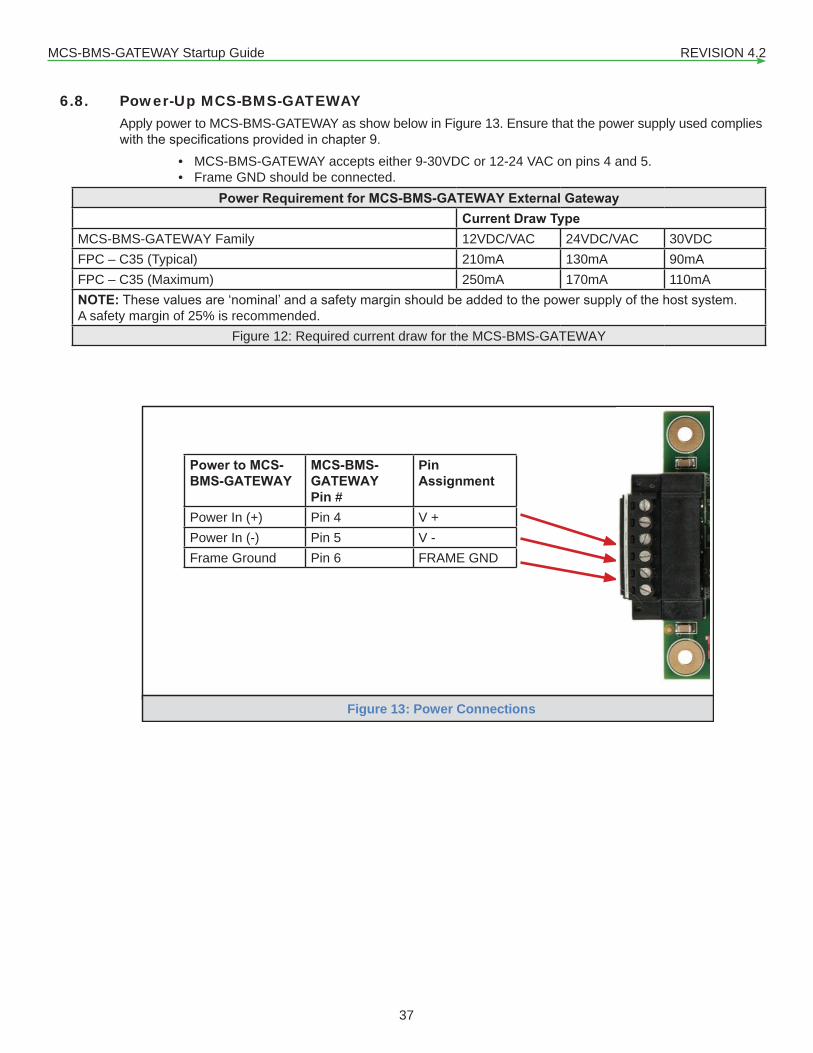
6.8. Power-Up MCS-BMS-GATEWAY Apply power to MCS-BMS-GATEWAY as show below in Figure 13. Ensure that the power supply used complies withthespecificationsprovidedinchapter9.
• MCS-BMS-GATEWAY accepts either 9-30VDC or 12-24 VAC on pins 4 and 5.• Frame GND should be connected.
Power Requirement for MCS-BMS-GATEWAY External Gateway Current Draw TypeMCS-BMS-GATEWAY Family 12VDC/VAC 24VDC/VAC 30VDCFPC – C35 (Typical) 210mA 130mA 90mAFPC – C35 (Maximum) 250mA 170mA 110mANOTE:Thesevaluesare‘nominal’andasafetymarginshouldbeaddedtothepowersupplyofthehostsystem.A safety margin of 25% is recommended.
Figure 12: Required current draw for the MCS-BMS-GATEWAY
Power to MCS-BMS-GATEWAY
MCS-BMS-GATEWAYPin #
PinAssignment
Power In (+) Pin 4 V +Power In (-) Pin 5 V -Frame Ground Pin 6 FRAME GND
Figure 13: Power Connections

MCS-BMS-GATEWAY Startup Guide REVISION 4.2
38
6.7. Wiring Field Port to LonWorks Network• Connect the LonWorks network wires to the 2-pin LonWorks connector on MCS-BMS-GATEWAY
FPC-C35 as shown below in Figure 11.• ConnectMCS-BMS-GATEWAYtothefieldnetworkwiththeLonWorksterminalusingapproved
cable per the FT-10 installation guidelines. LonWorks has no polarity.
BMS LonWorks Wiring
MCS-BMS-GATEWAY Pin #
Pin Assignment
LonWorks Pin 1 LonWorksLonWorks Pin 2 LonWorks
Figure 11: Connection from ProtoCarrier to LonWorks Field Network

MCS-BMS-GATEWAY Startup Guide REVISION 4.2
39
Chapter - 7. LonWorks (FPC-C35) 7.1. Commissioning the MCS-BMS-GATEWAY on a LonWorks network
Commissioning may only be performed by the LonWorks administrator.
1. To commission the MCS-BMS-GATEWAY LonWorks port, press ‘BLUE’ Service Pin 2. This pin is located on the MCS-BMS-GATEWAY top base board. See the illustration below on the MCS-BMS-GATEWAY where the button is located.
NOTE:Inherent to the design of LonWorks is the intention that all nodes residing on a LonWorks network possess aprofilewhichaccuratelydescribesthenetworkvariablesavailabletotheLonWorksnetwork.Thisprofileisdeclared to the LonWorks network by means of an External Interface File (XIF). This XIF remains unchanged foranyparticularprofile.Inotherwords,achangeintheXIFisbydefinitionanewprofile.3. IfanXIFfileisrequired,seestepsinnextsectiontogenerateXIF.
LonWorks‘BLUE’ServicePin
Field Port to LonWorks
1

MCS-BMS-GATEWAY Startup Guide REVISION 4.2
40
7.1.1 Instructions to Download XIF File (external interface file) from MCS-BMS-GATEWAY FPC-C35 Using Web Browser
Connect a CAT5 Ethernet cable (Straight through or Cross-Over) between the PC and MCS-BMS-GATEWAY.The Default IP Address of MCS-BMS-GATEWAY is 192.168.18.201, Subnet Mask is 255.255.255.0. If the PC and MCS-BMS-GATEWAY are on different IP Networks, assign a static IP Address to the PC on the 192.168.18.XXX network.
• For Windows XP:
• For Windows XP and Windows 7, select: Use the following IP Address
• Open a web browser and go to the following address: [IP Address of MCS-BMS-GATEWAY]/fserver.xif�� Example: 192.168.10.201/fserver.xif
• Ifthewebbrowserpromptstosavethefile,savethefileontothePC.Ifthewebbrowserdisplaysthexiffileasawebpage,savethefileontothelocalPCasfserver.xif
*Customer ProtoCarrier Startup Guide
Page 23 of 38
6 LONWORKS (FPC-C35): COMMISSIONING PROTOCARRIER ON A LONWORKS NETWORK
Commissioning may only be performed by the LonWorks administrator.
6.1 Commissioning ProtoCarrier FPC-C35 on a LonWorks Network
The User will be prompted by the LonWorks Administrator to hit the Service Pin on the ProtoCarrier FPC-C35 at the correct step of the Commissioning process which is different for each LonWorks Network Management Tool.
If an XIF file is required, see steps in Section 6.1.1 to generate XIF.
6.1.1 Instructions to Download XIF File from ProtoCarrier FPC-C35 Using Browser
Connect a CAT5 Ethernet cable (Straight through or Cross-Over) between the PC and ProtoCarrier.
The Default IP Address of ProtoCarrier is 192.168.1.24, Subnet Mask is 255.255.255.0. If the PC and ProtoCarrier are on different IP Networks, assign a static IP Address to the PC on the 192.168.1.xxx network.
For Windows XP:
Go to > >
Right-click on Local Area Connection > Properties
Highlight >
For Windows 7 or later:
Go to > >
> >
Right-click on Local Area Connection > Properties
Highlight >
Figure 17: LonWorks Service Pin Location
192 . 168 . 18 . 201
255 . 255 . 255 . 0
192 . 168 . 18 . 1
*Customer ProtoCarrier Startup Guide
Page 24 of 38
For Windows XP and Windows 7, select: Use the following IP Address
Click twice
Open a web browser and go to the following address: [IP Address of ProtoCarrier]/fserver.xif
o Example: 192.168.1.24/fserver.xif
If the web browser prompts to save the file, save the file onto the PC. If the web browser displays the xif file as a web page, save the file onto the local PC as fserver.xif
Figure 18: Sample of Fserver.XIF File Being Generated

MCS-BMS-GATEWAY Startup Guide REVISION 4.2
41
Figure 18: Sample of Fserver.XIF File Being Generated
NOTE:Theexternalinterfacefile(.XIF)fortheFieldServercanbeuploadedfromtheFieldServerfortheparticularapplication.TheFieldServerdiffersfrommostotherLonWorksdevicesinthatitsXIFfileisnotfixedduetovarying applications. The list of points available to the network will vary depending on the other networks connected to the FieldServer, and the requirements of the particular application.

MCS-BMS-GATEWAY Startup Guide REVISION 4.2
42
Chapter - 8. BACnet/IP SETUP8.1. Connecting A PC to the MCS-BMS-GATEWAY
• Confirmthatthenetworkcablingiscorrect• Confirmthatthecomputernetworkcardisoperationalandcorrectlyconfigured• ConfirmthatthereisanEthernetadapterinstalledinthePC’sDeviceManagerList,andthatitis
configuredtoruntheTCP/IPprotocol• Check that the IP netmask of the PC matches the MCS-BMS-GATEWAY. The Default IP Address of
the MCS-BMS-GATEWAY is 192.168.18.201, Subnet Mask is 255.255.255.0, Default Gateway is 192.168.18.1.
• Go to Start > Run• Typein“ipconfig”• The account settings should be displayed• Ensure that the IP address is 192.168.18.xxx, the Subnet mask is 255.255.255.0 and the Default Gateway is 192.168.18.1• Ensure that the PC and MCS-BMS-GATEWAY are on the same IP Network, or assign a Static IP Address
to the PC on the 192.168.18.XXX network• IfUsingWindowsXP,ensurethatthefirewallisdisabled• Ensure that all other Ethernet cards active on the PC, especially wireless adapters are disabled

MCS-BMS-GATEWAY Startup Guide REVISION 4.2
43
8.3. Connect the PC to MCS-BMS-GATEWAY via the Ethernet Port• Connect a CAT5 Ethernet cable (Straight through or Cross-Over) between the local PC and
MCS-BMS-GATEWAY.• The Default IP Address of MCS-BMS-GATEWAY is 192.168.18.201 (range 201-250), Subnet Mask
is 255.255.255.0. If the PC and MCS-BMS-GATEWAY are on different IP Networks, assign a static IP Address to the PC on the 192.168.18.XXX network.
• For Windows XP:
Go to > >
Right-click on Local Area Connection > Properties
> thgilhgiH
For Windows 7 or later:
> > ot oG
> >
Right-click on Local Area Connection > Properties
> thgilhgiH
For Windows XP and Windows 7, use the following IP Address:
Click twice.
192 . 168 . 18 . XXX
255 . 255 . 255 . 0
NetworkConnections
192 . 168 . 18 . 1
MCS-BMS-GATEWAY RANGE201-250
use an address that will not conflict with
these numbers

MCS-BMS-GATEWAY Startup Guide REVISION 4.2
44
8.2. BACnet/IP: Setting IP Address for Field Network• After setting a local PC on the same subnet as the MCS-BMS-GATEWAY (Section 4.1), open a
web browser on the PC and enter the IP Address of the MCS-BMS-GATEWAY; the address is shownonthelabelaffixedtoyourMCS-BMS-GATWAY192.168.10.XXX(range201-250)
NOTE: IftheIPAddressoftheMCS-BMS-GATEWAYhasbeenchangedbypreviousconfiguration,theassigned IP Address can be discovered using the FieldServer Toolbox utility. See Section Appendix A.1 for instructions.
• TheWebConfiguratorwillbedisplayedasthelandingpage.(Figure14)
Figure14:WebConfigurationScreen

MCS-BMS-GATEWAY Startup Guide REVISION 4.2
45
• FromtheWebGUIlandingpage,clickon“Setup”toexpandthenavigationtreeandthenselect“NetworkSettings”toaccesstheIPSettingsmenu.(Figure15)
Figure 15: Changing IP Address via Web GUI
• EnterthenewIPAddressfortheMCS-BMS-GATEWAY’sEthernetportinthe“N1IPAddress”field.• Ifnecessary,changetheSubnetMasksettinginthe“N1Netmask”field.• Ifnecessary,changetheIPGatewaysettinginthe“DefaultGateway”field.
NOTE: If the MCS-BMS-GATEWAY is connected to a router, the IP Gateway of the MCS-BMS-GATEWAY should be set to the IP Address of that router.
• Clickthe“SystemRestart”buttonatthebottomofthepagetoapplychangesandrestartthe MCS-BMS-GATEWAY.
• Unplug Ethernet cable from PC and connect the MCS-BMS-GATEWAY to the network hub or router.
• Record the IP Address assigned to the MCS-BMS-GATEWAY for future reference.
MCS-BMS-GATEWAY Startup Guide REVISION 4.2
46
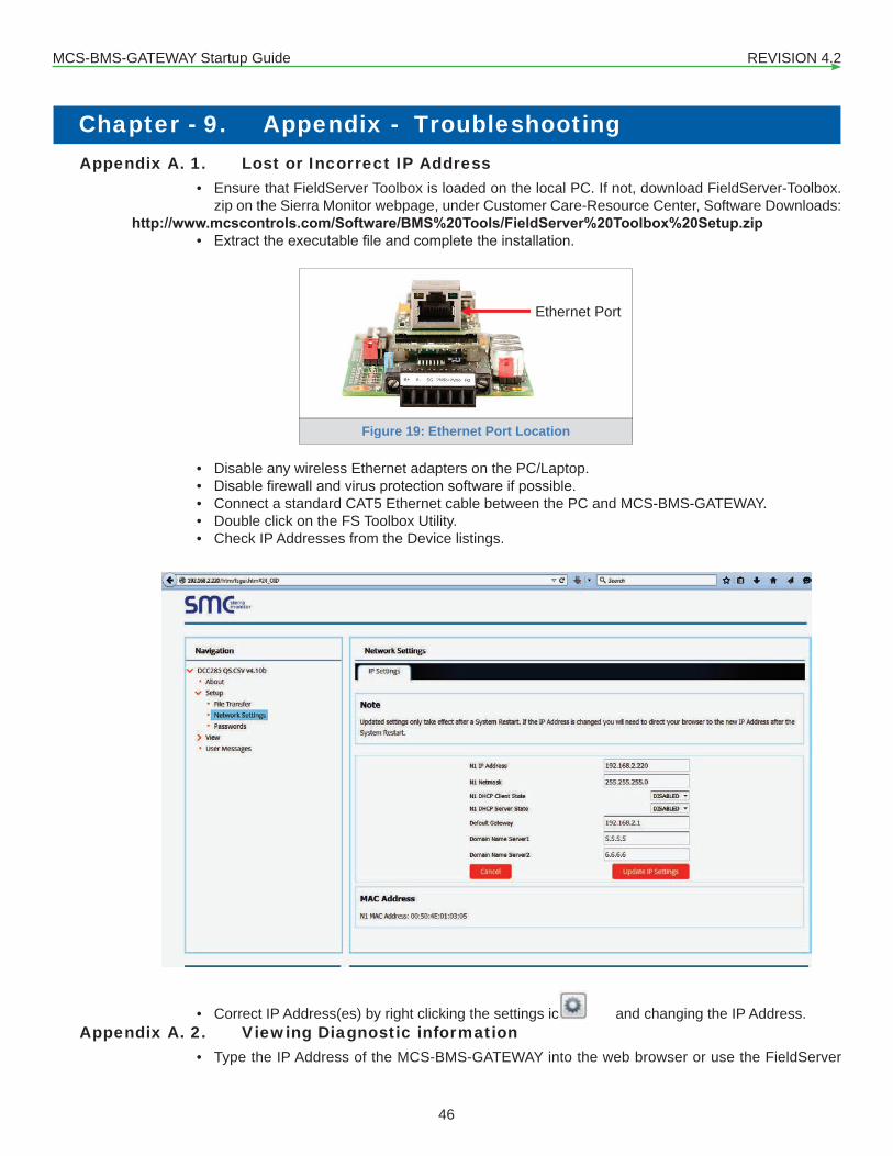
Chapter - 9. Appendix - Troubleshooting Appendix A. 1. Lost or Incorrect IP Address
• Ensure that FieldServer Toolbox is loaded on the local PC. If not, download FieldServer-Toolbox.zip on the Sierra Monitor webpage, under Customer Care-Resource Center, Software Downloads:
http://www.mcscontrols.com/Software/BMS%20Tools/FieldServer%20Toolbox%20Setup.zip• Extracttheexecutablefileandcompletetheinstallation.
• Disable any wireless Ethernet adapters on the PC/Laptop.• Disablefirewallandvirusprotectionsoftwareifpossible.• Connect a standard CAT5 Ethernet cable between the PC and MCS-BMS-GATEWAY. • Double click on the FS Toolbox Utility.• Check IP Addresses from the Device listings.
• Correct IP Address(es) by right clicking the settings icon and changing the IP Address.Appendix A. 2. Viewing Diagnostic information
• Type the IP Address of the MCS-BMS-GATEWAY into the web browser or use the FieldServer
*Customer ProtoCarrier Startup Guide
Page 25 of 38
Appendix A. Troubleshooting
Appendix A.1. Lost or Incorrect IP Address
Ensure that FieldServer Toolbox is loaded on the local PC. If not, download FieldServer-Toolbox.zip on the Sierra Monitor webpage, under Customer Care-Resource Center, Software Downloads: http://www.sierramonitor.com/customer-care/resource-center?filters=software-downloads
Extract the executable file and complete the installation.
Disable any wireless Ethernet adapters on the PC/Laptop.
Disable firewall and virus protection software if possible.
Connect a standard CAT5 Ethernet cable between the PC and ProtoCarrier.
Double click on the FS Toolbox Utility.
Check IP Addresses from the Device listings.
Correct IP Address(es) by right clicking the settings icon and changing the IP Address.
Figure 19: Ethernet Port Location
Ethernet Port

MCS-BMS-GATEWAY Startup Guide REVISION 4.2
47
Toolbox to connect to the MCS-BMS-GATEWAY.• Click on Diagnostics and Debugging Button , then click on view, and then on connections.• If there are any errors showing on the Connection page, please refer to section for the relevant
wiring and settings.Figure 20: Error messages screen
Appendix A. 3. Check Wiring and Settings• NoCOMSonN2.IftheTx/RxLEDsarenotflashingrapidlythenthereisaCOMissue.Tofixthis
problem, check the following:�� Visual observations of LEDs on MCS-BMS-GATEWAY (Appendix A.5)�� Check baud rate, parity, data bits, stop bits�� Check BacNet MSTP device address�� Verify wiring�� Verify BacNet MSTP device is connected to the same subnet as the MCS-BMS-GATEWAY�� Verify BacNet MSTPdevicewasdiscoveredinWebConfigurator
• NoCOMSonTCP/IPsidetotheMCS-MAGNUM.Tofixthisproblemcheckthefollowing:�� Device IP setting�� Verify wiring�� Verify MCS-MAGNUM is connected to the same subnet as the MCS-BMS-GATEWAY
NOTE: If the problem still exists, a Diagnostic Capture needs to be taken and sent to support. (Appendix A.6)
Appendix A. 4. No communication between the MCS-Magnum and the MCS-BMS-GATEWAY
• Confirmthatthenetworkcablingiscorrect• Check that the IP address, subnet mask, and the default gateway of the MCS-Magnum match what the

MCS-BMS-GATEWAY Startup Guide REVISION 4.2
48
label on the MCS-BMS-GATEWAY says it should be set to. • ChecktheLED’sontheEthernetport.TheyellowLEDshouldbesolidyellowthegreenLEDshould
continuouslyflash.
• LED Diagnostics for Lonworks Communications between the MCS-BMS-GATEWAY and device Note: Please see the diagram below for LED Locations
Appendix A. 5. LED Diagnostics for Communications Between MCS-BMS-GATEWAY and Devices
Please see the diagram below for LED locations to MCS-BMS-GATEWAY FPC-C35.
Yellow LED Green LED
Ethernet Port

MCS-BMS-GATEWAY Startup Guide REVISION 4.2
49
Tag DescriptionSPL TheSPLLEDwilllightiftheunitisnotgettingaresponsefromoneormoreoftheconfigureddevices.
For LonWorks units, LED will light until the unit is commissioned on the LonWorks network.RUN TheRUNLEDwillstartflashing20secondsafterpowerindicatingnormaloperation.ERR The SYS ERR LED will go on solid 15 seconds after power up. It will turn off after 5 seconds. A steady red light
willindicatethereisasystemerroronunit.Ifthisoccurs,immediatelyreporttherelated“systemerror”showninthe error screen of the GUI interface to support for evaluation.
RX If socket protocol is serial,theRXLEDwillflashwhenamessageisreceivedonthehostport.If socket protocol is Ethernet, this LED is not used.
TX If socket protocol is serial,theTXLEDwillflashwhenamessageissentonthehostport.If socket protocol is Ethernet, this LED is not used.
PWR This is the power light and should show steady green at all times when the unit is powered.Figure 21: Diagnostic LEDs

MCS-BMS-GATEWAY Startup Guide REVISION 4.2
50
Appendix A. 6. Take Diagnostic Capture With the FieldServer Toolbox• Once the Diagnostic Capture is complete, email it to [email protected]. The Diagnostic
Capture will accelerate diagnosis of the problem.• Ensure that FieldServer Toolbox is Loaded on the PC that is currently being used, or download
http://www.mcscontrols.com/Software/BMS%20Tools/FieldServer%20Toolbox%20Setup.zip• Extracttheexecutablefileandcompletetheinstallation.• Disable any wireless Ethernet adapters on the PC/Laptop.
• Disablefirewallandvirusprotectionsoftwareifpossible.• Connect a standard CAT5 Ethernet cable between the PC and MCS-BMS-GATEWAY.• Double click on the FS Toolbox Utility.• Step 1: Take a Log
�� Click on the diagnose icon of the desired device.
*Customer ProtoCarrier Startup Guide
Page 29 of 38
Appendix A.5. Take Diagnostic Capture With the FieldServer Toolbox
Once the Diagnostic Capture is complete, email it to [email protected]. The Diagnostic Capture will accelerate diagnosis of the problem.
Ensure that FieldServer Toolbox is Loaded on the PC that is currently being used, or download FieldServer-Toolbox.zip on the Sierra Monitor Corporation webpage, under Customer Care- Resource Center, Software Downloads: http://www.sierramonitor.com/customer-care/resource-center?filters=software-downloads
Extract the executable file and complete the installation.
Disable any wireless Ethernet adapters on the PC/Laptop.
Disable firewall and virus protection software if possible.
Connect a standard CAT5 Ethernet cable between the PC and ProtoCarrier.
Double click on the FS Toolbox Utility.
Step 1: Take a Log
o Click on the diagnose icon of the desired device.
Figure 22: Ethernet Port Location
Ethernet Port

MCS-BMS-GATEWAY Startup Guide REVISION 4.2
51
Select full Diagnostic.
NOTE: If desired, the default capture period can be changed. �� Clickon“StartDiagnostic”.
�� WaitforCaptureperiodtofinish.DiagnosticTestCompletewindowwillappear.

MCS-BMS-GATEWAY Startup Guide REVISION 4.2
52
• Step 2: Send Log�� OncetheDiagnostictestiscomplete,a.zipfilewillbesavedonthePC.
�� Choose“Open”tolaunchexplorerandhaveitpointdirectlyatthecorrectfolder�� [email protected]

MCS-BMS-GATEWAY Startup Guide REVISION 4.2
53
Appendix A. 7. Fire Transfer - Load New CSV file1. Toloadanewconfiguration,followtheseinstructions:2. FollowinstructionsinChapter8tocreateanewCSVfile3. Open a web browser and type the IP Address of the FieldServer in the address bar.4. NOTE: Default IP Address is 192.168.18.201 (range 201-250)5. NOTE: Use the FS Toolbox utility if the IP Address is unknown (Appendix A.1).6. Locateyourdevice,clickon‘CONNECT’.7. In the Navigation Tree on the left hand side, do the following:8. Clickon“Setup”9. Clickon“FileTransfer”10. Clickonthe“Configuration”tab11. Intheconfigurationtab,clickon“ChooseFiles”andselecttheCSVfileextractedinstep2.12. Clickontheorange“Submit”button.13. Whenthedownloadiscomplete,clickonthe“SystemRestart”button.
MCS-BMS-GATEWAY Startup Guide REVISION 4.2
54
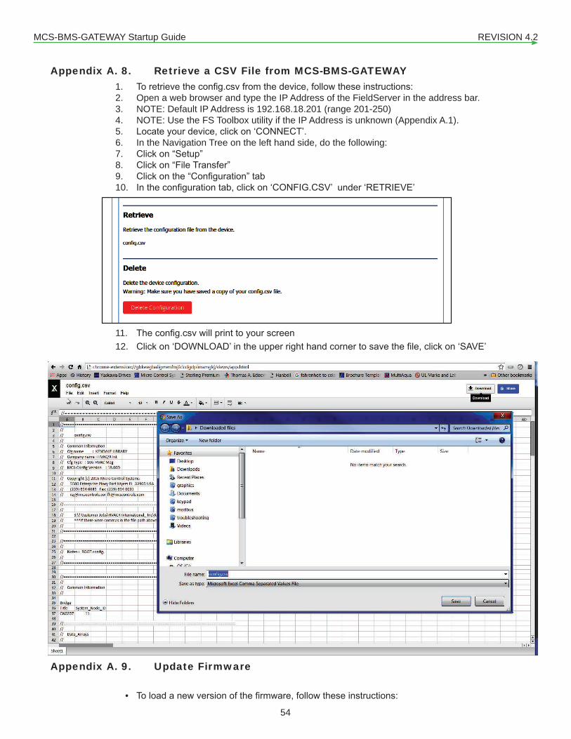
Appendix A. 8. Retrieve a CSV File from MCS-BMS-GATEWAY1. Toretrievetheconfig.csvfromthedevice,followtheseinstructions:2. Open a web browser and type the IP Address of the FieldServer in the address bar.3. NOTE: Default IP Address is 192.168.18.201 (range 201-250)4. NOTE: Use the FS Toolbox utility if the IP Address is unknown (Appendix A.1).5. Locateyourdevice,clickon‘CONNECT’.6. In the Navigation Tree on the left hand side, do the following:7. Clickon“Setup”8. Clickon“FileTransfer”9. Clickonthe“Configuration”tab10. Intheconfigurationtab,clickon‘CONFIG.CSV’under‘RETRIEVE’
11. Theconfig.csvwillprinttoyourscreen12. Clickon‘DOWNLOAD’intheupperrighthandcornertosavethefile,clickon‘SAVE’
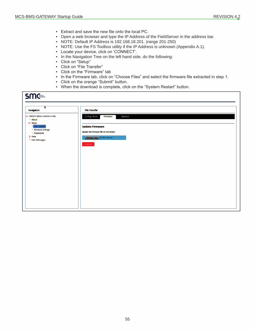
Appendix A. 9. Update Firmware
• Toloadanewversionofthefirmware,followtheseinstructions:
MCS-BMS-GATEWAY Startup Guide REVISION 4.2
55
• ExtractandsavethenewfileontothelocalPC.• Open a web browser and type the IP Address of the FieldServer in the address bar.• NOTE: Default IP Address is 192.168.18.201. )range 201-250)• NOTE: Use the FS Toolbox utility if the IP Address is unknown (Appendix A.1).• Locateyourdevice,clickon‘CONNECT’.• In the Navigation Tree on the left hand side, do the following:• Clickon“Setup”• Clickon“FileTransfer”• Clickonthe“Firmware”tab• IntheFirmwaretab,clickon“ChooseFiles”andselectthefirmwarefileextractedinstep1.• Clickontheorange“Submit”button.• Whenthedownloadiscomplete,clickonthe“SystemRestart”button.

MCS-BMS-GATEWAY Startup Guide REVISION 4.2
56
Appendix A. 10. BMS Address DIP Switch Settings
A7 A6 A5 A4 A3 A2 A1 A0 AddressOff Off Off Off Off Off Off On 1Off Off Off Off Off Off On Off 2Off Off Off Off Off Off On On 3Off Off Off Off Off On Off Off 4Off Off Off Off Off On Off On 5Off Off Off Off Off On On Off 6Off Off Off Off Off On On On 7Off Off Off Off On Off Off Off 8Off Off Off Off On Off Off On 9Off Off Off Off On Off On Off 10Off Off Off Off On Off On On 11Off Off Off Off On On Off Off 12Off Off Off Off On On Off On 13Off Off Off Off On On On Off 14Off Off Off Off On On On On 15Off Off Off On Off Off Off Off 16Off Off Off On Off Off Off On 17Off Off Off On Off Off On Off 18Off Off Off On Off Off On On 19Off Off Off On Off On Off Off 20Off Off Off On Off On Off On 21Off Off Off On Off On On Off 22Off Off Off On Off On On On 23Off Off Off On On Off Off Off 24Off Off Off On On Off Off On 25Off Off Off On On Off On Off 26Off Off Off On On Off On On 27Off Off Off On On On Off Off 28Off Off Off On On On Off On 29Off Off Off On On On On Off 30Off Off Off On On On On On 31Off Off On Off Off Off Off Off 32Off Off On Off Off Off Off On 33Off Off On Off Off Off On Off 34Off Off On Off Off Off On On 35Off Off On Off Off On Off Off 36Off Off On Off Off On Off On 37Off Off On Off Off On On Off 38Off Off On Off Off On On On 39Off Off On Off On Off Off Off 40Off Off On Off On Off Off On 41

MCS-BMS-GATEWAY Startup Guide REVISION 4.2
57
A7 A6 A5 A4 A3 A2 A1 A0 AddressOff Off On Off On Off On Off 42Off Off On Off On Off On On 43Off Off On Off On On Off Off 44Off Off On Off On On Off On 45Off Off On Off On On On Off 46Off Off On Off On On On On 47Off Off On On Off Off Off Off 48Off Off On On Off Off Off On 49Off Off On On Off Off On Off 50Off Off On On Off Off On On 51Off Off On On Off On Off Off 52Off Off On On Off On Off On 53Off Off On On Off On On Off 54Off Off On On Off On On On 55Off Off On On On Off Off Off 56Off Off On On On Off Off On 57Off Off On On On Off On Off 58Off Off On On On Off On On 59Off Off On On On On Off Off 60Off Off On On On On Off On 61Off Off On On On On On Off 62Off Off On On On On On On 63Off On Off Off Off Off Off Off 64Off On Off Off Off Off Off On 65Off On Off Off Off Off On Off 66Off On Off Off Off Off On On 67Off On Off Off Off On Off Off 68Off On Off Off Off On Off On 69Off On Off Off Off On On Off 70Off On Off Off Off On On On 71Off On Off Off On Off Off Off 72Off On Off Off On Off Off On 73Off On Off Off On Off On Off 74Off On Off Off On Off On On 75Off On Off Off On On Off Off 76Off On Off Off On On Off On 77Off On Off Off On On On Off 78Off On Off Off On On On On 79Off On Off On Off Off Off Off 80Off On Off On Off Off Off On 81Off On Off On Off Off On Off 82Off On Off On Off Off On On 83Off On Off On Off On Off Off 84

MCS-BMS-GATEWAY Startup Guide REVISION 4.2
58
A7 A6 A5 A4 A3 A2 A1 A0 AddressOff On Off On Off On On Off 86Off On Off On Off On On On 87Off On Off On On Off Off Off 88Off On Off On On Off Off On 89Off On Off On On Off On Off 90Off On Off On On Off On On 91Off On Off On On On Off Off 92Off On Off On On On Off On 93Off On Off On On On On Off 94Off On Off On On On On On 95Off On On Off Off Off Off Off 96Off On On Off Off Off Off On 97Off On On Off Off Off On Off 98Off On On Off Off Off On On 99Off On On Off Off On Off Off 100Off On On Off Off On Off On 101Off On On Off Off On On Off 102Off On On Off Off On On On 103Off On On Off On Off Off Off 104Off On On Off On Off Off On 105Off On On Off On Off On Off 106Off On On Off On Off On On 107Off On On Off On On Off Off 108Off On On Off On On Off On 109Off On On Off On On On Off 110Off On On Off On On On On 111Off On On On Off Off Off Off 112Off On On On Off Off Off On 113Off On On On Off Off On Off 114Off On On On Off Off On On 115Off On On On Off On Off Off 116Off On On On Off On Off On 117Off On On On Off On On Off 118Off On On On Off On On On 119Off On On On On Off Off Off 120Off On On On On Off Off On 121Off On On On On Off On Off 122Off On On On On Off On On 123Off On On On On On Off Off 124Off On On On On On Off On 125Off On On On On On On Off 126Off On On On On On On On 127On Off Off Off Off Off Off Off 128

MCS-BMS-GATEWAY Startup Guide REVISION 4.2
59
A7 A6 A5 A4 A3 A2 A1 A0 AddressOn Off Off Off Off Off Off On 129On Off Off Off Off Off On Off 130On Off Off Off Off Off On On 131On Off Off Off Off On Off Off 132On Off Off Off Off On Off On 133On Off Off Off Off On On Off 134On Off Off Off Off On On On 135On Off Off Off On Off Off Off 136On Off Off Off On Off Off On 137On Off Off Off On Off On Off 138On Off Off Off On Off On On 139On Off Off Off On On Off Off 140On Off Off Off On On Off On 141On Off Off Off On On On Off 142On Off Off Off On On On On 143On Off Off On Off Off Off Off 144On Off Off On Off Off Off On 145On Off Off On Off Off On Off 146On Off Off On Off Off On On 147On Off Off On Off On Off Off 148On Off Off On Off On Off On 149On Off Off On Off On On Off 150On Off Off On Off On On On 151On Off Off On On Off Off Off 152On Off Off On On Off Off On 153On Off Off On On Off On Off 154On Off Off On On Off On On 155On Off Off On On On Off Off 156On Off Off On On On Off On 157On Off Off On On On On Off 158On Off Off On On On On On 159On Off On Off Off Off Off Off 160On Off On Off Off Off Off On 161On Off On Off Off Off On Off 162On Off On Off Off Off On On 163On Off On Off Off On Off Off 164On Off On Off Off On Off On 165On Off On Off Off On On Off 166On Off On Off Off On On On 167On Off On Off On Off Off Off 168On Off On Off On Off Off On 169On Off On Off On Off On Off 170On Off On Off On Off On On 171

MCS-BMS-GATEWAY Startup Guide REVISION 4.2
60
A7 A6 A5 A4 A3 A2 A1 A0 AddressOn Off On Off On On Off Off 172On Off On Off On On Off On 173On Off On Off On On On Off 174On Off On Off On On On On 175On Off On On Off Off Off Off 176On Off On On Off Off Off On 177On Off On On Off Off On Off 178On Off On On Off Off On On 179On Off On On Off On Off Off 180On Off On On Off On Off On 181On Off On On Off On On Off 182On Off On On Off On On On 183On Off On On On Off Off Off 184On Off On On On Off Off On 185On Off On On On Off On Off 186On Off On On On Off On On 187On Off On On On On Off Off 188On Off On On On On Off On 189On Off On On On On On Off 190On Off On On On On On On 191On On Off Off Off Off Off Off 192On On Off Off Off Off Off On 193On On Off Off Off Off On Off 194On On Off Off Off Off On On 195On On Off Off Off On Off Off 196On On Off Off Off On Off On 197On On Off Off Off On On Off 198On On Off Off Off On On On 199On On Off Off On Off Off Off 200On On Off Off On Off Off On 201On On Off Off On Off On Off 202On On Off Off On Off On On 203On On Off Off On On Off Off 204On On Off Off On On Off On 205On On Off Off On On On Off 206On On Off Off On On On On 207On On Off On Off Off Off Off 208On On Off On Off Off Off On 209On On Off On Off Off On Off 210On On Off On Off Off On On 211On On Off On Off On Off Off 212On On Off On Off On Off On 213On On Off On Off On On Off 214

MCS-BMS-GATEWAY Startup Guide REVISION 4.2
61
A7 A6 A5 A4 A3 A2 A1 A0 AddressOn On Off On Off On On On 215On On Off On On Off Off Off 216On On Off On On Off Off On 217On On Off On On Off On Off 218On On Off On On Off On On 219On On Off On On On Off Off 220On On Off On On On Off On 221On On Off On On On On Off 222On On Off On On On On On 223On On On Off Off Off Off Off 224On On On Off Off Off Off On 225On On On Off Off Off On Off 226On On On Off Off Off On On 227On On On Off Off On Off Off 228On On On Off Off On Off On 229On On On Off Off On On Off 230On On On Off Off On On On 231On On On Off On Off Off Off 232On On On Off On Off Off On 233On On On Off On Off On Off 234On On On Off On Off On On 235On On On Off On On Off Off 236On On On Off On On Off On 237On On On Off On On On Off 238On On On Off On On On On 239On On On On Off Off Off Off 240On On On On Off Off Off On 241On On On On Off Off On Off 242On On On On Off Off On On 243On On On On Off On Off Off 244On On On On Off On Off On 245On On On On Off On On Off 246On On On On Off On On On 247On On On On On Off Off Off 248On On On On On Off Off On 249On On On On On Off On Off 250On On On On On Off On On 251On On On On On On Off Off 252On On On On On On Off On 253On On On On On On On Off 254On On On On On On On On 255

MCS-BMS-GATEWAY Startup Guide REVISION 4.2
62
Chapter - 10. CREATING CSV FILES USING MCS-CONFIG
Go to our website and download the Fieldserver Toolbox by clicking here:MCS-BMS-GATEWAY Install Tools.zipThis will be needed to program the MCS BMS-Gateway.
Creating CSV Files
1. Open MCS-Config program and load the config you are working on.2. Click on Setup.
3. Be sure to set IP Address, Subnet Mask, Default Gateway, MCS IP Port and Bacnet Device ID, then save config file. DO NOT CHANGE BACNET DEVICE ID ONCE CSV FILES ARE CREATED!!
4. Click on BMS POINTS.
5. Click on Create MCS-BMS-Gateway CSV Files.

MCS-BMS-GATEWAY Startup Guide REVISION 4.2
63
6. When popup window comes up click ok.

MCS-BMS-GATEWAY Startup Guide REVISION 4.2
64
7. When prompted, select the file location where you want to save the csv files. This would be the time to name the CSV files, there is a 15 character maximum not including the file extension. If you do not name the file it will default to the first 15 characters of the config name. Then click save

MCS-BMS-GATEWAY Startup Guide REVISION 4.2
65
Programming the MCS-BMS-Gateway
1. Wire the MCS-BMS-Gateway to the 12Vdc output on the magnum controller.Connect a crossover Ethernet cable from your laptop to the Ethernet port on the MCS-BMS-Gateway.
2. Open the Fieldserver Toolbox.3. Click on discover now4. The toolbox should show the MCS-BMS-Gateway
5. Click on the settings icon
6. Click on Network Settings.

MCS-BMS-GATEWAY Startup Guide REVISION 4.2
66
7. Set IP Address, Subnet Mask, Default Gateway. Be sure the last set of numbers of the IP address is different than what the MCS-Magnum are set to. Click Update IP Settings
8. Click change and restart. This will restart the MCS-BMS-Gateway Card.
9. Once the gateway card has restarted, click on the setting icon.

MCS-BMS-GATEWAY Startup Guide REVISION 4.2
67
10. Click on File Transfer.
11. Select the Update Config tab at the top (A) Click Browse (B).
A.
B.

MCS-BMS-GATEWAY Startup Guide REVISION 4.2
68
12. Locate where you saved the CSV files and select the file that is named config.csv and click open.
13. Click update config when you see the file you have chosen says Ready.

MCS-BMS-GATEWAY Startup Guide REVISION 4.2
69
14. You will be prompted to restart the device, click restart.
15. Once device has restarted click on the settings icon once again.16. Click file transfer17. Click on the general files tab (C) and then click Browse (D)
C.
D.
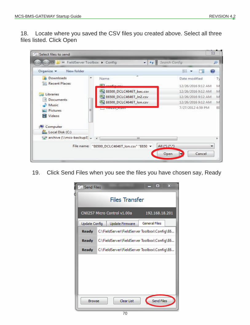
MCS-BMS-GATEWAY Startup Guide REVISION 4.2
70
18. Locate where you saved the CSV files you created above. Select all three files listed. Click Open
19. Click Send Files when you see the files you have chosen say, Ready

MCS-BMS-GATEWAY Startup Guide REVISION 4.2
71
20. Once all files are sent, close the file transfer box by clicking on the X at the top of the screen.
21. Once closed you should be brought back to the Configure Device window, you will need to click restart device. Once that is completed your device has been programmed and is ready for use.

MCS-BMS-GATEWAY Startup Guide REVISION 4.2
72
Chapter - 11. Reference and Specifications
*Customer ProtoCarrier Startup Guide
Page 37 of 38
Appendix D. Reference
Appendix D.1. Specifications
ProtoCarrier FPC-C35
Electrical Connections
One 6-pin Phoenix connector with: RS-485 port (+ / - / gnd) Power port (+ / - / Frame-gnd)
One 2-pin Phoenix connector with: One Ethernet 10/100 BaseT port One FTT-10 LonWorks port
Approvals
CE Certified; TUV approved to UL 916, EN 60950-1, EN 50491-3 and CSA C22-2 standards; FCC Class A Part 15; DNP3 Conformance Tested; RoHS Compliant; CSA 205 Approved BTL Marked LonMark Certified
Power Requirements Multi-mode power adapter: 9-30VDC or 12 - 24VAC Physical Dimensions 11.5 cm L x 8.3 cm W x 4.1 cm H (4.5 x 3.2 x 1.6 in.) Weight 0.2 kg (0.4 lbs) Operating Temperature -40°C to 75°C (-40°F to167°F) Surge Suppression EN61000-4-2 ESD EN61000-4-3 EMC EN61000-4-4 EFT Humidity 5 - 90% RH (non-condensing) (Specifications subject to change without notice)
Figure 23: Specifications
Appendix D.1.1. Compliance with UL Regulations
For UL compliance, the following instructions must be met when operating ProtoCarrier.
The units shall be powered by listed LPS or Class 2 power supply suited to the expected operating temperature range.
The interconnecting power connector and power cable shall: o Comply with local electrical code o Be suited to the expected operating temperature range o Meet the current and voltage rating for ProtoCarrier
Furthermore, the interconnecting power cable shall: o Be of length not exceeding 3.05m (118.3”) o Be constructed of materials rated VW-1, FT-1 or better
If the unit is to be installed in an operating environment with a temperature above 65 °C, it should be installed in a Restricted Access Area requiring a key or a special tool to gain access.
This device must not be connected to a LAN segment with outdoor wiring.
11.1. Compliance with UL Regulations• For UL compliance, the following instructions must be met when operating MCS-BMS-GATE-
WAY.• The units shall be powered by listed LPS or Class 2 power supply suited to the expected operating
temperature range.• The interconnecting power connector and power cable shall:
�� Comply with local electrical code�� Be suited to the expected operating temperature range�� Meet the current and voltage rating for MCS-BMS-GATEWAY
• Furthermore, the interconnecting power cable shall:�� Beoflengthnotexceeding3.05m(118.3”)�� Be constructed of materials rated VW-1, FT-1 or better
• If the unit is to be installed in an operating environment with a temperature above 65 °C, it should be installed in a Restricted Access Area requiring a key or a special tool to gain access.
• This device must not be connected to a LAN segment with outdoor wiring.

MCS-BMS-GATEWAY Startup Guide REVISION 4.2
73

Providing HVAC/R Control Solutions Worldwide
5580 Enterprise Pkwy. Fort Myers, FL 33905Office: (239) 694-0089Fax: (239) 694-0031
www.mcscontrols.com