Ver. 01 OPERATION MANUAL - strumedical.com CE manuale... · Appropriate drugs for treatment of...
110
STRESS TEST SOFTWARE FOR FX-7542 FP-1003 Ver. 01 OPERATION MANUAL 0086 Before using this device, read this operation manual. Store this manual in a safe location near the unit for future reference.
Transcript of Ver. 01 OPERATION MANUAL - strumedical.com CE manuale... · Appropriate drugs for treatment of...

STRESS TEST SOFTWARE
FOR FX-7542
FP-1003Ver. 01
OPERATION MANUAL
0086
� Before using this device, read this operation manual. � Store this manual in a safe location near the unit for future reference.

0086 This device bears a CE label in accordance with the provisions of Medical Device Directive 93/42/EEC. THE PERSONS RESPONSIBLE FOR PLACING DEVICES ON THE EC MARKET UNDER MDD 93/42/EEC. NAME: FUKUDA DENSHI UK ADDRESS: 13 WESTMINSTER COURT, HIPLEY STREET OLD WOKING, SURREY GU22 9LG, U.K. Copyright © 2007 by Fukuda Denshi Co., Ltd. No part of this document may be copied or transmitted in any form without the prior written permission of Fukuda Denshi Co., Ltd. Printed in Japan

1
IntroductionThank you for purchasing our stress test software.
This operation manual is a guide to proper operation of the stress test software (FP-1003) for CardiMax FX-7542.
Read the operation manual supplied with the FX-7542 first, and then read this manual carefully to understand the contents thoroughly before using the software. We recommend you to keep this operation manual near at hand while operating the equipment.
If you have any questions or opinions on the product or the manual, contact your local Fukuda Denshi sales or service representative.
This Operation Manual is for the FP-1003 Version 01.
2
Contents of This Manual This operation manual consists of the following six chapters.
Chapter 1 Regarding the stress test
This chapter describes the outline of the stress test and cautions in conducting the test.
Chapter 2 Conducting a stress test
This chapter describes how to conduct a stress test.
Chapter 3 Setting the stress test
This chapter describes the details of various settings on the stress test.
Chapter 4 Report
This chapter provides examples of recording of reports.
Chapter 5 Installation
This chapter describes how to install this optional software.
Chapter 6 Appendix
This chapter describes major specifications, optional items, error messages, etc.
Notation in This Manual ��Function keys are enclosed in square brackets [ ].
��[NOTE] provides information that is essential to use this software properly. Be sure to read the contents.
��[MEMO] provides detailed description of the operation and related information.
�� The arrow mark indicates the part that must be referred to.

3
Safety Precautions The following safety symbols are used throughout this manual. Each symbol has different meanings as shown below. Be sure to read the contents provided with these symbols to use the equipment safely and properly.
Warning display: Describes the degree of injuries and damages that may be caused by
handling the software improperly, ignoring the contents of the display. Consequences of improper handling are classified as follows.
DANGER Failure to follow these instructions could cause death, serious injury, or imminent danger of fire.
WARNING Failure to follow these instructions could cause death, serious injury, or fire.
NOTE A note provides information about the proper use and operating methods to prevent incorrect operations and trouble with the equipment.
Safety Icons Icon display: The following icons are used as part of warning display to describe
prohibited, mandatory, and other actions.
Provides instructions on how to cope with dangers, warnings, and cautions. Detailed instructions are provided next to the icon.
Indicates actions that must be performed.

4
[To Prevent accidents] The stress test, which is intended for those who have shown normal resting ECG analysis result, has been used to diagnose potential coronary diseases.
It has recently been used also for the assessment of those who have failed in resting ECG analysis as well as those who have been diagnosed as having cardiac dysfunction, judgment of treatment, and rehabilitations. Consequently the risk of occurrence of accidents during a stress test tends to increase.
To conduct a stress test safely, it is essential to take every possible measure to prevent an accident, and follow appropriate procedures immediately if one should occur.
WARNING
�� It is desirable that a stress test be conducted under no influence of medication. Unless the test is to be conducted to assess the effect of a treatment, medication should be discontinued several days to 1 week before the date of the test. If it is not possible, record the type of medication, dosage, administration time, and other necessary information.
� Conduct a stress test under the supervision of a physician and under conditions where appropriate measures can be taken immediately if abnormalities should occur.
� Pay particular attention to prevent accidents and maintain reproducibility of analysis result when conducting a stress test.
� Since postural hypotension, arrhythmia, and subjective symptoms may appear later during the recovery period of the stress test, keep monitoring the ECG for at least 6 minutes after the equipment is stopped to check that no abnormalities are occurring.
CAUTION
�� To maintain reproducibility of the test at a favorable level, it is desirable to prohibit the patient from eating, drinking, and smoking within 2 hours before the test.
� Create a stress test protocol for each patient beforehand according to his/her conditions and the purpose of the analysis. Do not increase stress arbitrarily. If a danger sign should appear, immediately stop the stress test.
�� It is desirable to obtain the patient’s consent prior to the test.

5
[Precautions for examiners] It is necessary for the supervisor of the stress test to check that the patient does not show any symptoms of acute cardiovascular system diseases or other clinical symptoms that may worsen as a result of doing hard exercise. Perform physical examination of the patient’s cardiovascular system to check that the system does not show any symptoms of acute alteration and that there are no orthopaedic or other exercise-impairing abnormalities.
The examiner should monitor the ECG at all times to find abrupt occurrence of arrhythmia without delay, thus taking necessary measures to prevent occurrence of an accident. If the patient’s blood pressure decreases, the possibility of occurrence of an accident may increase. It is therefore desirable that the blood pressure of a cardiac disease patient, coronary disease patient having the history of cardiac failure or 2 to 3 branch lesions in particular, be monitored during the stress test.
DANGER
�� Be sure to examine the medical history of the patient in detail before conducting a stress test, and check the status of a recent anginal attack in detail, if any. If the patient has a severe cardiac disease, cerebrovascular disease, neurological or muscle disease, or other diseases requiring complete rest, do not perform a stress test.
� Record resting ECG data before starting a stress test and determine whether the patient can take the test based on the record. If arrhythmia involving risks such as apparent Q waveform abnormality, ST increase/decrease, severe atrioventricular block, conduction disturbance, and frequent extrasystole is found, do not conduct a stress test as a rule.
CAUTION
�� Explain to the patient the risk of danger that may occur, instructing him/her to immediately inform you of his/her feeling of discomfort and other physical changes, if one should occur.
� Tell the patient that he/she should avoid taking a shower or bath for 30 minutes after the completion of the test because it may cause arrhythmia or other abnormal symptoms.
�� Explain the purpose and method of the test to the patient thoroughly to remove his/her sense of unease.
6
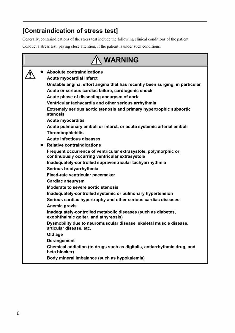
[Contraindication of stress test] Generally, contraindications of the stress test include the following clinical conditions of the patient.
Conduct a stress test, paying close attention, if the patient is under such conditions.
WARNING
�� Absolute contraindications Acute myocardial infarct Unstable angina, effort angina that has recently been surging, in particular Acute or serious cardiac failure, cardiogenic shock Acute phase of dissecting aneurysm of aorta Ventricular tachycardia and other serious arrhythmia Extremely serious aortic stenosis and primary hypertrophic subaortic stenosis Acute myocarditis Acute pulmonary emboli or infarct, or acute systemic arterial emboli Thrombophlebitis Acute infectious diseases
� Relative contraindications Frequent occurrence of ventricular extrasystole, polymorphic or continuously occurring ventricular extrasystole Inadequately-controlled supraventricular tachyarrhythmia Serious bradyarrhythmia Fixed-rate ventricular pacemaker Cardiac aneurysm Moderate to severe aortic stenosis Inadequately-controlled systemic or pulmonary hypertension Serious cardiac hypertrophy and other serious cardiac diseases Anemia gravis Inadequately-controlled metabolic diseases (such as diabetes, exophthalmic goiter, and athyreosis) Dysmobility due to neuromuscular disease, skeletal muscle disease, articular disease, etc. Old age Derangement Chemical addiction (to drugs such as digitalis, antiarrhythmic drug, and beta blocker) Body mineral imbalance (such as hypokalemia)

7
[Signs indicating that the stress test should be discontinued] The following signs of the patient are generally considered to necessitate discontinuance of the stress test.
If one of these signs appears, decrease the exercise level or immediately discontinue the test.
DANGER
�� Subjective signs Chest pain, gradually worsening chest pain in particular [*], serious dyspnea (excluding minor and extracardiac dyspnea) [*], vertgo [*], abnormal vision [*] Extreme fatigue [*] Pain due to leg muscle ischemia
� Objective signs Signs of cerebral ischemia [*] (such as ataxia and poor response to questions or instructions) Signs of peripheral circulatory failure [*] (such as paleness, cyanosis, cold sweats) Significant ECG abnormality that is not observed when the patient is at rest
(a) Progressive ST segment depression (>0.3 mV) or elevation (>0.2 mV) (b) Increase of occurrence of ventricular extrasystole (once in every 5
heart beats or more), occurrence of polymorphic, R-on-T, or 3 or more consecutive ventricular extrasystole
(c) Occurrence and continuance of atrial tachyarrhythmia (d) Occurrence of atrioventricular block, left bundle-branch block, and
other intraventricular conduction disturbance Decrease of systolic blood pressure (10 mmHg or more against the peak value) or heart rate observed despite the increase of exercise intensity Abnormal elevation of blood pressure (systolic pressure � 260 mmHg or diastolic pressure � 120 mmHg) In the near-maximal stress method [*], let the patient stop exercising when the target heart rate [**] is reached. [*]: Signs for absolute discontinuance of exercise [**]: 85 to 90% of the maximum heart rate predicted by age in general

8
[First-aid tools and drugs that should be provided in the stress test chamber] To conduct a stress test safely, it is essential to take every possible measure to prevent an accident, and follow appropriate procedures immediately if one should occur.
CAUTION
�� If an accident should occur, follow appropriate procedures immediately. Maintain the following first-aid tools in the stress test chamber to quickly cope with an accident. Defibrillator (Synchronous DC defibrillator is desirable.) Intermittent oxygen breathing apparatus Airway for oral cavity and windpipe, bag valve mask, manual respiratory apparatus Injection syringes and needles Intravenous injection set and stand Adhesive tape Laryngoscope Stethoscope Hemodynamometer Cutdown set (sterilized) Appropriate drugs for treatment of cardiac standstill, myocardial infarct, serious arrhythmia, and deliquium

9
How to Read This Manual This manual uses the following symbols to demonstrate the degree of importance of information. This marks indicate the
following. [NOTE]: Provides information
required to use the equipment properly. Be sure to read the contents.
[MEMO]: Provides detailed explanation on operation and related information.
The following icons indicate the order of pressing the screen.
Indicates the operating procedure. Follow the instructions provided here. ��The function keys displayed on the
screen are enclosed in square brackets [ ]. Example: [AUTO], [MENU]
��The keys on the operation panel are enclosed in rectangles . Example: ,
Supplementary explanations on operating procedure Provides detailed procedure and supplementary information on operation.

10
11
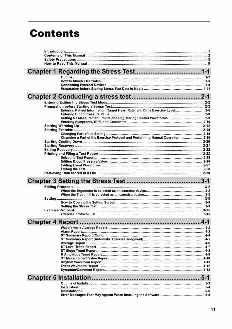
Contents
Introduction................................................................................................................................................. 1 Contents of This Manual ............................................................................................................................ 2 Safety Precautions ..................................................................................................................................... 3 How to Read This Manual .......................................................................................................................... 9
Chapter 1 Regarding the Stress Test......................................1-1 Outline ................................................................................................................................................ 1-2 How to Attach Electrodes ................................................................................................................. 1-3 Connecting External Devices........................................................................................................... 1-8 Preparation before Storing Stress Test Data in Media .................................................................1-11
Chapter 2 Conducting a stress test........................................2-1 Entering/Exiting the Stress Test Mode................................................................................................... 2-2 Preparation before Starting a Stress Test.............................................................................................. 2-3
Entering Patient Information, Target Heart Rate, and Daily Exercise Level................................ 2-6 Entering Blood Pressure Value........................................................................................................ 2-8 Setting ST Measurement Points and Registering Control Waveforms........................................ 2-9 Entering Symptoms, RPE, and Comments................................................................................... 2-10
Starting Warming Up ............................................................................................................................. 2-12 Starting Exercise ................................................................................................................................... 2-14
Changing Part of the Setting.......................................................................................................... 2-18 Changing a Part of the Exercise Protocol and Performing Manual Operation......................... 2-19
Starting Cooling Down .......................................................................................................................... 2-20 Starting Recovery .................................................................................................................................. 2-21 Exiting Recovery.................................................................................................................................... 2-22 Printing and Filing a Test Report.......................................................................................................... 2-23
Selecting Test Report...................................................................................................................... 2-25 Editing Blood Pressure Value ........................................................................................................ 2-26 Editing Event Waveforms ............................................................................................................... 2-27 Exiting the Test ................................................................................................................................ 2-28
Retrieving Data Stored in a File............................................................................................................ 2-29
Chapter 3 Setting the Stress Test ...........................................3-1 Editing Protocols ..................................................................................................................................... 3-2
When the Ergometer is selected as an exercise device................................................................ 3-2 When the Treadmill is selected as an exercise device.................................................................. 3-5
Setting ...................................................................................................................................................... 3-8 How to Operate the Setting Screen ................................................................................................. 3-8 Setting the Stress Test...................................................................................................................... 3-9
Exercise Protocol .................................................................................................................................. 3-15 Exercise protocol List ..................................................................................................................... 3-15
Chapter 4 Report ......................................................................4-1 Waveforms + Average Report .......................................................................................................... 4-2 Alarm Report...................................................................................................................................... 4-3 ST Summary Report (Option)........................................................................................................... 4-4 ST Summary Report (Automatic Exercise Judgment) .................................................................. 4-5 Average Report .................................................................................................................................. 4-6 ST Level Trend Report ...................................................................................................................... 4-7 ST Slope Trend Report...................................................................................................................... 4-8 R Amplitude Trend Report ................................................................................................................ 4-9 ST Measurement Value Report....................................................................................................... 4-10 Rhythm Waveform Report ...............................................................................................................4-11 Event Waveform Report.................................................................................................................. 4-12 Symptom/Comment Report............................................................................................................ 4-13
Chapter 5 Installation ...............................................................5-1 Outline of Installation........................................................................................................................ 5-3 Installation.......................................................................................................................................... 5-4 Uninstallation..................................................................................................................................... 5-6 Error Messages That May Appear When Installing the Software ................................................. 5-8

12
Chapter 6 Appendix................................................................. 6-1 Major Specifications.......................................................................................................................... 6-2 Accessories........................................................................................................................................ 6-3 Optional Items.................................................................................................................................... 6-4 Alarms and Error Messages............................................................................................................. 6-7

Chapter 1 Regarding the Stress Test
A stress test is an ECG analysis performed using an exercise device such as an ergometer or treadmill.
Outline .......................................................................................1-2 How to Attach Electrodes ......................................................1-3 Connecting External Devices ...............................................1-8 Preparation before Storing Stress Test Data in Media ...1-11

1-2
Outline
A stress test is an ECG analysis performed using an exercise device such as an ergometer and treadmill.
Prescriptions for ergotherapy can be printed based on the result of the stress test conducted.
The stress test can be conducted under the following 4 conditions: Before the start of exercise (state at rest including warming up), during exercise, during recovery (including cooling down), and after exercise.
The following table provides details of the test under the 4 conditions.
Condition Description Before exercise (At rest)
• ECG recording is made while the patient is at rest. • Various setting can be made.
During exercise
• The exercise device and NIBP monitor are controlled. • ST measurement and detection of arrhythmia are performed based on average
waveforms. • ECG recording (arbitrary, fixed-time, and alarm) is made during exercise. • The change of ST level can be checked on the screen.
During recovery
• The NIBP monitor is controlled. • ST measurement and detection of arrhythmia are performed based on average
waveforms. • ECG recording (arbitrary, fixed-time, and alarm) is made during recovery. • The change of ST level can be checked on the screen.
After exercise
• The result of the stress test is recorded as a report. • Prescriptions for ergotherapy are printed. • Events and blood pressure values are edited. • The analysis results are filed.
The basic flow of the test is shown below.
[MEMO] Use an exercise device such as an ergometer or treadmill for the stress test. See “Chapter 6 Appendix, Optional Items” on page 6-4 for the connectable external devices.
[Starts exercise] [Starts recovery] [Ends recovery] [Returns to resting]
Before exercise (including WU)
Exercise Recovery (including CD) After exercise
[Start/Stop]
Resting ECG
Set time
Fixed-time recording
Set time
Fixed-time recording
Test report

Chapter 1 Regarding the Stress Test
1-3
How to Attach Electrodes
Electrodes and patient cables for the stress test are not supplied as standard. Contact us if you need them.
ON OFF
BATTERY CHECK
CIS-03BKPE
1 Press the battery check button of the INPUT BOX CIS-03BKPE/CIS-03BKPA (optional). Check that the LED comes on in green.
If the LED comes on in orange or does not come on, replace the batteries.
[NOTE] Insert batteries according to the orientation shown on the battery box, paying attention not to reverse the polarity.
[NOTE] Replace all the 4 batteries, paying attention to the polarity.
[NOTE] The service life of the battery is 20 days or longer (when used continuously under 20°C environment).
2 Insert the cord for electrode lead into the connector of the input box.
3 Select a desired electrode position. Select either 12-lead (page 1-6) or bipolar chest lead (page 1-7) position.
Remaining battery level check LED (Green/ Orange)
Power switch
Battery lid
Belt loop
Battery check button
Lead insertion slot Connector

1-4
4 Prepare the patient’s skin. Apply skin cleaner to remove excess oil at electrode attachment positions until the areas turn slightly reddish.
Then wipe the skin cleaner off completely with tissues.
[NOTE] Use gauze soaked in alcohol instead of skin cleaner for patients with sensitive or irritated skin.
[NOTE] Shave chest hair if it is too thick.
5 Stretch the patient’s skin and attach clip electrode.
6 Connect the terminal area of the cord for electrode lead to the clip electrode.
7 Turn the contact area (electrode lead) and check the connection status.
8 Fasten the electrode lead by covering it with adhesive tape. Keep the cord slightly loose to prevent direct force from being applied to the electrode.
Adhesive tape

Chapter 1 Regarding the Stress Test
1-5
When attaching electrodes to the patient who tends to perspire a lot, cover them with adhesive tape to prevent them from peeling off his/her skin during exercise.
[NOTE] When attaching electrodes to a female or fat patient or to a patient whose skin tends to sag, fasten them with an elastic belt to prevent them from moving while the patient is doing exercise. Be careful not to fasten them too tight to prevent occurrence of electromyogram.
[NOTE] Do not let the patient wear his/her clothes once the electrodes are attached unless it is inevitable. Otherwise the electrodes and clothes may rub against each other during exercise, thus causing unstable ECG recording.
[MEMO] Use optional Echo Drape M (OA-430M) instead of adhesive tape to prevent the electrodes from peeling off easily.
9 When all the electrodes are attached to their specified positions, fasten the cords with adhesive tape. Insert the sagging part of the cords for the electrode leads into the gap between the belt and the patient’s skin, or attach the cables to his/her skin with adhesive tape to prevent them from swaying as far as possible.
10 Set the power switch to the “ON” position.
[MEMO] Remember to set the power switch back to “OFF” when the test is completed.
11 Check that waveforms are displayed properly and are stable and that none of the electrodes have come off.
Echo Drape
Electrode
Lead
Skin surface
Adhesive tape
1-6
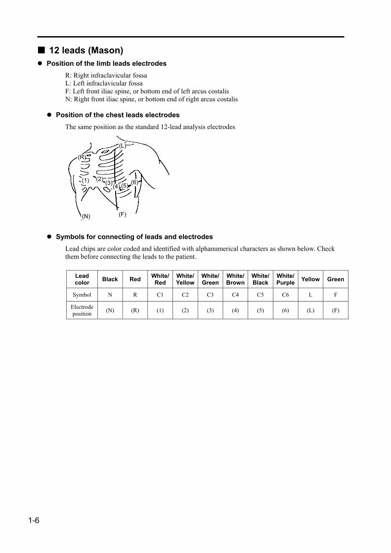
��12 leads (Mason) � Position of the limb leads electrodes
R: Right infraclavicular fossa L: Left infraclavicular fossa F: Left front iliac spine, or bottom end of left arcus costalis N: Right front iliac spine, or bottom end of right arcus costalis
� Position of the chest leads electrodes The same position as the standard 12-lead analysis electrodes
� Symbols for connecting of leads and electrodes Lead chips are color coded and identified with alphanumerical characters as shown below. Check them before connecting the leads to the patient.
Lead color Black Red White/
Red White/Yellow
White/Green
White/Brown
White/Black
White/Purple Yellow Green
Symbol N R C1 C2 C3 C4 C5 C6 L F
Electrode position (N) (R) (1) (2) (3) (4) (5) (6) (L) (F)
(1) (2) (3) (4) (5) (6)
(R)
(L)
(N) (F)

Chapter 1 Regarding the Stress Test
1-7
��Bipolar chest lead
� Electrode position of CM5 lead 5: Fifth costa on the left anterior axillary line M: Episternum at the upper end of chest N: On the first costa in right chest
� Electrode position of CC5 lead 5: Fifth costa on the left anterior axillary line 5R: Fifth costa on the right anterior axillary line N: On the first costa in right chest
� Electrode position of CL lead F: Left front iliac spine, or bottom end of left arcus costalis M: Episternum at the upper end of chest N: On the first costa in right chest
� Symbols for connecting of leads and electrodes Lead chips are color coded and identified with alphanumerical characters as shown below. Check them before connecting the leads to the patient.
Lead color Black Red White/
Red White/Yellow
White/Green
White/Brown
White/Black
White/Purple Yellow Green
Symbol N R C1 C2 C3 C4 C5 C6 L F
Electrode position (N) � (5R) (M) � � (5) � � (F)
(5R) (5)
(N) (M)
(F)

1-8
Connecting External Devices
��Connecting an ergometer Connect the ergometer (optional) to the serial port of the main unit.
WARNING
��Contact us when connecting external devices to the main unit. The patient and the operator may be exposed to the risk of an electric shock and other dangerous situations.
[NOTE] The cable used to connect the main unit and the optional devices varies depending on the type of the optional device. Improper connection may result in failure. Be sure to contact us when connecting external devices.
[NOTE] Only one ergometer can be connected at a time.
��Insert the optional connecting cable into the serial port of the main unit.
��You can insert it into any one of the three serial ports provided.
��On “Serial port” of the stress test setting, select the port to which the ergometer is connected.
ergoline
[NOTE] When connecting external devices to the FX-7542, use a cable with a clamp filter. To decrease unwanted radio emission, use cables with a clamp filter when connecting various external devices to the equipment. The specified cable with a clamp filter is marked with “core attached” after the cable type.
Ergometer
FX-7542
Connecting cable (option)
Connect to serial port.

Chapter 1 Regarding the Stress Test
1-9
��Connecting a treadmill Connect the treadmill (optional) to the serial port of the main unit.
WARNING
��Contact us when connecting external devices to the main unit. The patient and the operator may be exposed to the risk of an electric shock and other dangerous situations.
[NOTE] The cable used to connect the main unit and the optional devices varies depending on the type of the optional device. Improper connection may result in failure. Be sure to contact us when connecting external device.
[NOTE] Only one treadmill can be connected at a time.
��Insert the optional connecting cable into the serial port of the main unit.
��You can insert it into any one of the three serial ports provided.
��On “Serial port” of the stress test setting, select the port to which the treadmill is connected.
Mad 770 CE
RAM
[NOTE] When connecting external devices to the FX-7542, use a cable with a clamp filter. To decrease unwanted radio emission, use cables installed with a clamp filter when connecting various external devices to the equipment. The specified cable with a clamp filter is marked with “core attached” after the cable type.
Treadmill
FX-7542
Connecting cable (option)
Connect to serial port.
1-10
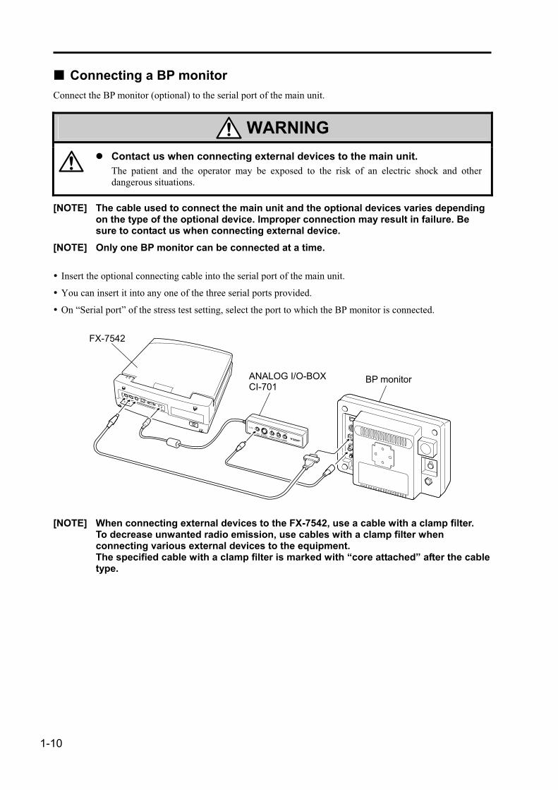
��Connecting a BP monitor Connect the BP monitor (optional) to the serial port of the main unit.
WARNING
��Contact us when connecting external devices to the main unit. The patient and the operator may be exposed to the risk of an electric shock and other dangerous situations.
[NOTE] The cable used to connect the main unit and the optional devices varies depending on the type of the optional device. Improper connection may result in failure. Be sure to contact us when connecting external device.
[NOTE] Only one BP monitor can be connected at a time.
��Insert the optional connecting cable into the serial port of the main unit.
��You can insert it into any one of the three serial ports provided.
��On “Serial port” of the stress test setting, select the port to which the BP monitor is connected.
ECG OUT
R-SYC
CI-7013
21
SIGNAL IN
[NOTE] When connecting external devices to the FX-7542, use a cable with a clamp filter. To decrease unwanted radio emission, use cables with a clamp filter when connecting various external devices to the equipment. The specified cable with a clamp filter is marked with “core attached” after the cable type.
BP monitor ANALOG I/O-BOXCI-701
FX-7542

Chapter 1 Regarding the Stress Test
1-11
Preparation before Storing Stress Test Data in Media
The data obtained through a stress test can be stored in a PC card, CF card, or DMS.
When storing the data in each medium, check that the medium has sufficient capacity to store the data before conducting a stress test.
The following table lists the capacity of a PC card, “FMC-20” and CF card, “FCF-64.”
Data type Condition Number of storable data
FMC-20 FCF-64
Stress test data Test time: 30 min. Approximately 50 files Approximately 150 files
[MEMO] The number of files may vary depending on test conditions such as waveform quality.
A PC card or CF card that has just been purchased should be formatted before use. The stress test data cannot be stored in the medium unless it is formatted.

1-12

Chapter 2 Conducting a stress test
Conduct a stress test, following the instructions in this chapter. Be sure to make necessary settings on the stress test beforehand.
Entering/Exiting the Stress Test Mode .......................... 2-2
Preparation before Starting a Stress Test ..................... 2-3 Entering Patient Information, Target Heart Rate, and Daily
Exercise Level ....................................................................2-6 Entering Blood Pressure Value ............................................2-8 Setting ST Measurement Points and Registering Control
Waveforms..........................................................................2-9 Entering Symptoms, RPE, and Comments......................2-10
Starting Warming Up.......................................................2-12
Starting Exercise.............................................................. 2-14 Changing Part of the Setting...............................................2-18 Changing a Part of the Exercise Protocol and Performing
Manual Operation ............................................................2-19
Starting Cooling Down.................................................... 2-20
Starting Recovery............................................................ 2-21
Exiting Recovery.............................................................. 2-22
Printing and Filing a Test Report .................................. 2-23 Selecting Test Report ...........................................................2-25 Editing Blood Pressure Value.............................................2-26 Editing Event Waveforms....................................................2-27 Exiting the Test ......................................................................2-28
Retrieving Data Stored in a File..................................... 2-29
2-2
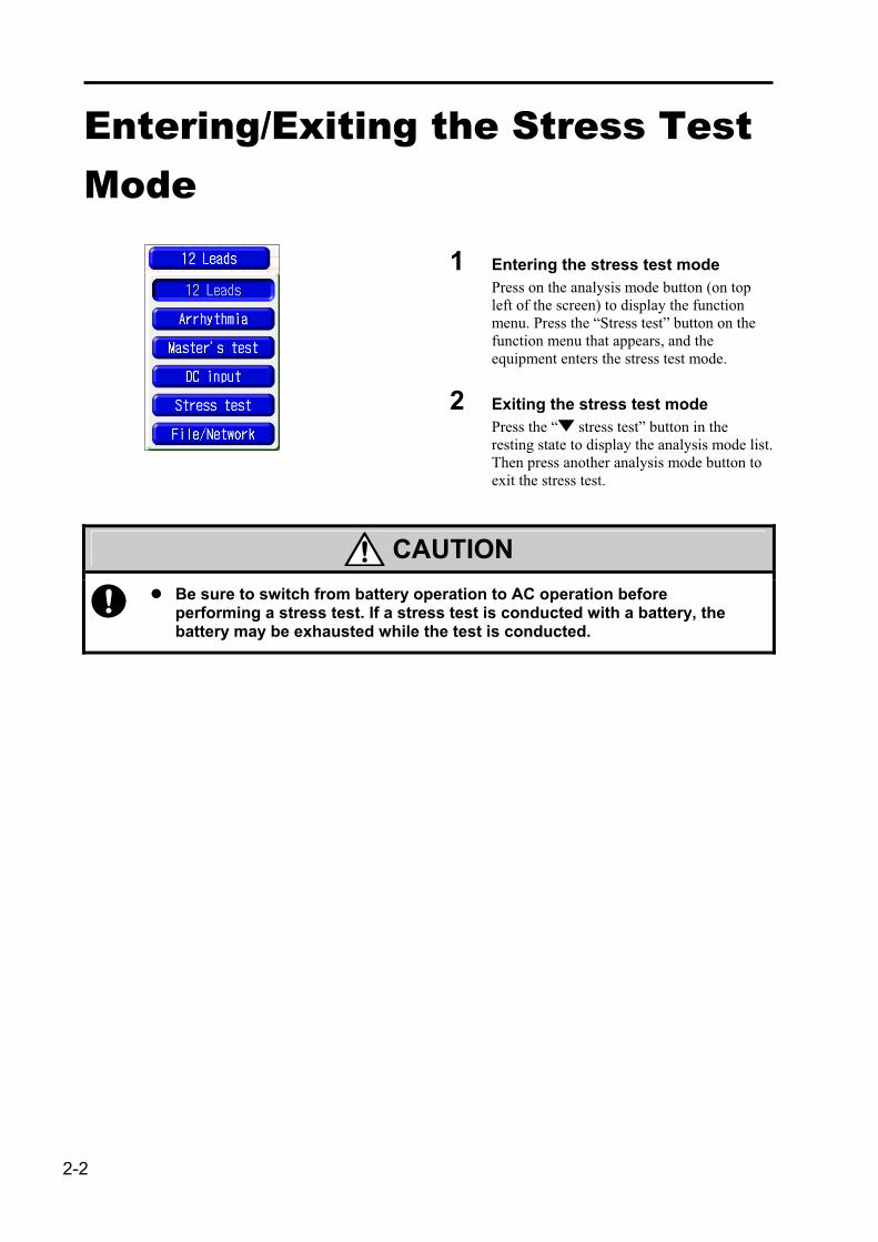
Entering/Exiting the Stress Test Mode
1 Entering the stress test mode Press on the analysis mode button (on top left of the screen) to display the function menu. Press the “Stress test” button on the function menu that appears, and the equipment enters the stress test mode.
2 Exiting the stress test mode Press the “ stress test” button in the resting state to display the analysis mode list. Then press another analysis mode button to exit the stress test.
CAUTION
��Be sure to switch from battery operation to AC operation before performing a stress test. If a stress test is conducted with a battery, the battery may be exhausted while the test is conducted.
Chapter 2 Conducting a stress test
2-3
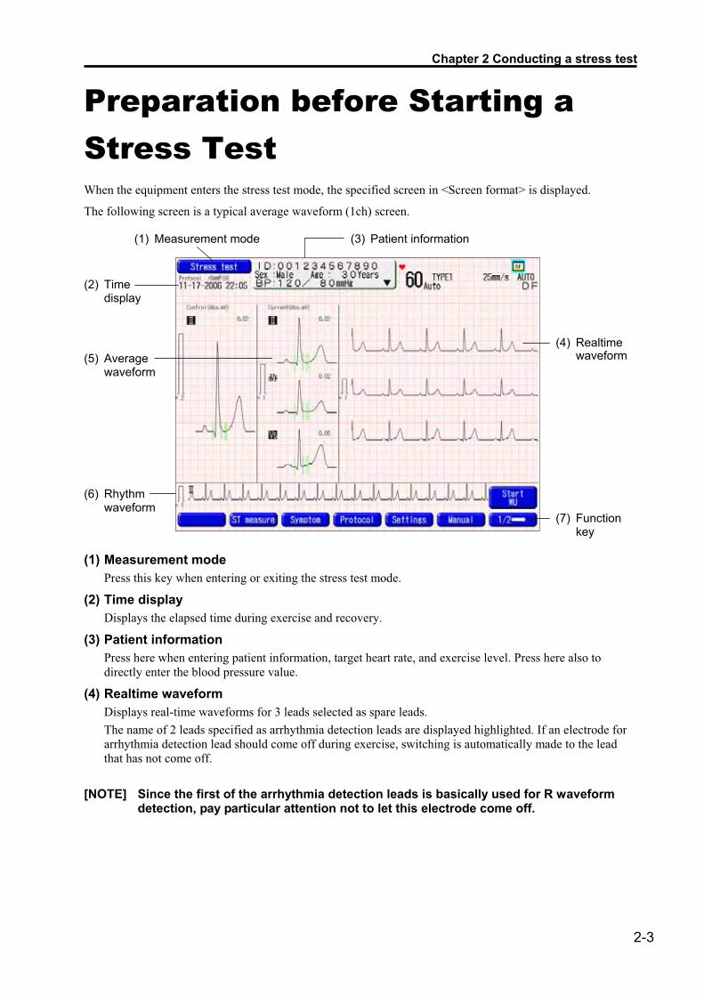
Preparation before Starting a Stress Test When the equipment enters the stress test mode, the specified screen in <Screen format> is displayed.
The following screen is a typical average waveform (1ch) screen.
(1) Measurement mode (3) Patient information
(2) Time
display (5) Average
waveform
(6) Rhythm waveform
(4) Realtime
waveform (7) Function
key
(1) Measurement mode Press this key when entering or exiting the stress test mode.
(2) Time display Displays the elapsed time during exercise and recovery.
(3) Patient information Press here when entering patient information, target heart rate, and exercise level. Press here also to directly enter the blood pressure value.
(4) Realtime waveform Displays real-time waveforms for 3 leads selected as spare leads. The name of 2 leads specified as arrhythmia detection leads are displayed highlighted. If an electrode for arrhythmia detection lead should come off during exercise, switching is automatically made to the lead that has not come off.
[NOTE] Since the first of the arrhythmia detection leads is basically used for R waveform detection, pay particular attention not to let this electrode come off.

2-4
(5) Average waveform Displays the average waveforms of one of the 3 leads selected as spare leads enlarged. Also displays the ST level. The name of the lead highlighted is used for R waveform detection or arrhythmia measurement. The control waveforms and current waveforms are displayed overlapped during exercise or recovery to clarify ST change.
(6) Rhythm waveform Displays the waveform for 1 lead specified as R waveform detection lead at 10 mm/s.
See “Printing and Filing a Test Report” on page 2-23.
(7) Function key Displays the functions that can be used in the stress test.
(Automatic recording mode)
Operation procedures are described below.
1 Press [Manual (Auto)] to specify a desired recording mode. Specify automatic or manual recording mode.
2 Press [Settings] to change the settings on the stress test. See “Setting” on page 3-8.
[NOTE] Select a desired media to which the analysis data is to be stored before starting the exercise. You cannot change the media after the test is completed.
3 Press [Protocol] to edit the protocol to be implemented. See “Editing Protocols” on page 3-2.
4 Press [Symptom] to enter the symptoms of the patient and your comments. See “Entering Symptoms, RPE, and Comments” on page 2-10.
5 Press [ST measure] to change ST measurement points and register control waveforms.
See “Setting ST Measurement Points and Registering Control Waveforms” on page 2-9.
6 Press [Filter] to select a desired filter. The default filter is “Filter setting 2” in the setting. The contents set by pressing the [Filter] function key are only temporary and are valid only until the stress test mode is exited.
See the operation manual supplied with the main unit for the filter setting.
7 Press [Screen] to select the screen format to be displayed. Select one from the screen formats registered in <Screen format> of the setting. See “Setting” on page 3-8.

Chapter 2 Conducting a stress test
2-5
8 [Menu], [Freeze], , , , , , , ,
See the operation manual supplied with the main unit for the operation procedures of these keys.
9 Press in the patient information area, and enter the patient information, target heart rate, and daily exercise level.
See “Entering Patient Information, Target Heart Rate, and Daily Exercise” on page 2-6.
10 Enter blood pressure. See “Entering Blood Pressure Value” on page 2-8.
11 Attach electrodes. Attach the electrodes properly.
See “How to Attach Electrodes” on page 1-3.
12 Record the resting ECG. Press to print the resting ECG on the recording paper.
13 Press [Start WU] or [Start exercise] to start the exercise. If warming up (WU) has been selected for exercise protocol, [Start WU] will be displayed.
See “Starting Warming Up” on page 2-12. See “Starting Exercise” on page 2-14.
[NOTE] If the electrode for the arrhythmia detection lead comes off, exercise cannot be started.

2-6
Entering Patient Information, Target Heart Rate, and Daily Exercise Level
1 Enter patient information, target heart rate, etc. Enter the patient information such as the name, age, and sex.
See the operation manual of the main unit for the method of entering patient information.
2 Press [HR] to enter the target heart rate. The target heart rate is automatically calculated if the patient’s age is entered according to the setting <Target heart rate calculation method>. If it is to be set arbitrarily, press [HR] and directly enter a desired value, or change the coefficient used for calculating the target heart rate in steps of ±5%.
� Blackburn method Maximum heart rate: 220 - Age Target heart rate:
Maximum heart rate × Coefficient (Coefficient: Default; 85%)
� Karvonen method Maximum heart rate: 220 - Age Target heart rate: (Maximum heart rate - Heart
rate at rest) × Coefficient + Heart rate at rest (Coefficient: Default; 70%)
Chapter 2 Conducting a stress test
2-7
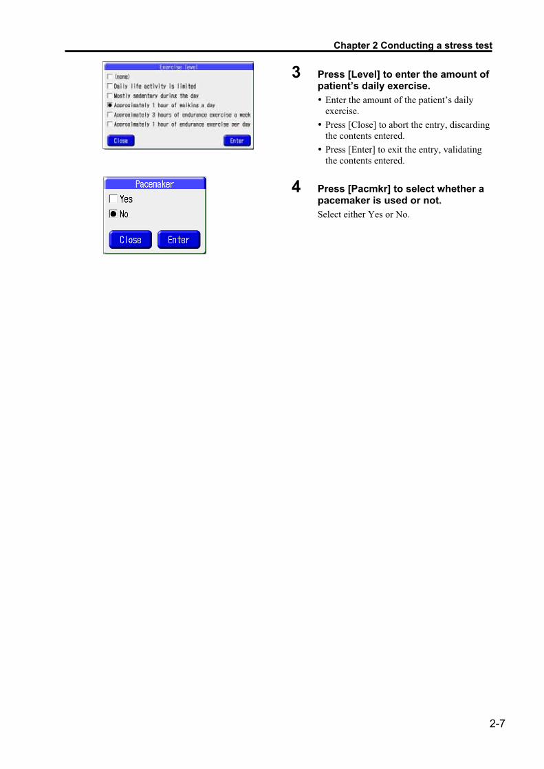
3 Press [Level] to enter the amount of patient’s daily exercise. ��Enter the amount of the patient’s daily
exercise. ��Press [Close] to abort the entry, discarding
the contents entered. ��Press [Enter] to exit the entry, validating
the contents entered.
4 Press [Pacmkr] to select whether a pacemaker is used or not. Select either Yes or No.

2-8
Entering Blood Pressure Value
1 At rest
The blood pressure value is displayed in the patient information window or the exercise data window.
Enter the value following the procedures shown below.
1 Press [BP] in the patient information window, and enter the blood pressure.
2 When measuring blood pressure with an automatic BP monitor Press [BP] in the function menu.
2 During exercise and recovery
1 When setting has been made to automatically measure blood pressure with an automatic BP monitor Blood pressure measurement is automatically started when the time specified by the protocol is reached.
Function menu
2 When measuring blood pressure manually with an automatic BP monitor Press [BP] in the function menu.
3 When an automatic BP monitor is not connected Press the button in the patient information window, and directly enter the value in the pressure entry window.
See the operation manual supplied with the main unit.
4 Changing blood pressure value The entered blood pressure value can be edited (changed) after the test is completed.
See “Editing Blood Pressure Value” on page 2-26.
[NOTE] To display [BP] in the function menu, specify the serial port to which the BP monitor is to be connected.
See “Setting, General” on page 3-9.

Chapter 2 Conducting a stress test
2-9
Setting ST Measurement Points and Registering Control Waveforms
Press [ST measure] in the function menu, and the control ST waveform at rest is displayed. The control ST waveform is used to check the relative ST change of the average waveforms during exercise.
The first lead of the set “arrhythmia detection leads” is displayed as the control waveform.
1 Change the control ST waveform. Press [Change control wave] to reregister the control ST waveform displayed. If registration has not been made, the average waveform at the start of the exercise is automatically registered as the control ST waveform.
2 Change the ST measurement point. To change the ST measurement points, follow the procedures shown below, referring to the position of the cursor on the control waveform. ��Select a desired ST measurement point from the following. The measurement point moves once every
4 ms. [ST referen]: Specify the reference point of the ST measurement before the R waveform in the range
from 20 to 200 ms. [STj]: Specify the STj point after the R waveform in the range from 20 to 200 ms. [ST level]: Specify the ST level measurement point after STj point within the range from 0 to 280
ms. [ST slope]: Specify the ST slope measurement point after STj point within the range from 40 to
280 ms. ��After selecting the measurement point, move the measurement point using the following keys.
[<<20ms]: Moves the point backward by 20 ms. [<4ms]: Moves the point backward by 4 ms. [4ms>]: Moves the point forward by 4 ms. [20ms>>]: Moves the point forward by 20 ms. [Cancel]: Restores the state before the change.
3 Restore the function setting of the ST measurement point. Press [Reset] to restore the default function setting.
4 Exit the ST measurement point setting and control ST waveform registration. Press [Close] to exit the change. (The set contents are made valid.)

2-10
Entering Symptoms, RPE, and Comments
Press [Symptom] to display the symptom window, on which you can enter the state of the patient such as RPE, symptoms (3 types), and your comments.
[Close]: Close the symptom window.
[Clear]: Deletes all the contents entered.
[MEMO] The contents entered are printed as “Symptom/comment” report on completion of the test.
See “Printing and Filing a Test Report” on page 2-23.
1 Enter RPE. Press [RPE], and select the intensity of exercise viewed from the patient from [(none)] and [7] to [20].
��Press [Close] to abort the entry, discarding
the contents entered. ��Press [Enter] to exit the entry, validating
the contents entered.
[MEMO] The RPE is the intensity of the exercise viewed subjectively by the patient (reaction of mind) expressed in 15 stages.
Chapter 2 Conducting a stress test
2-11
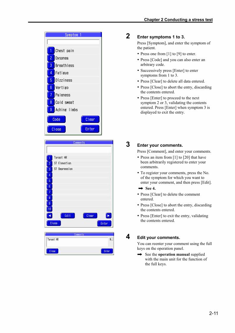
2 Enter symptoms 1 to 3. Press [Symptom], and enter the symptom of the patient. ��Press one from [1] to [9] to enter. ��Press [Code] and you can also enter an
arbitrary code. ��Successively press [Enter] to enter
symptoms from 1 to 3. ��Press [Clear] to delete all data entered. ��Press [Close] to abort the entry, discarding
the contents entered. ��Press [Enter] to proceed to the next
symptom 2 or 3, validating the contents entered. Press [Enter] when symptom 3 is displayed to exit the entry.
3 Enter your comments. Press [Comment], and enter your comments.��Press an item from [1] to [20] that have
been arbitrarily registered to enter your comments.
��To register your comments, press the No. of the symptom for which you want to enter your comment, and then press [Edit].
See 4. ��Press [Clear] to delete the comment
entered. ��Press [Close] to abort the entry, discarding
the contents entered. ��Press [Enter] to exit the entry, validating
the contents entered.
4 Edit your comments. You can reenter your comment using the full keys on the operation panel.
See the operation manual supplied with the main unit for the function of the full keys.

2-12
Starting Warming Up If warm-up (WU) time has been set in the exercise protocol, the test will start, beginning from WU.
Press [Start WU], and the operation will start, following the exercise protocol set beforehand.
When WU is completed, the equipment proceeds to [Exer], where exercise stage control, periodic recording, blood pressure measurement, etc. are performed according to the selected protocol.
The following screen remains displayed while the WU is performed.
See “Setting, Display” on page 3-11.
� Function key
(Automatic recording mode)

Chapter 2 Conducting a stress test
2-13
The operation during WU is as follows.
1 Enter blood pressure. See “Entering Blood Pressure Value” on page 2-8.
2 Press [Event] to register the waveform at that time as an event waveform. The waveform from the first lead specified as the arrhythmia detection lead can be printed for 10 seconds after the stress test is completed.
See “Editing Event Waveforms” on page 2-27. See “Chapter 4 Report, Event Waveform Report” on page 4-12.
3 Press [Symptom] to and enter the state of the patient such as RPE and your comments.
See “Entering Symptoms, RPE, and Comments” on page 2-10. See “Chapter 4 Report, Symptom/Comment Report” on page 4-13.
4 Press [Screen] to select a screen format to be displayed. Select a screen format from those registered in <Screen format> of the setting.
See “Setting, Display” on page 3-11.
5 Press [Selections] to select whether to continue or stop performing each function. In simple setting, change of screens or recording as well as temporary reset of the events such as stop load, memory storage, alarm recording, and alarm sound can be made.
See “Changing Part of the Setting” on page 2-18.
6 Exit WU and proceed to exercise. When WU is completed or [Start exercise] is pressed, WU is terminated and the exercise is started.
See “Starting Exercise” on page 2-14.
7 Press [Stop exer] to return to the resting state, stopping the exercise.
2-14
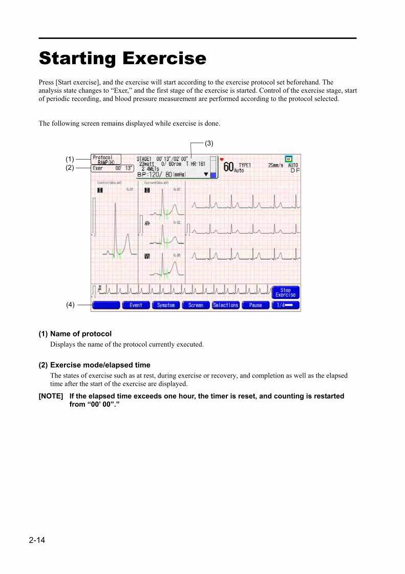
Starting Exercise Press [Start exercise], and the exercise will start according to the exercise protocol set beforehand. The analysis state changes to “Exer,” and the first stage of the exercise is started. Control of the exercise stage, start of periodic recording, and blood pressure measurement are performed according to the protocol selected.
The following screen remains displayed while exercise is done.
(3)
(1) (2)
(4)
(1) Name of protocol Displays the name of the protocol currently executed.
(2) Exercise mode/elapsed time The states of exercise such as at rest, during exercise or recovery, and completion as well as the elapsed time after the start of the exercise are displayed.
[NOTE] If the elapsed time exceeds one hour, the timer is reset, and counting is restarted from “00’ 00”.”

Chapter 2 Conducting a stress test
2-15
(3) Exercise data
� When an ergometer is selected as an exercise device
a b g
c d
e f
a: Stage name
b: Stage elapsed time/set time
c: Wattage (watt), current rpm/set rpm
d: Mets See “Chapter 6 Appendix, Major Specifications” on page 6-2.
e: Blood pressure value display
f: Blood pressure entry button
g: Target heart rate, maximum heart rate reach rate graph
� When a treadmill is selected as an exercise device.
a b g
c d
e f
a: Stage name
b: Stage elapsed time/set time
c: Speed (km/h) or (Mile/h), gradient (%)
d: Mets See “Chapter 6 Appendix, Major Specifications” on page 6-2.
e: Blood pressure value display
f: Blood pressure entry button
g: Target heart rate, maximum heart rate reach rate graph

2-16
(4) Function key
� When an ergometer is selected as an exercise device
(Automatic recording mode)
� When a treadmill is selected as an exercise device
(Automatic recording mode)
The operation during exercise is described below.
1 Enter blood pressure value. See “Entering Blood Pressure Value” on page 2-8.
2 Press [Event] to register the waveform at that time as an event waveform. The waveform from the first lead specified as the arrhythmia detection lead can be printed for 10 seconds after the stress test is completed.
See “Editing Event Waveforms” on page 2-27. See “Chapter 4 Report, Event Waveform Report” on page 4-12.
3 Press [Symptom] to enter the state of the patient such as RPE and your comments. See “Entering Symptoms, RPE, and Comments” on page 2-10. See “Chapter 4 Report, Symptom/Comment Report” on page 4-13.
4 Press [Screen] to select a screen format to be displayed. Select a screen format from those registered in <Screen format> of the setting.
See “Setting, Display” on page 3-11.

Chapter 2 Conducting a stress test
2-17
5 Press [Selections] to select whether to continue or stop performing each function. In brief setting, change of screens or recording as well as temporary reset of the events such as stop load, memory storage, alarm recording, and alarm sound can be made.
See “Changing Part of the Setting” on page 2-18.
6 Press [Pause] to temporarily stop the exercise device. The ergometer or the treadmill can be stopped temporarily during exercise. Press [Restrt Exer] to resume the exercise.
7 Exercise protocols and exercise level can be changed, and the stages can be held. Stages can be changed and exercise level and the number of pitches (ergometer) or speed and gradient (treadmill) can be changed during exercise.
See “Changing a Part of the Exercise Protocol and Performing Manual Operation” on page 2-19.
8 The exercise is finished and cooling down or recovery is started in the following cases. ��When the exercise protocol is completed ��When the conditions for stopping exercise are satisfied ��When [Stop load] is pressed If cooling down is set in the exercise protocol, cooling down is started.
See “Starting Cooling Down” on page 2-20. See “Starting Recovery” on page 2-21.

2-18
Changing Part of the Setting
In brief setting, a part of the screen or recording can be changed, and alarm/event can be reset temporarily.
1 Select [Screen]. You can select a screen to be displayed from 8 types of screens.
2 Select whether recording is to be made or not. You can select whether fixed interval record and compressed recording is to be made or not. Note that the selection can be made only when <Scheduled recording report> or <Compressed recording> is selected. Fixed interval record: Switches between ON and OFF the fixed interval record. Compressed recording: Switches between ON and OFF the compressed recording.
3 Change the contents of events. The contents of events can be changed as shown below, on condition that the event conditions have been set. Stop load: Switches between ON and OFF the exercise according to event conditions. Memory store: Switches between ON and OFF the memory store according to event conditions. Record alarm: Switches between ON and OFF the alarm recording according to event conditions. Alarm sound: Switches between ON and OFF the alarm sound.
See “Setting, Event Conditions” on page 3-12.
4 Exit the change. Press [Close] to exit the change, validating the contents entered.

Chapter 2 Conducting a stress test
2-19
Changing a Part of the Exercise Protocol and Performing Manual Operation
1 Change the exercise protocol. The stages can be changed, held, or temporarily interrupted during exercise.
[Stage up]: Proceeds to the next stage. [Stage down]: Returns to the previous stage. [Hold stage]: Holds the current exercise. Press [Rel Hold] to resume the original state. [Pause]: Stops exercise temporarily. Press [Restrt Exer] to resume the exercise.
2 Change the wattage and the number of pitches of the ergometer. If the power or wattage is changed, the equipment enters the manual operation mode, and [Manual] is displayed on the screen.
[–5watts]: Decreases the power by 5 watts. [+5watts]: Increases the power by 5 watts. [–10rpm]: Decreases the number of pitches by 10. [+10rpm]: Increases the number of pitches by 10.
3 Change the speed or gradient of the treadmill. If the speed or the gradient of the treadmill is changed, the equipment enters the manual operation mode, and [Manual] is displayed on the screen.
[–0.1km/h]: Decreases the speed by 0.1 km/h (Mile/h). [+0.1km/h]: Increases the speed by 0.1 km/h (Mile/h). [–1%]: Decreases the gradient by 1%. [+1%]: Increases the gradient by 1%.
[NOTE] � Note that if the manual operation mode is entered, the protocol is ignored in later operation.
• The equipment cannot be used in the manual operation mode unless an ergometer or treadmill is actually connected. Specify the serial port to which the ergometer or treadmill is to be connected to use the equipment in the manual operation mode. See “Setting, General” on page 3-9.
2-20
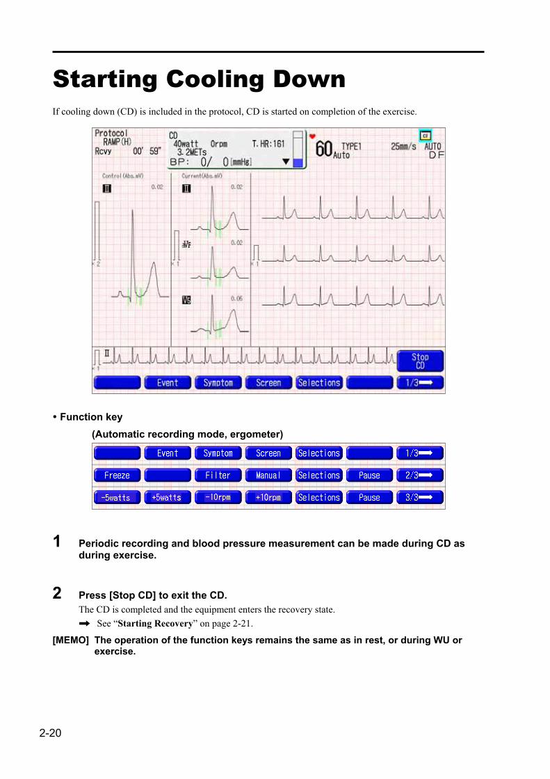
Starting Cooling Down If cooling down (CD) is included in the protocol, CD is started on completion of the exercise.
� Function key (Automatic recording mode, ergometer)
1 Periodic recording and blood pressure measurement can be made during CD as during exercise.
2 Press [Stop CD] to exit the CD. The CD is completed and the equipment enters the recovery state.
See “Starting Recovery” on page 2-21.
[MEMO] The operation of the function keys remains the same as in rest, or during WU or exercise.

Chapter 2 Conducting a stress test
2-21
Starting Recovery Recovery is started on completion of the exercise or cooling down (CD).
� Function key (Automatic recording mode)
1 Periodic recording and blood pressure measurement can be made during recovery as during exercise.
2 Press [End Recovery] to exit the recovery. Recovery is exited and the exercise is completed, which allows you to print or file a test report.
See “Printing and Filing a Test Report” on page 2-23.
[MEMO] The operation of the function keys remains the same as in rest, or during WU or exercise.

2-22
Exiting Recovery Press the [End Recovery] button to exit the recovery.
� Function key (Automatic recording mode)
1 Press [End Recovery] to exit the recovery. Recovery is exited and the exercise is completed, which allows you to print or file a test report.
See “Printing and Filing a Test Report” on page 2-23.
[MEMO] The operation of the function keys remains the same as in rest, or during WU or exercise.

Chapter 2 Conducting a stress test
2-23
Printing and Filing a Test Report After the stress test is completed, a test report can be printed or filed.
� Function key (Automatic recording mode)

2-24
1 Press [Edit BP] to edit (change) the blood pressure value measured. The blood pressure value can be edited during exercise or recovery.
See “Editing Blood Pressure Value” on page 2-26.
2 Press [Edit Event] to edit (delete) the event waveforms stored in the memory. The event waveforms registered during a stress test can be edited. If there is no event waveforms, [Edit Event] is not displayed.
See “Editing Event Waveforms” on page 2-27.
3 Press [Store] to store the test data. Press a desired media for storing the data on the storage window, and the test data will be stored in a floppy disk, IC card, or DMS.
4 Press [Report] to select the test report to be printed. See “Selecting Test Report” on page 2-25.
Note that the data cannot be output if the duration of exercise and recovery is less than 1 minute in total. The exercise prescription report cannot be output if the duration of exercise is less than the specified period of time.
5 Press [Return to Rest] to exit stress tests and return to the state at rest. A confirmation message window appears, asking you whether you want to exit the stress test or not. Press [Execute] to exit the stress test and return to the state at rest.
[NOTE] The data for the stress test is deleted if the test is exited here. Be sure to output or store the report before exiting.
Chapter 2 Conducting a stress test
2-25
Selecting Test Report
1
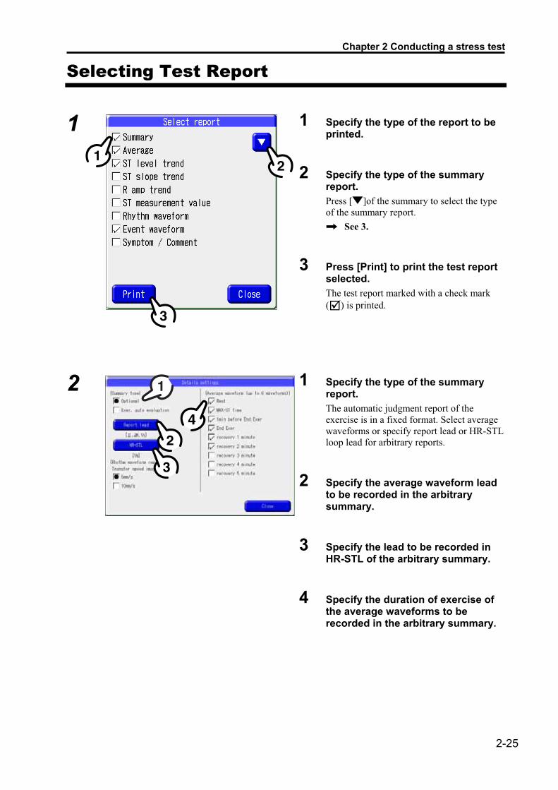
�
1 Specify the type of the report to be printed.
2 Specify the type of the summary report. Press [ ]of the summary to select the type of the summary report.
See 3.
3 Press [Print] to print the test report selected. The test report marked with a check mark (�) is printed.
2
1 Specify the type of the summary report. The automatic judgment report of the exercise is in a fixed format. Select average waveforms or specify report lead or HR-STL loop lead for arbitrary reports.
2 Specify the average waveform lead to be recorded in the arbitrary summary.
3 Specify the lead to be recorded in HR-STL of the arbitrary summary.
4 Specify the duration of exercise of the average waveforms to be recorded in the arbitrary summary.

2-26
Editing Blood Pressure Value
The blood pressure value entered before the stress test can be edited on the edit BP window.
1 Press [ ] of the blood pressure value to be edited, and the numeric value entry window appears. Enter the blood pressure value on the window.
2 Press [ ] to display the next page. Note that [ ] is not displayed on the last page.
3 Press [ ] to display the previous page. Note that [ ] is not displayed on the first page.
4 Press [Close] to close the edit BP window.

Chapter 2 Conducting a stress test
2-27
Editing Event Waveforms
The event waveform registered at the time of the stress test can be checked or deleted on the event edit window. In the event edit window, the waveforms from the
rhythm lead (1ch) stored in the memory when the [Event] key is pressed or when the event conditions such as arrhythmia, ST level value, blood pressure, and heart rate are satisfied are displayed.
1 Press [Delete] to delete the event waveform currently displayed. The event waveform is deleted, and the next event waveform appears. Note that if the last event waveform is deleted, the previous one is displayed.
2 Press [ ] or [ ]. The next or the previous event waveform is displayed.
3 Press [Close]. The event edit window is closed.

2-28
Exiting the Test
When the test report is printed and filed, exit the test, and the equipment returns to the state at rest.
1 Press [Return to Rest]. A confirmation message window appears.
2 Press [Execute] to exit the test. If the test is completed, the test data is deleted, and preparation for the next test is started.

Chapter 2 Conducting a stress test
2-29
Retrieving Data Stored in a File Press [Retrieve data], and you can edit or print the blood pressure value, event waveforms and patient information stored in the PC card or CF card.
See the operation manual supplied with the main unit for [Retrieve data].
1 Select stress data and then press [Print] to print the report.
�
1 Select stress data, and press [Edit].The editing window appears. Then select one from [Edit ID], [Edit BP], and [Event edit] to open their respective windows.
See the operation manual supplied with the main unit for [Edit ID].
See “Editing Blood Pressure Value” on page 2-26 for [Edit BP].
See “Editing Event Waveforms” on page 2-27 for [Event edit].
2 Press [Store] to store the data.
3 Press [Report] to print the data.

2-30
Chapter 3 Setting the Stress Test
This chapter describes the settings for the stress test such as protocols, exercise devices, and event conditions.
Editing Protocols............................................................... 3-2 When the Ergometer is selected as an exercise device..3-2 When the Treadmill is selected as an exercise device ....3-5
Setting.................................................................................. 3-8 How to Operate the Setting Screen .....................................3-8 Setting the Stress Test............................................................3-9
General .....................................................3-9 Recording ...............................................3-10 Recording – Details ...............................3-11 Display....................................................3-11 Event Conditions ...................................3-12 Event Conditions – Details....................3-13 ST Measurement ....................................3-14
Exercise Protocol ............................................................ 3-15 Exercise protocol List...........................................................3-15

3-2
Editing Protocols When the Ergometer is selected as an exercise device
A desired exercise protocol can be selected from 6 types, and the number of exercise stages, contents of the exercise, recording time, blood pressure measurement time, etc..
1
1 Select an exercise protocol. The figure on the left is a typical display of each stage when the “RAMP (H)” protocol is selected.
2 Press [Template], and select a template for the protocol.
3 Press [Protocol name], and you can change the name of the protocol such as RAMP1.
4 Press [WU], or [1] to [11], and you can change the contents of each stage.
5 Press [12 - CD], and you can change the contents of each stage including the 12 to 22 stages and CD.
6 Press [Measured Time], and you can change the time for recording, blood pressure measurement, and ST data storage.
See “Set the recording time” on page 3-4.
7 Press [Close] to save the protocol information.

Chapter 3 Setting the Stress Test
3-3
2 Select a template for the protocol.
3 Enter the name of the protocol.
Enter the name of the protocol using the full keys on the operation panel.
See the operation manual supplied with the main unit for the function of the full keys.
4 Edit the stage.
Enter the duration of each stage (Unit: minute), wattage (WATT), with/without RAMP exercise, and the number of pitches.If “0” is select as duration, the stage is not executed. ��Press [ ] or [ ] to shift the item to be
entered. ��Press [Clear] to delete all the contents
entered. ��Press [DEL] to initialize the contents of
the item. ��Press [Close] to abort the entry, discarding
the contents entered. ��Press [Enter] to exit the entry, saving the
contents entered.

3-4
5 Set the time of each measurement for the specified protocol. On the measurement time window shown below, set recording time, BP measurement time, ST data store time, and representative date of the stage and time to obtain representative data.
1 Set the recording time ��Set the time for starting the periodic
recording for each of during exercise and recovery.
��If the intervals are specified, recording is made at specified intervals after the exercise/recovery is started. (See the figure on the left.)
��Specify desired intervals on the interval setting area shown by the figure on the left.
��If a time is specified, recording is made at that time after the exercise/recovery is started. Ten times can be specified for recording during exercise or recovery in the set time window shown on the left. Press and enter time (Unit: minute), and then press [Confirm]. The figure on the left represents the case in which 0 (immediately after), 1, 3, 5, and 7 minutes are specified.
2 Set the BP measurement time. ��Specify the blood pressure measurement
time for each exercise and recovery, following the same procedure as the setting of recording time described above.
��If an automatic BP monitor is connected, specify the time for starting the measurement.
3 Set the ST data store time. ��Set the time intervals for ST data
measurement, following the same procedure as the setting of the recording time.
��The ST measurement obtained at the specified time is printed in an ST measurement value report.
4 Set the representative data of the stage acquisition timing. ��When “Yes” is selected under “Exercise
each stage,” set the operation timing for the recording time, BP measurement time, and ST data store time.
5 Set the representative data of the stage acquisition time (timing). ��When “Set time” is enabled in
representative data of the stage, set the elapsed time of the stage to be operated.
Chapter 3 Setting the Stress Test
3-5
When the Treadmill is selected as an exercise device
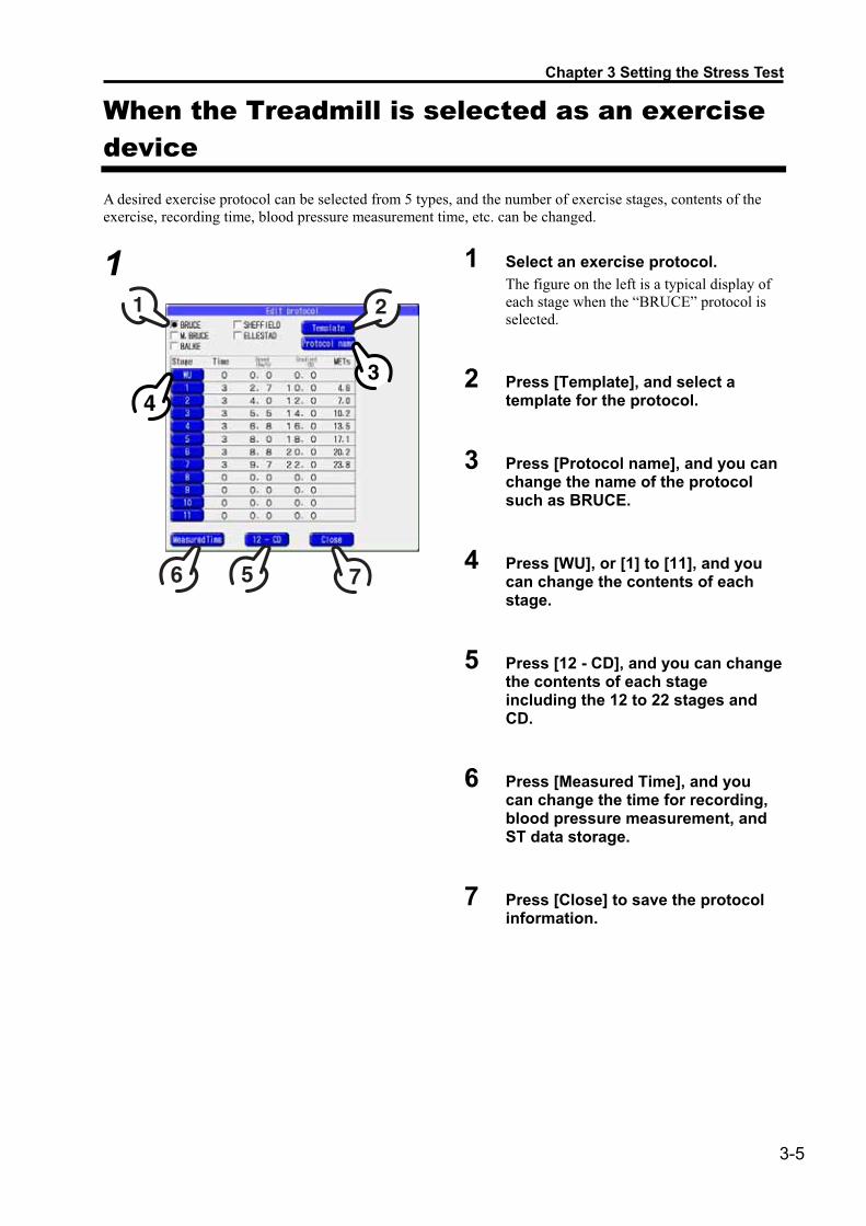
A desired exercise protocol can be selected from 5 types, and the number of exercise stages, contents of the exercise, recording time, blood pressure measurement time, etc. can be changed.
1
1 Select an exercise protocol. The figure on the left is a typical display of each stage when the “BRUCE” protocol is selected.
2 Press [Template], and select a template for the protocol.
3 Press [Protocol name], and you can change the name of the protocol such as BRUCE.
4 Press [WU], or [1] to [11], and you can change the contents of each stage.
5 Press [12 - CD], and you can change the contents of each stage including the 12 to 22 stages and CD.
6 Press [Measured Time], and you can change the time for recording, blood pressure measurement, and ST data storage.
7 Press [Close] to save the protocol information.

3-6
2 Select a template for the protocol.
3 Enter the name of the protocol.
Enter the name of the protocol using the full keys on the operation panel.
See the operation manual supplied with the main unit for the function of the full keys.
4 Edit the stage.
Enter the duration (Unit: minute), speed (km/h), (Mile/h), and gradient (%) of each stage. If “0” is selected as duration, the stage is not executed. ��Press [ ] or [ ] to shift the item to be
entered. ��Press [Clear] to delete all the contents
entered. ��Press [DEL] to initialize the contents of
the item. ��Press [Close] to abort the entry, discarding
the contents entered. ��Press [Enter] to exit the entry, saving the
contents entered.

Chapter 3 Setting the Stress Test
3-7
5 Set the time of each measurement for the specified protocol. On the measurement time window shown below, set recording time, BP measurement time, ST data store time, and representative date of the stage and time to obtain representative data.
1 Set the recording time ��Set the time for starting the periodic
recording for each exercise and recovery.��If the intervals are specified, recording is
made at specified intervals after the exercise/recovery is started. (See the figure on the left.)
��Specify desired intervals on the interval setting area shown by the figure on the left.
��If a time is specified, recording is made at that time after the exercise/recovery is started. Ten times can be specified for recording during exercise or recovery in the set time window shown on the left. Press and enter time (Unit: minute), and then press [Confirm]. The figure on the left represents the case in which 0 (immediately after), 1, 3, 5, and 7 minutes are specified.
2 Set the BP measurement time. ��Specify the blood pressure measurement
time for each exercise and recovery, following the same procedure as the setting of recording time described above.
��If an automatic BP monitor is connected, specify the time for starting the measurement.
3 Set the ST data store time. ��Set the time intervals for ST data
measurement, following the same procedure as the setting of the recording time.
��The ST measurement obtained at the specified time is printed in an ST measurement value report.
4 Set the representative data of the stage acquisition timing. ��When “Yes” is selected under “Exercise
each stage,” set the operation timing for recording time, BP measurement time, and ST data store time.
5 Set the representative data of the stage acquisition time (timing). ��When “Set time” is enabled in
representative data of the stage, set the elapsed time of the stage to be operated.

3-8
SettingHow to Operate the Setting Screen
Set each item by selecting the desired settings or entering numeric values.
1 Press [Stress test] on the Settings>List items screen.
2 Press the item to be set to select it.
3 Press a desired setting to change it.
4 Press [Goto exam] to return to the measurement screen. To set other items successively, repeat the above operation. [Goto exam]: Returns to the
measurement screen. If the setting has been changed, a confirmation message window appears, asking you whether you want to store the change.
[Reset settings]: Restores the default setting.
[Details settings]: You can set more details.[Back]: Returns to the previous
screen. If the setting has been changed, a confirmation message window appears, asking you whether you want to store the change.
: Prints the setting contents of the stress test.

Chapter 3 Setting the Stress Test
3-9
Setting the Stress Test
[MEMO] The items enclosed in square brackets [ ] are default settings.
General Item Description Setting range
Lead method Specify a lead method. [Standard 12 leads] Cabrera lead Bipolar chest lead
Load device Specify the load device used. [Ergometer] Treadmill
Ergometer Specify the type of ergometer used. [FUKUDA protocol] Ergoline (BP) Ergoline (None BP)
Treadmill Specify the type of treadmill used. [FUKUDA protocol] TM-425 RAM-770CE
Unit of distance Specify the unit of distance of the treadmill. [km] Mile
Blood pressure monitor
Specify the type of the blood pressure monitor used. [FUKUDA protocol] Ergoline (BP) Tango
BP measurement start time
Specify the starting time of blood pressure measurement when it is measured automatically at specified intervals.
0 sec. 30 sec. before [45 sec. before] 60 sec. before 90 sec. before
Serial port 1 Specify the device connected to Serial port 1. [None] ID reader 1 ID reader 2 Ergometer Treadmill BP monitor
Serial port 2 Specify the device connected to Serial port 2. [None] ID reader 1 ID reader 2 Ergometer Treadmill BP monitor
Serial port 3 Specify the device connected to Serial port 3. [None] ID reader 1 ID reader 2 Ergometer Treadmill BP monitor
Automatic storing Specify whether the test result is to be automatically stored in a media.
Yes [No]
Storage media Specify a media in which the data is to be stored. Multiple media can be specified.
[PC card] CF card DMS

3-10
Recording Item Description Setting range
Automatic recording report
Specify the format of the automatic recording from the waveform report specified in automatic recording type and the average recording.
See “List setting>Recording format>12-lead auto recording” for TYPES 1 to 5.
[TYPE1], TYPE2, TYPE3, TYPE4, TYPE5 [Record average]
Scheduled recording report
Specify the format of the scheduled recording from the waveform report specified in automatic recording type and the average recording.
See “List setting>Recording format>12-lead auto recording” for TYPES 1 to 5.
TYPE1, TYPE2, TYPE3, TYPE4, TYPE5 [Record average]
Compressed recording Specify the method of the compression recording between periodic recordings. None: Compression recording is not performed. 5 mm/s: Compressed record is printed at 5 mm/s. 10 mm/s: Compressed record is printed at 10 mm/s. 12.5 mm/s: Compressed record is printed at 12.5
mm/s.
[None] 5 mm/s 10 mm/s 12.5 mm/s
Record final report A test report is automatically printed at the end of the test.
Yes [No]
Final examination report
Specify the type of the test report to be printed. Multiple types can be specified Summary report Average report ST level trend report ST slope trend report R amp trend report ST measurement value report Rhythm waveform report Event waveform report Symptom/comment report
[Summary] [Average] [ST level trend] ST slope trend R amp trend ST measurement Rhythm waveform [Event waveform] Symptom/comment

Chapter 3 Setting the Stress Test
3-11
Recording – Details Specify the contents of the editing of the summary report.
Item Description Setting range
Summary type Specify the type of the summary report. [Optional] Exer. auto evaluation
Report lead Specify the leads to be printed in the summary report. [II aVF V5] I II III aVR, aVL, aVF V1, V2, V3, V4, V5, V6
HR-STL Specify the HR-STL loop lead (s) to be printed in the summary report.
[V5] I, II, III aVR, aVL, aVF V1, V2, V3, V4, V5, V6
Average waveform Specify the average waveform to be printed in the summary report. A maximum of 6 waveforms can be specified.
[Rest] [MAX-ST time] [1 minute before End Exer] [End Exer] [Recovery 1 min.] [Recovery 2 min.] Recovery 3 min. Recovery 4 min. Recovery 5 min.
Rhythm waveform report synchronizing speed
Specify the waveform transfer speed on the rhythm waveform report.
[5 mm/s] 10 mm/s
Display Item Description Setting range
Screen format Specify the format of the screen to be displayed during the stress/exercise test.
See “List settings>12 Leads>Post/display” for screens 1 to 3.
[Average waveform (1ch)] Average waveform (3ch) Average waveform (12ch) 6ch � 2 Optional format 1 Optional format 2 Optional format 3 Time-series waveform
Enlarged average waveform
Specify the lead to be displayed magnified with average (1ch).
[ch.1], ch.2, ch.3
Operation button available
Specify the operation button to be used during exercise. [BP monitor, event, symptom] [Stage up/down/hold] [�5 watts, �10 rpm]

3-12
Event Conditions Item Description Setting range
Stop load condition Specify the conditions for stopping exercise. Multiple conditions can be specified
[Arrest, VT] [V-Run]
[V-Frequent] [ST elevation]
[ST depression] [Target HR]
Event flag setting condition
Specify the conditions for storing data in the memory. Multiple conditions can be specified.
[Arrest, VT] [V-Run]
[V-Frequent] [ST elevation]
[ST depression]
Alarm record condition
Specify the conditions for recording alarms. Multiple conditions can be specified.
[Arrest, VT] [V-Run]
[V-Frequent] [ST elevation]
[ST depression]
Alarm sound condition
Specify the conditions for emitting alarm sound. Multiple conditions can be specified.
[Arrest, VT] [V-Run]
[V-Frequent] [ST elevation]
[ST depression] BP drop
Systolic BP Diastolic BP
Chapter 3 Setting the Stress Test
3-13
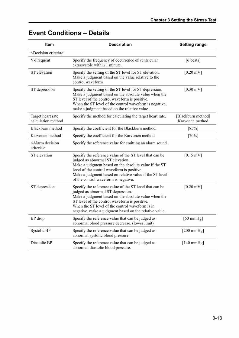
Event Conditions – Details Item Description Setting range
<Decision criteria>
V-Frequent Specify the frequency of occurrence of ventricular extrasystole within 1 minute.
[6 beats]
ST elevation Specify the setting of the ST level for ST elevation. Make a judgment based on the value relative to the control waveform.
[0.20 mV]
ST depression Specify the setting of the ST level for ST depression. Make a judgment based on the absolute value when the ST level of the control waveform is positive. When the ST level of the control waveform is negative, make a judgment based on the relative value.
[0.30 mV]
Target heart rate calculation method
Specify the method for calculating the target heart rate. [Blackburn method] Karvonen method
Blackburn method Specify the coefficient for the Blackburn method. [85%]
Karvonen method Specify the coefficient for the Karvonen method [70%]
<Alarm decision criteria>
Specify the reference value for emitting an alarm sound.
ST elevation Specify the reference value of the ST level that can be judged as abnormal ST elevation. Make a judgment based on the absolute value if the ST level of the control waveform is positive. Make a judgment based on relative value if the ST level of the control waveform is negative.
[0.15 mV]
ST depression Specify the reference value of the ST level that can be judged as abnormal ST depression. Make a judgment based on the absolute value when the ST level of the control waveform is positive. When the ST level of the control waveform is in negative, make a judgment based on the relative value.
[0.20 mV]
BP drop Specify the reference value that can be judged as abnormal blood pressure decrease. (lower limit)
[60 mmHg]
Systolic BP Specify the reference value that can be judged as abnormal systolic blood pressure.
[200 mmHg]
Diastolic BP Specify the reference value that can be judged as abnormal diastolic blood pressure.
[140 mmHg]

3-14
ST Measurement Item Description Setting range
Arrhythmia detection lead
Specify the leads to be used for detecting arrhythmia. [II V5] I, II, III
aVR, aVL, aVF V1, V2, V3 V4, V5, V6
ST measurement point decision
Specify the method for determining the ST measurement point. Fixed: The measurement points are determined with the
control waveform. Auto: The measurement points are determined with the
control waveform based on the RR intervals.
[Fixed] Auto
Display measured values
Specify the method for displaying the current waveform measurement. Absolute value: Displays the current waveform
measurement. Relative value: Displays the deviation from the control
waveform.
[Absolute value] Relative value
ST reference point Specify the value before the QRS waveform recognition position.
[60 ms] Before R waveform: 20 to 200 ms
STj point Specify the value after the QRS waveform recognition position.
[60 ms] After R waveform: 20 to 200 ms
ST level point Specify the value before the STj point [40 ms] After STj point: 0 to 280 ms
ST slope point Specify the value after the STj point. [60 ms] After STj point: 40 to 280 ms

Chapter 3 Setting the Stress Test
3-15
Exercise Protocol Exercise protocol List
The equipment incorporates the following exercise protocol templates.
��Ergometer � RAMP (H)
Stage No. Time (min.) Wattage (WATT) RAMP
exercisePITCH (rpm)
WU 2 20 OFF 60 1 2 60 ON 60 2 2 100 ON 60 3 2 140 ON 60 4 2 180 ON 60
5 to 22 0 0 OFF 0 CD 2 40 OFF
� RAMP (M)
Stage No. Time (min.) Wattage (WATT) RAMP
exercisePITCH (rpm)
WU 2 20 OFF 60 1 2 50 ON 60 2 2 80 ON 60 3 2 110 ON 60 4 2 140 ON 60
5 to 22 0 0 OFF 0 CD 2 30 OFF
� RAMP (L)
Stage No. Time (min.) Wattage (WATT) RAMP
exercisePITCH (rpm)
WU 2 20 OFF 60 1 2 40 ON 60 2 2 60 ON 60 3 2 80 ON 60 4 2 100 ON 60
5 to 22 0 0 OFF 0 CD 2 20 OFF

3-16
� STEP (H)
Stage No. Time (min.) Wattage (WATT) RAMP
exercisePITCH (rpm)
WU 2 0 OFF 0 1 2 50 OFF 60 2 2 100 OFF 60 3 2 150 OFF 60 4 2 200 OFF 60
5 to 22 0 0 OFF 0 CD 2 50 OFF
� STEP (M)
Stage No. Time (min.) Wattage (WATT) RAMP
exercisePITCH (rpm)
WU 2 0 OFF 0 1 2 50 OFF 60 2 2 75 OFF 60 3 2 100 OFF 60 4 2 125 OFF 60
5 to 22 0 0 OFF 0 CD 2 50 OFF
� STEP (L)
Stage No. Time (min.) Wattage (WATT) RAMP
exercisePITCH (rpm)
WU 2 0 OFF 0 1 2 25 OFF 60 2 2 50 OFF 60 3 2 75 OFF 60 4 2 100 OFF 60
5 to 22 0 0 OFF 0 CD 2 25 OFF

Chapter 3 Setting the Stress Test
3-17
� RAMP 1
Stage No. Time (min.) Wattage (WATT) RAMP
exercisePITCH (rpm)
WU 1 40 OFF 60 1 2 60 ON 60 2 2 80 ON 60 3 2 100 ON 60 4 2 120 ON 60 5 2 150 ON 60 6 2 160 ON 60 7 2 180 ON 60 8 2 200 ON 60 9 2 220 ON 60
10 2 240 ON 60 11 2 260 ON 60
12 to 22 0 0 OFF 0 CD 3 40 OFF
� RAMP 2
Stage No. Time (min.) Wattage (WATT) RAMP
exercisePITCH (rpm)
WU 1 50 OFF 60 1 2 75 ON 60 2 2 100 ON 60 3 2 125 ON 60 4 2 150 ON 60 5 2 175 ON 60 6 2 200 ON 60 7 2 225 ON 60 8 2 250 ON 60
9 to 22 0 0 OFF 0 CD 3 50 OFF

3-18
� RAMP 3
Stage No. Time (min.) Wattage (WATT) RAMP
exercisePITCH (rpm)
WU 1 40 OFF 60 1 1 60 ON 60 2 1 80 ON 60 3 1 100 ON 60 4 1 120 ON 60 5 1 150 ON 60 6 1 160 ON 60 7 1 180 ON 60 8 1 200 ON 60 9 1 220 ON 60
10 1 240 ON 60 11 1 260 ON 60
12 to 22 0 0 OFF 0 CD 3 40 OFF
� STEP 1
Stage No. Time (min.) Wattage (WATT) RAMP
exercisePITCH (rpm)
WU 1 50 OFF 60 1 3 50 OFF 60 2 3 75 OFF 60 3 3 100 OFF 60 4 3 125 OFF 60 5 3 150 OFF 60 6 3 175 OFF 60 7 3 200 OFF 60
8 to 22 0 0 OFF 0 CD 3 50 OFF
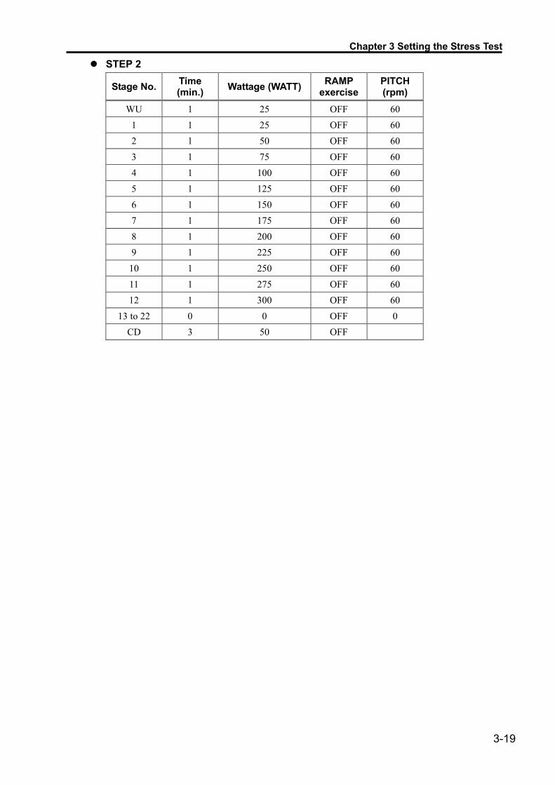
Chapter 3 Setting the Stress Test
3-19
� STEP 2
Stage No. Time (min.) Wattage (WATT) RAMP
exercisePITCH (rpm)
WU 1 25 OFF 60 1 1 25 OFF 60 2 1 50 OFF 60 3 1 75 OFF 60 4 1 100 OFF 60 5 1 125 OFF 60 6 1 150 OFF 60 7 1 175 OFF 60 8 1 200 OFF 60 9 1 225 OFF 60
10 1 250 OFF 60 11 1 275 OFF 60 12 1 300 OFF 60
13 to 22 0 0 OFF 0 CD 3 50 OFF

3-20
� Treadmill � BRUCE
Speed Stage No. Time (min.) (km/h) (mile/h)
Gradient (%)
WU 0 0.0 0.0 0.0 1 3 2.7 1.7 10.0 2 3 4.0 2.5 12.0 3 3 5.5 3.4 14.0 4 3 6.8 4.2 16.0 5 3 8.0 5.0. 18.0 6 3 8.8 5.5 20.0 7 3 9.7 6.0 22.0
8 to 22 0 0.0 0.0 0.0 CD 3 0.0 0.0 0.0
� M. BRUCE Speed Stage No. Time
(min.) (km/h) (mile/h) Gradient
(%)
WU 0 0.0 0.0 0.0 1 3 2.7 1.7 10.0 2 3 4.0 2.5 12.0 3 3 5.5 3.4 14.0 4 3 6.1 3.8 14.0 5 3 6.8 4.2 16.0 6 3 8.0 5.0 18.0 7 3 8.8 5.5 20.0 8 3 9.5 6.0 22.0
9 to 22 0 0.0 0.0 0.0 CD 3 0.0 0.0 0.0

Chapter 3 Setting the Stress Test
3-21
� BALKE Speed Stage No. Time
(min.) (km/h) (mile/h) Gradient
(%)
WU 0 0.0 0.0 0.0 1 2 5.5 3.4 2.0 2 2 5.5 3.4 4.0 3 2 5.5 3.4 6.0 4 2 5.5 3.4 8.0 5 2 5.5 3.4 10.0 6 2 5.5 3.4 12.0 7 2 5.5 3.4 14.0 8 2 5.5 3.4 16.0 9 2 5.5 3.4 18.0
10 2 5.5 3.4 20.0 11 2 5.5 3.4 22.0 12 2 5.5 3.4 24.0 13 2 5.5 3.4 26.0
14 to 22 0 0.0 0.0 0.0 CD 3 0.0 0.0 0.0
� SHEEFIELD Speed Stage No. Time
(min.) (km/h) (mile/h) Gradient
(%)
WU 0 0.0 0.0 0.0 1 3 2.7 1.7 0.0 2 3 2.7 1.7 5.0 3 3 2.7 1.7 10.0 4 3 4.0 2.5 12.0 5 3 5.5 3.4 14.0 6 3 6.8 4.2 16.0 7 3 8.0 5.0 18.0 8 3 8.8 5.5 20.0
9 to 22 0 0.0 0.0 0.0 CD 3 0.0 0.0 0.0
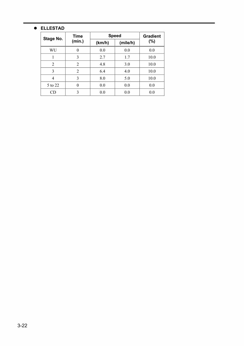
3-22
� ELLESTAD Speed Stage No. Time
(min.) (km/h) (mile/h) Gradient
(%)
WU 0 0.0 0.0 0.0 1 3 2.7 1.7 10.0 2 2 4.8 3.0 10.0 3 2 6.4 4.0 10.0 4 3 8.0 5.0 10.0
5 to 22 0 0.0 0.0 0.0 CD 3 0.0 0.0 0.0

Chapter 4 Report
This chapter provides details of various reports.
Waveforms + Average Report...............................................4-2 Alarm Report ............................................................................4-3 ST Summary Report (Option) ...............................................4-4 ST Summary Report (Automatic Exercise Judgment) ....4-5 Average Report........................................................................4-6 ST Level Trend Report............................................................4-7 ST Slope Trend Report...........................................................4-8 R Amplitude Trend Report.....................................................4-9 ST Measurement Value Report...........................................4-10 Rhythm Waveform Report...................................................4-11 Event Waveform Report.......................................................4-12 Symptom/Comment Report ................................................4-13

4-2
Waveforms + Average Report
��The waveforms + average report is printed when average recording is specified in the scheduled recording report and automatic recording report settings.
See “Setting, Recording” on page 3-10.
��The realtime waveform (for 4 seconds) and the average waveform of I to aVF and V1 to V6 leads are recorded. The marking lines for the ST reference points, ST level points, and ST slope points are overwritten on the average waveform, and the ST measurements are printed.
��The average waveform, which is the latest waveform on the report, is not created only from the recorded realtime waveforms, but obtained through a 16-beat shift addition processing.
�

Chapter 4 Report
4-3
Alarm Report
��An alarm report is recorded when alarm recording conditions are satisfied.
�

4-4
ST Summary Report (Option)
��A maximum of 6 average waveforms selected can be recorded.
��If there is no average waveform that corresponds to the minutes/seconds of the set time such as MAX-ST at forced termination, the average waveform close to it is recorded.
��The HR-STL loop is recorded.
�
��The report slightly differs from the example shown below when a treadmill is used as an exercise device.
[Exercise data] [Treadmill]
�

Chapter 4 Report
4-5
ST Summary Report (Automatic Exercise Judgment)
��A maximum of 6 average waveforms selected can be recorded.
��If there is no average waveform that corresponds to the minutes/seconds of the set time such as 1 minute before forced exercise termination, the average waveform close to it recorded.
��The V5 HR-STL loop is recorded.
��The ST level measurement of V5 lead and the result of the automatic stress test judgment are recorded.
�
��The report slightly differs from the example shown below when a treadmill is used as an exercise device.
[Exercise data] [Treadmill]

4-6
Average Report
��The average waveform stored as ST data is recorded in a report.
�

Chapter 4 Report
4-7
ST Level Trend Report
��The heart rate trend, blood pressure, and ST level are recorded.
��The double product (D.P.) is plotted.
[MEMO] The D.P., which is considered to be in proportion to the oxygen consumption of the cardiac muscle calculated by the expression, Heart rate × Systolic blood pressure, can be used for determining the intensity of exercise for exercise treatment.
�

4-8
ST Slope Trend Report
��The heart rate trend, blood pressure, and ST slope are recorded.
��The double product (D.P.) is plotted.
�

Chapter 4 Report
4-9
R Amplitude Trend Report
��The heart rate trend, blood pressure, and R amplitude are recorded.
��The double product (D.P.) is plotted.
��
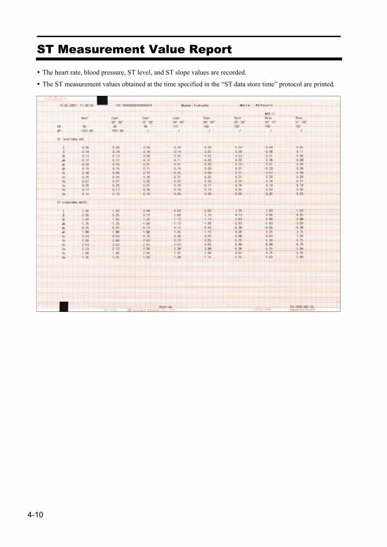
4-10
ST Measurement Value Report
��The heart rate, blood pressure, ST level, and ST slope values are recorded.
��The ST measurement values obtained at the time specified in the “ST data store time” protocol are printed.
�

Chapter 4 Report
4-11
Rhythm Waveform Report
��The waveforms of the lead specified as the 1 channel of the arrhythmia detection leads are recorded.
��Specify either 5 mm/s or 10 mm/s as the waveform transfer speed image.
�
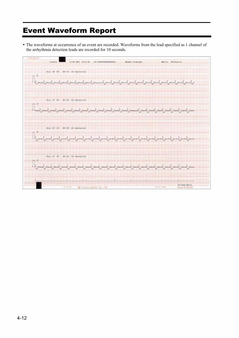
4-12
Event Waveform Report
��The waveforms at occurrence of an event are recorded. Waveforms from the lead specified as 1 channel of the arrhythmia detection leads are recorded for 10 seconds.
�

Chapter 4 Report
4-13
Symptom/Comment Report
��The symptoms, RPE, and comments entered during the test are recorded.
�

4-14
Chapter 5 Installation
This chapter describes the installation function.
Outline of Installation..............................................................5-3 Installation.................................................................................5-4 Uninstallation ...........................................................................5-6 Error Messages That May Appear When Installing the
Software...............................................................................5-8

5-2
This chapter describes the method of installing the optional software onto the FX-7542.
WARNING This optional software is intended for the FX-7542. Note that if the software is installed onto an incompatible device, the main unit program may not operate properly.
CAUTION This optional software cannot be installed in 2 or more FX-7542 units. Install the software in only one FX-7542 unit. Uninstall (delete) the software before installing it onto another FX-7542 unit. Cautions on static electricity This optional software is supplied contained in a CF card. A CF card is a very sensitive device susceptible to damage due to static electricity. If a part of human body touches the metallic part of the CF card, static electricity may be discharged to the parts of the card or within the circuit, thus damaging the data contained in the CF card. To protect the CF card against damage due to static electricity, be sure to follow the instructions shown below. � To discharge the static electricity developing in your body, touch the potential equalization terminal
before starting the work. � Handle the CF card, holding the edge. Never touch the metallic part of the card. � Store the CF card used for installation in a box that contained the product.

Chapter 5 Installation
5-3
Outline of Installation
The optional software can be installed or uninstalled as follows.
��New installation or upgrading the optional software. See “Installation” on page 5-4.
��Uninstalling the optional software before reinstalling it onto another device. See “Uninstallation” on page 5-6.
[How to insert the CF card]
SERIAL NO.
S N
FOR FX-7542
STRESS TEST SOFTWARE
FP-1003
FX-7542
CF card slot

5-4
Installation
This section describes the procedure for a new installation or upgrading the optional software.
[NOTE] Prepare a CF card for installing the optional software. [NOTE] Check that the software to be installed is the optional software for the FX-7542. If
incompatible software is installed, the main unit software may not operate properly.
1 Insert the CF card for installing the optional software into the CF card slot on the right side of the main unit, and then press the button to turn on the power.
2
Once the installation software is started, the screen shown on the left appears. Note that the “Board No.” in the installation card data is displayed only when the software is upgraded. It is not displayed during new installation.
3
Press the [Install] button, and a confirmation message window appears.

Chapter 5 Installation
5-5
4 Press the button to install the software. Press the [Cancel] button to stop installing the software. The following message appears once the installation is started.
[NOTE] Do not turn off the power while installation is in progress. Otherwise the equipment may become unusable.
[NOTE] Do not remove the CF card or turn off the power while installation is in progress. Otherwise installation may fail or the CF card may be damaged, disabling the main unit software or making the CF card unusable.
5 When installation is completed, the following message appears.
Installation was completed normally.
Please turn the power off.
6 Press down the button for 2 seconds or longer to turn off the power, and then remove the CF card.
7
Press the button to turn on the power. After the ECG starts, press the [Measurement mode] button to display the Measurement mode list, and check that the Measurement mode items of the optional software are included in the list.
8 Press the analysis item of the optional software to check that the installed optional mode can be entered.
Installation or upgrading and operation check of the optional software have now been completed.
See the operation manual of the optional software for details.

5-6
Uninstallation
This section describes the procedure of uninstalling (deleting) the optional software before reinstalling it onto another FX-7542 unit.
[NOTE] Prepare the CF card used for installing the optional software. If an incompatible CF card is used, the main unit software may become inoperable or the CF card may become unusable.
1 Insert the CF card into the CF card slot on the right side of the main unit, and then press the button to turn on the power.
2
Once the installation software is started, the screen shown on the left appears.
3
Press the [Uninstall] button, and a confirmation message window appears.

Chapter 5 Installation
5-7
4 Press the button to uninstall the software. Press the [Cancel] button to stop the uninstallation. Once the uninstallation is started, the following message appears.
[NOTE] Do not turn off the power while the optional software is being uninstalled. Otherwise the equipment may become unusable.
[NOTE] Do not remove the CF card or turn off the power while the software is being uninstalled. Otherwise the uninstallation may fail or the CF card may be damaged, disabling the main unit software or making the CF card unusable.
5 When uninstallation is completed, the following message appears.
The optional software was deleted normally.
Please turn the power off.
6 Press down the button for 2 seconds or longer to turn off the power, and then remove the CF card.
7 Press the button to turn on the power. Once the ECG starts, press the [Measurement mode] button to display the Measurement mode list, and check that the Measurement mode items of the optional software have been uninstalled.
The optional software has now been uninstalled.

5-8
Error Messages That May Appear When Installing the Software
This section describes the error messages that may appear when the software is installed.
If an error message appears while the software is installed, perform the operation again by referring to “Remedy” shown below.
��Cannot install on this model. Please turn the power off. Cause: Installation was attempted to this model, which does not support the optional software. Remedy: Contact Fukuda Denshi’s sales representative.
��Cannot install on this version. Please turn the power off. Cause: Installation was attempted to a version that does not support the optional software. Remedy: Contact Fukuda Denshi’s sales representative.
��Cannot install the optional software on this card as it has already been installed on another machine. Please turn the power off.
Cause: Installation was attempted to another ECG unit with the optional software card used for the installation.
Remedy: Purchase a new optional software, or uninstall the optional software installed in the ECG unit.
��The optional software has already been installed on this device. Please turn the power off.
Cause: Installation cannot be performed since the optional software has already been installed.
��The optional software is not installed. Please turn the power off. Cause: Uninstallation cannot be performed since the optional software has not been installed.
��Please insert the card used to install the optional software and try again. Please turn the power off.
Cause: Uninstallation was attempted with a card different from the one used for the installation of the optional software.
Remedy: Uninstall the software, inserting the card used for the installation of the optional software into the ECG unit.

Chapter 6 Appendix
This chapter provides major specifications of the stress test as well as details of the devices to be connected to the equipment.
Major Specifications ...............................................................6-2 Accessories..............................................................................6-3 Optional Items..........................................................................6-4 Alarms and Error Messages .................................................6-7

6-2
Major Specifications
1) Arrhythmia detection ��Arrhythmia detection is based on 2ch waveform data specified in arrhythmia detection lead system.
2) Average waveform generation (Measurement waveform) ��The average waveform is based on 16-beat addition average.
��The obtained average waveform is updated once every 15 seconds.
��If exercise is started in a state in which the average waveform is not generated, the waveform at rest immediately before is regarded as the control waveform.
3) ST measurement is performed as follows. ��ST level [mV]
����� point referenceat potential Electricpointt measuremen level STat potential Electric
��ST slope [mV/sec.]
ms 40pointt measuremen slope ST before ms 40at level STpointt measuremen slope STat level ST �����
��The ST measurement point varies depending on the R-R time of measurement if “Auto” is selected as “ST measurement point decision” in function setting
× waveformcontrol of timeR-R
timeR-Rpointt measuremen ST �
[ ] point STjpoint STj waveformcontrol ofpoint t measuremen ST ����
��If “Absolute value” is selected as “Display measured values” in function setting, the ST measurement is displayed as it is. If the display is set to “Relative value,” the deviation from the control waveform is displayed. Note that the control waveform measurement is displayed in “Absolute value” at all times.
4) METS can be calculated using the following expression. ��When the ergometer is used
3.5× [kg] Weight30012.24×[W] exercise ofAmount
METS�
�
* Note that if the weight of the patient has not been entered, METS is calculated with the weight of the patient assumed as 55 kg.
��When the treadmill is used
( ) 3.51.8× [m/min] Speed×[%] Slope0.1×[m/min] Speed3.5METS ����

Chapter 6 Appendix
6-3
Accessories
[NOTE] To achieve the best performance of the product, be sure to use consumables manufactured by Fukuda Denshi.
[NOTE] Inform us of the type and the name of the consumables you want to order. [MEMO] Accessories may be changed without prior notice for quality improvement.
No. Name Type Quantity Note
� CF card for installation FP-1003 1
2 Operation manual 1 This manual
1 2
SERIAL NO.S N
FOR FX-7542STRESS TEST SOFTWARE
FP-1003

6-4
Optional Items
[NOTE] The optional items shown below are not supplied with the software. Place an order separately for these items.
[MEMO] Optional items may be changed without prior notice for quality improvement.
Common set (Option)
No. Name Type Note
1 Input box for stress/exercise CIS-03BKPE/CIS-03BKPA
2 Clip electrode TE-171 Echo Rode II
3 Skin cream OA-426
1 2 3
ON OFF
BATTERY CHECK
CIS-03BKPE
BP monitor set (Option)
No. Name Type Note
1 Exercise BP monitor Tango
2 BP monitor connection cable CJ-439
3 Analog I/O Box CI-701
1 2 3

Chapter 6 Appendix
6-5
Ergometer set (Option)
No. Name Type Note
1 Ergometer Ergoselect 100P/100K Ergoselect 200P/200K Ergometrics er800/er900
2 Ergometer connection cable CJ-439 For Ergoselect 100P/100K For Ergoselect 200P/200K
3 Ergometer connection cable CJ-325 For Ergometrics er800/er900
4 Ergometer connection cable CJ-392 For Ergometrics er800/er900
1 2
ergoline
3 4
(Ergometrics er800/er900) Connect the CJ-392 connection cable and the CJ-325 connection cable together. Then, connect the other end of the CJ-392 connection cable to the ergometer and the other end of the CJ-325 connection cable to the RS-232C connector on the FP-1003.

6-6
Treadmill set (Option)
No. Name Type Note
1 Treadmill
TM-400 TM-425 770CE PM
2 Treadmill connection cable CJ-400
For TM-400 For TM-425 For 770CE For PM
1 2
Mad 770 CE
RAM

Chapter 6 Appendix
6-7
Alarms and Error Messages
The following alarms and error messages may appear in the stress test mode. If messages other than those shown below appear, see the operation manual supplied with the main unit.
� Alarm ��HR target reached.
Cause: The target heart rate set at the start of the test was reached.
��Arrhythmia occurred. (Arrest, VT)
��Arrhythmia occurred. (V-Run)
��Arrhythmia occurred. (VPC) Cause: Arrhythmia specified in the event conditions occurred.
��ST abnormality has occurred. (ST elevation)
��ST abnormality has occurred. (ST depression)
��ST abnormality has occurred. (ST elevation Alarm)
��ST abnormality has occurred. (ST depression Alarm) Cause: ST error specified in the event conditions occurred.
��Blood pressure abnormality has occurred. (Drop in blood pressure alarm)
��Blood pressure abnormality has occurred. (Systolic blood pressure alarm)
��Blood pressure abnormality has occurred. (Diastolic blood pressure alarm) Cause: Blood pressure error specified in the event conditions occurred.
6-8
� Error messages If an error message should appear during operation, attempt the operation again, referring to the “Remedy” shown below.
��Waiting for control data. Cause: An attempt was made to start the test in spite that the control waveform at rest had not been
registered. Remedy: Check that the control waveform appears on the screen before starting the test. If [Start WU]
or [Start Exercise] is pressed again in a state in which the control waveform has not been registered, a forcible test is then started, in which case the ST measurement and arrhythmia detection are disabled.
��Please set protocol. Cause: The test protocol was not set properly. Remedy: Check the setting contents of the test protocol.
��Stages cannot be changed. Cause: Stage Up was attempted in the final stage, or Stage Down was attempted in stage 1. Remedy: These operations are prohibited.
��Unable to change load. Cause: An attempt was made to change the exercise level while the exercise was temporarily
suspended in the stress test. Remedy: Restart exercise and then change the exercise level.
��BP monitor is not connected. Cause: A BP monitor was not connected to the equipment properly. Remedy: Check the state of the BP monitor and its connection with the equipment. Also check the
setting of the connection of the BP monitor.
��There is no data on blood pressure. Cause: No data had been registered when the blood pressure editing was attempted. Remedy: Check the protocol setting of the blood pressure measurement.
��Patient data has not been entered. Cause: The data of the patient was not entered. Remedy: Enter age, sex, weight, and daily exercise level of the patient.
��The load device is not ready. Cause: The ergometer or Treadmill was not connected to the equipment properly. Remedy: Check the state of the exercise device and its connection status with the equipment. Also
check the setting of the exercise device.


39-4, Hongo 3-chome, Bunkyo-ku, Tokyo, Japan Phone: +81-3-3815-2121 Fax: +81-3-3814-1222
4L0039580 200709