Venus Intrepid Tessera Lander - Lunar and Planetary Institute · National Aeronautics and Space...
55
National Aeronautics and Space Administration Mission Concept Study Report to the NRC Decadal Survey Inner Planets Panel Venus Intrepid Tessera Lander NASA-GSFC • NASA-ARC March 19, 2010 Science Co-Champions: Study Points of Contact: Dr. Martha S. Gilmore, Wesleyan University Dr. Lori S. Glaze, NASA’s Goddard Space Flight Center Charles L. Baker, NASA’s Goddard Space Flight Center George J. Tahu, NASA Headquarters
-
Upload
nguyendang -
Category
Documents
-
view
221 -
download
0
Transcript of Venus Intrepid Tessera Lander - Lunar and Planetary Institute · National Aeronautics and Space...

National Aeronautics and Space Administration
Mission Concept Study Report to the NRC Decadal Survey Inner Planets Panel
Venus Intrepid Tessera Lander
NASA-GSFC • NASA-ARC March 19, 2010
Science Co-Champions:
Study Points of Contact:
Dr. Martha S. Gilmore, Wesleyan UniversityDr. Lori S. Glaze, NASA’s Goddard Space Flight CenterCharles L. Baker, NASA’s Goddard Space Flight CenterGeorge J. Tahu, NASA Headquarters

RF CommBox
Raman/LIBS Laser TLSRaman/LIBSand Imaging Assy
MassSpectrometer
ASI
Panoramic Camera Assy
MechanismControl Electronics
Transponder
Avionics
Raman/LIBSElectronics
Magnetometer
Batteries
Carrier FlybySpacecraft
ProbeEntry
DropAeroshell
DropBackshell
Image onDescent
Land, SurfaceRock
Analysis
5 day ProbeCruise 100 km alt 60 km alt 50 km alt 15 km alt
T = 0 to2 hr
Venus Intrepid Tessera LanderMission Concept Study Report to the NRC Decadal Survey
Inner Planets Panel • March 15, 2010Concept Maturity Level: 4 • Cost Range: Low End Flagship
GSFC • ARC
Mission DrivingScience Objectives Measurement Instrument Functional Requirement
Characterize chemistry and mineralogy of the surface.
Place constraints on the size and temporal extent of a possible ocean in Venus’s past.
Characterize the morphology and relative stratigraphy of surface units.
Major, trace elements, mineralogy, NIR spectroscopy
Measure D/H ratio in atmospheric water, mineralogy and major element chemistry of surface rocks.
Visible and NIR observations of multiple surface units at cm to m scale spatial resolution.
Raman/LIBS; NIR (1.0 micron) descent imager below 1 km, Raman/LIBS context camera
NMS; TLS; Raman/LIBS
NIR (1.0 micron) descent imager and surface panoramic camera with ~5 �ltersfrom 550-1000 nm.
Access to tessera terrain, > 25 in situ sample measurements, sample context images
In situ sampling of the upper and lower (<16 km) atmosphere. Access to and measurement of tessera terrain.
Position of cameras to image the surface, while accommodating expected slopes, platform stability for clear images.
VITaLLander Aeroshell (Cruise Con�guration)
fact sheet
Pressure Vessel (Transparent View)
Nominal Mission:• Atlas V 551 • Launch on 11/2/2021 Launch Vehicle • Venus fly-by 4/7/2022• Type II trajectory • Descent/Landed science 7/29/2022
Probe timeline illustrates con�guration changes throughout science mission duration.
A low center of gravity Ring Lander in the Aeroshell
Note: At zenith the carrier S/C is directly overhead of the lander.
Backshell
Heatshield
Backshell/Lander Truss
Landing RingCrush RingCrush Plate
Snubber
Parachute System
2.5 mDiameter
10°
rock
30°
30°
72.7°
2.7°unallocated
DynamicLanding
Rock orBlock
MacroSlope
2.5 m
Ring design landing slope capability.
Venus North Pole(IAU)
Lander Entry, Descent,and Landing
Spacecraft at Lander EntryInterface (Landing Minus65 Minutes)
Spacecraft at Landing
Spacecraft at Periapsis(Landing Plus 85 Minutes)
Spacecraft at LandingPlus 120 Minutes
17°
48°
30°
Zenith12°

Raman/LIBS Survey Measurements and Context Images
Component Allow[%]
MaxMass[kg]
LanderLander Science Payload & Accum.Lander SubsystemsMechanical/StructureLanding SystemThermalPowerAvionicsRF CommAeroshellSpacecraftSatellite (S/C + Probe) Dry MassSatellite Wet MassLV Throw Mass available to lift Wet
105148
1002283603
671228
91051
84629483299
136663
1303368784
87163612
13791100384542005141
CBE[kg]
30%30%30%30%30%30%30%30%30%30%30%30%30%
Mass Breakdown
5°0’0”S5°0’0”S
4°0’0”S
83°0’0”E 84°0’0”E
84°0’0”E
0 15 30 60Kilometers
Ovda RegioMagellan SAR
Slopes (degrees)0.0 - 5.05.0 - 9.59.5 - 14.214.2 - 25.025.0 - 27.5
Slopes (degrees)0.0 - 5.05.0 - 9.59.5 - 14.214.2 - 25.025.0 - 27.5
Descent and Panoramic Imagery
SAR derived surface slopes inOvda Regio landing ellipse.
- 2 -Venus Intrepid Tessera Landerfact sheet
Backshell
Pressure Vessel
Inner &Outer Rings Heat
Shield
Carrier S/C
Drag Plate
1 m X-band
3 m S-band
Solar Array
φ2.5 m Ring
,'-)'
Descent Images
Approx. size of panoramic camera image FOV
1 km
10 cm Panoramic Camera FOV
Descent CameraFOV
Raman/LIBSFOV
0.86 meters at a distance of 2.5 meters from the Lander
Context Images
Exploded view of Carrier Spacecraft,Aeroshell, and Lander
i
Venus Intrepid Tessera Lander (VITaL)
TABLE OF CONTENTSExecutiveSummary 1
1 0ScientificObjectives 21.1 Scientific Questions and Objectives. . . . . . . . . . . . . . . . . . . . . . . . . . . . . 21.2 Science Traceability . . . . . . . . . . . . . . . . . . . . . . . . . . . . . . . . . . . . 21.3 Study Objectives . . . . . . . . . . . . . . . . . . . . . . . . . . . . . . . . . . . . . . 4
2 0High-LevelMissionConcept 42.1 Overview . . . . . . . . . . . . . . . . . . . . . . . . . . . . . . . . . . . . . . . . . . 42.2 Concept Maturity Level . . . . . . . . . . . . . . . . . . . . . . . . . . . . . . . . . . 5
3 0TechnicalOverview 63.1 Instrument Payload Implementation . . . . . . . . . . . . . . . . . . . . . . . . . . . . 63.2 Flight System . . . . . . . . . . . . . . . . . . . . . . . . . . . . . . . . . . . . . . . . 8
3.2.1 Concept of Operations and Mission Design . . . . . . . . . . . . . . . . . . . . . 83.2.2 Carrier Spacecraft . . . . . . . . . . . . . . . . . . . . . . . . . . . . . . . . . . .113.2.3 Entry and Descent Element. . . . . . . . . . . . . . . . . . . . . . . . . . . . . .113.2.4 Lander . . . . . . . . . . . . . . . . . . . . . . . . . . . . . . . . . . . . . . . .12
3.2.4.1 Lander Structure . . . . . . . . . . . . . . . . . . . . . . . . . . . . . . . .123.2.4.2 Lander Mechanical Static and Dynamic Analysis . . . . . . . . . . . . . . . .143.2.4.3 Lander Mechanisms . . . . . . . . . . . . . . . . . . . . . . . . . . . . . .153.2.4.4 Lander Thermal. . . . . . . . . . . . . . . . . . . . . . . . . . . . . . . . .163.2.4.5 Lander Optics . . . . . . . . . . . . . . . . . . . . . . . . . . . . . . . . .163.2.4.6 Lander Avionics. . . . . . . . . . . . . . . . . . . . . . . . . . . . . . . . .183.2.4.7 Lander Communications . . . . . . . . . . . . . . . . . . . . . . . . . . . .193.2.4.8 Lander Power . . . . . . . . . . . . . . . . . . . . . . . . . . . . . . . . . .193.2.4.9 Lander Mass and Data Rate. . . . . . . . . . . . . . . . . . . . . . . . . . .19
3.3 Ground Systems . . . . . . . . . . . . . . . . . . . . . . . . . . . . . . . . . . . . . .203.4 Key Trades . . . . . . . . . . . . . . . . . . . . . . . . . . . . . . . . . . . . . . . . .22
3.4.1 Lander Design Trade . . . . . . . . . . . . . . . . . . . . . . . . . . . . . . . . .223.4.2 Crushable Material Trade . . . . . . . . . . . . . . . . . . . . . . . . . . . . . . .233.4.3 Hazard Avoidance System Trade . . . . . . . . . . . . . . . . . . . . . . . . . . .233.4.4 Communications with Steeper Slopes. . . . . . . . . . . . . . . . . . . . . . . . .243.4.5 Other Trades . . . . . . . . . . . . . . . . . . . . . . . . . . . . . . . . . . . . .24
3.5 Risk List . . . . . . . . . . . . . . . . . . . . . . . . . . . . . . . . . . . . . . . . . .253.6 Technology Maturity . . . . . . . . . . . . . . . . . . . . . . . . . . . . . . . . . . . .25
4 0DevelopmentScheduleandScheduleConstraints 264.1 High-Level Mission Schedule . . . . . . . . . . . . . . . . . . . . . . . . . . . . . . . .264.2 Technology Development Plan . . . . . . . . . . . . . . . . . . . . . . . . . . . . . . .26
5 0MissionLife-CycleCost 275.1 Costing Methodology and Basis of Estimate . . . . . . . . . . . . . . . . . . . . . . . .275.2 Cost Estimate. . . . . . . . . . . . . . . . . . . . . . . . . . . . . . . . . . . . . . . .27
ii
Venus Intrepid Tessera Lander (VITaL)
6 0Conclusions 27
7 0OpenTopics 28
Acknowledgements 29
AppendixA–ADLProcess 30AppendixB–AlternativeLandingEllipses 31AppendixC–DragPlateSizeVersusVelocity 32AppendixD–AeroshellDetails 33AppendixE–ContextImager 34AppendixF-AcronymsList 35AppendixG-References 36

1
Venus Intrepid Tessera Lander (VITaL)
Executive SummaryThe National Research Council’s 2010 Plane-
tary Decadal Survey Inner Planets Panel commis-sioned the Goddard Space Flight Center’s (GSFC) Architecture Design Lab (ADL) to do an enhanced rapid mission architecture study, conducted under NASA Headquarters leadership. The charge was to conceive a Venus mission architecture capable of safe landing in one of the mountainous tessera regions of the planet on a budget comparable to New Frontiers. Using the ADL’s five step process (see Appendix), the study accomplished a system-atic exploration, down-selection, and optimiza-tion of the best architecture concepts for the Ve-nus Intrepid Tessera Lander (VITaL).
Based on analyses of the landing dynamics, mechanical, thermal, power, optics, avionics, and communication designs for VITaL, the study team can state with confidence that a robust lander ca-pable of landing safely in the tessera terrain con-ducting surface science, and transmitting all data back to the telecom relay spacecraft (S/C) is tech-nically feasible. The cost estimate for the nominal baseline VITaL implementation ($740M to 1.1B FY15, not including launch vehicle) is from the high end of the New Frontiers range to the low end of the Flagship range. Descopes that focus the mission on the three highest priority science ob-jectives result in a mission that has a higher prob-ability of fitting within a New Frontiers budget. The lander was designed with high TRL compo-nents to minimize both cost and risk. Following completion of this study, the VITaL Concept Ma-turity Level (CML) is raised from 2 to 4.
The VITaL mission concept provides key sur-face chemistry and mineralogy measurements in a tessera region (study baseline is Ovda Regio) as well as first time measurements of important at-mospheric species that can answer fundamental questions about the evolution of Venus. The ability to characterize the surface composition and min-eralogy within the unexplored Venus highlands will provide essential new constraints on the ori-gin of crustal material and the history of water in Venus’ past. VITaL also provides new high spatial resolution images of the surface at visible and/or near infrared (NIR) wavelengths from three van-tage points: on descent (nadir view), and two from the surface (panoramic view and contextual images of the linear surface chemistry survey). These data provide insight into the processes that have con-tributed to the evolution of the surface of Venus. The science objectives are achieved by a nominal payload that measures elemental chemistry and
mineralogy at the surface, images surface morphol-ogy and texture on descent and after landing, con-ducts in situ measurements of noble and trace gases in the atmosphere, measures physical attributes of the atmosphere, and detects potential signatures of a crustal dipole magnetic field.
The team developed two basic design concepts that could survive landing in rough terrain: a low center of gravity Ring Lander, and an innovative cage design that uses gravity to orient the science payload after landing. The ring design is stable on lander scale slopes of up to 60° (from horizontal), allowing an additional 12.7° of dynamic motion upon landing. The Cage Lander can flip, but its successful operation is more complex. These ca-pabilities are consistent with kilometer scale slope data for many tessera regions of <30° and allow for local 1.3 m high blocks. Either lander fits in an aeroshell with heritage geometry. Because the Cage Lander is more complex, the Ring Lander is considered the less costly of the two options, and is the baseline design chosen for costing. Signifi-cant trades were also conducted to assess crushable materials and active hazard avoidance. The ther-mal design uses phase change material that enables the lander electronics and instruments to survive 2 hours at the Venus surface, thus providing suf-ficient time for imaging and surface chemistry.
Launched on an Atlas V 551 in 2021, the carrier spacecraft delivers VITaL to Venus after an initial Venus flyby, which is required to achieve the ap-propriate landing conditions. After release from the carrier, the VITaL probe enters the atmosphere, briefly descends on a parachute, and then free-falls to the surface. Science is conducted on descent and at the surface. The total mission time in the venu-sian atmosphere is 3 hours, including 2 hours in the surface environment. VITaL transmits data to the flyby carrier spacecraft throughout the 3-hour science mission. After losing contact with the land-er, the carrier S/C then relays all data back to Earth.
The most significant risks to a VITaL mission are related to development of a high TRL Raman/Laser Induced Breakdown Spectroscopy (LIBS) system, safe landing, and testing at Venus environ-mental conditions. To reduce risk, advancement in two key technology areas are needed: 1) verifying the Raman/LIBS implementation, and calibrated operation, and sizing for the Venus surface environ-ment, including high entry loads on the laser, 2) additional analyses and testing to ensure safe land-ing in potentially rugged terrains (at lander scales). Although not required, a VITaL mission would benefit from additional high resolution topography and images to refine landing site selection.

2
Venus Intrepid Tessera Lander (VITaL)
1.0 SCiENTiFiC OBjECTivES
1.1 Scientific Questions and ObjectivesVenus is often referred to as Earth’s sister be-
cause of their similar size and position within the solar system. Yet, despite their similar origins, the two planets have followed very different evolu-tionary paths. In the 1970s and 1980s, the plains regions were explored by multiple Soviet Venera Landers, and NASA launched the Pioneer-Venus mission (orbiter plus four atmospheric probes). The NASA Magellan mission (1990-1994) con-sisted of an orbiting spacecraft with a moderate resolution synthetic aperture radar and radar al-timeter to globally map the surface. ESA’s Venus Express (VEx) is currently in orbit observing po-lar cloud dynamics and composition, and JAXA is expected to launch Akatsuki in 2010 to moni-tor equatorial cloud dynamics and weather. In ad-dition, Earth based observations using advanced polarimetric radar mapping have contributed sig-nificantly to our understanding of Venus.
The Deuterium/Hydrogen (D/H) ratio of the venusian atmosphere measured by Pioneer Venus and from Earth is the highest in the solar system, and is consistent with the loss of significant water over the history of the planet. Water is clearly un-stable on the surface of Venus at present, and a lack of water in Venus’ recent history has been invoked to explain why the planet may lack terrestrial-type plate tectonics. The ancient history of Venus, pre-sumed to be more water rich, perhaps with an ocean and possibly habitable, can only be found in materials that predate the volcanic plains – these materials may be preserved in tessera terrain.
The key science driver for the Venus Intrepid Tessera Lander (VITaL) mission is to measure the mineralogy and major elemental composition of tessera terrain, which is distinct from the plains and is yet unsampled, and is essential to under-standing the compositional diversity of the Venus crust. Tessera terrain consistently appears locally, and perhaps even globally, as the oldest material on a planet where the average surface age is ~500 million years. Thus, the tesserae provide the best chance to access rocks that are derived from the first 80% of the history of the planet, an era for which we currently have no information. Recent results from VEx and Galileo indicate that the highlands may have a higher surface albedo in the NIR than the basaltic plains, suggesting the high-lands have a more evolved composition [Mueller et al., 2008; Hashimoto et al., 2008]. Evolved (si-licic) compositions on Earth require both water-
rich magmas and a plate recycling mechanism, neither of which is currently operating on Venus today but may have been in the venusian past. Thus, tessera terrain composition provides critical constraints on Venus geochemistry, geodynamics, and the history of water on the planet.
Near-infrared descent imaging below the clouds will provide a new dataset for Venus and enable a unique assessment of geomorphology and sur-face processes that can help calibrate the global Magellan radar and VEx image data. High reso-lution imaging of these unique terrains in optical wavelengths can provide details about the scales of geomorphic roughness and localized tectonic de-formation, and possibly evidence of mass wasting in areas with topographic variability. Multispectral, panoramic imaging on the surface at the centimeter scale will constrain local morphology, stratigraphy, and weathering processes. Detailed contextual im-aging of the surface where geochemistry measure-ments are made serves as the geologist’s hand lens for assessment of mineralogy and rock textures.
Compositional measurements of the atmo-sphere constrain atmospheric evolution, but to date, very little compositional or physical informa-tion has been garnered about the lowermost scale height (<16 km), which is key to understanding both atmospheric evolution and surface-atmo-sphere interactions. Another objective of VITaL is to measure noble gases and their isotopes within the atmosphere, and to measure trace gases and their isotopes and physical parameters (pressure, temperature, and wind speed) at a new place and time on Venus through the atmosphere to the surface. These compositional measurements, par-ticularly when combined with elemental chemistry and mineralogy observations on the surface, will provide an improved understanding of surface-atmosphere interactions, and may also potentially address the issue of active volcanism on Venus.
Finally, the status of the venusian interior is very poorly constrained. Orbital measurements show Venus to lack a magnetic field, which supports the conclusion that Venus lacks a dynamo at pres-ent. This result can be verified with surface mea-surements of any ambient field. Mantle overturn events, such as that hypothesized to have emplaced the Venus plains, may have been associated with an ancient active dynamo, traces of which may be present as remanent magnetism in Venus rocks.
1.2 Science Traceability Table1 traces the primary science objectives to
the key measurements needed to address each. The third column of Table1 indicates nominal instru-

3
Venus Intrepid Tessera Lander (VITaL)
mentation that could satisfy the measurement re-quirements (see Section3 1 for details). Despite its different measurement capabilities relative to X-ray Diffraction/X-ray Fluorescence (XRD/XRFS), a laser Raman/Laser Induced Breakdown Spectroscopy (LIBS) remote sensing approach has been selected for surface elemental chemistry and mineralogy because it offers implementation advantages (i.e., absence of sample acquisition, handling, and transfer to an XRD/XRFS, and al-lowance for more sampling locations). Measure-ments of the mineralogy and major elemental chemistry of multiple tessera samples will capture local diversity and reduce measurement error. The very small sample size of the Raman/LIBS sys-tem (~300 micron spot) necessitates the design and incorporation of a high resolution camera, boresighted with the instrument, to character-ize the Raman/LIBS targets and place them in geologic context. Descent and multispectral pan-oramic images of the landing site characterize sur-face morphology and variability in a terrain that has never before been examined at this scale or at optical wavelengths. Panoramic images span-ning 240° around the lander help mitigate poten-tial viewing obstacles that may be encountered if the lander comes to rest in locally rough terrain. Analysis of surface slopes in tessera terrain at the km scale shows that many regions typically have slopes <30° (Figure1). VITaL is designed to sur-vive slopes up to 60°, which is predicted to ac-
commodate surface roughness on the meter scale (i.e., landing on a 1.3 m block on a 30° incline) as well as fault surfaces that are not well resolved in the currently available datasets.
The time required to collect multispectral pan-oramic surface image, chemical measurements of multiple targets and contextual sample location images, and the uplink of all data to the carrier spacecraft drives the operational lifetime of the VITaL to ~2 hours in the surface environment. The 2 hours of surface operations, combined with the ~1 hour of science on descent, flows to a nominal requirement for 3 hours of communica-tion with the carrier spacecraft.
A typical Venus target landing error ellipse on the order of 75 km (E-W) by 150 km (N-S) is adequate for targeting tessera terrain, which is contiguous over hundreds to thousands of ki-lometers. An example landing site was selected in the continent-size tessera highlands of Ovda Regio. This near-equatorial site maximizes opti-mal lighting conditions for the descent images. A landing ellipse this size can access many regions within Ovda (see Appendix for alternative land-ing ellipses that meet the requirements) that are dominated by slopes <30° (at the kilometer scale) and avoid intra-tessera volcanic plains, which are not a desired chemical target. Improved knowl-edge of sub-kilometer surface hazards may place more strict requirements on landing precision.
Table 1: Traceability of primary science objectives (in priority order) to functional mission requirements.Science Objective Measurement instrument Functional Requirement
Characterize chemistry and mineralogy of the surface.
Major, trace elements, mineralogy, NIR spectroscopy
Raman/LIBS; NIR (1.0 micron) descent imager below 1 km, Raman/LIBS context camera
Access to tessera terrain, > 25 in situ sample measurements, sample context images
Place constraints on the size and temporal extent of a possible ocean in Venus’s past
Measure D/H ratio in atmospheric water, mineralogy and major element chemistry of surface rocks.
NMS; TLS; Raman/LIBS In situ sampling of the upper and lower (<16 km) atmosphere. Access to and measurement of tessera terrain.
Characterize the morphology and relative stratigraphy of surface units
Visible and NIR observations of multiple surface units at cm to m scale spatial resolution
NIR (1.0 micron) descent imager and surface panoramic camera with ~5 filters from 550-1000 nm.
Position of cameras to image the surface, while accommodating expected slopes, platform stability for clear images.
Determine the rates of exchange of key chemical species (e.g., S, C, O) between the surface and atmosphere
Measure trace gases in the near surface atmosphere, measure surface chemistry
NMS; TLS; Raman/LIBS Repeated (every 100s of meters) in situ sampling of atmosphere, particularly below 16 km
Determine whether Venus has a secondary atmosphere resulting from late bombardment and the introduction of significant outer-solar system materials, including volatiles
Measure noble gases and their isotopes
NMS In situ sample of atmosphere during descent.
Characterize variability in physical parameters of the near surface atmosphere (pressure, temperature, winds, radiation)
Temperature, Pressure, winds, atmospheric dynamics
Temperature, pressure, accelerometers, USO
In situ measurements of T/P throughout descent (every 10s of meters), communication with orbiter for Doppler winds
Place constraints on current levels of volcanism
Measure trace gases and isotopes in the atmosphere
NMS; TLS In situ sampling of atmosphere through descent every 100s meters.
Measure ambient magnetic field from low- and near-surface elevations
Detection of existence or absence of magnetic signal
Magnetometer Must be able to detect surface “signal” above payload “noise”

4
Venus Intrepid Tessera Lander (VITaL)
1.3 Study Objectives The science requirements driving the VITaL
design are to 1) measure mineralogy and major element composition of multiple (>20) targets on surface rocks within tessera terrain and to provide contextual images of these targets, and 2) to col-lect nested images of the surface on descent and panoramic images around the lander. The final significant driver for this study is to develop a concept that minimizes mission cost and enables VITaL to remain in a New Frontiers cost enve-lope for the coming decade.
Tessera terrain has been recognized as a high priority target by VEXAG [Smrekar et al., 2009], and, as such, a tessera lander was included in the 2009 Venus Flagship study Design Refer-ence Mission. That study concluded that the two most important technology development priori-ties were surface sample acquisition and rugged terrain landing. The VITaL mission design incor-porates a Raman/LIBS system that successfully operates at the surface. This system has a capable
laser and spectrometer optics path sized for the Venus CO2 environment and based on compari-sons with other proposed Venus Raman/LIBS systems (see Section 3 1, Table 4). The system enables collection of tens of measurements that provide a representative sample of a potentially heterogeneous surface target.
The primary challenges to landing on tessera terrain are surface roughness and slopes. These characteristics can be assessed using the Magel-lan altimetry data set (~10 km spatial resolution with ~80 m vertical precision), SAR images (75 m/pixel) and SAR radargrammetry data (~2 km spa-tial resolution). These data show average kilometer scale slopes in tessera terrain are ~5-10° and areas with slopes >10° are limited (0-5% of the surface; Figure 1, Ford and Pettengill, 1992; Ivanov, 2009). These data do not measure small scale faults ob-servable in the SAR imagery. As on Earth, fresh ex-tensional fault scarps are predicted to lie at 60-70° slopes, however, processes of mechanical weather-ing will serve to reduce these slopes to the angle of repose (~35°) on both planets. Measurements of 170 faults across Venus using radargramme-try yield an average slope of 36±2° [Connors and Suppe, 2001]. Even if all slopes on Venus tessera terrain were fresh, examination of a typical landing ellipse in Ovda (e.g., Figure1) shows these slopes comprise only 1% of the landing ellipse. Meter scale roughness can introduce additional slope ele-ments. Radar reflectivity data of tessera terrain is similar to that from terrains on Earth with rough-ness at the 10s cm scale [Campbell and Campbell, 1992, Arvidson et al., 1992], perhaps similar to the Venera 9 landing site, where a rock tilted the lander an additional 10° [Binsdschadler and Head 1989, Florensky et al., 1977]. As weathering on Venus is largely limited to mass wasting, tessera surfaces similar to scree slopes in arid regions on Earth are expected, where submeter scale rocks form talus deposits at the angle of repose.
While better (~100X) topography and imaging of potential landing sites will reduce landing risk, the VITaL mission is robust enough to tolerate tessera slopes ≤60°, which should accommodate 99% of expected slopes and rock sizes. A mechani-cal design that can land in any orientation is also presented. This trade is explored in Section3 4 1.
2.0 HigH-LEvEL MiSSiON CONCEpT
2.1 OverviewThe VITaL mission design utilizes a concept
carrier spacecraft and concept aeroshell and fo-cuses on enabling landing in the rough tessera
Figure 1: Synthetic Aperture Radar (SAR) and surface slopes in Ovda Regio. Slopes are calculated within an example VITaL landing ellipse of 75 X 150km. Slope data are derived from Magellan radargrammetry data (Herrick et al., 2010) and have a resolution of ~2 km. Kilometer-scale average slopes for this region are 6 ± 4° with a maximum slope of 28°. Slopes shown here are typical of tesserae generally. Inset: ter-restrial example of ~20° slope. Fracturing of rocks and mass wasting may produce similar surfaces in Venus tessera highlands.
VTA018
5°0’0”S 5°0’0”S
4°0’0”S
83°0’0”E 84°0’0”E
84°0’0”E
0 15 30 60Kilometers
Ovda RegioMagellan SAR
Slopes (degrees)0.0 - 5.05.0 - 9.59.5 - 14.214.2 - 25.025.0 - 27.5
Slopes (degrees)0.0 - 5.05.0 - 9.59.5 - 14.214.2 - 25.025.0 - 27.5

5
Venus Intrepid Tessera Lander (VITaL)
landscape. Ovda Regio was selected to allow landing with a high sun angle (>45°) enabled by its location near the equator, though Alpha, Tel-lus, and Thetis tesserae may also be viable based on this criterion. The example shown in Figure1indicates km scale slopes do not exceed 30° any-where in a typical landing ellipse. The in situ in-strumentation requires a lander that can assume known orientation with respect to the surface. Two classes of landers were conceived to meet this challenge. The Ring Lander was baselined as a focus for this study due to its relatively low complexity and its ability to fit the New Frontiers budget. The Cage Lander is discussed as a Trade (Section3 4 1).
The VITaL Mission’s space segments consist of a probe and flyby carrier spacecraft that is also used as a communications relay (Figure2). The probe is comprised of two top level elements: the lander, and the Entry and Descent Element (EDE), which includes the aeroshell and parachute systems.
Carrier Spacecraft: The three-axis stabilized carrier spacecraft (Figure2) performs three func-tions: 1) delivers the probe on an interplanetary trajectory to Venus, 2) releases the probe on an ap-propriately pointing trajectory to enter the Venus atmosphere, and 3) acts as a communication relay between the lander and the Earth. Because of the flyby trajectory, the required fuel mass is relatively small, thermal and power tasks are manageable, and electronics and communication systems are straightforward. The drivers for the carrier space-craft design include spinning up the probe to 5 RPM prior to release and having a robust struc-ture to support the probe. Table2 details the sub-system drivers for the Carrier Spacecraft.
Probe: The probe is released from the carrier 5 days before reaching the Venus atmosphere. The communications system is switched on 1 hour be-
fore encountering the atmosphere and transmits continuously. The aeroshell is designed with car-bon phenolic material that ablates upon entry into the Venus atmosphere, where the probe experienc-es a deceleration of 200 g. The heat shield is jet-tisoned minutes after the parachute system on the backshell is deployed (at an altitude of ~60 km). Following this operation, the backshell and para-chute system are released from the lander. In situ atmospheric structure, neutral mass spectrometer, and tunable laser spectrometer measurements are conducted throughout descent, and images are ac-quired from the NIR camera from ~15 km to the surface. The lander uses drag plates to slow the de-scent to the surface and crushable material to help absorb the kinetic energy of landing. Landing at 9 m/s produces an 86 g load on the pressure vessel. Once safely on the surface, the lander collects the Raman/LIBS measurements, Raman/LIBS con-text images, and panoramic images.
2.2 Concept Maturity LevelUpon receiving the VITaL Study Question-
naire, a review of the current state of Venus all-terrain landers was performed. This review re-vealed the Concept Maturity Level was CML 2 or lower. Although probes to Venus have landed in the relatively flat volcanic plains, there are limited architecture trade studies on landers that evaluate cost, risk, or performance. The trade space was opened to all conceivable options for landing in any terrain. Initial evaluation of these options was conducted to determine their ability to satisfy the science requirements. After high level engineering evaluation, the options were narrowed to a Ring
Table 2: Carrier Spacecraft Complexity.Subsystem Brief Summary Of Concept Complexity
Systems Heritage spacecraft designs can be utilized, simple interfaces to Probe
Low
Flight Dynamics Driving requirement to release probe on Venus entry interface trajectory
Moderate
Attitude Control Subsystem
Control SC with ¼ lb thrusters and spin up probe to 5 rpm with thrusters
Low
Propulsion Delta V maneuvers relatively small for planetary missions
Low
Avionics Low data rate LowCommunications Two antennas simplify operations; 3 meter
lightweight S-band HGA to communicate with Probe and a 1 meter X-band HGA for communication with Earth
Moderate
Power Low power needs allow for small solar arrays LowMechanical Driving requirement to minimize S/C mass,
allowing for larger probeModerate
Thermal Heritage thermal designs can be utilized LowIntegration and Test
Most testing can be completed without probe, facilities exist for S/C testing
Low
Figure 2: Carrier spacecraft and probe, exploded view.VTA014
Backshell
Pressure Vessel
Inner &Outer Rings Heat
Shield
Carrier S/C
Drag Plate
1 mX-band
3 mS-band
Solar Array
φ2.5 m Ring

6
Venus Intrepid Tessera Lander (VITaL)
Lander and a Cage Lander (see Section 3 4 1.) The baselined Ring Lander meets the Inner Planet Panel’s VITaL science objectives. The Cage Lander requires further development to overcome design issues highlighted in Section 3 4 1. The Ring Lander concept can be successfully completed within the mass requirements of an Atlas V launch vehicle, land in rough terrain, and demonstrates that power and thermal systems can be fabricated to survive for >2 hours in the Venus environment. While significant engineering design is still need-ed, the VITaL study shows no major technology development is required to support this mission. All components are TRL 5 or above.
The preliminary risk assessment encompasses the major developmental and operational risk areas and outlines necessary actions to reduce or eliminate these risks. The concepts described in this report raise the Venus all terrain lander to CML 4, Preferred Design Point, for the Ring Lander concept.
3.0 TECHNiCAL OvERviEw
3.1 instrument payload implementationTable 3 lists the science instrument payload
identified in the Science Traceability Matrix (Ta-ble 1) and shows the accommodation resources required for each instrument. Specific implemen-tation is left to future individual mission designs. Designs of the four optical instruments are pro-vided in Section 3 2 4 5. TRL assessments of low are below 4, TRL assessments of medium are 4 or 5, and TRL assessments of high are 6 or above.
NeutralMassSpectrometer(NMS): provides in situ measurement of noble gas isotopes and multiple trace gas mixing ratios. The NMS in-strument consists of three modules: an ion source
to convert gas phase sample molecules into ions; a mass analyzer, which applies electromagnetic fields to sort the ions by mass; and a detector, which measures the abundance of each ion pres-ent. Gas samples are ingested through gas inlet ports in the bottom of the pressure vessel. Due to the difficulty of exhausting gas to an 81 bar environment, exhaust sample gas is captured in a reservoir inside the instrument.
TunableLaserSpectrometer(TLS): measures trace gases, including multiple isotopes of sulfur and hydrogen-bearing species. Of particular inter-est, the TLS measures the Deuterium/Hydrogen (D/H) ratio in atmospheric water via measure-ment of molecular line parameters for infrared molecular absorption lines. Utilizing extremely small tunable laser spectrometers with room-temperature laser detector arrays in a Herriott cell configuration, TLS provides multi-wavelength in situ measurements of the Venusian atmosphere. Gas inlet ports at the bottom of the pressure vessel feed sample gas into the Herriott cell; the num-ber and detailed implementation of the NMS and TLS gas inlet ports can be determined by future mission designs. Exhaust sample gas is captured in a reservoir inside the instrument. TLS is com-bined with the NMS, sharing common electron-ics and piping, but is listed separately since each spectrometer has unique measuring timelines.
Raman/LaserInducedBreakdownSpectrom-eter(LIBS): is a combined instrument, utilizing a single laser and a single telescope to provide min-eralogy and elemental chemistry of surface rocks. Raman illuminates the remotely located (~2 to 3 m) sample with a low power 532 nm laser pulse and observes the scattered return (Raman wave-length shift) to determine the vibrational modes of
Table 3: Instrument Resource Summary – the instruments in this table represent a notional instrument payload and to the extent possible, existing or proposed instruments were selected for which resources are known or have already been estimated.
Mass (kg) power (w) volume (meters) Data Rate/ volume TRL/ Heritage CommentNeutral Mass Spectrometer (NMS)
11 50 0.26 x 0.16 x 0.19 2 kbps High/MSL/SAM Data rate during descent; reduced to 33 bps on surface
Tunable Laser Spectrometer (TLS)
4.5 17 0.25 x 0.10 x 0.10 3.4 kbps High/MSL/SAM Data rate during descent; reduced to 300 bps on surface
Raman/Laser Induced Breakdown Spectroscopy (LIBS)
13 50 Per Optical Design 5.2 Mb per sample Medium 12 bit, 3 measurements per sample - one Raman and 2 LIBS
Descent Imager 2 12 Per Optical Design 6.3 Mbits per image High 12 bit, 1024 x 1024Magnetometer 1 1 0.20 x 0.10 x 0.10 0.064 kbps High/Various Data rate during descent;
reduced to 6.4 bps on surfaceAtmosphere Structure Investigation (ASI)
2 3.2 0.10 x 0.10 x 0.10 2.5 kbps (descent) High/Flagship 0.25 kbps (surface
Panoramic Imager 3 12 Per Optical Design 16.4 Mbits per band High 12 bit, 2048 x 2048 detectorContext Imager 2 12 Per Optical Design 25.2 Mbits High 12 bit, 2048 x 2048 detectorData volumes include 2:1 compression

7
Venus Intrepid Tessera Lander (VITaL)
the chemical bonds in the target. LIBS utilizes this same laser at a higher power level (1064 nm) to vaporize and ionize a portion of the target material, creating a plasma. By measuring the intensity and wavelength of the photons emitted by the plasma, the elemental chemical composition of the sample is inferred. The instrument accesses the sample area through a viewing window on the side of the land-er and requires a 6.5 cm clear aperture.
The Raman/LIBS spectrometer is designed to have a 300 micron spot size and receiver. The fo-cal point of the spectrometer utilizes a 3000 x 96 pixel CCD. The spectrometer and context camera are mounted on a bench that pans +/-10°. The 20 Hz source laser provides 15 mJ of 532 nm and 50 mJ of 1064 nm focused illumination. The size of the laser and receiver are scaled up from Mars Sci-ence Laboratory ChemCam and ExoMars versions of these instruments, though they are less sensitive compared to other studies of Raman/LIBS appli-cations at Venus (Table4). This sizing increase ver-sus Mars missions is to account for the attenuation of the Venus CO2 atmosphere. The laser is coupled to the common optics with a flexible optical fiber link. Landing in the tessera will result in uneven slopes and unpredictable distances between the lander and the measured rocks. Therefore a mech-anism is built into the optical train that moves the common (to the receiver and laser source) prima-ry mirror to enable the laser and receiver to fo-cus anywhere from 2 to 3 meters away (this only requires +/-5 mm of travel which could easily be expanded). Focus is achieved by comparing return signal strengths. Raman/LIBS measurement loca-tions are outside the outer landing ring and within the FOV of the panoramic camera (Figure3). Six inches of clearance are allowed above the outer ring to enable some unplanned plastic deforma-tion of the ring due to adverse landing conditions.
Raman/LIBS Context Imager: is co-aligned with the Raman/LIBS spectrometer. The spectrom-eter optics and the imager are located on a rotatable bench. The imager utilizes its own 3 cm viewport. The Raman/LIBS context camera has a narrow field of view of 4.6° x 4.6° (20 cm x 20 cm spot
at 2.5 meters). This imager captures the geologi-cal context of the Raman/LIBS measurements. Its FOV overlaps with the panoramic camera (Figure3) and descent images are also referenced. Future studies will need to address potential interference from dust disturbed at touchdown, particularly the possibility of dust adhering to the window.
DescentImager: points in the nadir direction and acquires images during descent (Figure 3). Images of the Raman/LIBS sample area are re-corded during the final moments of descent, pro-viding additional information about the site prior to landing. The camera requires a 2.4 cm viewing window. The camera optics provide a 40° x 40° FOV with a 1024 x 1024 array, resulting in 0.84 m pixel size at 1 km.
Panoramic Imager: points along the horizon in four orthogonal directions and acquires images once landing has occurred. The panoramic cam-era has a mechanized filter wheel with five filters and one neutral density filter. The filters are 550, 650, 750, 850, 1000 nm, each with bandwidth of 20-30 nm. The camera has a FOV 25° below the horizon and 10° above the horizon by 60° wide (Figure3). Four windows in the cupola on the top of the pressure vessel enable a 240° view. A mech-anism within the pressure vessel rotates a mirror to allow the camera to sequentially acquire images through each of the four windows (mechanisms are discussed in Section3 2 4 3). One of the pan-oramic windows has a clear view of the Raman/
Table 4: Sizing Scale of Baseline Raman/LIBS versus other Studies of Raman/LIBS systems
Reference
1064 nm energy LiBS
(mj)532 nm energy
Raman (mj)Distance
(m)Telescope Dia (cm)
Analytical Spot Size
(mm)
Telescope Dia2 x Laser Energy /
(Distance2)
Ratio with
Sharma
Frequency (Hz) (Raman/
LiBS)power
(w)Sharma, et al. 50.0 15.0 1.5 12.7 0.25 3584.2 1.0 0.5Clegg, et al. 50.0 35.0 1.7 12.7 2891.6 0.8 10.0Wiens, et al. 50.0 35.0 8.6 12.7 0.60 109.0 0.0 20.0Baseline 50.0 15.0 2.5 6.5 0.30 338.0 0.1 20.0 50.0In Red, Assumed Diameter
VTA015
Panoramic Camera FOV
Descent CameraFOV
Raman/LIBSFOV
Figure 3: Fields of View for cameras and Raman/LIBS

8
Venus Intrepid Tessera Lander (VITaL)
LIBS measurement locations with a pixel resolu-tion of 0.4 cm at a 3 m distance. Like the Raman/LIBS context imager, future studies will need to address potential interference from dust disturbed at touchdown, particularly the possibility of dust adhering to the window, though being located on the top of the lander on the other side of the drag plate should decrease this sensitivity.
TriaxialFluxgateMagnetometer: determines the presence or absence of a planetary magnetic field. This instrument is inside the lander; no boom is required. This is sufficient, since plan-etary and/or local rock magnetic fields of interest are orders of magnitude larger than typical elec-tronics fields.
Atmospheric Structure Investigation (ASI): has sensors located on the outside of the lander to characterize gross atmospheric properties, in-cluding temperature and pressure. This pack-age consists of a temperature sensor, a pressure transducer, anemometer, and an accelerometer. The nominal implementation concept does not utilize a boom or mast; exact implementation of this instrument package is left to a future study. The VITaL science payload operations concept is detailed in Section3 2 1.
3.2 Flight System
3.2.1 Concept of Operations and Mission DesignA 20-day Type II launch window in 2021 was
analyzed for launch on an Atlas V 551 (the Russian Proton-M launch vehicle would also be feasible). The launch window meets the launch mass (with a C3 of 8.8 km2/sec2) and probe entry interface ve-locity constraints as well as the Ovda Regio landing site location and illumination constraints. A Venus re-encounter trajectory with an initial flyby and a second Venus encounter approximately 112 days later ensures the landing site location and illumina-tion constraints are met across the launch window. After releasing the probe 5 days prior to the second Venus encounter, the spacecraft performs a Venus flyby and receives data throughout the lander sci-ence mission. The timeline of significant events for the November 2, 2021 launch trajectory is shown in Table 5. Additional trajectory options could
be investigated, including identification of viable launch windows during the next opportunity in 2023 that could land in a tessera region.
Three spacecraft trajectories during lander en-try and descent were considered for the second Venus encounter: two Venus flyby trajectories and one Venus Orbit Insertion (VOI) trajectory. One flyby option was determined to be the most desirable (based primarily on spacecraft-lander range data and fuel mass requirements), and is the option used in this study. Table 6 summarizes the selected 2021 launch window. The window open and close cases are patched conic. The middle of window trajectory (November 2, 2021 launch) was an integrated trajectory used for detailed analysis and included Solar, Earth, Venus, Lunar, and planetary gravity, Solar radiation pressure, and Venus drag; this integrated middle window trajectory was consistent with the patched conic case, as expected. The absolute value of Declina-tion of Launch Asymptote (DLA) is below 28.5° and the minimum Venus flyby altitude is 6,475 km for all launch opportunities in Table6.
A delta-V budget including statistical and de-terministic delta-Vs and margin was determined for the November 2, 2021 launch opportunity. The delta-V requirement is 156 m/s before probe release and 126 m/s after.
Figure4 is a Venus-centered view of lander en-try interface and the spacecraft flyby on July 29, 2022. Landing occurs ~2° downrange of the en-try interface. The 2021 launch window results in a landing at Venus IAU latitude S 8.5°, longitude E 85.0° in Ovda (e.g., Figure 1), with a Sun eleva-tion at the landing site of ~65° (where 90° is the subsolar point). This opportunity satisfies the re-
Table 5: VITaL Significant Events for November 2nd Launch Launch Window Open October 23, 2021Launch November 2, 2021Launch Window Close November 11, 2021Venus Flyby April 7, 2022Probe Separation July 24, 2022Carrier Divert Maneuver July 25, 2022Landing July 29, 2022Carrier Playback of Lander Data July 30, 2022End of Mission August 6, 2022
Table 6: 2021 Launch window parameters (Type II trajectory)
Launch venus Flyby Landing Launch C3 (km2/s2)
Hyperbolic Excess velocity at Lander Entry
interface (km/s)
Lander Entry interface velocity at 175 km
Altitude (km/s)October 23, 2021 April 5, 2022 July 27, 2022 8.01 4.79 11.3November 2, 2021 April 7, 2022 July 29, 2022 7.92 4.78 11.3November 11, 2021 April 10, 2022 August 1, 2022 8.88 4.82 11.3

9
Venus Intrepid Tessera Lander (VITaL)
quired greater than 45° sun angle for NIR images. Flight dynamics solutions were not optimized for specific, precise target landing locations during this study. Some flexibility in landing locations exists. The landing longitude can be varied approximately 44° around the subsolar point. Small changes on the order of degrees in the landing latitude can be achieved with the current design. Substantial changes in latitude require modification of the en-try and descent design resulting from changes in the entry angle. The spacecraft divert delta-V and spacecraft-lander range and elevation profiles for
these modified landing locations would be similar to those included in this study report.
Operations at Venus are autonomous, based primarily on time relative to specific events. The probe is in a low power mode during the five-day coast after separation from the carrier spacecraft. Daily brief telemetry transmissions to the car-rier spacecraft are performed to enable the carrier spacecraft to verify pointing to the probe. The communications system turns on one hour before predicted atmospheric entry to ensure adequate time to adjust carrier pointing, if necessary; the probe transmits continuously for the next 4 hours.
The aeroshell protects the lander during at-mospheric entry. After the probe has slowed (~1 minute), the drogue parachute and then the main parachute are deployed, extracting the lander from the heat shield. The parachute is then re-leased, and the lander free-falls to the surface. The lander will have enough drag to spend > 60 min-utes in the descent to allow time for the atmo-spheric measurements and to drop to the surface at a velocity < 9 m/s.
Figure5 illustrates instrument operations dur-ing descent. The magnetometer and the internal components of the Atmospheric Structure Investi-
Descent Instrument Ops
10
20
30
40
50
60
70
80
Altit
ude (
km)
Accelerometers, gyro, Winds Temp, pressure
Magnetometer
Descent Imaging
Inlet 1 open 2 minutes
Inlet 2 Open 33 minutes
NMS Trace Gas and Noble Gas measurements
Minutes before Landing -55 -5 -45 -35 -25 -15
ASI
VTA016
Temp, pressureAccelerometer, gyro, Winds
Trace Gas and Noble Gas Measurements
Descent Imaging
Magnetometer
ASI
TLS
NMS
Figure 5: Descent Instrument Operations
Figure 4: July 2022 Flyby geometry during probe entry, descent and landing.
VTA001
Venus North Pole(IAU)
Lander Entry, Descent,and Landing
Spacecraft at Lander EntryInterface (Landing Minus65 Minutes)
Spacecraft at Landing
Spacecraft at Periapsis(Landing Plus 85 Minutes)
Spacecraft at LandingPlus 120 Minutes
17°
48°
30°
Note: At zenith the carrier S/C is directly overhead of the lander.
Zenith12°

10
Venus Intrepid Tessera Lander (VITaL)
gation (ASI) operate from above the atmosphere to the end of the mission. The NMS and the external components of the ASI start operations as soon as the aeroshell is released. The NMS performs trace and noble gas analysis during descent using an ex-ternal atmospheric inlet port. The TLS operates from below the clouds to the surface.
The Descent Imager starts imaging between 15 and 20 km above the surface, buffering the 12 bits per pixel images. The murky atmosphere and motions of the lander will affect image qual-ity during descent; a 1 ms exposure time helps mitigate the motions. All images are stored in memory; higher quality images are selected and uplinked. The nominal number of descent images is 15 for uplink (Figure6).
Instrument operations after landing are shown in Figure7. The ASI, NMS, TLS, and Magne-tometer instruments reduce their duty cycle after landing. The Raman/LIBS instrument immedi-ately begins surface analysis. It samples up to 60 locations along a 0.86 meter survey line (Figure8) (assumes the surface is 2.5 meters from the instru-ment window). The Raman/LIBS points to the sample location, focuses the instrument, performs one Raman measurement and two LIBS measure-
ment, and then moves to the next location. The duration at each location is about 2 minutes. The co-aligned Context Imager takes an image at each location. Five of the full images are downlinked to provide complete coverage of the sampling site (Figure8). In addition, small (100 x 100 pixel) sub-images in the center of the image are down-linked for each sample to provide precise knowl-edge of the sample location.
The Panoramic Imager begins taking images 15 minutes after landing (to allow time for dust to settle). Panoramic images are acquired using six filters at each of four different angular locations for a total of 24 images.
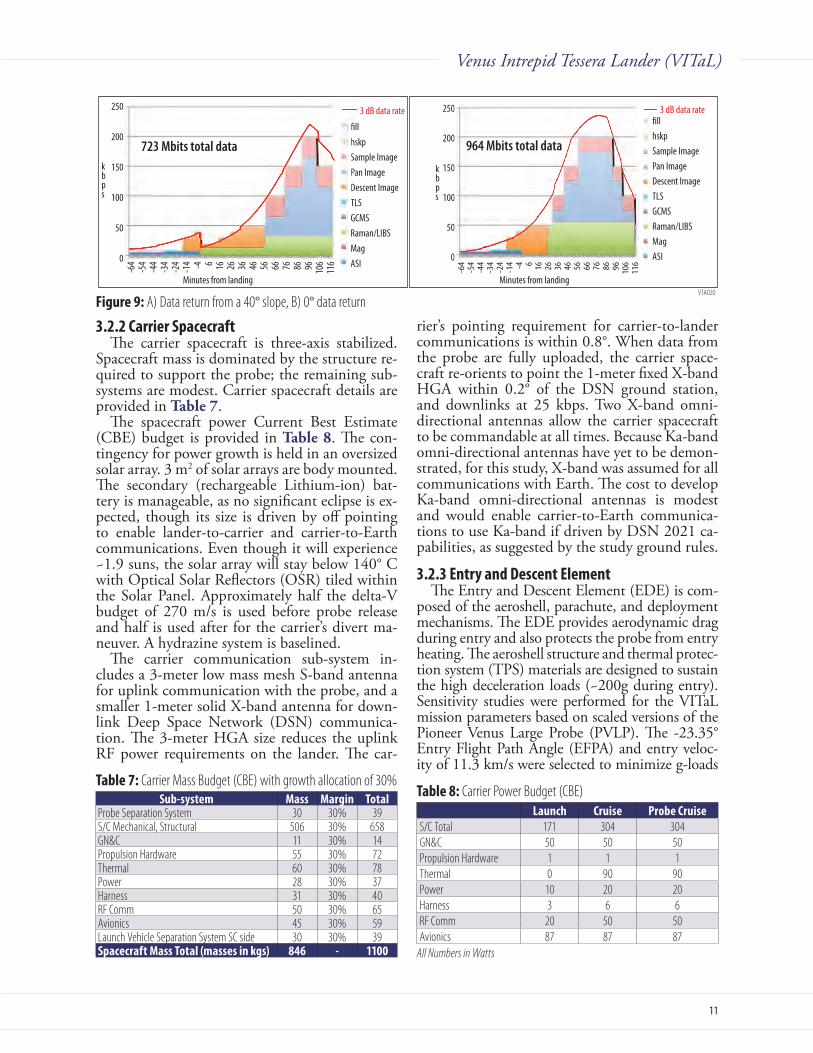
Since the communications system varies the data rate based on the signal strength to the car-rier, the amount of data returned depends on the angle with respect to the flyby spacecraft. Data uplink begins during descent. If the landing loca-tion is horizontal (0° inclined), the link returns 964 Mbits from atmospheric entry through 2 hours on the surface (Figure9b). If the lander is inclined 40° relative to the flyby spacecraft, an-tenna gain is reduced and 723 Mbits are returned (Figure9a). The data rate is autonomously ne-gotiated between the spacecraft and lander. The spacecraft monitors its decoder statistics and commands the data rate higher or lower to en-sure reliable communications. A similar scheme is currently implemented in the Electra equipment used between payloads on the surface of Mars and Martian orbiters. The lander buffers the data and sends the highest priority first. In the 40° case, the lander sends 75% of the panoramic images and 65% of the Raman/LIBS measurements. This drops to 356 Mbits or 37% of the total if the angle is 60°; the rate meets the minimum science requirements if this worst case slope is realized.
The lander is designed to operate for 2 hours after landing. At the end of the 2 hours, the land-er continues to send buffered images and replays high priority data for as long as it and the com-munication link lasts.
Figure 6: Descent and Panoramic ImageryVTA017
1 km
Descent Images
Approx.size ofpanoramiccameraimage FOV
VTA023
Accelerometers, gyro, WindsTemp, pressure
MagnetometerNMSTLS
Panoramic Image
Sample Image
Raman/LIBS
Minutes from Landing20 40 60 80 100 120
ASI
Figure 7: Surface Instrument Operations
VTA019
10 cm
0.86 meters at a distance of 2.5 meters from the Lander
Context Images
Figure 8: Raman/LIBS sample locations (yellow dots) and context images.
11
Venus Intrepid Tessera Lander (VITaL)
3.2.2 Carrier SpacecraftThe carrier spacecraft is three-axis stabilized.
Spacecraft mass is dominated by the structure re-quired to support the probe; the remaining sub-systems are modest. Carrier spacecraft details are provided in Table7.
The spacecraft power Current Best Estimate (CBE) budget is provided in Table8. The con-tingency for power growth is held in an oversized solar array. 3 m2 of solar arrays are body mounted. The secondary (rechargeable Lithium-ion) bat-tery is manageable, as no significant eclipse is ex-pected, though its size is driven by off pointing to enable lander-to-carrier and carrier-to-Earth communications. Even though it will experience ~1.9 suns, the solar array will stay below 140° C with Optical Solar Reflectors (OSR) tiled within the Solar Panel. Approximately half the delta-V budget of 270 m/s is used before probe release and half is used after for the carrier’s divert ma-neuver. A hydrazine system is baselined.
The carrier communication sub-system in-cludes a 3-meter low mass mesh S-band antenna for uplink communication with the probe, and a smaller 1-meter solid X-band antenna for down-link Deep Space Network (DSN) communica-tion. The 3-meter HGA size reduces the uplink RF power requirements on the lander. The car-
rier’s pointing requirement for carrier-to-lander communications is within 0.8°. When data from the probe are fully uploaded, the carrier space-craft re-orients to point the 1-meter fixed X-band HGA within 0.2° of the DSN ground station, and downlinks at 25 kbps. Two X-band omni-directional antennas allow the carrier spacecraft to be commandable at all times. Because Ka-band omni-directional antennas have yet to be demon-strated, for this study, X-band was assumed for all communications with Earth. The cost to develop Ka-band omni-directional antennas is modest and would enable carrier-to-Earth communica-tions to use Ka-band if driven by DSN 2021 ca-pabilities, as suggested by the study ground rules.
3.2.3 Entry and Descent ElementThe Entry and Descent Element (EDE) is com-
posed of the aeroshell, parachute, and deployment mechanisms. The EDE provides aerodynamic drag during entry and also protects the probe from entry heating. The aeroshell structure and thermal protec-tion system (TPS) materials are designed to sustain the high deceleration loads (~200g during entry). Sensitivity studies were performed for the VITaL mission parameters based on scaled versions of the Pioneer Venus Large Probe (PVLP). The -23.35° Entry Flight Path Angle (EFPA) and entry veloc-ity of 11.3 km/s were selected to minimize g-loads
VTA020
250
200
150
100
50
0
250
200
150
100
50
0
-64
-54
-44
-34
-24
-14 -4 6 16 26 36 46 56 66 76 86 96 106
116
�llhskpSample ImagePan ImageDescent ImageTLSGCMSRaman/LIBSMagASI
3 dB data rate
Minutes from landing Minutes from landing
kbps
kbps
723 Mbits total data
Minutes from Landing
kbps
3 dB data rate
723 Mbits total data
Minutes from Landing
kbps
3 dB data rate
723 Mbits total data
Minutes from Landing
kbps
3 dB data rate
964 Mbits total data
�llhskpSample ImagePan ImageDescent ImageTLSGCMSRaman/LIBSMagASI
3 dB data rate
Minutes from Landing
kbps
3 dB data rate
964 Mbits total data964 Mbits total data
-64
-54
-44
-34
-24
-14 -4 6 16 26 36 46 56 66 76 86 96 106
116
Figure 9: A) Data return from a 40° slope, B) 0° data return
Table 7: Carrier Mass Budget (CBE) with growth allocation of 30%Sub-system Mass Margin Total
Probe Separation System 30 30% 39S/C Mechanical, Structural 506 30% 658GN&C 11 30% 14Propulsion Hardware 55 30% 72Thermal 60 30% 78Power 28 30% 37Harness 31 30% 40RF Comm 50 30% 65Avionics 45 30% 59Launch Vehicle Separation System SC side 30 30% 39Spacecraft Mass Total (masses in kgs) 846 - 1100
Table 8: Carrier Power Budget (CBE)Launch Cruise probe Cruise
S/C Total 171 304 304GN&C 50 50 50Propulsion Hardware 1 1 1Thermal 0 90 90Power 10 20 20Harness 3 6 6RF Comm 20 50 50Avionics 87 87 87
All Numbers in Watts

12
Venus Intrepid Tessera Lander (VITaL)
(for ease of qualifying instruments and minimizing the structural mass of the aeroshell structure) and total heat load on the heat shield (for minimal TPS mass). After withstanding peak deceleration and heating, the parachute is deployed at 60 km, and the heat shield is separated from the lander using explosive separation bolts. Finally, the parachute and backshell are severed from the lander element, completing payload extraction. The monocoque 3.5 m diameter, 45° sphere cone aeroshell, shown in Figure 10, encapsulates the lander, supports launch and entry loads, and enables safe and reli-able atmospheric extraction of the lander. The heat shield is a scaled version of PVLP (which was 1.42-m diameter), while the back shell is similar in shape to Stardust. The structure is a 2-inch (5.08 cm) sandwich configuration with composite face sheets and aluminum honeycomb, providing mass savings over solid aluminum with sufficient structural in-tegrity up to 225 g. The total mass of the aeroshell, including structure, TPS, and parachutes, is 1050 kg (not including 30% margin). The heat shield’s mass is 717 kg, the back shell’s mass is 293 kg, and the parachute and mechanisms are 50 kg. The heat shield TPS consists of 0.93 inch (2.325 cm) total tape wrapped and chopped molded carbon phe-nolic (TWCP and CMCP) onto the honeycomb structure. CMCP and TWCP are the only mate-rials flight-qualified for the severe conditions of Venus entry. Peak stagnation heat flux (combined convective and radiative) on the heat shield is cal-culated to be 4.6 kW/cm2 (2021 launch). Both CMCP and TWCP were flown on the Pioneer-Venus and Galileo entry probes. Although heritage carbon phenolic (CP) production has been discon-tinued since the 1980s because the supplier ceased production of the rayon precursor, Ames Research Center (ARC) has a sufficient supply of the original CP precursor to fabricate a VITaL-sized probe and the associated test and evaluation billets. Even as-suming a PVLP-sized probe is launched to Venus
prior to VITaL, there is sufficient heritage rayon to construct the VITaL aeroshell (see Appendix).
Based on engineering estimates for the back-shell environment, Phenolic Impregnated Car-bon Ablator (PICA), a light weight ablator, can be used as the back shell TPS material. The PICA tiles are bonded to the structure using HT-424, with RTV-560 filled gaps, using the same manu-facturing techniques as Mars Science Laboratory (MSL). PICA has flown on Stardust and has been extensively evaluated and characterized as a heat shield material for MSL and was a candidate heat shield for Orion.
3.2.4 Lander
3.2.4.1 Lander Structure
Mechanical OverviewThe mechanical system is designed to safely
transport the instrument suite to a tessera region on the Venus surface. The mechanical design of the lander concept (Figure11) is driven by the two most challenging requirements: the high de-celeration loads expected during entry into the Venus atmosphere, and operational stability of the system after landing on an unknown terrain. Due to the uncertainty about terrain conditions at the landing site, proposed designs were select-ed to provide a high level of assurance of success even if the terrain is extremely uneven. It was as-sumed that the worst case scenario for this design
Figure 10: Aeroshell Dimensions (in mm)
177
2415.7
1113.6
176.9
757.1 659.1
3500
2512.8
VTA027
791
VTA021
Backshell
Heatshield
Backshell/Lander Truss
Landing RingCrush RingCrush Plate
Snubber
Parachute System
2.5 mDiameter
Figure 11: A) Ring lander, B) Ring lander in aeroshell
13
Venus Intrepid Tessera Lander (VITaL)
was landing on a 30° slope and with the high side of the lander striking a 1.3 m high block.
The Ring Lander design meets the instrument suite field-of-view (FOV) requirements for ground imaging during descent and landing, and for the Raman/LIBS instrument (Figure 3). The pan-oramic camera FOV requirement is met using the cupola structure at the top of the pressure vessel (Figure 3), and must include the Raman/LIBS sample location. The concept also meets the TLS and NMS instrument requirements for small vent openings by employing a 5 mm diameter vent opening with frangible ceramic solenoid actuated caps for atmospheric sampling.
The structural system design accommodates the high performance thermal control system, which includes isolation and insulation systems and phase change materials. The probe primary struc-ture is a hermetically-sealed pressure vessel to re-duce the transfer of thermal energy and prevent the influx of Venus atmosphere. The entire packaged lander is designed to fit into an aeroshell system (Figure 11b) and survive the 200 g loads expected during entry into the Venus atmosphere and the 83 g loads expected at impact on the Venus surface.
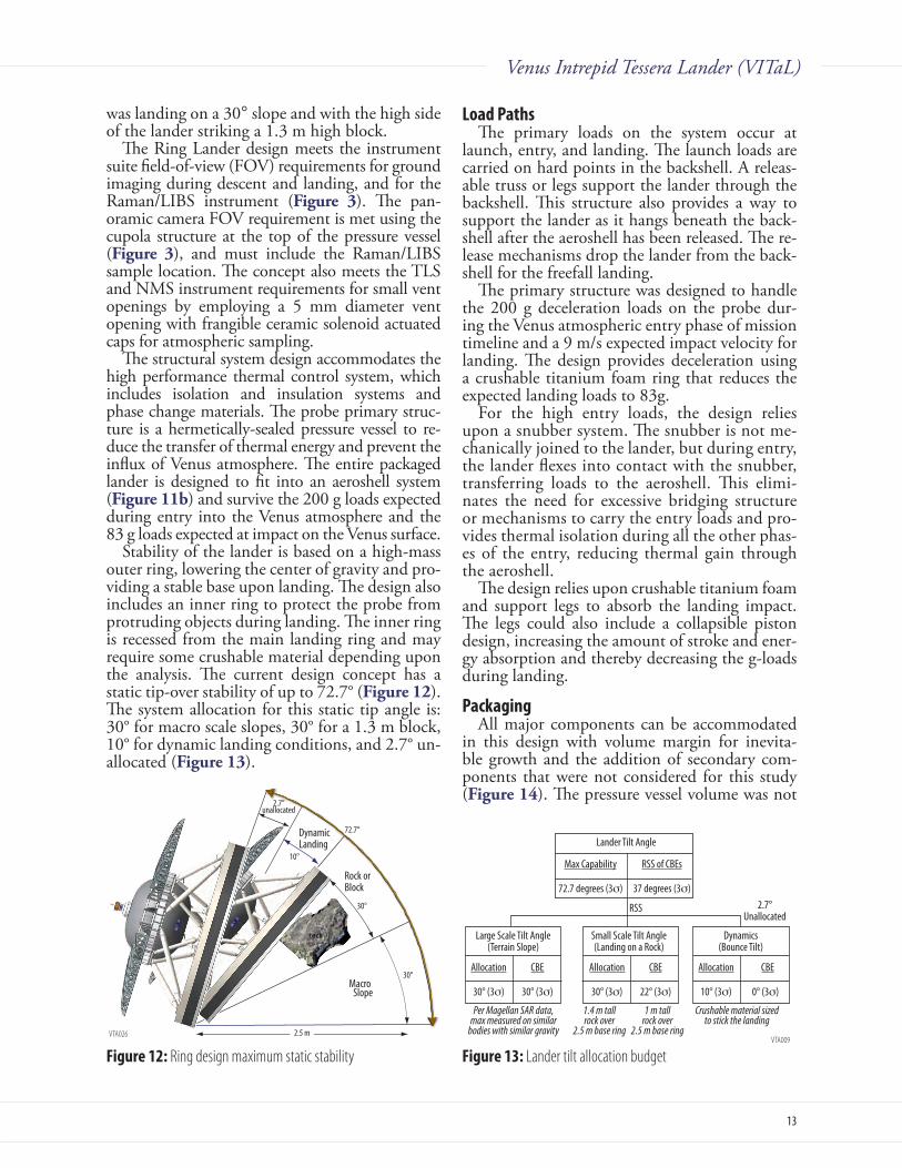
Stability of the lander is based on a high-mass outer ring, lowering the center of gravity and pro-viding a stable base upon landing. The design also includes an inner ring to protect the probe from protruding objects during landing. The inner ring is recessed from the main landing ring and may require some crushable material depending upon the analysis. The current design concept has a static tip-over stability of up to 72.7° (Figure12). The system allocation for this static tip angle is: 30° for macro scale slopes, 30° for a 1.3 m block, 10° for dynamic landing conditions, and 2.7° un-allocated (Figure13).
Load pathsThe primary loads on the system occur at
launch, entry, and landing. The launch loads are carried on hard points in the backshell. A releas-able truss or legs support the lander through the backshell. This structure also provides a way to support the lander as it hangs beneath the back-shell after the aeroshell has been released. The re-lease mechanisms drop the lander from the back-shell for the freefall landing.
The primary structure was designed to handle the 200 g deceleration loads on the probe dur-ing the Venus atmospheric entry phase of mission timeline and a 9 m/s expected impact velocity for landing. The design provides deceleration using a crushable titanium foam ring that reduces the expected landing loads to 83g.
For the high entry loads, the design relies upon a snubber system. The snubber is not me-chanically joined to the lander, but during entry, the lander flexes into contact with the snubber, transferring loads to the aeroshell. This elimi-nates the need for excessive bridging structure or mechanisms to carry the entry loads and pro-vides thermal isolation during all the other phas-es of the entry, reducing thermal gain through the aeroshell.
The design relies upon crushable titanium foam and support legs to absorb the landing impact. The legs could also include a collapsible piston design, increasing the amount of stroke and ener-gy absorption and thereby decreasing the g-loads during landing.
packagingAll major components can be accommodated
in this design with volume margin for inevita-ble growth and the addition of secondary com-ponents that were not considered for this study (Figure14). The pressure vessel volume was not
VTA026
10°
rock
30°
30°
72.7°
2.7°unallocated
DynamicLanding
Rock orBlock
MacroSlope
2.5 m
Figure 12: Ring design maximum static stability Figure 13: Lander tilt allocation budgetVTA009
Large Scale Tilt Angle(Terrain Slope)
Allocation CBE
30° (3σ) 30° (3σ)
Small Scale Tilt Angle(Landing on a Rock)
Allocation CBE
30° (3σ) 22° (3σ)
Dynamics(Bounce Tilt)
Allocation CBE
10° (3σ) 0° (3σ)
Per Magellan SAR data,max measured on similar
bodies with similar gravity
1.4 m tallrock over
2.5 m base ring
1 m tallrock over
2.5 m base ring
Crushable material sizedto stick the landing
Lander Tilt Angle
Max Capability RSS of CBEs
72.7 degrees (3σ) 37 degrees (3σ)
RSS 2.7°Unallocated

14
Venus Intrepid Tessera Lander (VITaL)
optimized, and some adjustment will likely be necessary as the design matures. Currently, the probe is well within the constraints of the aero-shell volume and there are no obvious issues for accommodating the payload.
Materials and Mass propertiesThe extremes of the environment and the high
g-loading drove the choice of a default material for the structural concept to titanium. Commer-cially available (high void fraction and vented) titanium foam is used for the crushable material. Preliminary sizing of the structural elements was performed to estimate sizing and to demonstrate concept feasibility. Detailed aerodynamic analysis of the drag plates was not performed, but the co-efficient of friction was estimated from assuming the lander had a disk profile (based on the drag plate shape) and calculating Reynold’s number to determine the terminal velocity. The complex dynamics of impact for the design is beyond the scope of this study but preliminary analysis indi-cates that the concept appears feasible. The drag plates shown in Figure 10 are 2.5 m in diameter. The aeroshell can accommodate drag plates up to 3.2 m in diameter, which will lower the impact velocity to 7 m/s.
3.2.4.2 Lander Mechanical Static and Dynamic Analysis
Analysis goalsThe Ring Lander has been analyzed to verify
that the design concept meets structural load and stability requirements during atmospheric entry and landing. Loads and stiffness requirements were both assumed and derived. The basic load cases are atmospheric entry, level landing, and landing on a macro and micro slope (40° inclined assumed). Table9 shows the load cases analyzed. The analysis used a landing velocity of 10 m/s, though for the actual lander, this was calculated as 9 m/s.
Landing Load Calculations – Ring LanderA crush pad area and depth were calculated
based on the amount of crush material needed to absorb the full kinetic energy of the lander upon contact with the surface. Figure 15 illus-trates how the crush pad area (as a percentage of the lander ring area) relates to crush pad required depth and the resulting equivalent g loading.
RF Comm Box
Raman/LIBS Laser TLS
Raman/LIBSand Imaging Assembly Mass Spectrometer
ASI
Panoramic Camera Assembly
MechanismControl Electronics
Transponder
Avionics
Raman/LIBSElectronics
Magnetometer
Batteries
VTA024
Table 9: Analysis planDesign goal Lander Details Notes
Fund. Freq (in aeroshell) >35 Hz Engineering judgmentAtmospheric Entry Load 200 g CalculatedLanding Velocity 10 m/s Calculated (CBE is 9 m/s)Level Landing Load 83 g DerivedNon-level landing load 43 g Derived Figure 15: Percent Area of Landing Pad Engaged
VTA002
0.50.45
0.40.35
0.30.25
0.20.15
0.10.05
00% 20% 40% 60% 80% 100%
180160140120100806040200
Land
ing Lo
ad (g
)
Percent Area of Landing Pad Crush Pad EngagedCrush Depth (m)G Load
Crus
h Pad
Dep
th (m
)
Crush Pad Area vs. Depth and Resulting G Load
Figure 14: Ring lander pressure vessel payload packaging

15
Venus Intrepid Tessera Lander (VITaL)
For the flat landing case, it was assumed that a crush pad covering 50% of the lander ring was engaged. For the non-level case, it was assumed that an area of 25% was engaged. This assumed that a load spreading plate under the crush pad helps distribute the load over a greater area of crushable material.
With the assumption that the crush pad ab-sorbs all the energy from the landing, it can also be inferred that the lander will remain upright as long as the system CG is low enough to be within the diameter of the landing ring. Calculations show that for the given CG location and lander ring diameter, the system is stable up to an angle of 72.7° versus the 60° requirement.
Analysis Models and ResultsThe Ring Lander was modeled in the MSC/
NASTRAN finite element analysis software and the design was analyzed to verify that primary structure meets ViTaL loading and stiffness goals (Table9). Figure16 shows the model used in the analyses. Only the primary and major secondary structural elements were analyzed for this effort. The pressure vessel and internal components are represented as simplified mass elements for the model.
Table10 shows how the design meets the anal-ysis goals. For the landing load analyses, the mate-rial properties and allowables used were degraded due to the Ovda Regio surface temperature.
The analysis efforts performed to date focused on the survivability of primary and major second-ary structural components. Preliminary analyses show the lander design meets the gross load and stiffness goals. Future analyses of the pressure vessel and internal components, including the Laser (due to the tight alignment requirements), are required.
3.2.4.3 Lander MechanismsEach VITaL mechanism (Figure17) comprises
a basic mechanical design with extensive flight heritage (TRL 6). The position resolutions, list-ed in Table11, represent easily attainable target values for these types of mechanisms. All drive mechanisms comprise a stepper motor coupled to an appropriately-sized planetary gear set (Ta-ble 11). A separate mechanisms control electron-ics box (shown in Figure14) is required to con-trol the actuators.
Figure 16: Ring lander finite element modelVTA003
Ring Lander
XY
Z
Table 10: Analysis ResultsDesign goal Requirement Ring
Fund. Freq (in aeroshell) > 35 Hz 35.2 HzAtmospheric Entry Load Stress Margin of Safety > 0 Min. MS= 0.11Level Landing Load Stress Margin of Safety > 0 Min. MS= 0.25Non-level landing load Stress Margin of Safety > 0 Min. MS= 0.71
Table 11: VITaL Mechanismspanoramic
cameraFilter
wheelRaman/
LiBS focusRaman/LiBS
pointingPositional resolution N/A N/A 5 µm 1.6 mm @ 2.5
metersRange of motion 0 - 270° 0 - 300° +/- 5mm 0 - 20°Output drive mechanism
Spur gear Spur gear Lead screw Spur gear
Positional feedback device
Switch or Encoder
Switch or Encoder
Encoder Encoder
VTA025
SapphireWindows (4)
Filter wheelmotor
Filter wheel
CCDcamera
Mirror/opticsRotation motor
Mirror/opticsRotation tube
Groundstructure
Leadscrew
Linearguide rods (2)
Focusmotor
Mirror
Pointingmotor
Raman/LIBSaxis of rotation
GroundStructure
Driven gearsegment
Panoramic Camera Mechanism Raman/LIBS Focus Mechanism Raman/LIBS Pointing Mechanism
Figure 17: Mechanisms for A) Panoramic camera and filter wheel, B) Raman/LIBS focusing, and C) Raman/LIBS and Context camera pointing

16
Venus Intrepid Tessera Lander (VITaL)
3.2.4.4 Lander ThermalThe Venus atmosphere presents a unique ther-
mal environment. The temperature of the atmo-sphere is 447° C, with a pressure of approximately 81 bar at the surface in the Ovda Regio (approxi-mately 2 km above mean planetary radius). The three-hour mission life includes a one-hour de-scent through the atmosphere, and 2 hours spent on the Venus surface. The operational tempera-ture limits of the avionics and instruments are assumed to be -20° C to 40° C, and their total heat dissipation is expected to be 239 W on the surface. The interior of the lander is pressurized at 1 bar, and natural convection is assumed to take place inside the pressure vessel.
The thermal strategy for this design concentrates the cooling directly at the electronics, and ther-mally isolates the two electronics decks from the rest of the lander. Phase change material (PCM) is embedded inside the decks to provide maximum conduction to the electronics, which are mounted on top of the decks. Lithium nitrate trihydrate (LNT) is selected as the PCM. LNT was flown on the Russian Venera landers, and minimizes mass and volume. Figure18 shows a graph of tempera-tures during the three-hour mission.
The outer layers of the thermal protection sys-tem, as shown in Figure19, include a layer of mi-croporous silica insulation (2.2 cm thick), followed by a 40-layer Multi-Layer Insulation (MLI) blan-ket. Microporous silica was selected for its high temperature tolerance (up to 1000° C) and low thermal conductivity (0.035 W/mK). The MLI blanket design is similar to that used on the Pio-neer Venus large probe.
There are multiple heat leaks into the pressure vessel, as quantified in Figure20. Seven sapphire windows are required for conducting science ob-servations from within the lander. Each window is double-paned, with a small air gap between for ther-mal insulation. There are two small intake tubes for NMS and TLS to collect atmospheric gas samples during descent. An umbilical runs from the outside of the lander, through the insulation, and connects to the carrier, contributing additional heat input. To increase thermal isolation of the decks, the in-ternal support structure is designed using flexures with small cross-sectional area to minimize the heat flow from the pressure vessel wall to the decks.
The Systems Improved Numerical Differenc-ing Analyzer (SINDA) analysis performed for this model assumes the heat is spread evenly over the deck. In later iterations of the design, it may be necessary to compensate for possible hot spots on the deck; if this occurs, the aluminum deck plate could be made thicker, to spread the heat more evenly, and/or additional heat spreading devices may be used. It may also be necessary to place an amount of PCM locally at the cameras, which are close to the high-temperature windows. Model predictions currently show that 50 kg of PCM (13 kg of which is packaging) are needed to keep the electronics at or below 35° C for the duration of the three-hour science mission (Figure18).
3.2.4.5 Lander OpticsVITaL includes four optical instruments: De-
scent camera, Panoramic camera, Raman/LIBS context imager, and Raman/LIBS spectrometer.
Figure 18: Lander Temp During MissionVTA031
ApproachVenus
AtmosphericEntry Begins
Land onVenus Temperature
Limits Reached(2hrs 14 min)
End of Nominal Mission(2hrs on surface)
Mission Time Elapsed [minutes]
Temper
ature (
C)
50
40
30
20
10
0
-10
-20
Temperature of Avionics & Instruments During Mission
0 50 100 150 200 250 300
Figure 19: Thermal sketch of landerVTA005
Note: window size and locations NOT drawn to scale here.
MicroporousSilica Insulation
(2.2 cm thick)
MLI Blanket(2.54 cm thick)
Outer Window PaneInner Window Pane
Raman/LIBS Camera(3 cm diam)
DescentImager
(2.4 cm diam)
Raman/LIBBTelescope
(6.5 cm diam)
Two tubesfor atmosphericsampling (massspec. and TLS)
Cupola with four windows(double-paned, 4.5 x 4 cm each)
InnerStrut
OuterStrut
Main Support Ring
Inner Shell(attach MLI)
Pressure Vessel (PV)
Outer Shell
447°C
366°C
CO2 VenusAtmosphere
90°C N2 @ 1 atm
30°C Avionics
Avionics 2
Deck 1 (PCM inside)
Deck 2 (PCM inside)Umbilicals
VTA004
PV and MLI(inner layer)
ElephantStand
Windows
Umbilical
Cupola PV
Cabin Air
Decks andAvionics
191°C
181°C
296°C30°C
90°C
317°C
32W
1060W
967W52W
9W
421W
64W
87W
230W
Radiation Convection Conduction
Note: Values above represent the TOTAL heat �ow into both decks. (Each deck receives 930W; total �owing into both decks in 1860W)
InternalDissipation
239W
Figure 20: Diagram of heat leaks

17
Venus Intrepid Tessera Lander (VITaL)
Descent iR CameraThe Descent Camera (Table 12) images the
Venus surface during descent. The 1.0 µm wave-length minimizes scattering at shorter wavelengths and absorption at longer wavelengths [Crisp, 2000]. The instrument aperture diameter is 8 mm (the window is 24 mm). The aperture is set at the back surface of the sapphire window to minimize thermal window size (Figure21). Optical com-ponents are minimized to reduce mass while still maintaining image quality and the RMS spot size within one pixel across the full FOV.
panoramic CameraThe Panoramic Camera (Table13): 1) surveys
the local terrain, and 2) provides context imag-ing for the narrow focused Raman/LIBS context camera. The Panoramic camera covers a FOV from 25° below to 10° above the lander’s hori-zon, and ±30° in azimuth (Figure 22). During the mission, a mirror is rotated to four azimuth angles (0°, 90°, 180°, and 270°) about the lens axis. The panoramic camera takes images at l = 550, 650, 750, 850, 1000 nm, with a bandwidth Full Width Half Maximum (FWHM) of 20-30 nm. It also takes an image with a clear aperture, using the CCD’s natural responsivity curve. Be-
cause the intensity of the beam from a clear ap-erture is much higher than that passed through bandpass filters, a neutral density filter is added to get the intensity to the same order of magnitude. The defocus blur at 2.5 m is less than a pixel.
Raman/LiBS Context imagerThe Raman/LIBS Context Imager (Table14) is
designed to monitor the laser spot position with respect to the scene using a single 550-700 nm fil-ter. To minimize data volume, the laser spot (250 µm) is slightly under sampled (2.48 versus 3 pixels/laser spot) by the Context Imager. The wavelength range for this imager is limited to the CCD’s spec-tral response, and the 532 nm laser spot may lo-cally saturate CCD pixels. Even though the 532 nm laser spot is weaker than the 1064 nm laser spot, it is still strong versus the background noise. Camera optics are shown in the Appendix.
Raman/LiBS SpectrometerThe Raman/LIBS spectrometer (Table 15) is
used for in situ mineralogy and elemental mea-surements. A Q-switch pulse laser with dual wave-
Table 12: Descent Camera SpecificationsFOV ±20°Spatial resolution 0.04°Wavelength 1.0µm with 20nm bandwidthS/N >100 with 1ms exposure timeDetector 1024×1024 with 13µm pixel sizeSize 5cm×5cm×7.5cm (exclude window and detector)Mass ~100g (lenses only)Exposure time 1ms
VTA006
Sapphire Window
10.00 Millimeters
DetectorArray
Table 13: Panoramic Camera SpecificationsFOV 35° in elevation and 60° in azimuth (both full FOV) Spatial resolution 0.25cm at 2.5mWavelength 550nm – 1000nmS/N >1500 with 100ms exposure timeDetector 2k×2k with 8.5µm pixel size (1338×2048 pixels imaged)Instrument Size 5cm×5cm×11cm (lenses and mirror only)Mass ~150g (lenses and mirror only)
VTA007
Spectral �lter
Aperture stop
10.00 Millimeters
CCDChip
Sapphirewindow
Figure 21: Descent Camera Optics
Figure 22: Panoramic Camera Optics
Table 14: Raman/LIBS Context Imager Specifications. FOV 20cm×20cmSpatial resolution 0.1mmWavelength 550nm – 700nmS/N >2500 with 30ms exposure timeDetector 2k×2k with 8.5µm pixel sizeSize 5cm×5cm×20cm (lenses only)Mass ~130g (lenses only)
Table 15: Raman/LIBS Spectrometer SpecificationsFOV ±0.0033°Spectral resolution >2500Wavelength 530nm – 700nmDetector 3000×96 with 10µm pixel sizeSize 26cm×21cm×10cm
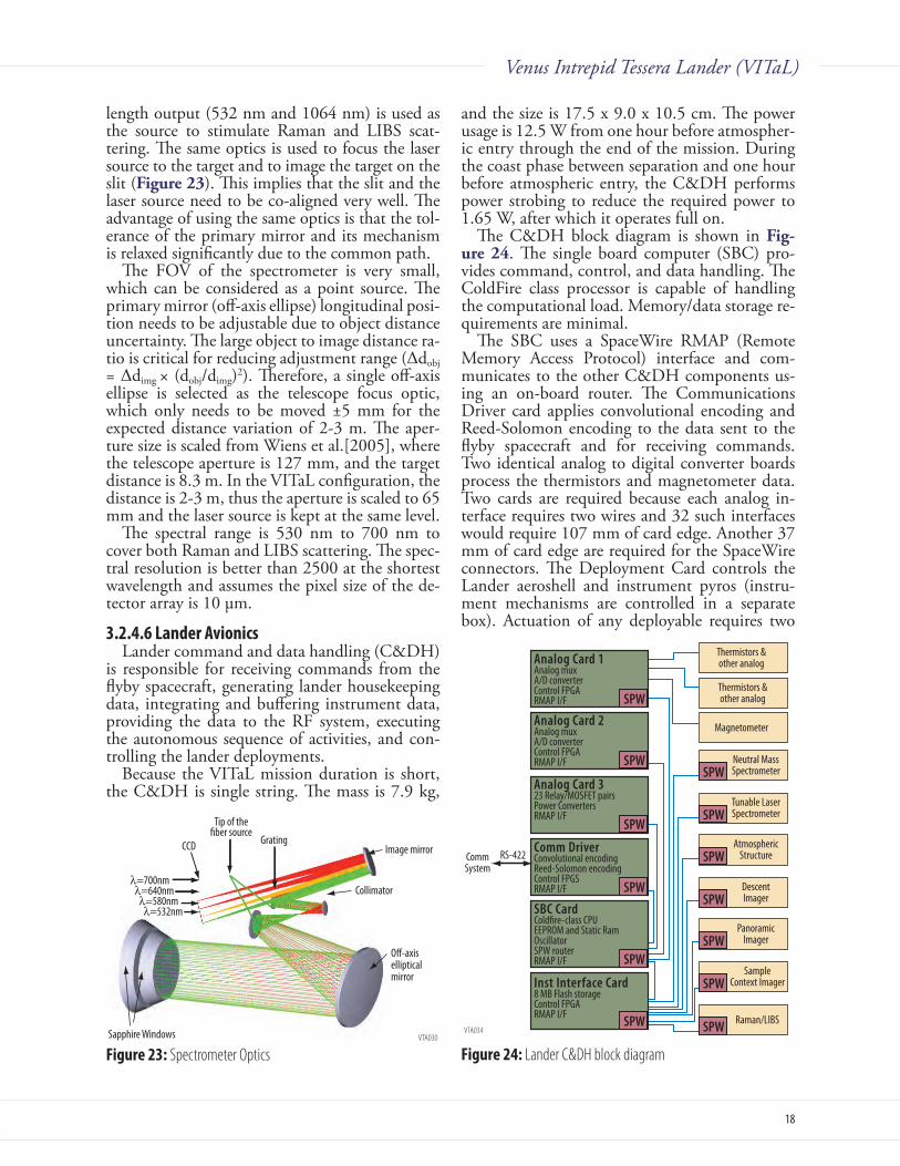
18
Venus Intrepid Tessera Lander (VITaL)
length output (532 nm and 1064 nm) is used as the source to stimulate Raman and LIBS scat-tering. The same optics is used to focus the laser source to the target and to image the target on the slit (Figure23). This implies that the slit and the laser source need to be co-aligned very well. The advantage of using the same optics is that the tol-erance of the primary mirror and its mechanism is relaxed significantly due to the common path.
The FOV of the spectrometer is very small, which can be considered as a point source. The primary mirror (off-axis ellipse) longitudinal posi-tion needs to be adjustable due to object distance uncertainty. The large object to image distance ra-tio is critical for reducing adjustment range (Δdobj = Δdimg
× (dobj/dimg)2). Therefore, a single off-axis ellipse is selected as the telescope focus optic, which only needs to be moved ±5 mm for the expected distance variation of 2-3 m. The aper-ture size is scaled from Wiens et al.[2005], where the telescope aperture is 127 mm, and the target distance is 8.3 m. In the VITaL configuration, the distance is 2-3 m, thus the aperture is scaled to 65 mm and the laser source is kept at the same level.
The spectral range is 530 nm to 700 nm to cover both Raman and LIBS scattering. The spec-tral resolution is better than 2500 at the shortest wavelength and assumes the pixel size of the de-tector array is 10 µm.
3.2.4.6 Lander AvionicsLander command and data handling (C&DH)
is responsible for receiving commands from the flyby spacecraft, generating lander housekeeping data, integrating and buffering instrument data, providing the data to the RF system, executing the autonomous sequence of activities, and con-trolling the lander deployments.
Because the VITaL mission duration is short, the C&DH is single string. The mass is 7.9 kg,
and the size is 17.5 x 9.0 x 10.5 cm. The power usage is 12.5 W from one hour before atmospher-ic entry through the end of the mission. During the coast phase between separation and one hour before atmospheric entry, the C&DH performs power strobing to reduce the required power to 1.65 W, after which it operates full on.
The C&DH block diagram is shown in Fig-ure 24. The single board computer (SBC) pro-vides command, control, and data handling. The ColdFire class processor is capable of handling the computational load. Memory/data storage re-quirements are minimal.
The SBC uses a SpaceWire RMAP (Remote Memory Access Protocol) interface and com-municates to the other C&DH components us-ing an on-board router. The Communications Driver card applies convolutional encoding and Reed-Solomon encoding to the data sent to the flyby spacecraft and for receiving commands. Two identical analog to digital converter boards process the thermistors and magnetometer data. Two cards are required because each analog in-terface requires two wires and 32 such interfaces would require 107 mm of card edge. Another 37 mm of card edge are required for the SpaceWire connectors. The Deployment Card controls the Lander aeroshell and instrument pyros (instru-ment mechanisms are controlled in a separate box). Actuation of any deployable requires two
Figure 23: Spectrometer OpticsVTA030
CCD
Tip of the�ber source
Sapphire Windows
Collimator
O�-axisellipticalmirror
Image mirror
λ=700nm λ=640nm
λ=580nm λ=532nm
Grating
VTA034
Analog Card 1Analog muxA/D converterControl FPGARMAP I/F SPW
SBC CardCold�re-class CPUEEPROM and Static RamOscillatorSPW routerRMAP I/F SPW
Analog Card 2Analog muxA/D converterControl FPGARMAP I/F SPW
Analog Card 323 Relay/MOSFET pairsPower ConvertersRMAP I/F
SPW
Comm DriverConvolutional encodingReed-Solomon encodingControl FPGSRMAP I/F SPW
Inst Interface Card8 MB Flash storageControl FPGARMAP I/F SPW
Thermistors &other analog
Thermistors &other analog
Magnetometer
Neutral MassSpectrometerSPW
AtmosphericStructureSPW
DescentImagerSPW
PanoramicImagerSPW
SampleContext ImagerSPW
Raman/LIBSSPW
Tunable LaserSpectrometerSPW
CommSystem
RS-422
Figure 24: Lander C&DH block diagram
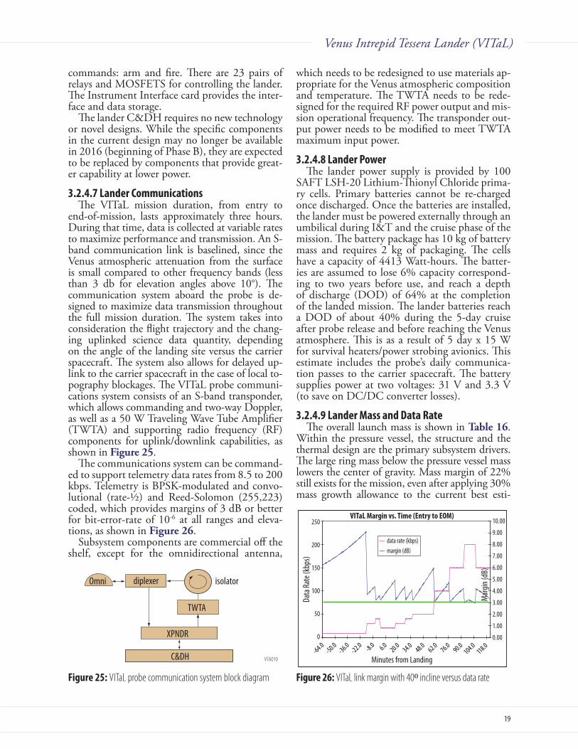
19
Venus Intrepid Tessera Lander (VITaL)
commands: arm and fire. There are 23 pairs of relays and MOSFETS for controlling the lander. The Instrument Interface card provides the inter-face and data storage.
The lander C&DH requires no new technology or novel designs. While the specific components in the current design may no longer be available in 2016 (beginning of Phase B), they are expected to be replaced by components that provide great-er capability at lower power.
3.2.4.7 Lander CommunicationsThe VITaL mission duration, from entry to
end-of-mission, lasts approximately three hours. During that time, data is collected at variable rates to maximize performance and transmission. An S-band communication link is baselined, since the Venus atmospheric attenuation from the surface is small compared to other frequency bands (less than 3 db for elevation angles above 10°). The communication system aboard the probe is de-signed to maximize data transmission throughout the full mission duration. The system takes into consideration the flight trajectory and the chang-ing uplinked science data quantity, depending on the angle of the landing site versus the carrier spacecraft. The system also allows for delayed up-link to the carrier spacecraft in the case of local to-pography blockages. The VITaL probe communi-cations system consists of an S-band transponder, which allows commanding and two-way Doppler, as well as a 50 W Traveling Wave Tube Amplifier (TWTA) and supporting radio frequency (RF) components for uplink/downlink capabilities, as shown in Figure25.
The communications system can be command-ed to support telemetry data rates from 8.5 to 200 kbps. Telemetry is BPSK-modulated and convo-lutional (rate-½) and Reed-Solomon (255,223) coded, which provides margins of 3 dB or better for bit-error-rate of 10-6 at all ranges and eleva-tions, as shown in Figure26.
Subsystem components are commercial off the shelf, except for the omnidirectional antenna,
which needs to be redesigned to use materials ap-propriate for the Venus atmospheric composition and temperature. The TWTA needs to be rede-signed for the required RF power output and mis-sion operational frequency. The transponder out-put power needs to be modified to meet TWTA maximum input power.
3.2.4.8 Lander powerThe lander power supply is provided by 100
SAFT LSH-20 Lithium-Thionyl Chloride prima-ry cells. Primary batteries cannot be re-charged once discharged. Once the batteries are installed, the lander must be powered externally through an umbilical during I&T and the cruise phase of the mission. The battery package has 10 kg of battery mass and requires 2 kg of packaging. The cells have a capacity of 4413 Watt-hours. The batter-ies are assumed to lose 6% capacity correspond-ing to two years before use, and reach a depth of discharge (DOD) of 64% at the completion of the landed mission. The lander batteries reach a DOD of about 40% during the 5-day cruise after probe release and before reaching the Venus atmosphere. This is as a result of 5 day x 15 W for survival heaters/power strobing avionics. This estimate includes the probe’s daily communica-tion passes to the carrier spacecraft. The battery supplies power at two voltages: 31 V and 3.3 V (to save on DC/DC converter losses).
3.2.4.9 Lander Mass and Data RateThe overall launch mass is shown in Table16.
Within the pressure vessel, the structure and the thermal design are the primary subsystem drivers. The large ring mass below the pressure vessel mass lowers the center of gravity. Mass margin of 22% still exists for the mission, even after applying 30% mass growth allowance to the current best esti-
VTA010
Omni
XPNDR
TWTA
C&DH
diplexer isolator
Figure 25: VITaL probe communication system block diagramVTA013
VITaL Margin vs. Time (Entry to EOM)
Minutes from Landing
Data
Rate
(kbp
s)
10.00
9.00
8.00
7.00
6.00
5.00
4.00
3.00
2.00
1.00
0.00
-64.0 -50.0
-36.0 -22.0
-8.0 6.0
20.0 34.0
48.0 62.0
76.0 90.0
104.0 118.0
250
200
150
100
50
0
Mar
gin (d
B)
data rate (kbps)margin (dB)
Figure 26: VITaL link margin with 400 incline versus data rate
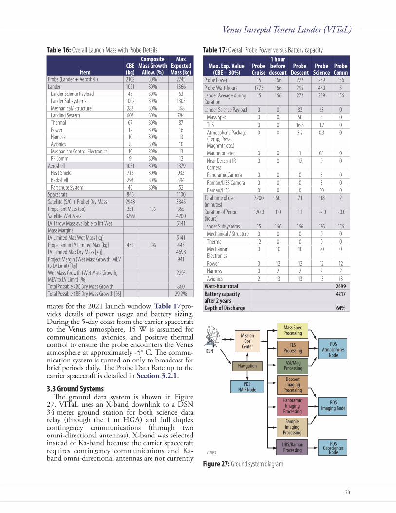
20
Venus Intrepid Tessera Lander (VITaL)
mates for the 2021 launch window. Table17pro-vides details of power usage and battery sizing. During the 5-day coast from the carrier spacecraft to the Venus atmosphere, 15 W is assumed for communications, avionics, and positive thermal control to ensure the probe encounters the Venus atmosphere at approximately -5° C. The commu-nication system is turned on only to broadcast for brief periods daily. The Probe Data Rate up to the carrier spacecraft is detailed in Section3 2 1.
3.3 ground SystemsThe ground data system is shown in Figure
27. VITaL uses an X-band downlink to a DSN 34-meter ground station for both science data relay (through the 1 m HGA) and full duplex contingency communications (through two omni-directional antennas). X-band was selected instead of Ka-band because the carrier spacecraft requires contingency communications and Ka-band omni-directional antennas are not currently
Table 16: Overall Launch Mass with Probe Details
itemCBE (kg)
Composite Mass growth
Allow. (%)
Max Expected Mass (kg)
Probe (Lander + Aeroshell) 2102 30% 2745Lander 1051 30% 1366
Lander Science Payload 48 30% 63Lander Subsystems 1002 30% 1303Mechanical/ Structure 283 30% 368Landing System 603 30% 784Thermal 67 30% 87Power 12 30% 16Harness 10 30% 13Avionics 8 30% 10Mechanism Control Electronics 10 30% 13RF Comm 9 30% 12
Aeroshell 1051 30% 1379Heat Shield 718 30% 933Backshell 293 30% 394Parachute System 40 30% 52
Spacecraft 846 1100Satellite (S/C + Probe) Dry Mass 2948 3845Propellant Mass (3σ) 351 1% 355Satellite Wet Mass 3299 4200LV Throw Mass available to lift Wet 5141Mass Margins LV Limited Max Wet Mass [kg] 5141Propellant in LV Limited Max [kg] 430 3% 443LV Limited Max Dry Mass [kg] 4698Project Margin (Wet Mass Growth, MEV to LV Limit) [kg]
941
Wet Mass Growth (Wet Mass Growth, MEV to LV Limit) [%]
22%
Total Possible CBE Dry Mass Growth 860Total Possible CBE Dry Mass Growth [%] 29.2%
Table 17: Overall Probe Power versus Battery capacity.
Max. Exp. value (CBE + 30%)
probe Cruise
1 hour before
descentprobe
Descentprobe
Scienceprobe Comm
Probe Power 15 166 272 239 156Probe Watt-hours 1773 166 295 460 5Lander Average during Duration
15 166 272 239 156
Lander Science Payload 0 0 83 63 0Mass Spec 0 0 50 5 0TLS 0 0 16.8 1.7 0Atmospheric Package (Temp, Press, Magnmtr, etc.)
0 0 3.2 0.3 0
Magnetometer 0 0 1 0.1 0Near Descent IR Camera
0 0 12 0 0
Panoramic Camera 0 0 0 3 0Raman/LIBS Camera 0 0 0 3 0Raman/LIBS 0 0 0 50 0
Total time of use (minutes)
7200 60 71 118 2
Duration of Period (hours)
120.0 1.0 1.1 ~2.0 ~0.0
Lander Subsystems 15 166 166 176 156Mechanical / Structure 0 0 0 0 0Thermal 12 0 0 0 0Mechanism Electronics
0 10 10 20 0
Power 0 12 12 12 12Harness 0 2 2 2 2Avionics 2 13 13 13 13
Watt-hour total 2699Battery capacity after 2 years
4217
Depth of Discharge 64%
VTA033
MissionOps
Center
Navigation
PDSNAIF Node
Mass SpecProcessing
TLSProcessing
ASI/MagProcessing
DescentImaging
Processing
PDSAtmospheres
Node
PDSImaging Node
PDSGeosciences
Node
PanoramicImaging
Processing
SampleImaging
Processing
LIBS/RamanProcessing
DSN
Figure 27: Ground system diagram

21
Venus Intrepid Tessera Lander (VITaL)
VTA035
TRADES Venus Intrepid Tessera Lander (VITaL), RMA + Study Complete Trade TreeFlt
Dyn
Trad
esDa
ta Li
nk Tr
ades
Land
ing Tr
ades
Scien
ce Tr
ades
Land
er Tr
ades
--- --- --- 2021 < Pro rammatics consideration KEY
--- 2023 X Bad for programmatics Traded item
--- --- Type I X C3 too high Option baselined
--- Type II < Best for Ovda region Further Subsystem Trades conducted (not itemized here)
--- --- "Heritage" 19 degree FPA X Suboptimal Option not baselined but worthy of further analysis
--- Steeper FPA < Best for Ovda region Option Rejected based on research and/or analysis
--- --- DTE X Negative link marg Osni ption Rejected based on engineering judgement or 1st order analysis
--- --- Brake & direct < Lowest cost, meets reqs
--- Parabolic flyby X Low elevation angles; rapid range increase
--- Hi ellipt orbit X Re uires more ro ellant than fl b with no added benefit
--- Low circ orbit X Too much propellant, no science benefit
--- Hi-Alt Balloon X Complexity; difficult to point
--- Airplane X Requires too much power, mass; low TRL
------------ Outriggers X Heavier, may require mechanisms
--- Landing spears ("porcupine") X Hard to model, verify
---Adaptive (crushable) landing rings
--- Traded Crushable Material: Honeycomb (difficult assy), Ti Foam, Airbag (env. issues)
--------- Thrusters X Venus env, low TRL, difficult verif.
--- Aerodynamic X
noitazilibats cipocsoryG------ X Complicated, heavy, hard to model
--- Actuated self righting X Requires more mass, mechanisms
--- Gravity auto self righting < Complicated design
llird "pihsgalF"------------ X Higher mass, pwr, data vol., measurement duration
--- Rasp on lander foot X Higher mass, pwr, data vol., measurement duration
------Autofocus
--- Traded Laser size, Telescope size, Distance to target vs. S/N
< Config optimized
--- No focus X OK for Raman, but LIBS would be less sensitive
--- --- 2 or 4 total X Inadequate, obstructions
--- 7 total < Windows: 1 for Descent Cam on bottom, 4 Pan Cams on top (240 deg FOV!), 1 Raman/Libs, 1 Sample Site Cam)
--------- Rotate pressure vessel X Venus environment mechanism
--- Internal rotation w/ cupola X Complicated, heavy
dnG morf lortnoc xelpud lluf w gnitniop evitcA------
--- Springs activated one time pan
rorrim dexif seerged 063------ X Bad resolution
--- Fixed limited to 240 deg < Lowest cost, meets requirements
stnemeriuqer steem ,tsoc tsewoL<---------
--- X Mass, added mechanism
--- X Mass, added mechanism
--- --- X Not necessary
stnemeriuqer steeM<---
--- --- X Very low TRL, a possible consideration for future missions
------ ISRU dry ice (atm CO2) X Very low TRL
--- Li Nitrate Trihydrate < Least mass/volume
--- Paraffin Wax X Less efficient (even if benignnon toxic)
<------ Allows variable transmission rates, with prioritized data
--- X Resources are available to enhance capabilities by commanding (minor impact)
--- X Low TRL, too expensive
--- --- X ASRGs are not designed for Venus surface (sink temperature!)
--- X Lower energy/mass density ratio
ssam tsewoL<---
---C&DH
< Lowest power
--- --- X Uncertainty in landing position
--- X Requires Venus grade hi-temp mechanisms
elgna yna skrow ,tsoc tsewoL<---
Actuated HGA
Omni antennas
Phase change material
Trades on Pwr: Static vs dynamic RAM; 5VDC vs 3.3VDC; Power on vs strobing; 1553 vs. spacewire
ASRG
Secondary batteries
Li-SOCl2 primary batteries
Panning
Carrier S/C roll before probe release
Turntable
Probe spins up autonomously
On surface > 2 hrs
360 deg pan
Fixed FOV
Probe Spin Up
Lander Autonomy
Power
RF Comm
On surface 2 hours
Hi temperature electronics
Commandble, limited autonomy
Sequencer controlled
Not commandable, fully intelligent autonomy
Shaped antennas
Number of Windows
Venu
s In
trepi
d Te
sser
a Ex
plor
er (V
ITaL)
Land
er c
onfig
urat
ion
Scien
ce A
ccom
mod
atio
n
Sample Charact. Method
Lifetime
Lander Thermal Control
Data
Lin
k
Panoramic Camera FOV
Launch Date
Orbit
Flt Path Angle
Flyby S/C
Fligh
t Dyn
amics
Land
on
Tess
era
Active control of landing site (ALHAT)
Random landing site w/ attitude control
Ingest sample, XRD/XRF
Measure remotely, Raman/LIBS
Land on max (large scale)40 deg. slope
Landing Resilience
Land anywhere
Meet Requirements as defined inTilt Angle Error Budget withincost constraints (heritage design,easty test and model).
<
Too complex, low TRL, difficultverif, Lidar imaging
Figure 28: VITaL trade tree

22
Venus Intrepid Tessera Lander (VITaL)
available. The lack of Ka-band omni-directional antennas, and the low volume of science data (less than 1 Gbit), does not require the performance of Ka-band, resulting in lower cost and mass. If Ka-band is mandated for all science data downlink, VITaL could implement it with a modest increase in the cost and complexity of the carrier space-craft communications system.
VITaL does not require the use of the 70-me-ter antennas and uses only one ground station at a time, with the exception of infrequent Delta Dop-pler One-way Ranging support to refine the navi-gation. The Navigation function is responsible for determining the trajectory of the spacecraft, plan-ning maneuvers, and supporting lander release.
The Mission Operations Center (MOC) is responsible for carrier spacecraft operations and monitoring autonomous lander operations. Dur-ing lander operations, the carrier spacecraft re-ceives telemetry data from the lander via the S-band High Gain Antenna, and relays low rate status data to Earth using an X-band omni-direc-tional antenna. The one-way light time to Earth is about 12 minutes. After lander operations have ended, the carrier spacecraft points the 1-meter X-band HGA to Earth and sends the data at 25 kbps. The total science data volume is between 356 Mbits and 964 Mbits. Once the data is reli-ably returned to Earth, the VITaL mission ends – about 9 months after launch.
The instrument teams process the science data and deliver the science data products to the Plan-etary Data System within 6 months of the end of mission operations.
3.4 Key TradesFor the VITaL study, more emphasis was
placed on in-depth “real” engineering in selected areas of interest than would have been in a typi-cal rapid mission architecture study. Accordingly, in addition to the usual mission and system level trades completed (orbit and flight dynamics, landing site selection, science requirements and instrumentation, mission lifetime and thermal architecture, power source, degree of lander au-tonomy, communication architecture, and oper-ations), a significant number of trades for VITaL were also performed at the lower subsystem and discipline levels (Figure 28). The most exten-sive subsystem trades were associated with the landing subsystem architecture, using resilience versus communications and instrument perfor-mance as the figures of merit. The viable candi-date options were then further refined by trades within the following disciplines:
A. Mechanical design: Concepts were ranked us-ing the results of Finite Element analyses as the primary figure of merit. Lower level trades conducted to optimize critical components, such as the crushable material (metal foam) used in the landing rings.
B. Optics: Trading refractive vs. reflective; win-dows layout, size, and material; focusing ap-proach. The optics trades were supported by FOV, geometric optics, signal to noise, and ray trace analyses as required, providing the figures of merit.
C. Avionics: Trades on operating voltage, data network architecture, and power strobing were made using power consumption and computing performance as figures of merit.
3.4.1 Lander Design TradeThe Cage Lander, developed as an alternative
to the Ring Lander, has a rotatable pressure vessel protected on all sides by structure (Figure 29). This design has the advantage of operating even if it flips upside down. However, because struc-tural members (the cage) fully envelope the pres-sure vessel and because the pressure vessel will rotate within the cage, panoramic camera, omni antenna, and Raman/LIBS instrument FOVs are potentially affected. Measures may be taken to ensure adequate science can be returned (e.g., adding actuators to move the cage structure, post-landing, away from the “up” side of the lander to ensure adequate instrument and omni FOVs).
Dynamically, the cage design need not fully absorb the impact energy because there is no lost
VTA028
OmniAntenna
Cage
PressureVessel
DragPlate
VTA032
OmniAntenna
Crushable Material
PressureVessel
Figure 29: Cage Lander design A, without crushable material, A) Iso view; B) Instrument FOV
Figure 30: Cage Lander design B, with crushable material, A) Iso view; B) Instrument FOV

23
Venus Intrepid Tessera Lander (VITaL)
capability if it bounces and flips. This allows for a less rigid structural design that may include some amount of crushable material. A second version of the cage design has been generated that has an annulus region of crushable material above and below the pressure vessel (Figure30). Using crushable material rather than the cage to protect the pressure vessel enables the omni antenna to function without the heavy communication up-link penalty of the cage (which acts as a reflector for the long wavelength S-Band). Figure29b and Figure 30b illustrate the instruments’ FOV for each cage lander concept, although further study is needed to fully compare each cage design. Both cage designs take advantage of the pressure ves-sel’s ability to rotate to an “omni-up” pose within the cage. This controlled rotation is accomplished by incorporating a motorized rotating counter-weight within the pressure vessel that will alter the vessel’s center of gravity, causing the pressure vessel to rotate. Both cage landers also have the advan-tage of being lighter than the Ring Lander, pos-sibly allowing a smaller launch vehicle. Table 18 provides an assessment of the two alternative cage designs versus the baseline Ring Lander. The Ring Lander was chosen as a baseline due to its lower complexity and cost, but there are advantages to the other designs. A figure of merit value of 5 is essentially high performance and off-the-shelf, while a 1 means that characteristic is a significant risk or requires major development.
3.4.2 Crushable Material TradeCrushable material is required to enable the
lander to “stick” the landing (not bounce). If the lander bounces, it may tip the lander over, even on a static stable landing site that would have been safe. Using crushable material reduces the g load on the lander at impact by plastically de-forming or “crushing” to absorb the kinetic en-ergy of landing. Crushable material can be foam, honeycomb, or custom structural shape. Most balloon-like materials (such as air bags used for landings on other planets) would either present a complex qualification challenge or will not sur-vive in the Venus atmosphere. Propulsion systems are not easily achieved due to Venus surface tem-peratures and pressures.
Ideal crushable materials have: 1) a high void fraction (so the usable crushable stroke is maxi-mized), 2) properties that don’t degrade at Venus surface pressure and temperature, 3) isotropic properties (in case of side impacts), 4) near linear crushing under a constant pressure, and 5) pre-dictable analytical and empirical performance.
The Venera Landers had a hollow toroidal crush pad and shock absorbers for landing. Detailed description of this system is not provided in the available literature. This approach is analytically complex and difficult to build and test. The Venus Flagship Mission Report [Bullock, 2009] suggest-ed the crushable material would be honeycomb. This works well only in some impact directions. The baseline Ring Lander uses a commercially-available high void fraction titanium foam mate-rial that has the advantage of being isotropic and open cell construction, which makes it pressure insensitive. Further studies need to be performed to develop a lander concept that would trade these materials.
3.4.3 Hazard Avoidance System TradeThe VITaL mission concept involves landing
within a relatively hazardous region of the Venus surface with potentially high landing slopes and rough surface terrain. Including some form of ac-tive terminal descent trajectory control into the VITaL lander design would improve the probabil-ity of safe landing and mission success. This termi-nal descent system would require an autonomous hazard and terrain slope navigation system as well as some means to actively divert the lander’s tra-jectory. Terminal descent systems that include this type of active hazard avoidance have been pro-posed for Mars and lunar landers. (Such systems are typically descoped due to cost.) Systems typi-cally utilize radar or lidar for hazard detection and execute the trajectory divert through a descent
Table 18: Lander trade matrixRing
DesignCage
Design ACage
Design BEstimated mass (kg) 1200 580 750Complexity - Analysis 4 2 3Complexity - Assembly 4 3 3Complexity - Design 4 2 3Complexity - Fabrication 4 4 4Complexity - Mechanisms 5 5 5Flipping Avoidance 4 2 3Flipping Survivability 1 4 4Drop Testing/Environmental 4 2 3Testing Validation 4 2 2-3Omni FOV 4 2 3Panoramic FOV 4 3 3Raman/LIBS FOV 3 3 2Pressure Vessel Protection 4 5 3Cost 4 2 3
1 = large development effort, significant risk2 = meets a few expectations, substantial development and some risk3 = meets some expectations, significant development4 = meets most expectations, some development5 = meets all expectations, essentially off the shelf
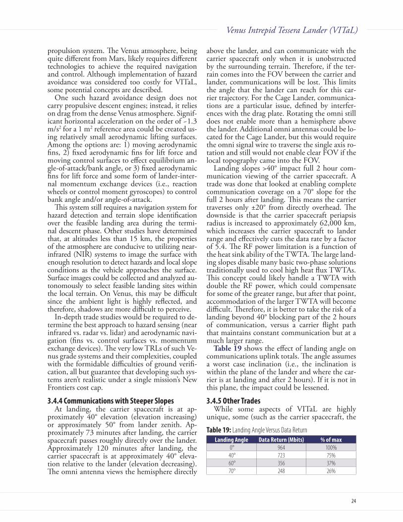
24
Venus Intrepid Tessera Lander (VITaL)
propulsion system. The Venus atmosphere, being quite different from Mars, likely requires different technologies to achieve the required navigation and control. Although implementation of hazard avoidance was considered too costly for VITaL, some potential concepts are described.
One such hazard avoidance design does not carry propulsive descent engines; instead, it relies on drag from the dense Venus atmosphere. Signif-icant horizontal acceleration on the order of ~1.3 m/s2 for a 1 m2 reference area could be created us-ing relatively small aerodynamic lifting surfaces. Among the options are: 1) moving aerodynamic fins, 2) fixed aerodynamic fins for lift force and moving control surfaces to effect equilibrium an-gle-of-attack/bank angle, or 3) fixed aerodynamic fins for lift force and some form of lander-inter-nal momentum exchange devices (i.e., reaction wheels or control moment gyroscopes) to control bank angle and/or angle-of-attack.
This system still requires a navigation system for hazard detection and terrain slope identification over the feasible landing area during the termi-nal descent phase. Other studies have determined that, at altitudes less than 15 km, the properties of the atmosphere are conducive to utilizing near-infrared (NIR) systems to image the surface with enough resolution to detect hazards and local slope conditions as the vehicle approaches the surface. Surface images could be collected and analyzed au-tonomously to select feasible landing sites within the local terrain. On Venus, this may be difficult since the ambient light is highly reflected, and therefore, shadows are more difficult to perceive.
In-depth trade studies would be required to de-termine the best approach to hazard sensing (near infrared vs. radar vs. lidar) and aerodynamic navi-gation (fins vs. control surfaces vs. momentum exchange devices). The very low TRLs of such Ve-nus grade systems and their complexities, coupled with the formidable difficulties of ground verifi-cation, all but guarantee that developing such sys-tems aren’t realistic under a single mission’s New Frontiers cost cap.
3.4.4 Communications with Steeper SlopesAt landing, the carrier spacecraft is at ap-
proximately 40° elevation (elevation increasing) or approximately 50° from lander zenith. Ap-proximately 73 minutes after landing, the carrier spacecraft passes roughly directly over the lander. Approximately 120 minutes after landing, the carrier spacecraft is at approximately 40° eleva-tion relative to the lander (elevation decreasing). The omni antenna views the hemisphere directly
above the lander, and can communicate with the carrier spacecraft only when it is unobstructed by the surrounding terrain. Therefore, if the ter-rain comes into the FOV between the carrier and lander, communications will be lost. This limits the angle that the lander can reach for this car-rier trajectory. For the Cage Lander, communica-tions are a particular issue, defined by interfer-ences with the drag plate. Rotating the omni still does not enable more than a hemisphere above the lander. Additional omni antennas could be lo-cated for the Cage Lander, but this would require the omni signal wire to traverse the single axis ro-tation and still would not enable clear FOV if the local topography came into the FOV.
Landing slopes >40° impact full 2 hour com-munication viewing of the carrier spacecraft. A trade was done that looked at enabling complete communication coverage on a 70° slope for the full 2 hours after landing. This means the carrier traverses only ±20° from directly overhead. The downside is that the carrier spacecraft periapsis radius is increased to approximately 62,000 km, which increases the carrier spacecraft to lander range and effectively cuts the data rate by a factor of 5.4. The RF power limitation is a function of the heat sink ability of the TWTA. The large land-ing slopes disable many basic two-phase solutions traditionally used to cool high heat flux TWTAs. This concept could likely handle a TWTA with double the RF power, which could compensate for some of the greater range, but after that point, accommodation of the larger TWTA will become difficult. Therefore, it is better to take the risk of a landing beyond 40° blocking part of the 2 hours of communication, versus a carrier flight path that maintains constant communication but at a much larger range.
Table19 shows the effect of landing angle on communications uplink totals. The angle assumes a worst case inclination (i.e., the inclination is within the plane of the lander and where the car-rier is at landing and after 2 hours). If it is not in this plane, the impact could be lessened.
3.4.5 Other TradesWhile some aspects of VITaL are highly
unique, some (such as the carrier spacecraft, the
Table 19: Landing Angle Versus Data ReturnLanding Angle Data Return (Mbits) % of max
0° 964 100% 40° 723 75% 60° 356 37% 70° 248 26%

25
Venus Intrepid Tessera Lander (VITaL)
aeroshell, the RF communications architecture, etc.) are very similar, and in some cases identical, to those in the Venus Mobile Explorer (VME) study [2010] completed by the same ADL team for the same customer. After critical inquiry, it was established in a number of areas (such as the carrier spacecraft or the RF Communication architecture), that the conclusions of the VME trades still hold. In those areas, the results of the VME trades were adopted.
3.5 Risk ListThe study team identified three significant
VITaL development risks and three operational risks. Each risk is described in Figure31.
Development Risks1. Safe Landing Assurance: The lander is
equipped with a robust landing system and has plenty of mass allocation, though the de-sign needs considerable non-linear dynamic analysis and drop testing. Development of tessera-like landing scenarios for the drop tests and the inevitable design challenges will commence in the pre-Phase A portion of the mission, lowering this risk.
2. Test Facilities: The “test as you fly” philosophy is challenging for the VITaL probe due to the high temperature, high pressure, and unique venusian atmosphere. Facilities that could be used to simulate Venus entry conditions and Venus surface conditions are not designed to accommodate large test samples. Also, the mission has a two hour lifetime (or less in the case of the aeroshell) and the hardware is ir-reversibly damaged at the end of its mission; that cannot be tested on the ground. Verify-ing basic functionality in a near full scale fa-cility remains crucial to keeping the mission risk within acceptable limits. However, some
functionality needs to be separately qualified with flight-like components to prevent per-manent damage to the flight article. For qualifying the aeroshell, several arcjet facilities for material testing currently exist in the US and around the world. However, there are limitations to achieving applicable conditions in ground test facilities for CP qualification. This is a potential risk, as heri-tage CP is the only material known to work for Venus entries. (See Venkatapathy et al., 2008; 2009 for additional information about qualification and risks associated with VI-TaL. Recommendations have been made to upgrade existing arcjet facilities to generate very high heat fluxes (7-8 kW/cm2) as well as operate in CO2.
3. Raman/LIBS Development: The baseline LIBS instrument needs additional develop-ment to reduce calibration and sizing com-plexities that introduce uncertainty into the measurements, particularly in the Venus en-vironment. Completing demonstration tests in a relevant environment with a similar Laser and Telescope size lowers this risk. The low-est TRL element in the instrument is a 65 mJ laser that can survive the 200 g loads.
Operational RisksA. Landing Risk: There is an inherent risk that
the lander may flip due to unforeseen cir-cumstance (e.g., a boulder or hole). This risk is residual throughout the mission. Missions flown before the VITaL launch could mitigate this risk by providing images and topography to help select the lowest risk landing ellipses.
B. Aeroshell Operations: Due to operations complexity and significant mechanical and thermal loads, the aeroshell may not perform as planned. This is a difficult “test as you fly” component and this risk is residual through-out the mission.
C. Raman/LIBS FOV does not see the surface: If the lander is tilted or lands on a peak, then the Raman/LIBS viewport may not view any surface rocks. The FOV tilts below the plane defined by the drag plates by 10°. If a rock tilts up the lander such that the Raman/LIBS does not view the surface, then the measurements of the surface could not be taken. This risk could be mitigated by additional resources.
3.6 Technology MaturityThe primary requirement for the VITaL design
was to develop the most cost effective lander for VTA022
5
4
3
2
1
1 2 3 54
LIKELIHOOD
CONSEQUENCES
Approach
MedLow
Criticality
TechnicalRisk
OperationalRisk
High
1
A
C
2
B
3
Figure 31: VITaL Risk Matrix

26
Venus Intrepid Tessera Lander (VITaL)
landing in a tessera region. To save on develop-ment, analysis, and testing costs, external mecha-nisms were considered too expensive to imple-ment. Therefore, all mechanisms in the lander as well as the instrumentation are at a fairly high TRL level. The exception is the Raman/LIBS in-strument. VITaL’s Raman/LIBS has a significant two-stage Laser and a large telescope because it is being designed to take measurements 2.5 m away (enabling the 0.86 m survey line for a 20° mecha-nism swing) rather than directly underneath. The laser and optics are similar to other flight lasers and optics, but these have not been designed to survive 200 g. Sensitivity requirements for these instruments also need to be evaluated in depth.
Another open issue is how best to implement the large number of optical windows that all need to be hermetically sealed. This may require some science compromises or structural creativity.
The landing system requires some optimization, and brass board and engineering model testing, but in this concept, no new technologies are required. Finally, a study to evaluate the use of a primary battery versus a secondary battery is recommend-ed. All of these technology maturation plans can be performed within a New Frontier’s schedule, pending independent assessment/development of the state of the art of the Raman/LIBS system.
4.0 DEvELOpMENT SCHEDuLE AND SCHEDuLE CONSTRAiNTS
4.1 High-Level Mission ScheduleFigure32 provides a realistic high-level mission
schedule. The schedule starts with lower TRL item development, resolving development work early before it becomes the critical path. Because of VITaL’s high TRL approach for the baseline Ring Lander, early pre-phase A work can be completed in a New Frontiers baseline schedule. It is impor-tant to develop the landing requirements in a way that can be designed for, analyzed, and tested in a reasonable fashion. The decision as how best to implement the Raman/LIBS (see Section 3 5) and panoramic camera mechanical/optical design in the cupola also need to be resolved early. The mission, as outlined in this concept, does not rep-resent a high development risk mission.
4.2 Technology Development planThe technology development plan requires
technology development to start approximately 1 ½ years prior to SRR. This allows the Raman/LIBS, mechanical structure with windows, pow-er, and landing system designs to be developed sufficiently that the system requirements can be derived and the other subsystem requirements can be baselined. This plan depends on a Venus
ID Task Name Duration Start Finish
1 Phase A: Concept & Technology Development 420 days Mon 8/4/14 Fri 3/11/162 Mission Design Concept / AO Development 6 mons Mon 8/4/14 Fri 1/16/153 LIBS/Raman Development 12 mons Mon 8/4/14 Fri 7/3/154 Venus Environmental Test Chamber complete 0 days Tue 1/5/16 Tue 1/5/165 Landing Ring Design 12 mons Mon 8/4/14 Fri 7/3/156 Comm Relay Design Concept Study 6 mons Mon 1/19/15 Fri 7/3/157 Battery Study 6 mons Mon 1/19/15 Fri 7/3/158 Instrument Announcement of Opporturnity 6 mons Mon 1/19/15 Fri 7/3/159 Instrument Selection 3 mons Mon 7/6/15 Fri 9/25/15
10 Mission Requirements Development 6 mons Mon 9/28/15 Fri 3/11/1611 Mission Requirments Review 0 days Fri 3/11/16 Fri 3/11/1612 Phase B: Preliminary Design & Technology Completion 380 days Mon 3/14/16 Fri 8/25/1713 Systems and Subsystem Requirements Development 6 mons Mon 3/14/16 Fri 8/26/1614 System Requirements Review 0 days Fri 8/26/16 Fri 8/26/1615 Carrier S/C Preliminary Design Development 10 mons Mon 8/29/16 Fri 6/2/1716 Probe Preliminary Design Development 13 mons Mon 8/29/16 Fri 8/25/1717 Carrier S/C Preliminary Design Review 0 days Fri 6/2/17 Fri 6/2/1718 Probe Preliminary Design Review 0 days Fri 8/25/17 Fri 8/25/1719 Phase C: Final Design and Fabrication 400 days Mon 8/28/17 Fri 3/8/1920 Carrier S/C Subsystem Development 6 mons Mon 8/28/17 Fri 2/9/1821 Carrier S/C Critical Design Review 0 days Fri 2/9/18 Fri 2/9/1822 Carrier S/C Flight Hardware Fab & Test 12 mons Mon 2/12/18 Fri 1/11/1923 Probe Subsystem Development 8 mons Mon 8/28/17 Fri 4/6/1824 Probe Critical Design Review 0 days Fri 4/6/18 Fri 4/6/1825 Probe Flight Hardware Fab & Test 12 mons Mon 4/9/18 Fri 3/8/1926 Phase D: System Assembly, Integration and Test, and Launch 685 days Mon 3/11/19 Sat 10/23/2127 Carrier S/C System Level Integration & Test 6 mons Mon 3/11/19 Fri 8/23/1928 Carrier S/C Environmental Test 5 mons Mon 8/26/19 Fri 1/10/2029 Probe System Level Integration Test 6 mons Mon 3/11/19 Fri 8/23/1930 Probe Environmental Test 5 mons Mon 8/26/19 Fri 1/10/2031 Probe to Orbiter Integration & Test 4 mons Mon 1/13/20 Fri 5/1/2032 Spacecraft environmental testing 5 mons Mon 5/4/20 Fri 9/18/2033 Launch Site Campaign 5 mons Mon 9/21/20 Fri 2/5/2134 Mission Slack 9 mons Mon 2/8/21 Fri 10/15/2135 Launch Spacecraft 0 days Sat 10/23/21 Sat 10/23/2136 Phase E: Operations and Sustainment 202 days Mon 10/25/21 Tue 8/2/2237 Cruise phase 111 days Mon 10/25/21 Mon 3/28/2238 1st Venus Flyby 81 days Tue 4/5/22 Tue 7/26/2239 2nd Venus Flyby 5 days Wed 7/27/22 Tue 8/2/22
1/5
3/11
8/26
6/28/25
2/9
4/6
10/23
Q1 Q3 Q1 Q3 Q1 Q3 Q1 Q3 Q1 Q3 Q1 Q3 Q1 Q3 Q1 Q3 Q1 Q32014 2015 2016 2017 2018 2019 2020 2021 2022
VITaL Project Schedule
In Accordance with NPR 7120.5D
Figure 32: VITaL Overall Schedule

27
Venus Intrepid Tessera Lander (VITaL)
test chamber being developed for testing Raman/LIBS under Venus pressure, temperature, and in a CO2 environment so the Raman/LIBS can be sized. The landing ellipse selection process would be enhanced by higher fidelity topography of Ovda Regio acquired before June 2019. This al-lows time for the lander to be targeted to a suit-able region of Ovda that has a high likelihood of a landing location of greatest scientific interest. The current assessment of what is likely to be found in Ovda with macroscale slopes in the 30 to 40° range and lander scale roughness in the 0.5 to 1 m range suggest that the design as is, and Magel-lan scale topography, are sufficient to give a high confidence that landing could be successful.
5.0 MiSSiON LiFE-CyCLE COST
5.1 Costing Methodology and Basis of EstimateVITaL costing methodology for the probe and
carrier spacecraft is based on a combination of parametric cost modeling, analogies to prior mis-sions, and historic cost wrap factors (to account for program support, mission operations, ground systems, etc.). Price H parametric model esti-mates are driven by preliminary Master Equip-ment Lists (MELs). MEL item masses, type of materials, TRLs, and complexity are combined with mission-level cost wrap factors to derive an initial estimated mission cost. A reserve of 50% on Phases A-D and 25% on Phase E is added to the total estimated mission cost, with the excep-tion of the carrier spacecraft, where a 30% reserve is added. The 50% reserve equates to an approxi-mate 70% confidence level in the cost certainty in conventional cost risk analysis. Because Venus surface missions are unique and there are no re-cent landed missions to provide engineering and development constraints, the parametric model cost certainty could be much lower than 70%. No reserve was added to the Launch Vehicle. All costs are in Fiscal Year (FY) 2015 dollars. No grassroots estimate was developed for the study.
5.2 Cost EstimateBased on the Price H model and cost analo-
gies during this study, the team estimated, at 70% confidence level, a VITaL mission concept total cost of $740M to $1.1B (without launch vehicle; $1.3B with launch vehicle). This cost range is at the high end of the New Frontiers cost limit (as-sumed to be $773M FY15, without launch ve-hicle) and into the low end of a flagship mission cost. This cost estimate uses an Atlas V 551. Based on the mass margins, an Atlas V 541 also is ca-
pable of launching this mission and a Atlas V 531 is within 39 kg of being capable. These choices were not available per the study ground rules. This might yield on the order of $20 million in savings. The New Frontiers cost limit is derived from the Planetary Decadal Survey statement of task and is $900 M (FY09 including launch vehicle) x 1.144 (to inflate to FY15) - $257 M for launch Option 5 from the study ground rules (~Atlas V 551). The major technology-development cost for this mission is the Raman/LIBS instrument develop-ment. The mission cost estimate includes $20M to bring new technology to TRL 6. There is also a rigorous development plan for the landing system, including brassboard and EM testing, and fund-ing to support numerous drop tests as well as qual-ify the carbon phenolic process for the aeroshell. The Technology Development plan is provided in Section4 2. Other cost risks were not analyzed in detail and were beyond the scope of this enhanced rapid mission architecture study.
For this mission to more-comfortably fit within a New Frontiers cost, the study team recommends focusing the mission on the three highest priority surface science objectives (Table1). Removing the NMS, TLS, and Magnetometer not only reduces instrument cost but also reduces lander cost and program support costs. As the instrument mass and volume are reduced, the pressure vessel and thermal system sizing can be reduced. The associ-ated system integration and test costs for those in-struments also are reduced. A point design study to increase the cost confidence level is needed to provide a cost for this more focused mission.
6.0 CONCLuSiONSThe tessera regions of Venus provide funda-
mental clues to Venus’s past, but the terrain has been viewed as largely inaccessible for landed sci-ence due to the known roughness. Studies of sim-ilar topography on Earth, the Moon, and Mars, however show that due to gravity forces, high-lands-like regions typically have macro slopes of less than 30°. Stereo SAR Images from Magellan support this finding. Block sizes of similar regions are typically less than 1 m, suggesting the VITaL 1.3 m allowance is more than adequate.
This study report examined the possibility of landing in the highlands of Ovda Regio because its location near the equator ensures that a mission scenario could be found with excellent lighting conditions. Several possible landing ellipses were found that had average slopes on the km scale of less than 30° and do not contain intra-tessera plains. Extensive instrumentation is included in
28
Venus Intrepid Tessera Lander (VITaL)
the design concept to provide high fidelity context images along with extensive mineralogy and el-emental measurements via a Raman/LIBS system. The Raman/LIBS system sizing was explored and a Raman/LIBS Laser and Receiver Telescope were sized. The system is smaller than some laboratory versions due to volume and power constraints, but there is a healthy amount of trade space open to optimize this system. There are trades yet to be performed, including a wider survey versus a more focused one, and high S/N surveys that need to be completed as the concept matures.
The Ring Lander can land on a block 1.3 m high that is sitting on a 30° slope without flip-ping or tumbling. This configuration was trad-ed with alternate designs that had the ability to tumble. The complexity of those landers would have driven design, analysis, and testing costs be-yond the New Frontiers budget goal. Mechani-cally surviving landing on steep slopes is not the only characteristic to consider when landing in the tessera. The data uplink to the carrier space-craft also becomes an important driver for non-flat landings. For local slopes above 40°, part of the lander’s ~2 hour lifetime at the landing site can be blocked by the surrounding terrain. Tol-erating some blockage (which could occur at the beginning or end of the two hours) allowed more data return than altering the carrier spacecraft tra-jectory to a higher altitude and lowering the up-link rate (see Table19). Therefore, the collected science data are prioritized on the lander before transmission to ensure the highest priority data reaches the carrier spacecraft. Landers with tum-bling ability were less capable with uplink perfor-mance than the Ring Lander due to additional structure interfering with the antenna.
The VITaL mission concept has at least 22% mass margin (above the 30% mass growth allow-ance) if launched in 2021 on an Atlas V 551. The estimated cost is within the New Frontiers cost cap, adding the 50% growth allowance pushes it into lower end flagship range. Descopes that focus the mission on high priority surface science will result in a mission cost that better fits in the New Frontiers cost envelope.
7.0 OpEN TOpiCS1. Acquisition (through another Venus mission)
of a topography map of Ovda, Alpha, Tellus, and Thetis tessera regions (with 1 to 2 m class imaging) would help to assess the best land-ing ellipse for mission success. Such a mission is not strictly necessary before flying VITaL, but it might enhance site selection.
2. Raman/LIBS sensitivity studies need to be performed in a Venus-like environment with the detailed optical and laser system detailed in this report to evaluate sensitivities. Like-wise, testing in a Venus pressure and CO2 en-vironment needs to be performed. The g load-ing as a result of the entry angle may drive the laser design. If this turns out to be a major driver, further flight dynamics work needs to be performed to lower the entry angle.
3. Landing System Dynamics, including angu-lar impacts, needs to be evaluated by drop testing prototype landers.
4. The complexity of accommodating large opti-cal windows and interplay with structure and sealing needs to be evaluated. The cupola on top of the lander and the Raman/LIBS win-dows in particular should be engineered and tested on the early pressure vessel design.
5. The size of the Raman/LIBS aperture was driven by the size of the Raman/LIBS optics. Further studies should assess whether Ra-man/LIBS optics can be compacted to allow for a larger aperture window.
6. Flight Dynamics studies to examine addition-al trajectory options should be investigated, as well as finding a 2023 launch date that could land in a tessera region.
7. Additional structural analyses of internal components of the pressure vessel should be conducted.

29
Venus Intrepid Tessera Lander (VITaL)
ACKNOwLEDgEMENTS
NASA/gSFC Study Directors• Martha Gilmore, VITaL Science Co-Champion• Lori Glaze, VITaL Science Co-Champion• Michael Adams, VITaL Study Lead• Gabriel Karpati, Decadal Studies System Lead• Michael Amato, GSFC Planetary and Lunar Lead
NASA/gSFC Systems Engineering• Charles Baker, VITaL Systems Lead• Joanne Baker, VITaL I&T Lead• John Galloway, VITaL• Steven Tompkins, VITaL Ops Lead
NASA/gSFC Engineering Team• Ed Brinker, VITaL Avionics Lead• Jeff Bolognese, VITaL Mechanical Analysis Lead• Brent Bos, VITaL Optics• Heather Bradshaw, VITaL Thermal Lead• Phil Calhoun, VITaL Hazard Avoidance• Matthew Garrison, VITaL Thermal Team• Qian Gong, VITaL Optics Lead• Andrew L. Jones, VITaL Structures Lead• Greg Marr, VITaL Flight Dynamics Lead• Tom Myrick, VITaL Mechanisms Lead• Adan Rodrigues-Arroy, VITaL Communications Lead• David Steinfeld, VITaL Thermal Team• Timothy Stephenson, VITaL Materials Engineer
NASA/ARC Entry Descent Element (EDE) Team• Ethiraj Venkatapathy, EDE Chief Technologist• Helen Hwang, EDE Element Manager• Gary Allen, EDE System Analyst• Ken Hamm, Aeroshell Structural Analyst• Bernie Laub, TPS Element Lead• Todd White, EDE Engineer
NASA/gSFC parametric Cost Team• William Lawson, Parametric Cost Group Lead• Sanjay Verma, Probe and Mission Parametric Cost lead
NASA/gSFC Report Development group• Steven Stuart, Report Development Specialist• Ruth Jennings, Report Graphics Specialist
30
Venus Intrepid Tessera Lander (VITaL)
AppENDiX A – ADL pROCESSTable A1: Using the ADL’s five step process (see appendix), the study accomplished a systematic exploration, down-selection, and optimiza-tion, of the best architecture concepts for VITaL.Step 1: Explore the trade space: expand, filter, and contract
The trade space was expanded to the maximum, then methodically narrowed and filtered through, yielding a list of potential architecture solutions.
Step 2: Build team per preliminary requirements Conducted preliminary analyses of the candidate architectures. Consolidated team with the required expertise, finalized formal study partnership with Ames on aeroshell design.
Step 3: Finalize science payload Compiled a straw-man science payload to serve as the anchor for the mission’s minimum performance requirements.
Step 4: Conduct detailed analyses of viable architecture options
Conducted detailed architecture trades as described below
Step 5: Conducted assessment of architecture Conducted assessment of architecture

31
Venus Intrepid Tessera Lander (VITaL)
AppENDiX B – ALTERNATivE LANDiNg ELLipSES
VTA036Ovda landing elipse 150 x 75 km
76°0’0”E77°0’0”E
78°0’0”E79°0’0”E
80°0’0”E81°0’0”E
82°0’0”E83°0’0’E
84°0’0”E
2°0’0”S
3°0’0”S
4°0’0”S
5°0’0”S
6°0’0”S
7°0’0”S
8°0’0”S
9°0’0”S
10°0’0”S
11°0’0”S
12°0’0”S
2°0’0”S
3°0’0”S
4°0’0”S
5°0’0”S
6°0’0”S
7°0’0”S
8°0’0”S
9°0’0”S
10°0’0”S
11°0’0”S
12°0’0”S
76°0’0”E77°0’0”E
78°0’0”E79°0’0”E
80°0’0”E81°0’0”E
82°0’0”E83°0’0’E
0 30 50 120 180 240Kilometers
Figure B1: Sample VITaL ellipses within Ovda Regio. These ellipses are targeted to avoid intratessera plains and have moderate slopes <40°
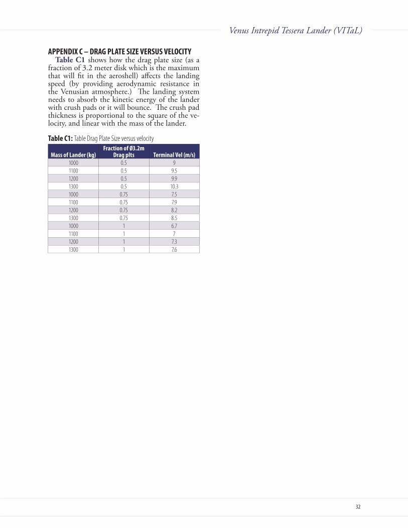
32
Venus Intrepid Tessera Lander (VITaL)
AppENDiX C – DRAg pLATE SiZE vERSuS vELOCiTyTableC1 shows how the drag plate size (as a
fraction of 3.2 meter disk which is the maximum that will fit in the aeroshell) affects the landing speed (by providing aerodynamic resistance in the Venusian atmosphere.) The landing system needs to absorb the kinetic energy of the lander with crush pads or it will bounce. The crush pad thickness is proportional to the square of the ve-locity, and linear with the mass of the lander.
Table C1: Table Drag Plate Size versus velocity
Mass of Lander (kg)Fraction of Ø3.2m
Drag plts Terminal vel (m/s)1000 0.5 91100 0.5 9.51200 0.5 9.91300 0.5 10.31000 0.75 7.51100 0.75 7.91200 0.75 8.21300 0.75 8.51000 1 6.71100 1 71200 1 7.31300 1 7.6

33
Venus Intrepid Tessera Lander (VITaL)
AppENDiX D – AEROSHELL DETAiLS
Table D1: Detailed heat shield and backshell mass estimates Zero Margin
Max Dia,m 3.5BS structure 224BS TPS 69BS Total Mass, kg 293HS structures 269HS TPS (C-P) 449HS Total Mass, kg 717Parachute, kg 40Total, kg 1050
Table D2: Un-margined and margined mass estimates Zero Margin with 30% Margin
Aeroshell Mass 1050 1365Payload mass, kg 1200 1560Total Entry Mass,kg 2250 2925
Note: The carbon phenolic required for VITaL was slightly smaller than VME. Due to increased G’load from a limit load of 175’g for VME to 225 g’ for VITaL, the structure underneath the TPS has to be beefed up.
The CS for the HS was 12 pcf H/C 2” thick with 0.80” thick face sheets.
The CS for the BS was 12 pcf H/C 1.5” thick with 0.050” thick face sheets.
The PICA thickness was not changed from VME to this case.
A thick aluminum mounting ring - 0.125 Sol-id Aluminum Plate Mounting Ring (estimated to be ~80 kg) required to attach the aeroshell to the internal payload was not considered as part of aeroshell but assumed to be accounted for in the mechanical system.

34
Venus Intrepid Tessera Lander (VITaL)
AppENDiX E – CONTEXT iMAgER
VTA00820.00 Millimeters
CCD chipSapphire window
Figure E1: Figure Raman/LIBS context imager

35
Venus Intrepid Tessera Lander (VITaL)
Acronym DefinitionADL Goddard Space Flight Center’s Architecture Design LabARC Ames Research CenterASI Atmosphere Structure InvestigationB billionBPSK Binary Phase Shift KeyingC CelciusC3 launch energyCBE Current Best EstimateCCD Charge Coupled DeviceCD&H Command and Data Handling cg center-of-gravitycm centimeterCMCP Chopped Molded Carbon PhenolicCML Concept Maturity LevelCO2 carbon dioxideCP Carbon PhenolicD/H Deuterium/HydrogenDLA Declination of Launch AsymptoteDOD Depth Of DischargeDSN Deep Space NetworkEDE Entry and Descent ElementEFPA Entry Flight Path AngleEM Engineering ModelFOV Field-Of-ViewFWHM Full Width at Half MaximumFY Fiscal Yearg measurement versus earth gravitational acceleration (9.81 m/s2)GN&C Guidance Navigation and ControlGSFC Goddard Space Flight CenterHGA High Gain AntennaHz HertzI&T I&TK KelvinKa-band Ka-band Communication frequencies of 26.5-40GHzkbps kilobits pers secondkg kilogramkm/s kilometers per secondkW kilowattLNT lithium nitrate trihydratem meterM millionm/s meters per second
Acronym DefinitionMbits MegabitsMEL Master Equipment ListmJ millijoulesMLI Multi-Layer Insulationmm millimeterMOSFETS Metal–Oxide–Semiconductor Field-Effect TransistorMSC/NASTRAN MacNeal-Schwendler Corp (mechanical analysis software)MSL Mars Science LaboratoryNIR Near Infrarednm nanometerNMS Neutral Mass Spectrometer OSR Optical Solar ReflectorsPCM Phase Change MaterialPICA Phenolic Impregnated Carbon AblatorPVLP Pioneer Venus Large ProbeRaman/LIBS Laser Induced Breakdown SpectroscopyRF Radio FrequencyRMS Root Mean SquareS-band 2 to 4 GHz Communications BandS/C spacecraftS/N Signal-to-NoiseSAR Synthetic Aperature RadarSBC Single Board ComputerSINDA Systems Improved Numerical Differencing AnalyzerSRR System Requirements ReviewTLS Tunable Laser Spectrometer TPS Thermal Protection SystemTRL Technology Readiness LevelTWCP Tape Wrapped Carbon PhenolicTWTA Traveling Wave Tube AmplifierV VoltIAU International Astronomical Union (planetary coordinate
system)VEx Venus ExpressVEXAG Venus EXploration Analysis GroupVITaL Venus Intrepid Tessera LanderVME Venus Mobile ExplorerVOI Venus Orbit InsertionW WattX-band X-band is 7.0 to 11.2 gigahertzXRD/XRFS X-Ray Diffraction/X-Ray Fluorescence µm micrometer
AppENDiX F - ACRONyMS LiST
36
Venus Intrepid Tessera Lander (VITaL)
AppENDiX g - REFERENCESArvidson R., R. Greeley, M. Malin, R. Saunders, N. Izenberg, J. Plaut, E. Stofan and M. Shepard (1992)
Surface modification of Venus as inferred from Magellan observations of plains, J. Geophys. Res., 97(E8) doi:10.1029/92JE0134.
Bindschadler, D.L., and Head, J.W., 1989, Characterization of Venera 15/16 geologic units from Pioneer Venus reflectivity and roughness data: Icarus, v. 77, p. 3-20.
Bullock, M. (2009) Venus Flagship Mission Study: Report of the Venus Science and Technology Defini-tion Team.
Campbell, B. and Campbell, D. (1992) Analysis of volcanic surface morphology on Venus from comparisin of Arecibo, Magellan and terrestrial airborne radar data, J. Geophys. Res. 97(E10) doi:10.1029/92JE01558.
Clegg, S. M., Barefield, J. E., Wiens, R. C., Quick, C. R., Sharma, S. K., Misra, A. K., M. D. Dyar, M. D., McCanta, M. C., and Elkins-Tanton, L. (2009) Venus Geochemical Analysis by Remote Raman – Laser Induced Breakdown Spectroscopy (Raman-LIBS), Venus Geochemistry: Progress, Prospects, and New Missions (2009)
Connors C. and J. Suppe (2001) Constraints on magnitudes of extension on Venus from slope measure-ments. J. Geophys. Res., 106 (E2) doi:10.1029/2000JE001256.
Crisp, D., JPL presentation, “The Solar and Thermal Radiation Field below The Venus Clouds”, 2000 Florensky, C. P., L. B. Ronca, A. T. Basilevsky, G. A. Burba, O. V. Nikolaeva, A. A. Pronin, A> M. Tra-
khtman, V. P. Volkov and V. V. Zazetsky (1977) The surface of Venus as revealed by Soviet Venera 9 and 10, Geol. Soc. Am. Bull., 88, 1537-1545.
Ford, P. G. and Pettengill, G. H. (1992) Venus topography and kilometer-scale slopes, J. Geophys. Res., 97, 13103-13114.
Hashimoto G. L., M. Roos-Serote, S. Sugita, M. S. Gilmore, L. W. Kamp, R. W. Carlson and K. H. Ba-ines (2008) Felsic highland crust on Venus suggested by Galileo Near-Infrared Mapping Spectrometer data. J. Geophys. Res., 113, doi:10.1029/2008JE003134.
Herrick R. R., D. L. Stahlke and V. L. Sharpton (2010) A new data set for Venus: Stereo-derived topogra-phy for 20% of the planet at km-scale horizontal resolution, Lunar Plan. Sci. Conf. 41, Abstract #1622.
Ivanov, M. A. (2009) Comparison of RMS slopes of terrestrial examples and tessera terrain, Venus, 50th Brown Vernadsky Microsymposium, Moscow, Russia.
Mueller N., J. Helbert, G. L. Hashimoto, C. C. C. Tsang, S. Erard, G. Piccolini and P. Drossart (2008) Venus surface thermal emission at 1 micron in VIRTIS imaging observations: Evidence for variation of crust and mantle differentiation conditions. J. Geophys. Res. 113, doi:10.1029/2008JE003118.
Sharma, S. K., A.K. Misra, P.G. Lucey, R.C. Wiens, S.M. Clegg (2007) Combined remote LIBS and Ra-man spectroscopy at 8.6m of sulfur-containing minerals, and minerals coated with hematite or covered with basaltic dust, Spectrochimica Acta Part A 68 (2007) 1036–1045
Smrekar, S., S. Limaye, et al. (2009) Venus Exploration Analysis Group Goals, Objectives, Investigations and Priorities.
Wiens, R. C., Shiv K. Sharma, Justin Thompson, Anupam Misra, Paul G. Lucey (2005) Joint analyses by laser-induced breakdown spectroscopy (LIBS) and Raman spectroscopy at stand-off distances, Spec-trochimica Acta Part A 61 (2005) 2324–2334

37
Venus Intrepid Tessera Lander (VITaL)3/31/10
1
Ames Contributing Members Team:Gary Allen, Ken Hamm, Helen Hwang, Bernie Laub,
Jim Ross, Todd White, Ethiraj Venkatapathy
Date: 3/15/2010
3/31/10
Cross Section View of Heat shield and Back shell
2/10/2010 2
Backshell
Heatshield
Landing Ring Crush Ring Crush Plate
38
Venus Intrepid Tessera Lander (VITaL)3/31/10
2
• Components:– Heat shield, Back Shell and Parachute – Heat shield: Carbon Phenolic bonded to a 2” Honeycomb ( Al with
Composite face-sheet)– Back shell: PICA tiles bonded to a 1.5” Honeycomb (Al with Composite
face-sheet)– Parachute sized based on simple mass scaling ( 3 *( P-V large probe
parachute) based on guidance from Pioneer Aerospace) • Key Assumptions:
– Ve = 11.3 km/s; EFPA = -23.35 deg; Max Dia: 3.5; P-V scaled
3/31/10
Detailed Mass Summary
3/31/10

39
Venus Intrepid Tessera Lander (VITaL)3/31/10
3
3/31/10
Chop Molded C-P
Tape Wrapped C-P
Carbon Phenolic
AL Honeycomb
Face Sheet
Face Sheet
Avrg. Thickness of C-P: 2.325 cm” Face Sheet: 0.08 in
Al H/C (12 lbs/ft3) density at 2” thick Carbon Phenolic Mass: 449 kg Carrier Structure Mass: 269 kg
HS Total Mass 717 kg
• Back shell TPS is PICA tiles bonded to the underlying carrier structure ( Al H/C with composite face sheet.
• Approximately 100 PICA tiles ( 1.25 cm x 39.7 cm x 39.7 cm) • The tiles are bonded to the CS with 20 mil HT-424 adhesive • The tile gap between tiles are filled with RTV (80 mil gap)
3/31/10
PICA
HT-424
H/C System
PICA Thickness: 1.25 cm HT-424: 20 mil
HC face sheet: 30 mil HC: 1.5 inch
PICA Mass: 52.8 kg HT 424 Mass: 12.9 kg RTV Carrier Structure Mass: 223.9 kg
Total TPS mass (PICA+RTV+HT424) 68.93 kg
Total backshell structures mass 223.93 kg
Area of Backshell 15.79 m2 Areal Density of BS: 14.18 kg/m2
Total Back shell mass: 292.85 kg

40
Venus Intrepid Tessera Lander (VITaL)3/31/10
4
• HS Mass Sensitivity Carpet plot • BS PICA Thickness Sensitivity Carpet plot • Max conditions (EFPA of -23.35 deg and ballistic coeff of 294 kg/m2)• ViTAL Aeroshell Structure • Aero stability Assessment: Comments on Lander Configuration • Preliminary Experimental Low-Speed Drag and Stability
Measurements of Potential Probe Configurations (6/19/03)
3/31/10
3/31/10

41
Venus Intrepid Tessera Lander (VITaL)3/31/10
5
3/31/10
PICA thickness on the back shell is decided based on manufacturing and handling consideration: 1.25 cm ( is >> PICA thickness needed based on engineering estimate of thermal load)
Raj Venkatapathy G. Allen
3/31/10
42
Venus Intrepid Tessera Lander (VITaL)3/31/10
6
Max Conditions including G’load during entry for Ve= 11.3 km/s and Ballistic Coefficient of 294 kg/m2
G’load Profile during entry for Ve= 11.3 km/s and Ballistic Coefficient of 294 kg/m2

43
Venus Intrepid Tessera Lander (VITaL)3/31/10
7
ViTAL Aeroshell Structure Sizing Iteration 2
February 3, 2010
Design Assumptions • Geometry is similar to Pioneer Venus (45 degree sphere cone)
scaled up to max diameter • 3.5 M
• Internal Payload of 1500 kg (3300 lbs) • NSM for Carbon Phenolic HS 1” thick ( = 0.0534 pci) • Deceleration load of 225 G.
• Modeled as uniform pressure normal to Aeroshell surface • 3.5 M => 121.86 psi
44
Venus Intrepid Tessera Lander (VITaL)3/31/10
8
Model Geometry
• Shell Elements used throughout • Composite Modeling - .080” Aluminum Face sheets – 2.0” Al core (12 pcf) • Inertia Relief Analysis used
Outer Surface Inner Surface
Face Sheet Stress
Outer Face Sheet Max Von mises Stress = 29 ksi
Inner Face Sheet Max Von mises Stress = 36 ksi
Assuming 2024-T3 Facesheets: Ftu = 64ksi, Fty = 47ksi, Fcy = 39ksi, Fsu = 39ksi Min Margin (Compression Yield) = +0.08 (FoS 1.4, 1.0)

45
Venus Intrepid Tessera Lander (VITaL)3/31/10
9
Core Shear
Max Shear = 542 psi Shear Strength (min) = 1000 psi
Margin = +0.32 (FoS 1.4)
Mounting Ring
Max Von Mises = 32 ksi Compression Yield = 39 ksi
Margin = +0.22 (FoS 1.4, 1.0)

46
Venus Intrepid Tessera Lander (VITaL)3/31/10
10
Mass• Based on Stress Results seen for 3.5M Configuration
– Configuration• 0.080” Face Sheets - Aluminum 2024-T3 • 2.0” 1/8”-5052-.003 Aluminum Core (12pcf) • 0.125 Solid Aluminum Plate Mounting Ring
– 3.5M Aeroshell Mass with the mounting ring = 768 lbs (349 kg)• Includes Mounting Ring • 1” Carbon Phenolic HS assumed = 1103 lbs NSM
– The mounting ring is considered part of the mechanical system and hence not included in the Aeroshell Mass
• Heat shiedl structural mass is: 269 kg
• More optimization needed– Contingency of 30% should be included on Mass Estimates – No Back Shell Mass Estimated – No Other Internal Structure Mass Estimated
Aero stability Assessment:Comments on Lander Configuration
Jim RossCode AOXFeb 2010

47
Venus Intrepid Tessera Lander (VITaL)3/31/10
11
Initial thoughts based on this image• Good high-drag configuration • High “aspect ratio” – short and wide –
may lead to static and dynamic instability– Center of pressure is close to center
of gravity – Wake from wide drag disk could
couple with probe pitch motion leading to dynamic instability
• Landing ring wake can interact with the drag disk during pitch oscillation also leading to a static and/or dynamic instability
• The sharp corner on the drag disk is good but the circular shape may have periodic shedding – may be better to have several notches around the perimeter
Preliminary Low-Speed Drag and Stability Measurements of
Potential Probe Configurations 6/19/03
Jim Ross, et. al.

48
Venus Intrepid Tessera Lander (VITaL)3/31/10
12
Configurations Tested
Case 1: Baseline
Case 2: With landing ring (scaled off Venera photo from web)
Cases 4 & 5: Fixed grid fins instead of drag plate - without (4) & with (5) landing ring
Configurations Tested, cont.
Cases 8 & 9: Sphere and Venera- size disk - without (8) and with (9) landing ring
For moment measurements, axis of torque sensor passed through the cg location indicated
CD =D
r2
qCM =
M
r3
qMoment measured at 0 & ±5°
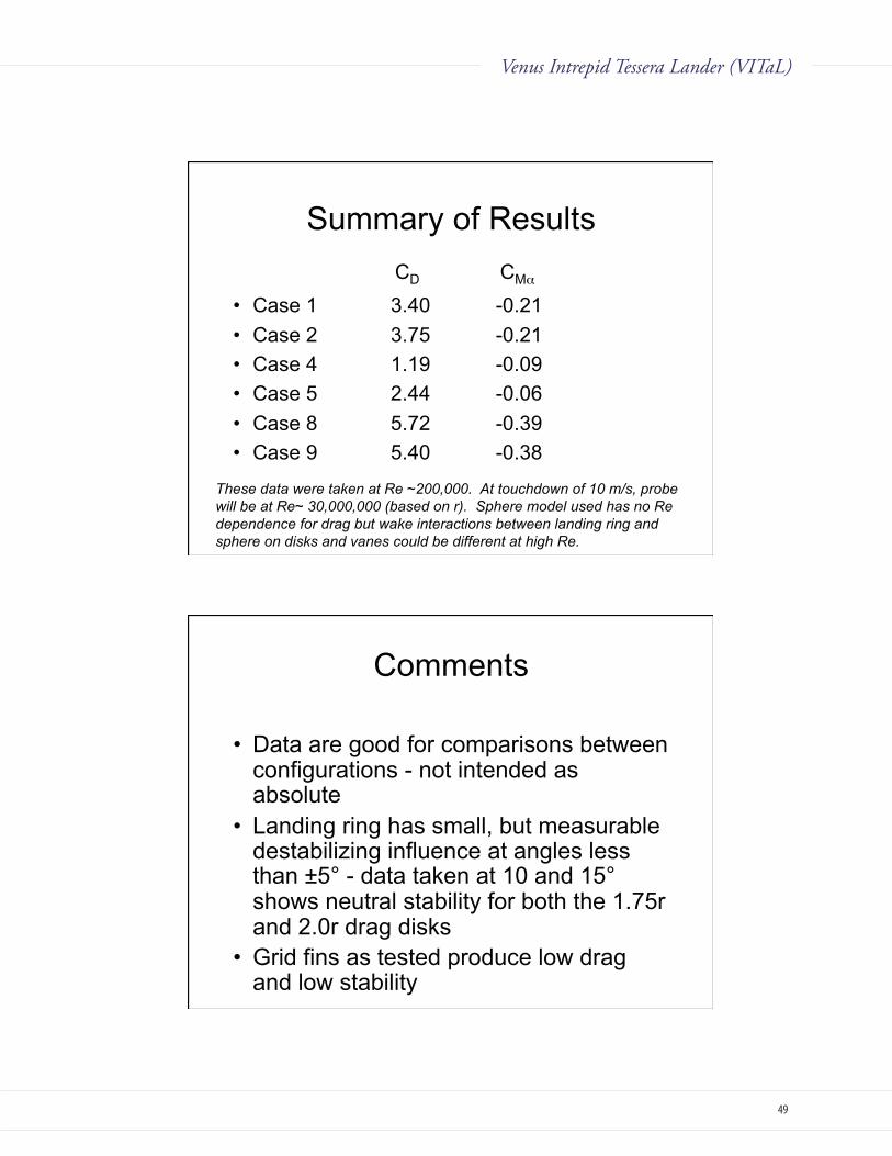
49
Venus Intrepid Tessera Lander (VITaL)3/31/10
13
Summary of Results
• Case 1 3.40 -0.21 • Case 2 3.75 -0.21 • Case 4 1.19 -0.09 • Case 5 2.44 -0.06 • Case 8 5.72 -0.39 • Case 9 5.40 -0.38
CD CM
These data were taken at Re ~200,000. At touchdown of 10 m/s, probe will be at Re~ 30,000,000 (based on r). Sphere model used has no Re dependence for drag but wake interactions between landing ring and sphere on disks and vanes could be different at high Re.
Comments
• Data are good for comparisons between configurations - not intended as absolute
• Landing ring has small, but measurable destabilizing influence at angles less than ±5° - data taken at 10 and 15° shows neutral stability for both the 1.75r and 2.0r drag disks
• Grid fins as tested produce low drag and low stability