Ventilation at the Portovelo mines
29
Scholars' Mine Scholars' Mine Professional Degree Theses Student Theses and Dissertations 1932 Ventilation at the Portovelo mines Ventilation at the Portovelo mines John Paul Harmon Follow this and additional works at: https://scholarsmine.mst.edu/professional_theses Part of the Mining Engineering Commons Department: Department: Recommended Citation Recommended Citation Harmon, John Paul, "Ventilation at the Portovelo mines" (1932). Professional Degree Theses. 241. https://scholarsmine.mst.edu/professional_theses/241 This Thesis - Open Access is brought to you for free and open access by Scholars' Mine. It has been accepted for inclusion in Professional Degree Theses by an authorized administrator of Scholars' Mine. This work is protected by U. S. Copyright Law. Unauthorized use including reproduction for redistribution requires the permission of the copyright holder. For more information, please contact [email protected].
Transcript of Ventilation at the Portovelo mines

Scholars' Mine Scholars' Mine
Professional Degree Theses Student Theses and Dissertations
1932
Ventilation at the Portovelo mines Ventilation at the Portovelo mines
John Paul Harmon
Follow this and additional works at: https://scholarsmine.mst.edu/professional_theses
Part of the Mining Engineering Commons
Department: Department:
Recommended Citation Recommended Citation Harmon, John Paul, "Ventilation at the Portovelo mines" (1932). Professional Degree Theses. 241. https://scholarsmine.mst.edu/professional_theses/241
This Thesis - Open Access is brought to you for free and open access by Scholars' Mine. It has been accepted for inclusion in Professional Degree Theses by an authorized administrator of Scholars' Mine. This work is protected by U. S. Copyright Law. Unauthorized use including reproduction for redistribution requires the permission of the copyright holder. For more information, please contact [email protected].

VENTIL.~TION AT THE PORTOVELO MINES
by
John P. Harmon
A
THESIS
Submitted to the faculty of the
SCHOOL OF ~!INES AND METALLURGY OF TIrE UNIVERSITY OF 1~ISSOURI
in partial rulr11lment of the work required for the
DEGREE OF
ENGmEER OF MINES
Rolla, Mo.
1932·
Approved by ~PROYESSOR OF MmmG

Ventilation at the Portovelo Mines
Table of Contents
Page
General Description ------------------------------------
Sur~ace Temperature ------------------------------------
Humidity -----------------------------------------------
Ventilation in the Past
3S68
Preliminary Conclusions -------------------------------- ~
Fan Installation --------------------------------------- II/
Evase Chimney ------------------------------------------ /2•
Auxiliary Ventilation --;------------------------------- 15
Ore Transfer Raise Used as Airway ---------------------- 18
Air Splits ~--------------------------------------------18
Cooling Air for Ventilation Purposes .------------------... , S
Mine Fires ------------------------~--------------------20
Method of Taking and Recording Observations Underground-21
Conclusions --------------------------------------------23Acknowledgments ----------------------------------------26Ble~1 D6-RRPH Y -- -- - - -- --- ---- ------- -- --------------- - - -- 27
I

List of Illustrations
PageFig. 1.- Profile of Portovelo Mine Workings
Considered in Ventilation Problem
Table 1.- Monthly Average Maximum and Minimum
Temperatures as Recorded at Portovelo Ecuador 1Table 2.- Portovelo Rainfall Record in Inches 7Fig. 2.- Plan of' Seventh Le'vel Station and
Fan Site ---------------------------------------- 7Fig. 3.- Parallel set-up of two Exhaust Fans
on !'Aft Level ---- .... ------------------------------- 7
Table 3.- Velocity Pressure in Relation to Length
of Chimney --------------'------------------------ ,,,
Fig. 4.- Modder Blower -------------------------- /3
Fig. 5.--,Curve showing advantage of using the
larger size of canvas pipe -~-------------------- J~
Fig. 6.- Nozzle for diffusing compressed air in
raises --------------------------------~--------- 17Fig. 7.- Ventilation system in North part of
Mine -----------------------~-------------------~ 17
Fig. 8.- Mine Record Sheet ---------------------- 22Table 4.- Temperatures Recorded in the Portovelo
Mines
z
25

Ventilation at the Portovelo Mines, Ecuador*
This paper was written with two objects in
view: (1) To describe in detail what has been done to
ward the ventilation of the main unit of the Portovelo
mines and the results; (2) to give information that may
be useful to anyone who may have to make a preliminary
mine ventilation survey, with recommendations for the
improvement of the existing system and finally the
maintenance or the improved system.
General Description
The mining operations of the South American
Development Co. at Portovelo, Province of El Oro, Ecuador,
are described here only briefly, as a full discussion
does not fall within the scope of this paper.
The orebodies are o~ the .steeply dipping, gold
quartz vein type, averaging about 2.0 meters wide. As
shown in Fig. 1, the ore chutes are relatively far apart,
making considerable deve.lopment work necessary before
connecting raises can be driven between the levels.
Faultingl _on a large scale and a parallel vein system
have made long dead-end drifts and many crosscuts neces
sary in the exploration of veins. The ventilation of
these dead ends is described under Auxiliary Ventilation.
The method of miningS is the filled rill stope method,

A Level
ThIrd Level
Fourth] 0 {iITel
·'9 Fifth Level 1 ·t~ ~."::"'--~~~~--~I'----r---"'" ""'--- \()~::~-~r:L..
~··~o ~-
Sixth L~e~ve:...:../--A.:lj~~~~~~~~~ ~o ~(lJ~
~~ ~oo~·f..~o . ~~Sevenfh L:.::e:.:.Vi..::.e~r~.t'-__~~_--~:::--'.....J ..._~.....--_-.J 1..- _
FIG. l.-:-PROFILE OF PORTOVELO MINE WORKINGS CONSIDERED IN VENTILATION PROBLEM.
-------------_....-...__ ._..•_-_._-_.---_._----
TABLE I.-Monthly Average Maximum and Minimum Temperature asRecorded at Portovelo, Ecuador
vearl Jan. I Feb. I Mar. I Apr. I May I June I July IAug. ISept. I Oct. INov. I Dec.
§ IMax... 75.8176.4178.0 78.9180.4 80.91 82. 5 81. 5 1 80 . 1 81. 5 1 81.9 82.6~ ----------\--1-----
Min... 68.8 69.5 69.8 69.5 69.3 67.6 65.3 66.5 67.6 68.3 68.9 68.9==========-===========-=================-::::==::=.======-=====-===============-00 Max... 77.0 77.0 78.5 79.0 78.5 78.5 81.1 80.6 82.5 83.5 82.6 81.4~ ---------------------------------------~ Min... 67.9 68.1 67.6 68.0 68.5 66.7 64.2 65.6 67.1 67.9 67.7 68.3
~ Max... 79.5 77.2 78.6 79.6 78.8 78.6 81.5 81.2 82.9 82.3 81.6 80.2~ --------_._-------------------~ Min... 67.2 67.9 68.0 67.5 67.7 66.3 64.1 65.7 67.1 67.2 67.5 68.0- -==================================--=====-===========~ Max... 79.5 77.4 ~I 79.2 _1__1__1__1_-_
~ Min... 67.8 67.4 68.0 1 67 . 8 I .
4

similar to the method that is largely employed at the
Butte mines.
The main shaft of the mine is in the Amarillo
Valley, on either side or which mountains rise abruptly
to a height -of several hundred feet above the collar orthe shaft. Entrance is made to the mine: (1) Through
the American sha~t, which extends vertically from the
sur~ace to a depth of 1100 ft., of which only the first
700 ft. are in active use at the present time; (2) levels
are driven from the American shaft at intervals of 30 m.
(100 ft.), of which only the third, rifth and seventh
levels need be considered in the ventilation problem;
(3) adits at intervals of 30 m. (100 ft.), with a faw
exceptions, above the collar or the Amari-can shaft. The
main adits on the south side are 3/4 level adit, A level
adit, E level adit, El/4 level adit and F level adit.
surrace--" Temperature
A record or the maximum and minimum daily
temperature readings has been kept for a period of 30
yearse. This record shows that the average maximum
temperature for the last four years has been 80.8 0 F.
and the average minimum 68.2° F. It also shows that the
difference between maximum and minimum monthly average
for the last four years has ranged between 6 D and 20D F.
Table 1 shows the maximum and minimum average monthly
temperature for the years 1927, 1928, 1929 and 1930 to

date. The temperature readings were taken in the
shade and indicate only the air temperature, which is
not high enough to require rerrigeration for mine ven
tilation purposes, nor low enough to materially change
the mine temperature.
Humidity
At the latitude of the mine there are two
distinct seasons of the year; the wet season, December
15 to June 15~ and the dry season, June 15 to December
15. During the wet season rains occur daily, averaging
about 60 in. of rainfall per year. In the dry season
there is very little prec1patat1on. (See Table 2.)
The humidity of the air on the surface is
higher than might be .expected, especially during the dry
season. A record of the relative humidity at the collar
of the American shaft shows that the average for the period
July 15 to August 15 was 48 per cent.; that from May 8
to June 8, 64 per cent.
The humidity of the mine air, however, is in
dependent of the surface humidity and the air attains a
high relative humidity soom after entering the mine. The
high humidity is due to:'
1. Mine water. Enough water seeps from the
rocks to keep the back or many of the drifts and stopes
permanently wet, and in some places there 1s such an ex-
6
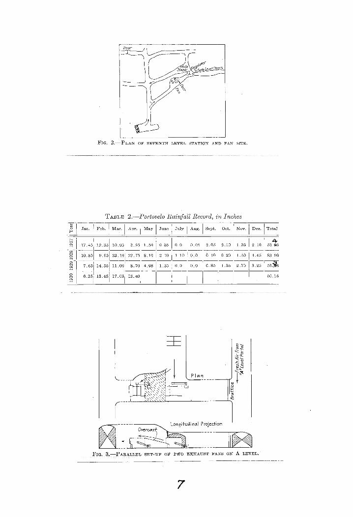
FIG. 2.-PLAN OF SEVENTH LEVEL STATION AND FAN SITE.
TABLE 2.-Portovelo Rainfall Record, in Inches
~ II Jan. i Feb. I Mar. I Apr. I May I June I July I Aug. I Sept. I Oct. I Nov. I Dec. ITotal
~ (i I I I I I I I 4_: II 17.45 12.35 lo.95~~I~~I~2.05 =~~ 2.10 53.~5§l II 10 .851 9 . 65 1 23. 10 I 22. 751 8. 10 I 2. 10 11. 10 1 o. 0 O. 10 0 . 20 1. 50 4.45 83 .90
~ I' 7.65114.55111.001 .8.701~ 1.35 i~~ 0.85~~ 3.25 56jg---1-1----- --§. :6.25113.45117.05 13.401 i 50.15
---------------_._---_._---_.-._---~_._-_..-
PIOIn
8-----... LongitudinOil Projection
-~ ~ ~~~~~~FIG. 3.-PARALLEL SET-UP OF TWO EXHAUST FANS ON A LEVEL.'
7

cess as to rorm drippers. /
2. Underground streams. In several places
underground streams have been tapped, which have tended
to saturate the air.
3. Water from drills. To reduce the possibility
of the miners contracting silicosis, dry drilling 1s pro
hibited. Although there is less water from wet drilling
than from the sources mentioned above, it tends to keep
the relative humidity at the working places very near 100
per cent.
4. Perspiration ~rom men and animals underground.
This source of moisture, although small, locally tends to
saturate air of low velocity that might otherwise be fairly
dry.
Ventilation in the Past
The system of ventilation in operation before
the changes described in this paper were made was as follows:
A Sturtevant, Silentvane No. 95, design 2, double
width double-inlet fan, located at 3/4 level portal, ~orced
fresh air along the drift (Fig. 1). Some air passed up
through the 3/4 level stopes and out to the surface; the
remainder passed down to third level through two operating
stopes. From third level. the air was forced to fifth level
through two operating stapes, and then to seventh level
through a manway. The air on third level and fifth level
was kept from returning to the American shaft by doors in

the drift south of the shaft. On seventh level the air
went north, past the American shaft, where it was di
luted with fresh air.
A booster fan of local make was placed on
seventh level, north of the American shaft, and a
sturtevant fan similar in design and capacity to the
one at 3/4 level portal was located at F leval portal,
in the north end of the mine (Fig. 7). These two fans
working in series exhausted the air from the mine. The
American shaft was kept downcast, to preserve the shaft
lining, which at that time was wood.
Under this system the maximum amount o~ air
circulating in the mine was 33,000 cu. ft. per minute,
as all of the fans operated in series.
Air splits are considered essential in good
ventilation praetiee, and in some pa~ts of the United
states they are reqUired. As stated later, the new
system or- ventilation was""based on this principle~ while
the old system worked on a series plan, using the same
vitiated air over and over again.
Preliminary Conclusions
Af't·er a preliminary study of the problem of
ventilating this mine the following conclusions were
reacl~ed:
1. That the pressure system employed in the
south' pavt of the mine should be changed to an exhaust
9

system. This change was decided upon because: (a) It
was desired that air splits be employed as ,frequently
as practicable, in order that partly vitiated air might
be diluted before passing to the next working place.
The use of air splits, while possible with a pressure
system, can be handled more easily with' an exhaust
system. As was noted under Ventilation in the Past,
the same air was used over and over, so that it was
thoroughly vitiated on reaching the exhaust passage.
(b) With the two fans in series, as in the original set
up, approximately 33,000 cu. ft. of air per minute was
circulated through the mine, while with the same two
fans exhausting independently twice as much air was ,
circulated.
2. That a line of raises should be driven
in the south part of the mine, to be used primarily for
ventilation purposes.
3. That the fan which had been forcing air into
the south part of the mine should be moved to the Tablon
shaft, where the air raise from B level to the surface had
broken through.
4. That the booster fan formerly mounted north
of the American shaft on seventh level should be moved
south of the shaft, to force air south to sixth level
stopes, as well as deliver some air north through the
mule stable (Fig. 2).
10

5. That a system of air splits should be
adopted as far as possible.
6. That solid platforms in raises to be
used for airways should be replaced by lattice plat-
forms •.
7. That it would not be practicable to reduce
the humidity of the mine air.
8. That, due to the h~gh humidity and pre
vailing rock temperatures, large quantities of air·at
high velocity would be necessary at all working places.I
9. That it.would not be advisable to: precool
the air to be used for ventilation.
Fan Installations
An untimbered inclined raise was driven from
B level to the surface, about 700 m. (2300 ft.) south
-O-.f-... B level portal. A Sirocco :raB designed to exhaust
60,000 cu. ~t. or air per minute with 31/2-in. water
gage has been installed in the fan house at the collar
or this raise, replacing the 33,000 cu. rt. per minute
fan that was placed there as a temporary installation.
The' fan house wa.s constructed o~ crosslapped boards,
gunnited on the outside to make the walls fire-resisting
as well as airtight. The roof was made airtight by in
serting a layer of tar paper between the crosslapped boards.
Two Sturtevant fans, each designed to deliver
33,000 cu. £t. of air per minute against 31/2-in. water
gage, are to be installed in the north part of the mine.
II

Fig. 3 shows that these fans can be operated either in
series, in parallel, or singly, depending upon conditions
in the mine as they change rrom time to time. Changing
conditions will determine the mode o~ running fans. Tests
were made, and at the present time the fans will operate
best in parallel. Later, as resistance in the ventilation
circuit increases, it may be necessary to run the fans in
series. In general, if the mine has high resistance, two
fans will deliver more air when operating in series; with
low resistance, two fans will deliver more air when operat
ing in parallel. 3
At present no mining is being done in the
Cantabria stopes, so that these raises and stopes are kept
open for the exhaust air from the A level fans. Later,
however, after the Soroche and Tamayo stopes are exhausted,
the Cantabria stopes will again be worked. ~~en men are
working in the Cantabria stapes, they can be furnished
with fresh air from the same fan set-up, merely by replacing
the brattice shown in Figs. 3 and 7 by a regulator. The
air then will enter the portal at A level, pass through the
fan, up through Cantabria and out. The amount of air left
circulating through Soroche and Tamayo stopes will be con
trolled by the regulator.
Evase Chimney
When a fan is working as an exhauster, the air
leaves the fan at high velocity, causing a high percentage
/2

TABLE. 3.-Velocity Pressure in Relatio·n to Length of Chimney
0I
0.000I 8 1.382
1I
0.323 I 9 1.4492 0.580
I10 1.506
3 0.787 11 1.5554 0.955
i12 1.597
5 1.092 13 1.633i6 1.206 I 14 1.664
7 1.302 I 15 1.691I
Length of Chimney, Ft. I Velocity Pressure Re- :1 Len th of·Chimn Ft I Vel~city Pressure Re-covered, Lb. per Sq. Ft. ; g ~y, . covered, Lb. per Sq. Ft.
i
--l! . •.._~~ .,_~._! . ._._. __ .__ ..__.._. __
~....., ....... - • " -- - - - - - - - - - - . - - v
___"~-~ 'Iron Rod welded to Blower~~~O'2" forf'asfening Canvas Tube
:::: '-=x- Br~ss Nozzle~'L for C0'!1pressed
II AIr Injector0.25
FIG. 4.-MoDDER BLOWER.
600 1000 1200 1400 1600 t800 2000Length oft~nva5 Pipe J ft.
600
I--~1---1""""
l.---~~
~~v---
VV
/'
FIG. 5.-CURVE SHOWING ADVANTAGE OF USING THE LARGER SIZE OF CANVAS PIPE.
/3

loss of kinetic energy. If the air leaving the fan can
be slowed down (made to rise to atmospheric pressure
gradually) some of the velocity pressure is converted
to static pressure.
The Evas~ chimney is an old device for re-
covering static pressure on exhaust fans, but I believe
a description o~ how we designed the chimney for our
~an may well be given here. The chimney should expand
gradually, otherwise eddy currents are set up and the
recovery is poor. Let the area at the fan discharge be
Al and the area at the top of the chimney A2. Let Q be
the quantity flowing in cubic reet per second. Then the
velocity at the throat is Q/Al and the velocity at "the top
is Q/A2. The velocity pressures at these two points are
WQ2/2GAl and WQ2/2GA2, where W is the ~eight of 1 cu. ft.
of air. If conversion is perfect, the velocity pressure
recovered is WQ2 (12 ~ b) As the conversion is never2G lA-I A2 '
perfect, a factor representing the efficiency of conversion
must be used. A chimney with a 10 per cent. slope was de
cided upon. W. H. Carrier4 gives 70 per cent •. for the
efficiency of a conical diverging nozzle with a 10 per
cent. slope.
The tabulation in Table 3 was made from the
above formula. These data were plotted on rectangular
coordinates, from which it was apparent that an appreciable
saving is made by using a chimney 10 £t. long, while be
yond that point the velocity pressure recovered is not
14

appreciable per unit length of chimney. Therefore a
chimney 10 ft. long was decided upon as economical.
Auxiliary Ventilation
Here, ~s at other mines, the problem of
furnishing fresh cool air to dead-end workings can•
best be solved by using small electrically driven fans,
delivering air to the face through canvas tubes. At
present there are two Coppus TM-6 fans and t~o Sirocco
21/2 Troy fans, which are used where relatively long
lengths of canvas tube are needed.
Where conditions make the installation of an
electric blower impracticable, an injector blower of the
Madder deep type (Fig. 4) has been round convenient and
effective, when the distance for delivering the air is
not over 300 ft. As these blowers, made in the machine
shop at a low cost~ have no moving parts, there is nomaintenance cost, and since they require only a common
air hose connection they can be installed qUickly and
easily. Where the face to' be supplied with fresh air
by an electric blower 1s too far ror erfic1e~t operation,
an injector blower has been found effective, installed
directly in the line about one-third of the distance from
the fan to the face.
The outlet of the canvas tube should be as
close to the workers as convenient, never farther away
IS

than 25 ft. Hence, two short sections of tube (25 ft.
and 50 ft. long) are furnished to the men in each dead end.
\~en a face has been advanced 25 ft. beyond the last 100
f't. section of tube, a 25-:rt. section is. put on. After
another 25-ft. advance, the 25-ft. section is replaced
by the 50-ft. section, and ~inally the 25-ft. section is
added, making a total or 75 ft. Thus the end of the tube
is kept within 25 rt. or the ~ace at all times.
~~en canvas tubing was first used for ventilating
dead ends in this mine, the miners did not understand the
necessity ror keeping the tube hung properly, in good repair
and free from holes, and for keeping it close to the face.
The tube was placed near the working place, in spite of the
workers, and now they seem to realize the improved working
conditions and maintain the tube themselves.
Some time ago a considerable quantity o~ 12-in.
Ventube was stocked. Vfuen the next order is made, it will
probably be for 16 in. tube, because of its increased
ef~ic1ency (Fig. 5). For rurnishing air to men working in
raises while no drilling is being done, a compressed-air
hose is used, with a special nozzle. The nozzle (Fig. 6)
was made in the mine machine shop. The body is packed with
waste to prevent free. escape of air. As expanding air
absorbs considerable heat, a given quantity of compressed
air will have a greater cooling and drying e~fect than ~
/6

Cap..~
Wasfe Packing
{Reducer
___________ 7/1 - • ---.J Pipe CffP drJlJedwith 1J5dia.Holes
FIG. 6.-NoZZLE FOR DIFFUSING COMPRESSED AIR IN RAISES.
ntobaj~Ca. stopes ~Vem
FIG. 7.-VENTILATION SYSTEM IN NORTH PART OF MINE.
17

like quantity of air forced to the back through canvas
tubing.
Ore Transfer- Raise Used as Airway
On several occasions it has been nec.essary to
use a one-compartment long raise for an ore transfer as
well as for an airway. An existing raise can be made to
serve both purposes at a cost much lower than that of
driving a completely new raise. This is done by driVing
a new small raise 15 ~t. from the old one, the height de
pending upon the'size of the old raise and the desired
capacity of the ore chute. The two are then connected by
a raise inclined up from the old raise, so that muck dropped
through the transrer cannot fall into and block the ven
tilation raise. This plan, tried twice, works well so
long as the chute is kept drawn down below the connection
(Fig. 7).
Because of the large quantity of water in all
parts of the mine, :there is -no dust underground, there
fore there is little objection to a high velocity in the
mine airways. When the velocity 1s surricient to make a
candle rlame rlicker badly, electric lights are used.
Air Splits
Every advantageous opening for admitting air
to the mine workings is utilized. This, of course, must
hot be understood to mean all openings, for some entries
have to be blocked by doors or brattices to force the air
18

to traverse the lowest working level and not short-circuit.
This is done for several reasons; besides putting different
parts of the mine on independent air sources, the velocity
in anyone entry for the same total ·volume of air is great
ly reduced, with consequent reduction in the resistance
ofrered to the rlow of air in the mine. The reduced re
sistance in turn allows more air to flow.
Air enters the south part of the mine through
A level and 3/4 level portals,-splits and goes to the
lower levels through the Tablon underground shaft and an
abandoned stope (Fig. 1). The former split delivers air
to the third and fifth levels, while the latter delivers
fresh air to the ·fifth level only.
The mine north of the American shaft receives
fresh air through A level portal and an abandoned stope
that opens into C level and D level portals (Figs. 1 and 7).
Cooling Air for Ventilation Purposes
Inasmuch as the rock temperature at the present
depth of mining is not over 91°F., there is no special
need ror refrigeration, even locally.· Sufficient fresh
circulating air will cool· the working places to a com
fortable working temperature.
Water sprays have been tried for cooling, but
were ~ound unsatisfactory, because the temperature of the
air was so nearly the same as that of the cooling water
that very l~ttle cooling resulted from letting the air
pass through a number of sprays.
/9

11ine Fires
It is believed that there is little danger
of serious fire in this mine, for the following reasons:
(1) Little timber is needed, as the cut and fill method
of stoping is used; (2) the water in the rock cavities
and the high relative humidity of the mine air keep a
great part of the timber damp, (3) green timber is
used; (4) all timber is of hard wood; (5) there is very
little timber in the hoisting shafts. The American
sha~t is concrete cribbed and the guides in the Tablon
UhdergroUnd-shaft are carried on stulls./
The fire hazards might be listed as follows:
(1) Underground store houses; (2) electrical equipment
in the mine; (3) accumulated inflammable re~use left on
the levels.
The fan houses are designed so that the direction
of air in the mine can be reversed if necessary. A list
of contingencies that would necessitate the reversal of
the fans is too long and varied to be of interest here.
The\ decision as to whether the fan should be reversed or
not should be left to some one thoroughly familiar with
the air currents in the mine and the effects that the re-
versal would have upon the existing currents.
In making any decision as to changing the
direction-of air flow by manipulating the fan, the questions
to be considered are: Will the new condition create a
passage that will be free from smoke and gas, through which
20

men may leave the mine? Will the passage so created
differ materially rrom that generally used by the men
as they leave the mine? This consideration is important,
for the men are liable to be excited in case of fire and
to choose their usual exits, regardless of signs or warn
ings that may be posted to the contrary.
Method of Taking and Recording Observations Underground
It has been the writer's object, in computing
quantities underground to get relative volumes rather than
exact'volumes of air. This was done because: (1) The
purpose is not to furnish a specified quantity of air to
each working place, governed by the number of men work
ing there, but to furnish sufficient excess to cool the
place to a comfortable working temperature; (2) it was
desirable to make observations quickly and thus complete
a ventilation survey in the shortest possible time.
Readings are taken at the same place in each
measured cross-s~pt'lon, for periods. of one minute, until//
two readings~heck reasonably well. Whenever the observer
takes a reading at· one of these stations he assumes a stand-
ard position; namely, ~acing at right angles to the direction
o~ air flow, with the anemometer held at arm 1 s length in
the center of the drift and about one-seventh of the height
below the back. Although this does not give a true value
for the quantity of air passing the pa'rticular point, it
21
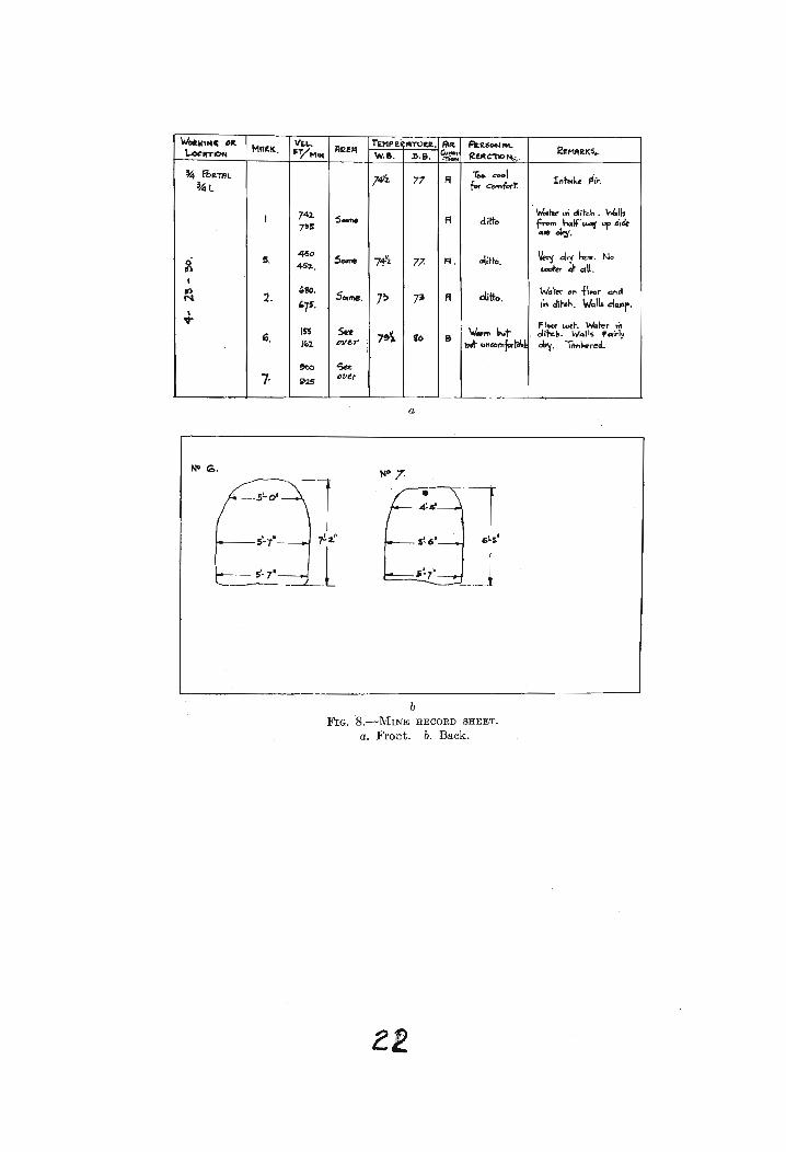
~K"'~~ M.MA'lK.
Vu..RR1R
TEMP ali ATOU. Alit FtftSON ......~M"~I(~~WTIOM FYM'~ w.e. . .%).&. ~,
R~c-no~_.·-nON
~ ~TRL 7.tf4 77 R Too c:'001 Inbek. pflio:~L for Comfort
74 1. W.tat-,"'.olit'c:.n. ~I"I s....,. A ditto f"'''' hdit'AMi "'P .,Ik7'5 ~.~..
5.450
Same 7~2. 77- Fl. ~i~~o.Vef4! .dl'y hv.. No
~ .462. • ~CI~dll •
•Wd~er Cf' ~\oor <1ft,)tt) ,'o.
SOl~. 7~ R ditto.N 2.'75•
7~ .n di~h. WQII. dClJlr.I~ FIocr wet-. ~foe.r \n
'- '" Sf!f7~'). to e \J.,.,.. b~t , di~". w.ll$ FQifl~
)(01, eJley : ,,;to ~",co",~~a~. ~. 1iM~red.I
~ ~e
7· i>2Sollt.r
a
NO to.N° 7-'-1
7!'Z.rt G!.S"
.l .J
bFIG. 8.-MINE RECORD SHEET.
a. Front. b. Back.

gives a relative value which will show an increase or
decrease in volume, as the case may be.
Width and height are measured at desirable
cross-sections in the drifts. These measurements are
plotted and their area round by a planimeter. The
positions are numbered, their number-s being marked on
the wall of the drift or side of the raise, and are called
·ventilation stations; each is marked on a profile of the
mine workings, the directions of the air currents being
also indicated. This profile is kept up to date, showing
all raises, stopes and drirts in the mine that are impor-
tant with respect to ventilation.
Fig. 8 is a copy of a mine record sheet.
Separate sheets are used for each set of readings.
When computing the exhausting powe~ of the
main fan more careful observations are taken. The
anemometer is operated from a rod 3 ft. 6 in. long,
the clutch of the instrument being manipulated by the
observer by means or wires reaching rrom the instrument
to the handle of the rod. 5
Conclusions
After observ'ing the ventilation in this mine,
the writer feels qualified to make the following sugges-
tions:
1. To spend. a large sum of money to make a fewI
main drifts~eool will not give e£ficlent ventilation and
certainly will not justify the cost.

2. To ventilate stapes two openings must be
maintained, one on the high-pressure and one on the
low~pressure side, so that the air will circulate.
This may seem obvious, but its importance often 1s not
appreciated.
3. To be effective the canvas tube that
delivers .air ~rom a .~mall fan or blower to the face
must be kept free rrom kinks, free from leaks and its
end within 25 ft. from the workers that it is meant to
serve.
It 1s regretted that no temperatures were
taken in the mine before the 33,OOO-eu. ft. fan was
moved from 3/4 leval portal to the present ran site on
Tablon. Records were not taken because the old system
was obviously 8'0 wrong tha t there was. no doubt in the
management's mind that the ohange would be for the better.
A record was made, however, of the temperatures in the
mine (April, 1929) ,soon after the fan was moved. Temper
atureswere again taken at similar positions in the mine
after the 33,OOO-cu. ft. fan had been replaced by a
60,OOO-cu. ft. fan.
These comparative temperatures are given in
Table 4. The location of the various ventilation stations ,"
is shown in Fig. 1. The'most apparent drops in temperature
are at No.5, a main haulageway, where the drop was from
24-

TA.BLE 4.-Temperatures Recorded in the Portovelo ...7\!,inesSee Fig. 1 for Positions of Stations
Difference
n.1ay, 1930i April, 1929 I'1
_--
1Stations! ., DrY-bul~ ~ I 'Vet-bulb Dry-bulbI 1 emp., Deo . F. II Temp., Deg. F. Temp., Deg. F. II II 11 _
__~ ~ ~~ I_ _ 74>~ . 1--8o>L-11
-------.-
___2__ 83 i ~~72_-I.---~~~- ~>'2 . ._
---:-_. 84 1-~~---J--~~--1==-2~~=__5 ~~ 74?/§ I, 747~ 1 1_2% __
6 80 75:~ I 75}/~ 4~/2
86
-----_·------1/------- -------1------
~~ :~ II ~~H ~~>2 II 1~>2
25

a dry-bulb temperature of 87~ to 74.5° Fe; at No.8,
the main return air course from the lower levels, where
the drop was from S8 Q to 83~ Fe; at No. 10, a main
split of fresh air to working stopes, where the drop
was from 87° to 75° F. These comparisons serve to show
the change in air temperature in the mine and emphasize
the necessity of air splits.
The writer does not wish to convey the idea
that these temperature drops are entirely due to changing
the mine from a pressure to an exhaust s1stem. He does,
however, contend that in the circumstances an exhaust
system, in conjunction with more openings in the mine and
more air splits, is responsible for the improvement that
is so apparent over conditions of a year ago e
Acknowledgments
The writer is indebted to W. B. Phelps,
General Superintendent of the South American Development
Co. a~ Portovelo, Ecuador, for his kind assistance and
helpful criticism; to Luther Yantis, Chief Engineer of
the South American Development Co. at Portovelo, Ecuador,
:ror helpful criticisms and the use of the company's maps
and drawings in the preparation of this report, and to the
South America.n Development Co. :for providing the opportunity
to study the ventilation problems ·at the mine.

Bibliography
1.- P. Billingsley:- Geology of the Zaruma District of
Ecuador Tran: AI1ill (1926) 74,255
2.- R. Emmel:- Mining Methods in Zaruma District, Ecuador
Tran: AI1ffi (1925) 72,447
3.- W. S. Weeks:- Ventilation of Mines 122, New York, 1926
McGraw-Hill Book Co. Inc.
4.- W. H. Carrier:- Fan Engineering, Ed. I. Buffalo, 1914
BTIrfalo Forge Co.
5.- G. E. McElroy:- Why, When, ·and How to Make Ventilation
Surveys or Metal Mines
U. S. Bur. Mines Circular 6086, 1928