Velocity Triangle for Turbo-machinery BY P M V Subbarao Professor Mechanical Engineering Department...
27
Velocity Triangle for Turbo- machinery BY P M V Subbarao Professor Mechanical Engineering Department I I T Delhi
-
Upload
jaime-martell -
Category
Documents
-
view
219 -
download
2
Transcript of Velocity Triangle for Turbo-machinery BY P M V Subbarao Professor Mechanical Engineering Department...

Velocity Triangle for Turbo-machinery
BY
P M V SubbaraoProfessor
Mechanical Engineering DepartmentI I T Delhi


U
Vri
Vre
Vai
UVri
Vai
Inlet Velocity Triangle
U
VreVae
Exit Velocity Triangle
U
VriVai
Vre
Vae
iie e
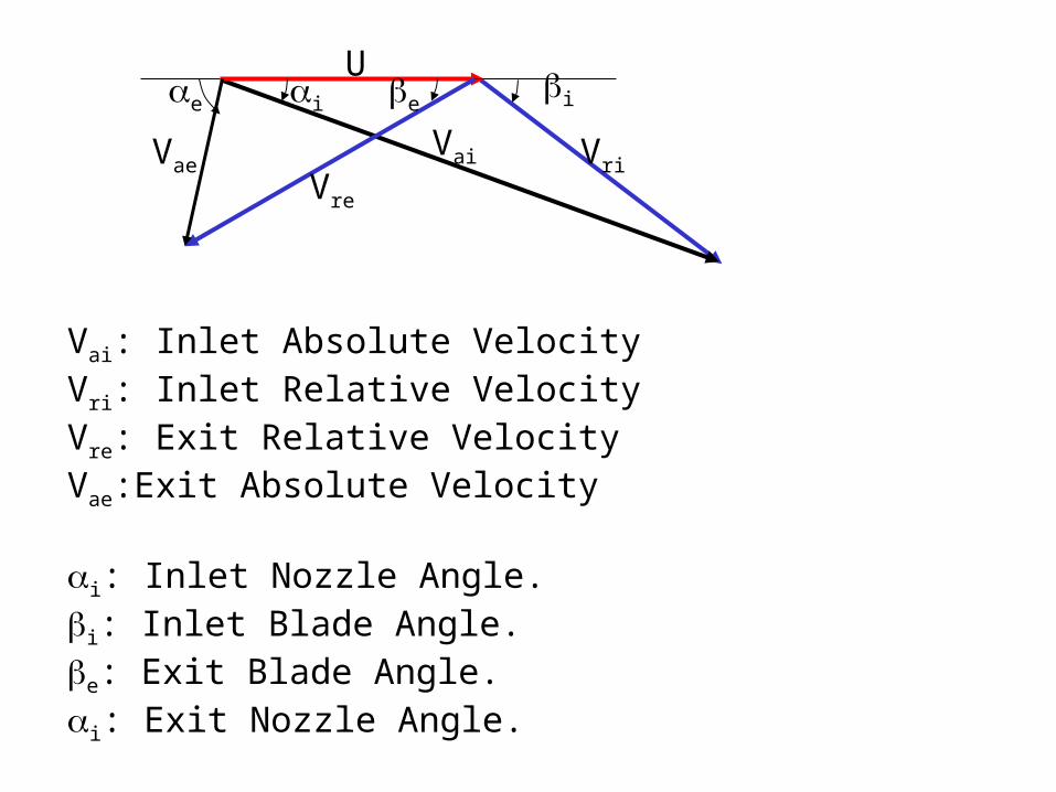
Vai: Inlet Absolute VelocityVri: Inlet Relative VelocityVre: Exit Relative VelocityVae:Exit Absolute Velocity
i: Inlet Nozzle Angle.i: Inlet Blade Angle.e: Exit Blade Angle.i: Exit Nozzle Angle.

Va
Vr
Vrc
Vw
U
Vf

U
U
U
Vri
Vre
Vai
VaeVni
Flow through Blades

Fluid Dynamics of Blades

• The stream is delivered to the wheel at an angle i and velocity Vai.
• The selection of angle i is a compromise.
• An increase in i, reduces the value of useful component (Absolute circumferential Component).
• This is also called Inlet Whirl Velocity, Vwi = Vai cos(i).
• An increase in i, increases the value of axial component, also called as flow component.
• This is responsible for definite mass flow rate between to successive blade.
• Flow component Vfi = Vai sin(i) = Vri sin(i).
• The absolute inlet velocity can be considered as a resultant of blade velocity and inlet relative velocity.
• The two points of interest are those at the inlet and exit of the blade.
U
VriVai
Vre
Vae
iie e
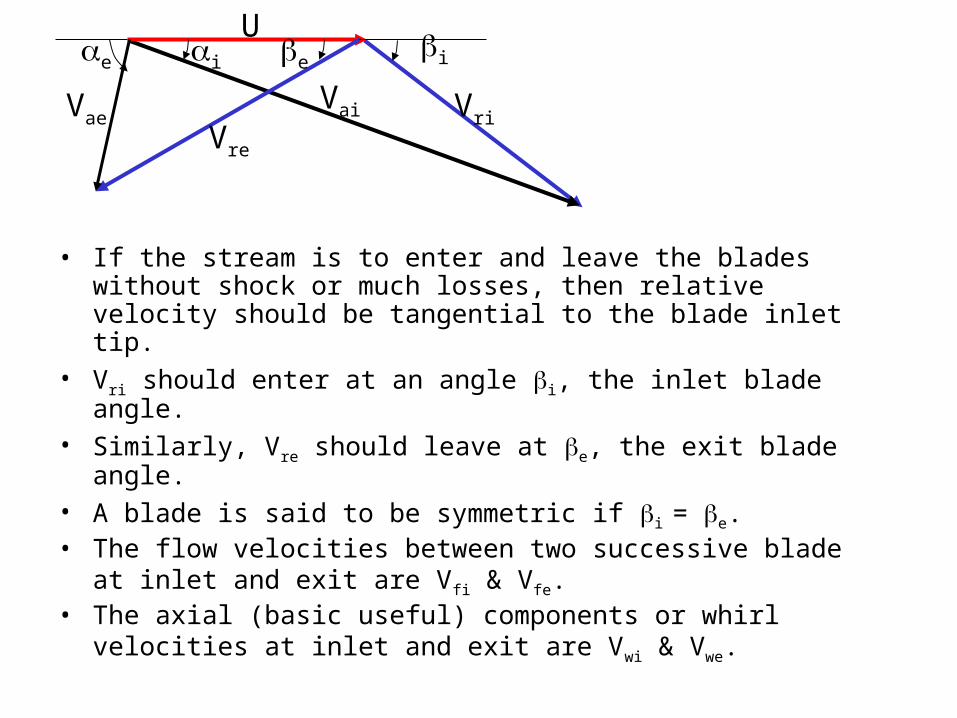
• If the stream is to enter and leave the blades without shock or much losses, then relative velocity should be tangential to the blade inlet tip.
• Vri should enter at an angle i, the inlet blade angle.• Similarly, Vre should leave at e, the exit blade angle.• A blade is said to be symmetric if i = e.• The flow velocities between two successive blade at inlet and exit are
Vfi & Vfe.• The axial (basic useful) components or whirl velocities at inlet and
exit are Vwi & Vwe.
U
VriVai
Vre
Vae
iie e
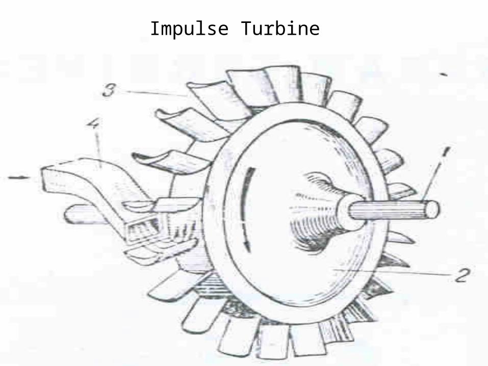
Impulse Turbine

Newton’s Second Law for an Impulse Blade:The tangential force acting of the jet is:F = mass flow rate X Change of velocity in the tangential direction
Tangential relative velocity at blade Inlet : Vri cos(i).
Tangential relative velocity at blade exit : -Vre cos(e).
Change in velocity in tangential direction: -Vre cos(e) - Vri cos(i).
-(Vre cos(e) + Vri cos(i)).
Tanential Force,
U
VriVai
Vre
Vae
iie e
iriereA VVmF coscos

The reaction to this force provides the driving thrust on the wheel.
The driving force on wheel iriereR VVmF coscos
Power Output of the blade,
iriereb VVUmP coscos
Diagram Efficiency or Blade efficiency:
steaminlet ofPower Kinetic
ouputPower d
2
coscos
2ai
riered
Vm
iVVUm
2
coscos2
ai
rierid V
iVkVU
2
coscos2
ai
erid V
ikUV
U
VriVai
Vre
Vae
iie e
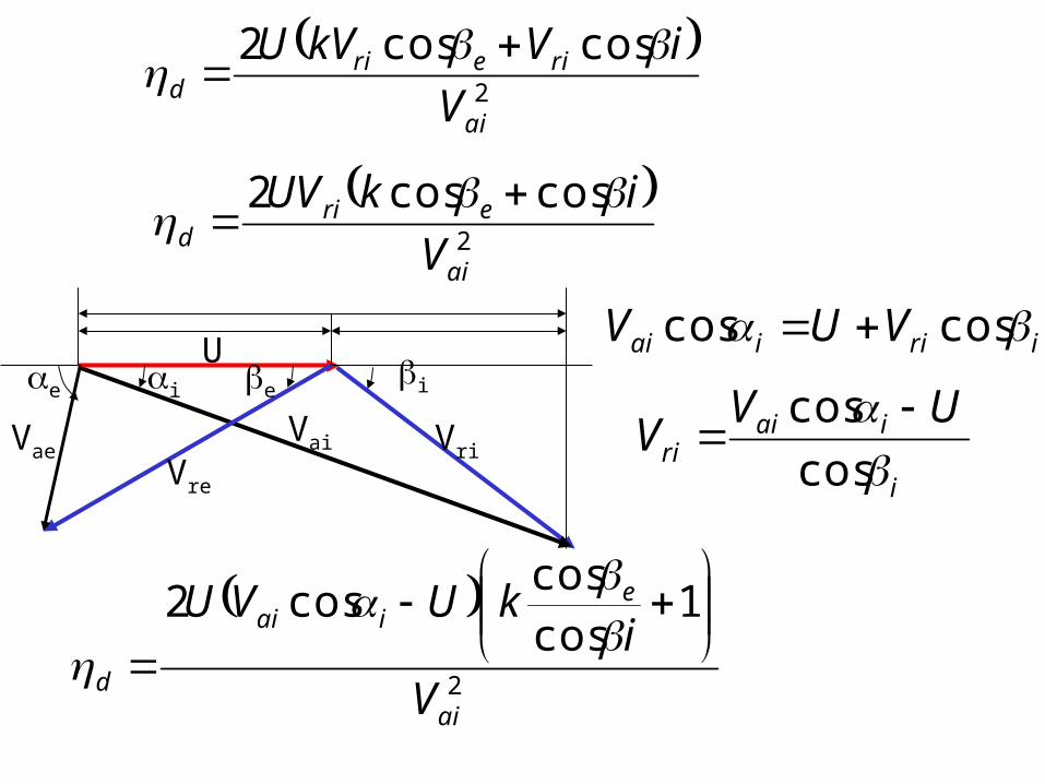
iriiai VUV coscos
i
iairi
UVV
cos
cos
2
1coscos
cos2
ai
eiai
d V
ikUVU

1
cos
coscos2
2
eaii
aid i
kV
U
V
U
2
1coscos
cos2
ai
eiai
d V
ikUVU
Define Blade Speed Ratio,
1
cos
coscos2
ik e
id

For a given shape of the blade, the efficiency is a strong function of
For maximum efficiency: 0
d
d d
01cos
cos2cos2
i
k ei
2
cos02cos i
i
1
cos
cos
2
coscoscos2max, i
k eiiid

1
cos
coscos22
max, ik e
id

Impulse-Reaction turbine
• This utilizes the principle of impulse and reaction.
• There are a number of rows of moving blades attached to the rotor and equal number of fixed blades attached to the casing.
• The fixed blades are set in a reversed manner compared to the moving blades, and act as nozzles.
• The fixed blade channels are of nozzle shape and there is a comparatively small drop in pressure accompanied by an increase in velocity.
• The fluid then passes over the moving blades and, as in the pure impulse turbine, a force is exerted on the blades by the fluid.
• There is further drop in pressure as the fluid passes through the moving blades, since moving blade channels are also of nozzle shape.
• The relative velocity increases in the moving blades.

U
VriVai
VreVae
iie e
pva vr
The reaction effect is an addition to impulse effect.
The degree of reaction
stage in the dropenthalpy The
blades moving in the dropenthalpy The

First law for fixed blades:
0 1 22
20
2
101VV
hh
First law for moving blades:
2
21
2
212 rVV
hh r

• If the stream is to enter and leave the blades without shock or much losses, then relative velocity should be tangential to the blade inlet tip.
• Vr1 should enter at an angle 1, the inlet blade angle.
• Similarly, Vr2 should leave at 2, the exit blade angle.
• In an impulse reaction blade, Vr2 > Vr1.
• The flow velocities between two successive blade at inlet and exit are Vf1 & Vf2.
• The axial (basic useful) components or whirl velocities at inlet and exit are Vw1 & Vw2.
U
Vr1Va1
Vr2Va2
112 2
2
21
2
212 rVV
hh r

Newton’s Second Law for an Impulse-reaction Blade:The tangential force acting of the jet is:F = mass flow rate X Change of velocity in the tangential direction
Tangential relative velocity at blade Inlet : Vr1 cos(2).
Tangential relative velocity at blade exit : -Vr2 cos(2).
Change in velocity in tangential direction: -Vr2 cos(2) – Vr1 cos(1).
-(Vr2 cos(2) + Vr1 cos(1)).
Tangential Force, 1122 coscos rrA VVmF
U
Vr1Va1
Vr2Va2
112 2

The reaction to this force provides the driving thrust on the wheel.
The driving force on wheel 1122 coscos rrR VVmF
Power Output of the blade,
1122 coscos rrb VVUmP
Diagram Efficiency or Blade efficiency:
steaminlet ofPower Kinetic
ouputPower d
2
coscos
21
1122
a
rrd
Vm
VVUm

First law for fixed blades:
2
20
2
101VV
hh
First law for moving blades:
2
21
2
212 rVV
hh r
22
21
220
2
2021 rVVVV
hh r
22
21
220
21
202 raVVVV
hh r

stage in the dropenthalpy The
blades moving in the dropenthalpy The
20
21
hh
hh
21
220
21
21
2
20
21
2
2
ra
r
VVVV
VV
hh
hh
r
r
20
21
22
112VVVV arr
20
21
2
112VVVV arr

1111 coscos ra VUV 1
111 cos
cos
UV
V ar
Losses in nozzle, Nozzle blade loss factor,
ison
a
V
V
,
1
exit nozzleat Velocity cIsoentropi
cityinlet velo absolute Actual
2,
1122 coscos2
ison
rrstage V
VVU
20
21
2
112VVVV arr
21
1122 coscos2
a
rrd V
VVU

21
1122
021
22 coscos1
21
a
ra
stage V
VVVVUr
1
111 cos
cos
UV
V ar
21
11
112
20
21
2
1
112 coscoscos
cos1cos
cos2
a
aa
a
stage V
UVVV
UVU
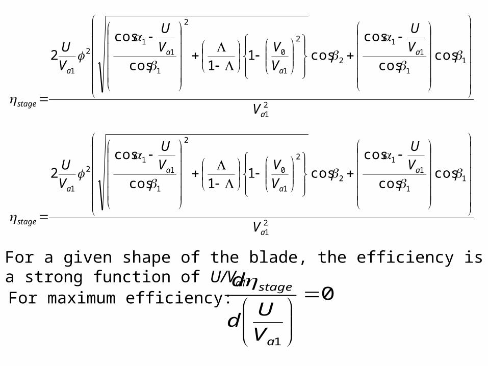
For a given shape of the blade, the efficiency is a strong function of U/Va1
For maximum efficiency: 0
1
a
stage
VU
d
d
21
11
11
2
2
1
0
2
1
11
2
1
coscos
coscos1
1cos
cos2
a
a
a
a
a
stage V
VU
VVV
U
VU
21
11
11
2
2
1
0
2
1
11
2
1
coscos
coscos1
1cos
cos2
a
a
a
a
a
stage V
VU
VVV
U
VU