Velocity Control of Bimodal-tram using Sliding Mode ...
6
Velocity Control of Bimodal-tram using Sliding Mode Control with Anti-Windup Scheme Yeun-Sub Byun, Min-Soo Kim, Jai-Kyun Mok and Young-Chol Kim* Korea Railroad Research Institute 360-1, Woram-dong, Uiwang-si, KOREA * Department of Electronics, Chungbuk National University Abstract: - In this paper, we propose the velocity controller of bimodal tram. The Korea Rail road Research Institute (KRRI) is developing the bimodal tram. The bimodal tram is all wheel steered single articulated vehicle and will be equipped with the automated control systems. The key technology of the systems is longitudinal and lateral vehicle control algorithm. The longitudinal control is concerned with traction control and brake control of the vehicle and the lateral control is concerned with steering control. First, a longitudinal vehicle model is introduced for traction and brake. Then, a velocity tracking controller is designed based on sliding mode control with anti-windup scheme. The simulation results are shown to illustrate the performance of the proposed velocity control algorithm. Key-Words: - Bimodal Tram, Longitudinal Control, Sliding Mode Control, Anti-windup 1 Introduction The bimodal tram is developed by KRRI since the 2004s [1]. The standard model for development is Phileas [2] developed by APTS in Netherlands. The vehicle will be used in the public transportation system. The bimodal tram has the advantages of both bus and train. Bus system has the advantage of flexibility of the routes delivering passengers to the destination and easy accessibility. Train is to meet the scheduled arrival and massive public transportations. The vehicle is the rubber tired tram and has all wheels steered and single articulation. Thus, the vehicle has a small turning radius. The length of the vehicle is 18m. The vehicle lanes will be marked with permanent magnets that are buried in the road. The permanent magnets yield position information exclusively. The vehicle can be automatically operated by navigation control system (NCS). The NCS is responsible for the automatic driving for traction, braking, and steering. The propulsion system of the vehicle uses induction motors and inverters for each of the wheels, except for the two wheels at the front. Thus, propulsion system of the vehicle has the torque limit according to the vehicle speed. In the presence of saturation of actuator, controller using an integral action has some problems like as increasing command input, large overshoot of control response [7]. In this paper, we propose the longitudinal vehicle model of the bimodal tram and the velocity tracking controller which tracks a desired velocity reference. The longitudinal controller is designed based on sliding mode control with anti-windup scheme. Numerical simulation is presented to validate the effectiveness of the designed controller. Fig.1 Small scale model of Korea bimodal tram 2 Longitudinal Model of Bimodal Tram A mathematical model was introduced for longitudinal dynamics of the bimodal tram in order to support the Proceedings of the 7th WSEAS International Conference on CIRCUITS, SYSTEMS, ELECTRONICS, CONTROL and SIGNAL PROCESSING (CSECS'08) ISSN: 1790-5117 237 ISBN: 978-960-474-035-2
Transcript of Velocity Control of Bimodal-tram using Sliding Mode ...

Velocity Control of Bimodal-tram using Sliding Mode Control with Anti-Windup Scheme
Yeun-Sub Byun, Min-Soo Kim, Jai-Kyun Mok and Young-Chol Kim*
Korea Railroad Research Institute 360-1, Woram-dong, Uiwang-si,
KOREA * Department of Electronics, Chungbuk National University
Abstract: - In this paper, we propose the velocity controller of bimodal tram. The Korea Rail road Research Institute (KRRI) is developing the bimodal tram. The bimodal tram is all wheel steered single articulated vehicle and will be equipped with the automated control systems. The key technology of the systems is longitudinal and lateral vehicle control algorithm. The longitudinal control is concerned with traction control and brake control of the vehicle and the lateral control is concerned with steering control. First, a longitudinal vehicle model is introduced for traction and brake. Then, a velocity tracking controller is designed based on sliding mode control with anti-windup scheme. The simulation results are shown to illustrate the performance of the proposed velocity control algorithm. Key-Words: - Bimodal Tram, Longitudinal Control, Sliding Mode Control, Anti-windup 1 Introduction The bimodal tram is developed by KRRI since the 2004s [1]. The standard model for development is Phileas [2] developed by APTS in Netherlands. The vehicle will be used in the public transportation system. The bimodal tram has the advantages of both bus and train. Bus system has the advantage of flexibility of the routes delivering passengers to the destination and easy accessibility. Train is to meet the scheduled arrival and massive public transportations.
The vehicle is the rubber tired tram and has all wheels steered and single articulation. Thus, the vehicle has a small turning radius. The length of the vehicle is 18m. The vehicle lanes will be marked with permanent magnets that are buried in the road. The permanent magnets yield position information exclusively.
The vehicle can be automatically operated by navigation control system (NCS). The NCS is responsible for the automatic driving for traction, braking, and steering. The propulsion system of the vehicle uses induction motors and inverters for each of the wheels, except for the two wheels at the front. Thus, propulsion system of the vehicle has the torque limit according to the vehicle speed. In the presence of
saturation of actuator, controller using an integral action has some problems like as increasing command input, large overshoot of control response [7].
In this paper, we propose the longitudinal vehicle model of the bimodal tram and the velocity tracking controller which tracks a desired velocity reference. The longitudinal controller is designed based on sliding mode control with anti-windup scheme. Numerical simulation is presented to validate the effectiveness of the designed controller.
Fig.1 Small scale model of Korea bimodal tram 2 Longitudinal Model of Bimodal Tram A mathematical model was introduced for longitudinal dynamics of the bimodal tram in order to support the
Proceedings of the 7th WSEAS International Conference on CIRCUITS, SYSTEMS, ELECTRONICS, CONTROL and SIGNAL PROCESSING (CSECS'08)
ISSN: 1790-5117 237 ISBN: 978-960-474-035-2

development of the velocity controller. The model has to capture enough dynamic characteristics, and to be simple enough for real time applications. Though the bimodal tram has an articulation, the model is similar to a bus model except for minor differences [3]. Before deriving the longitudinal dynamics of the bimodal tram, we have some assumptions as the followings: 1) No slip between the wheels and ground 2) A symmetric rigid body of vehicle chassis.
Using the assumption above and balancing the forces in longitudinal direction, the longitudinal equation of motion is obtained as [4].
)(/)(
hRJFFFhRTRTT
ve
grabacce
⋅
++⋅−⋅−−=& (1)
θsin
2
gmFgmCF
vCF
g
rr
aa
===
)( 22 mhIRIJ wee ++= where v is the velocity of the vehicle, eT is the engine torque, accT is the accessory engine power, R is the gear ratio, bT is the break torque, h is the tire radius,
aF is the aerodynamic drag force, rF is the rolling resistance force, gF is the gradient resistance force, eJ is the effective inertia reflected on the engine side, aC is the aerodynamic drag coefficient, rC is the rolling resistance coefficient, m is the total weight of the vehicle, eI is the inertia of the engine, wI is the overall inertia of the axle, g is the gravity, and θ is the road slope angle.
The propulsion system of the bimodal tram consists of electric motors. The brake system of the bimodal tram is engaged through a combination of electrical and pneumatic braking. But it is possible to brake electrically to nearly a full stop. Thus, if eT is the plus value, the NCS recognizes it to the traction command. If eT is the minus value, the NCS recognizes it to the braking command. Thus, we can rewrite Eq. (1) as follows [8]:
)(/)(
hRJFFFhRT
ve
grae
⋅
++⋅−=& (2)
)( 22 mhIRIJ wee ++=
where v is the velocity of the vehicle, eT is the motor torque, R is the reduction gear ratio, eJ is the effective inertia reflected on the motor side, eI is the inertia of the motor, and wI is the overall inertia of the axle.
Fig. 2 shows the longitudinal motion of the bimodal tram.
Bimodal Tram
mg
aF
θ
rF
rF
rF
v
Fig.2 Longitudinal motion model of bimodal tram 3 Sliding Mode Control with Anti- windup Sliding mode control is one of the useful nonlinear robust control approaches [5]. The control strategy is derived in the sense of Lyapunov stability theorem. We will use the sliding mode control (SMC) scheme [6]. To apply the SMC, we will rearrange Eq. (2) to apply the sliding mode control as follows:
)()()(
)()(
222
2
vCvCFFJhRT
JhRvC
JhR
TJ
hRFFF
JhR
v
aagre
ee
ae
ee
grae
+−+−+−=
+++−=& (3)
Le
ee
ae
TJhRT
JhRvC
JhRv
22 )()(−+−=& (4)
The longitudinal dynamic of the bimodal tram can be represented to apply the sliding mode control as follows:
Lppp TCtUBtXAtX ++= )()()(& (5)
2vCvCFFT aagrL +−+= (6)
where vtX =)( , eap JCRhA /)( 2−= , ep JhRB /)(= ,
ep JhRC /)( 2−= , and )(tU is the control effort.
Now, we will define the nominal model of the bimodal tram as follows:
)()()( tUBtXAtX pnpn +=& (7)
Proceedings of the 7th WSEAS International Conference on CIRCUITS, SYSTEMS, ELECTRONICS, CONTROL and SIGNAL PROCESSING (CSECS'08)
ISSN: 1790-5117 238 ISBN: 978-960-474-035-2

where epneapn JhRBJChRA /)(,/)( 2 =−= .
Define a reference model to specify the desired behavior of the controlled system as
)()()( tUBtXAtX mmmmm +=& . (8)
Let e denote the speed error between the reference model and the actual speed as follows:
)()()( tXtXte m −= . (9)
Define a sliding surface with integral limit of error as
)0()()),(()()( 0max edzzeUtULimtetS tB −∫⋅+= β (10)
where ⎩⎨⎧
>≤
=max
maxmax )(0
)(1)),((
UtUifUtUif
UtULim .
)),(( maxUtULim
maxU )(tU
Fig. 3 Limit function
Thus, an equivalent control law can be designed as
)]()()(
)0()()()([)( 01
tUBtXAA
eAdzzeABtU
mmpnm
mt
mpnea
+−+
++∫+−= − βββ (11)
))](sgn()([)( 1 tSKtSKBtU bapns ββ += − (12) where
⎩⎨⎧
<−≥+
=0)(10)(1
))(sgn(tSiftSif
tSβ
ββ .
))(sgn( tSβ
)(tSβ)(tSβ−
Fig. 4 Sign function
The final control law can be designed as
)()()( tUtUtU sea += (13) ),)(()( maxUtUsattUc =
where
⎩⎨⎧
≥<
=maxmax
maxmax )(
)()()),((
UtUifUUtUiftU
UtUsat .
1
-1
)(tUmaxU
maxU−
)),(( maxUtUsat
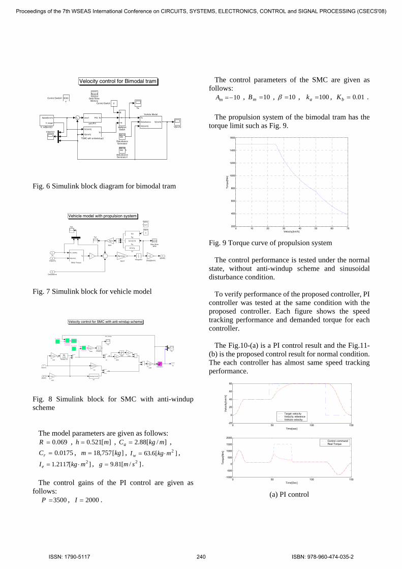
Fig. 5 Saturation function 4 Simulation using MATLAB/ SIMULINK Simulations are carried out to verify the feasibility of the proposed control system using the Matlab/Simulink simulation environment. The simulink model of total block diagram is shown in Fig. 6. Figure 7 shows the block diagram for the vehicle model including a propulsion system. Figure 8 shows the block diagram for SMC including the anti-windup scheme.
Proceedings of the 7th WSEAS International Conference on CIRCUITS, SYSTEMS, ELECTRONICS, CONTROL and SIGNAL PROCESSING (CSECS'08)
ISSN: 1790-5117 239 ISBN: 978-960-474-035-2
Velocity control for Bimodal tram
error1 PID_Te
anti-PI1
Te
Disturbance
Vtr[km/h]
V[km/h]
Vehicle Model
Speed[km/h]
V_target
V_ref[km/h]1
V[km/h]1
V[km/h]
Te
Vr[km/h]
V[km/h]Te
TSMC with antiwindup2
MultiportSwitch
DisturbanceGenerator1
DisturbanceGenerator
Speed
Data StoreMemory
3000Control Switch1
2Control Switch
Fig. 6 Simulink block diagram for bimodal tram
Vehicle model with propulsion system
1V[km/h]
0.61
degree1
0
degree
3.6
[m/s]2[km/h]
Te2
Te1
Tm_ref[Nm]
Vtr[km/h]
Te
Motor Torque
1s
Integrator
(Rg*h)/Je
Gain1
Rg*h
Gain
Cr*m*g
Fr
f(u)
Fg
Ca*u[1]^2
Fa
Speed
Data StoreWrite
1
3
Vtr[km/h]
2
Disturbance
1
Te
Fig. 7 Simulink block for vehicle model
Xt
Velocity control for SMC with anti-windup scheme
1Te
(Am-Apn)*u[1]
m1
1/Bpn
Um8
1/3.6
Um7
Kb
Um4Ka
Um3
beta
Um2
1/3.6
Um1
Bm/3.6
Um
Bm
s-Am
Transfer Fcn
1
Te_max2
1500
Te_max1
Te2
Te1
Sign
Saturation
<=
RelationalOperator
Product3
1s
Integrator
(double)
2V[km/h]
1Vr[km/h]
Anti_windup
Anti_windup
SBXm
Ueq
Fig. 8 Simulink block for SMC with anti-windup scheme
The model parameters are given as follows: 069.0=R , ][521.0 mh = , ]/[88.2 mkgCa = , 0175.0=rC , ][757,18 kgm = , ][6.63 2mkgIw ⋅= ,
][2117.1 2mkgIe ⋅= , ]/[81.9 2smg = . The control gains of the PI control are given as
follows: 3500=P , 2000=I .
The control parameters of the SMC are given as
follows: 10−=mA , 10=mB , 10=β , 100=ak , 01.0=bK .
The propulsion system of the bimodal tram has the
torque limit such as Fig. 9.
0 10 20 30 40 50 60 70200
400
600
800
1000
1200
1400
1600
Velocity[km/h]
Tor
que[
Nm
]
Fig. 9 Torque curve of propulsion system
The control performance is tested under the normal state, without anti-windup scheme and sinusoidal disturbance condition.
To verify performance of the proposed controller, PI
controller was tested at the same condition with the proposed controller. Each figure shows the speed tracking performance and demanded torque for each controller.
The Fig.10-(a) is a PI control result and the Fig.11-
(b) is the proposed control result for normal condition. The each controller has almost same speed tracking performance.
0 50 100 150-20
0
20
40
60
80
Time[sec]
Vel
ocity
[km
/h]
0 50 100 150-1000
-500
0
500
1000
1500
2000
Time[Sec]
Tor
que[
Nm
]
Target velocityVelocity referenceVehicle velocity
Control commandReal Torque
(a) PI control
Proceedings of the 7th WSEAS International Conference on CIRCUITS, SYSTEMS, ELECTRONICS, CONTROL and SIGNAL PROCESSING (CSECS'08)
ISSN: 1790-5117 240 ISBN: 978-960-474-035-2
0 50 100 150-20
0
20
40
60
80
Time[sec]
Vel
ocity
[km
/h]
0 50 100 150-1000
-500
0
500
1000
1500
2000
Time[Sec]
Tor
que[
Nm
]
Target velocityVelocity referenceVehicle velocity
Control commandReal Torque
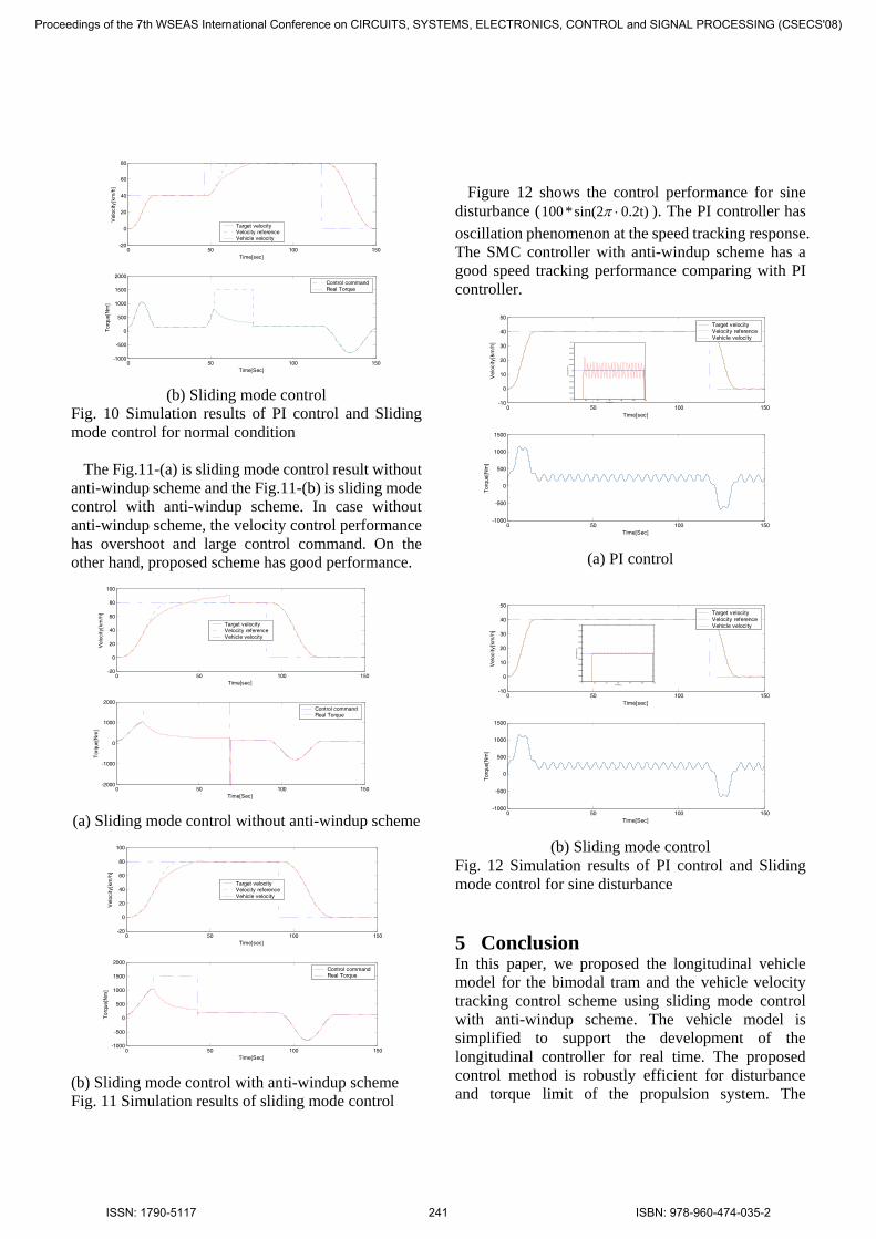
(b) Sliding mode control
Fig. 10 Simulation results of PI control and Sliding mode control for normal condition
The Fig.11-(a) is sliding mode control result without anti-windup scheme and the Fig.11-(b) is sliding mode control with anti-windup scheme. In case without anti-windup scheme, the velocity control performance has overshoot and large control command. On the other hand, proposed scheme has good performance.
0 50 100 150-20
0
20
40
60
80
100
Time[sec]
Vel
ocity
[km
/h]
0 50 100 150-2000
-1000
0
1000
2000
Time[Sec]
Tor
que[
Nm
]
Control commandReal Torque
Target velocityVelocity referenceVehicle velocity
(a) Sliding mode control without anti-windup scheme
0 50 100 150-20
0
20
40
60
80
100
Time[sec]
Vel
ocity
[km
/h]
0 50 100 150-1000
-500
0
500
1000
1500
2000
Time[Sec]
Tor
que[
Nm
]
Target velocityVelocity referenceVehicle velocity
Control commandReal Torque
(b) Sliding mode control with anti-windup scheme Fig. 11 Simulation results of sliding mode control
Figure 12 shows the control performance for sine disturbance ( 0.2t)sin(2*100 ⋅π ). The PI controller has oscillation phenomenon at the speed tracking response. The SMC controller with anti-windup scheme has a good speed tracking performance comparing with PI controller.
0 50 100 150-10
0
10
20
30
40
50
Time[sec]
Vel
ocity
[km
/h]
0 50 100 150-1000
-500
0
500
1000
1500
Time[Sec]
Tor
que[
Nm
]
Target velocityVelocity referenceVehicle velocity
0 20 40 60 80 100 12039.9
39.92
39.94
39.96
39.98
40
40.02
40.04
40.06
40.08
40.1
Time[sec]
Vel
ocity
[km
/h]
(a) PI control
0 50 100 150-10
0
10
20
30
40
50
Time[sec]
Vel
ocity
[km
/h]
0 50 100 150-1000
-500
0
500
1000
1500
Time[Sec]
Tor
que[
Nm
]
Target velocityVelocity referenceVehicle velocity
0 20 40 60 80 100 12039.9
39.92
39.94
39.96
39.98
40
40.02
40.04
40.06
40.08
40.1
Time[sec]
Vel
ocity
[km
/h]
(b) Sliding mode control
Fig. 12 Simulation results of PI control and Sliding mode control for sine disturbance 5 Conclusion In this paper, we proposed the longitudinal vehicle model for the bimodal tram and the vehicle velocity tracking control scheme using sliding mode control with anti-windup scheme. The vehicle model is simplified to support the development of the longitudinal controller for real time. The proposed control method is robustly efficient for disturbance and torque limit of the propulsion system. The
Proceedings of the 7th WSEAS International Conference on CIRCUITS, SYSTEMS, ELECTRONICS, CONTROL and SIGNAL PROCESSING (CSECS'08)
ISSN: 1790-5117 241 ISBN: 978-960-474-035-2

simulation results show that the proposed controller has good performance compared with classic PI controller under the several conditions. References: [1] Jai-Kyun Mok, Development of Fuel Cell Rubber
Tired Tram, Rep, 2006. [2] Advanced Public Transport Systems BV,
http://www.sre.nl/hov. [3] Demonstration of Automated Heavy-Duty
Vehicles, California PATH Tech. Rep., 2006. [4] Drive/brake master tests on 18m workhorse
23/8/2001 and 30/8/2001, APTS. 2001. [5] V. I. Utkin, Sliding mod control design principle
and application to electric drives, IEEE Trans. Ind. Electron., Vol.40, 1993, pp 23-36.
[6] Rong-Jong Wai, Kuo-Min Lin, Chung-You Lin, Total sliding-mode speed control of field-oriented induction motor servo drive, 5th Asian Control Conference 2004, Vol. 2, 20-23 July, 2004, pp.1354-1361.
[7] Chang, P. H., Park, S. H., and Lee, S. U., Development of Anti-Windup Method for Time Delay Control, Trans. of the Korea Society of Mechanical Eng., Vol. 18. No. 10, 1994, pp. 2616-2628.
[8] Yeun-Sub Byun et al. 3, Longitudinal Control of Bimodal-tram using Sliding Mode Control, Proc. Of ICCAS 2008, Seoul, Korea, 2008.
Proceedings of the 7th WSEAS International Conference on CIRCUITS, SYSTEMS, ELECTRONICS, CONTROL and SIGNAL PROCESSING (CSECS'08)
ISSN: 1790-5117 242 ISBN: 978-960-474-035-2