Vel-Max Vessel Manual - Velcon · VEL1970R5 1015 Effective: October 2015 Vel-Max® Vessel Manual...
36
VEL1970R5 1015 Effective: October 2015 Vel-Max ® Vessel Manual Parker Hannifin Corporation Hydraulic & Fuel Filtration Division 1210 Garden of the Gods Road Colorado Springs, CO 80907 +1 719 531 5855 Phone +1 719 531 5690 Fax www.velcon.com [email protected]
Transcript of Vel-Max Vessel Manual - Velcon · VEL1970R5 1015 Effective: October 2015 Vel-Max® Vessel Manual...
VEL1970R5 1015
Effective: October 2015
Vel-Max® Vessel Manual
Parker Hannifi n CorporationHydraulic & Fuel Filtration Division
1210 Garden of the Gods RoadColorado Springs, CO 80907+1 719 531 5855 Phone+1 719 531 5690 [email protected]


3 Parker Hannifi n CorporationHydraulic & Fuel Filtration DivisionColorado Springs, CO 80907 USA
Hydraulic & Fuel Filtration DivisionVel-Max Vessel Manual
VEL1970R5 1015
TABLE OF CONTENTS
GENERAL DESCRIPTION ........................................................................................................................................ 5
INSTALLATION OF VESSEL ..................................................................................................................................... 5
VEL-MAX CONFIGURATIONS KITS ......................................................................................................................... 5
START-UP PROCEDURE (VESSEL ON PRESSURE SIDE OF CENTRIFUGAL PUMP) ............................................ 6
START-UP PROCEDURE (VESSEL ON SUCTION SIDE OF PUMP) ........................................................................ 6
FILTER/SEPARATOR ............................................................................................................................................... 7
DESCRIPTION ....................................................................................................................................................... 7
FILTER/SEPARATOR CARTRIDGE INSTALLATION ............................................................................................... 7
FUEL MONITOR USING CDF® CARTRIDGES ........................................................................................................ 8
DESCRIPTION ....................................................................................................................................................... 8
CDF MONITOR CARTRIDGE INSTALLATION ....................................................................................................... 8
CLAY TREATER ....................................................................................................................................................... 8
DESCRIPTION ....................................................................................................................................................... 8
LA-61801B CLAY TREATER CANISTER INSTALLATION ...................................................................................... 8
FUEL MONITOR USING AVIATION AQUACON® CARTRIDGES (6” OD) ................................................................ 9
DESCRIPTION ....................................................................................................................................................... 9
AQUACON MONITOR CARTRIDGE INSTALLATION ............................................................................................ 9
INDUSTRIAL PREFILTER (6-1/4” OD) ................................................................................................................... 10
DESCRIPTION ..................................................................................................................................................... 10
FO-7XXXX PREFILTER CARTRIDGE INSTALLATION ......................................................................................... 10
AVIATION PREFILTER (6” OD) ................................................................................................................................ 10
DESCRIPTION ..................................................................................................................................................... 10
FO-6XXXX PREFILTER CARTRIDGE INSTALLATION ......................................................................................... 10
FUEL MONITOR USING INDUSTRIAL AQUACON CARTRIDGES (6-1/4” OD) ..................................................... 11
DESCRIPTION ..................................................................................................................................................... 11
INDUSTRIAL AQUACON MONITOR CARTRIDGE INSTALLATION .................................................................... 11
TABLE OF CONTENTS

4 Parker Hannifi n CorporationHydraulic & Fuel Filtration DivisionColorado Springs, CO 80907 USA
Hydraulic & Fuel Filtration DivisionVel-Max Vessel Manual
VEL1970R5 1015
TABLE OF CONTENTS
APPENDIX
FIGURE 1: FILTER/SEPARATOR CONFIGURATION ...............................................................................................14
FIGURE 2: CDF MONITOR CONFIGURATION ........................................................................................................15
FIGURE 3: 6” OR 6.25” OD X 2.625” ID CONFIGURATION ....................................................................................16
FIGURE 4: 6” OD X 3.5” ID CONFIGURATION........................................................................................................17
VEL-MAX® DATA SHEET (FORM VEL1961) ...................................................................................................... 18-21
SEPARATOR CARTRIDGE DATA SHEET (FORM VEL1521) .............................................................................. 21-22
PLEATED MEDIA FILTER CARTRIDGE DATA SHEET (FORM VEL1549) ........................................................... 23-24
INDUSTRIAL AQUACON® CARTRIDGE DATA SHEET (FORM 1582) ................................................................ 25-26
ADSORBENT CARTRIDGE DATA SHEET (FORM VEL1667) ............................................................................. 27-28
ACO AQUACON® CARTRIDGE DATA SHEET (FORM VEL1681) ...................................................................... 29-30
CDF® P SERIES (FORM VEL1962) .................................................................................................................... 31-32
SYNTHETIC MEDIA (FORM VEL1734) .............................................................................................................. 33-34
OPERATING PROCEDURES FOR WATER ABSORBING CARTRIDGES (FORM VEL1839).............................. 35-36

5 Parker Hannifi n CorporationHydraulic & Fuel Filtration DivisionColorado Springs, CO 80907 USA
Hydraulic & Fuel Filtration DivisionVel-Max Vessel Manual
VEL1970R5 1015
GENERAL DESCRIPTION
The Parker Velcon Vel-Max® vessel that you have received consists of the vessel and accessory equipment to meet your specific requirements. Descriptive literature covering the accessories is included near the back of this manual.
A variety of filter cartridges, and associated hardware kits, can be used with this vessel.
The Vel-Max vessel can be configured in 4 different ways. These are:
Prefilter vessel for particle removal
Filter/separator for both water and particle removal
Fuel monitor utilizing patented Aquacon or CDF
cartridges
Clay treater, for surfactant removal
Each of these configurations are discussed in more detail following. See the specific section covering your configuration for cartridge installation, startup procedures, operating information, cartridge change-out, and other necessary information.
INSTALLATION OF VESSEL
1. Identify the vessel inlet and outlet by the markings provided on the vessel piping connections. The inlet is near the top opening of the vessel; the outlet is at the bottom of the vessel. The vessel must be installed in the correct fl ow direction to perform properly and to avoid damage to the system. (Note: some fi lter cartridges fl ow opposite the normal fl ow direction. ADI cartridges require inlet fl ow to enter at the bottom of the vessel.)
2. Inlet and outlet piping should be carefully aligned to avoid stressing the vessel connections during installation. Installation of shut-off valves on both sides of the vessel is recommended to ease cartridge changeout or vessel inspection.
CAUTION
STEPS 3 AND 4 SHOULD BE PER-FORMED BEFORE REMOVING HINGED COVER TO INSURE STABILITY OF THE VESSEL
3. Insure that the leg assembly is bolted snugly to the vessel body.
4. Bolt the legs to a stable, horizontal base.
5. Adjust the vessel body to the necessary height, if required, by loosening the leg assembly and retightening after required vessel location has been achieved.
6. Thread appropriate fi ttings to the inlet and outlet connections. Use pipe dope or Tefl on® thread to seal the threaded connections.
7. Connect any accessories that are not already installed. See Accessory Parts List and literature as required.
8. Cartridges are normally packed separately. Refer to the appropriate section for the confi guration that you have purchased.
NOTE THE VESSEL MUST BE PROVIDED WITH A PRESSURE RELIEF VALVE IF THE SYSTEM HAS POSITIVE DISPLACEMENT PUMPS UPSTREAM OR AUTOMATIC SHUT-OFF VALVES DOWNSTREAM OF THE VESSEL
VEL-MAX CONFIGURATIONS KITS
The following is a listing of the kits required for each configuration. Make sure that your vessel includes the appropriate conversion kit for your configuration. Kit installation instructions are included with each conversion kit. Install the kit before proceeding.
Configuration VX-1 VX-2 VX-3
FILTER/
SEPARATORVX1-FSKIT VX2-FSKIT VX3-FSKIT
AVIATION
Aquacon (6” OD)VX1-AVKIT VX2-AVKIT VX3-AVKIT
AVIATION
PREFILTER (6” OD)VX1-AVKIT VX2-AVKIT VX3-AVKIT
INDUSTRIAL
PREFILTER or
CLAY CARTRIDGE
(6.25” OD)
VX1-INKIT N/A VX3-INKIT
INDUSTRIAL
Aquacon (6.25” OD)VX1-INKIT N/A VX3-INKIT
CDF® CARTRIDGES VX1-CDKIT VX2-CDKIT N/A
6 Parker Hannifi n CorporationHydraulic & Fuel Filtration DivisionColorado Springs, CO 80907 USA
Hydraulic & Fuel Filtration DivisionVel-Max Vessel Manual
VEL1970R5 1015
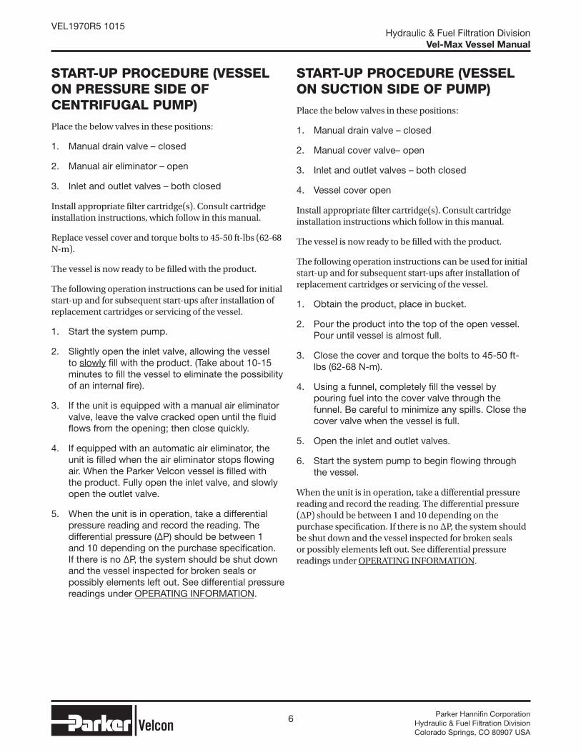
START-UP PROCEDURE (VESSEL ON PRESSURE SIDE OF CENTRIFUGAL PUMP)
Place the below valves in these positions:
1. Manual drain valve – closed
2. Manual air eliminator – open
3. Inlet and outlet valves – both closed
Install appropriate filter cartridge(s). Consult cartridge installation instructions, which follow in this manual.
Replace vessel cover and torque bolts to 45-50 ft-lbs (62-68 N-m).
The vessel is now ready to be filled with the product.
The following operation instructions can be used for initial start-up and for subsequent start-ups after installation of replacement cartridges or servicing of the vessel.
1. Start the system pump.
2. Slightly open the inlet valve, allowing the vessel to slowly fi ll with the product. (Take about 10-15 minutes to fi ll the vessel to eliminate the possibility of an internal fi re).
3. If the unit is equipped with a manual air eliminator valve, leave the valve cracked open until the fl uid fl ows from the opening; then close quickly.
4. If equipped with an automatic air eliminator, the unit is fi lled when the air eliminator stops fl owing air. When the Parker Velcon vessel is fi lled with the product. Fully open the inlet valve, and slowly open the outlet valve.
5. When the unit is in operation, take a differential pressure reading and record the reading. The differential pressure (ΔP) should be between 1 and 10 depending on the purchase specifi cation. If there is no ΔP, the system should be shut down and the vessel inspected for broken seals or possibly elements left out. See differential pressure readings under OPERATING INFORMATION.
START-UP PROCEDURE (VESSEL ON SUCTION SIDE OF PUMP)
Place the below valves in these positions:
1. Manual drain valve – closed
2. Manual cover valve– open
3. Inlet and outlet valves – both closed
4. Vessel cover open
Install appropriate filter cartridge(s). Consult cartridge installation instructions which follow in this manual.
The vessel is now ready to be filled with the product.
The following operation instructions can be used for initial start-up and for subsequent start-ups after installation of replacement cartridges or servicing of the vessel.
1. Obtain the product, place in bucket.
2. Pour the product into the top of the open vessel. Pour until vessel is almost full.
3. Close the cover and torque the bolts to 45-50 ft-lbs (62-68 N-m).
4. Using a funnel, completely fi ll the vessel by pouring fuel into the cover valve through the funnel. Be careful to minimize any spills. Close the cover valve when the vessel is full.
5. Open the inlet and outlet valves.
6. Start the system pump to begin fl owing through the vessel.
When the unit is in operation, take a differential pressure reading and record the reading. The differential pressure (ΔP) should be between 1 and 10 depending on the purchase specification. If there is no ΔP, the system should be shut down and the vessel inspected for broken seals or possibly elements left out. See differential pressure readings under OPERATING INFORMATION.

7 Parker Hannifi n CorporationHydraulic & Fuel Filtration DivisionColorado Springs, CO 80907 USA
Hydraulic & Fuel Filtration DivisionVel-Max Vessel Manual
VEL1970R5 1015
FILTER/SEPARATOR
DESCRIPTION
The Parker Velcon Filter/Separator that you have received consists of the vessel, separately purchased first and second stage elements, and accessory equipment to meet your specific requirements. Descriptive literature covering the accessories is included near the back of this manual.
Parker Velcon Filter/Separators are manufactured to meet a variety of different end uses and specifications. The finest workmanship has gone into the building of this Parker Velcon Filter/Separator. It is of no value, however, if elements are improperly installed or the unit is improperly operated. We urge you to read the manual carefully and follow the instructions given.
A Parker Velcon Filter/Separator is specifically designed to remove solid contaminants and water from the product. To accomplish this, the Filter/Separator is equipped with two types of cartridges through which the product passes in sequence.
FIRST STAGE COALESCER CARTRIDGES
These cartridges have two functions. They filter solid contaminants out of the product and coalesce water into droplets. Any water present in the influent product is usually emulsified into tiny drops by the action of the pumps handling the product. The first stage cartridges coalesce these tiny drops into drops of sufficient size to settle out of the product rapidly.
SECOND STAGE SEPARATOR CARTRIDGES
The function of the second stage cartridges is to repel coalesced water droplets that have not yet settled so that they are prevented from going downstream with the product.
The water should be drained manually on a daily basis (automatic drain valves are not recommended). Proper provision for drainage of accumulated water is of key importance in the operation of any Filter/Separator. If the water level gets too high, it will be carried downstream.
FILTER/SEPARATOR CARTRIDGE INSTALLATION
SEPARATOR CARTRIDGE
1. Insure the tie rod is securely mounted.
2. Remove the separator cartridge from the packaging. Handle carefully by the end caps.DO NOT TOUCH THE SURFACE OF THE SEPARATOR MEDIA.
3. Install the separator cartridge over the tie rod. Make sure to center the separator on the mount and seat it squarely to achieve a good seal.
4. Install the seal plate, rubber gasket, fl at washer, lock washer, and nut as shown in Figure 1 (Page 14).
5. Torque the nut as illustrated in Figure 1 (Page 14).
COALESCER CARTRIDGE
1. Remove the coalescer cartridge from the packaging.
2. Install the coalescer cartridge over the separator cartridge previously installed. Center the cartridge in the vessel to achieve a good seal.
3. Install the seal plate, rubber gasket, fl at washer, lock washer and nut as shown in Figure 1 (Page 14).
4. Torque the nut as illustrated in Figure 1 (Page 14).
CAUTION
USE ONLY PARKER VELCON CARTRIDGES IN THIS FILTER/SEPARATOR. PARKER HANNIFIN CANNOT WARRANT PERFORMANCE IF ANY OTHER MANUFACTURER’S CARTRIDGES ARE USED.

8 Parker Hannifi n CorporationHydraulic & Fuel Filtration DivisionColorado Springs, CO 80907 USA
Hydraulic & Fuel Filtration DivisionVel-Max Vessel Manual
VEL1970R5 1015
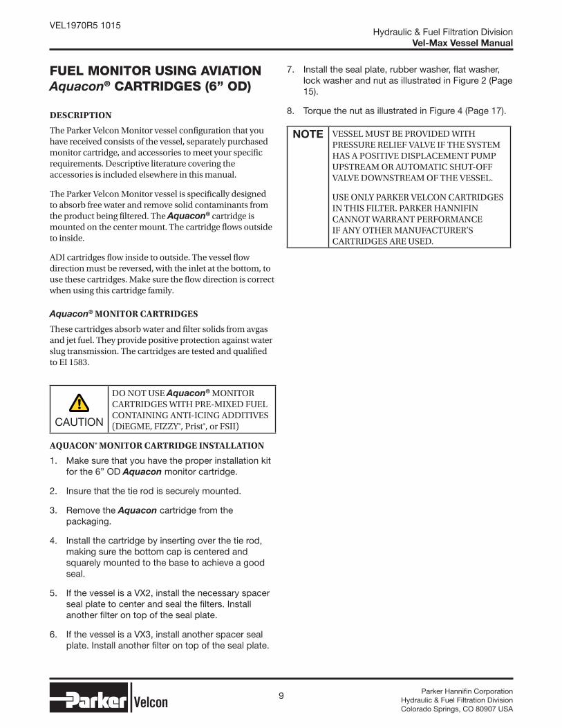
FUEL MONITOR USING CDF® CARTRIDGES
DESCRIPTION
The Parker Velcon Monitor vessel configuration that you have received consists of the vessel, separately purchased monitor cartridges, and accessories to meet your specific requirements. Descriptive literature covering the accessories is included elsewhere in this manual.
The Parker Velcon Monitor vessel is specifically designed to absorb free water and remove solid contaminants from the product being filtered. Five CDF® cartridges are mounted on the adapter. The cartridges flow outside to inside.
CDF® MONITOR CARTRIDGES
These cartridges absorb water and filter solids from avgas and jet fuel. They provide positive protection against water slug transmission. The cartridges are tested and qualified to EI 1583.
CAUTION
DO NOT USE CDF® MONITOR CARTRIDGES WITH PRE-MIXED FUEL CONTAINING ANTI-ICING ADDITIVES (DiEGME, FIZZY®, Prist®, or FSII)
CDF® MONITOR CARTRIDGE INSTALLATION
1. Make sure that the proper conversion kit is installed for the CDF confi guration.
2. Insure that the tie rod is securely mounted.
3. Remove the CDF cartridge from the packaging.
4. Install the cartridge by inserting the snout end into the adapter holes. Seat each cartridge fi rmly by giving it a slight twisting motion while pushing it into the hole.
5. Install the star-shaped spider down the tie rod over the ends of the cartridges. Install the nut onto the tie rod and tighten snugly to secure the spider.
6. Torque the nut as illustrated in Figure 2 (Page 15).
NOTE VESSEL MUST BE PROVIDED WITH PRESSURE RELIEF VALVE IF THE SYSTEM HAS A POSITIVE DISPLACEMENT PUMP UPSTREAM OR AUTOMATIC SHUTOFF VALVE DOWNSTREAM OF THE VESSEL.
USE ONLY PARKER VELCON CARTRIDGES IN THIS FILTER. PARKER HANNIFIN CANNOT WARRANT PERFORMANCE IF ANY OTHER MANUFACTURER’S CARTRIDGES ARE USED.
CLAY TREATER
DESCRIPTION
The Parker Velcon Clay Treater vessel configuration that you have received consists of the vessel, separately purchased clay cartridges, and accessories to meet your specific requirements. Descriptive literature covering the accessories is included elsewhere in this manual.
The Parker Velcon Clay Treater vessel is specifically designed to remove surfactant material from the product being treated. One or more LA-61801B cartridges are mounted on the adapter. The cartridges flow outside-to-inside.
LA61801B CLAY CANISTERS
Attapulgus clay canisters are used to remove surfactants from jet fuel and other petroleum products.
LA61801B CLAY TREATER CANISTER INSTALLATION
1. Make sure that you have the proper installation kit for the LA-61801B clay treater canister. This will be same kit as used for the industrial (6-1/4” OD) prefi lters.
2. Insure that the tie rod is securely mounted.
3. Remove the clay canister cartridge from the packaging.
4. Install the LA-61801B canister over the tie rod, making sure to center and squarely mount on the base to achieve a good seal..
5. If the vessel is a VX-3, install a spacer seal plate on top of the fi rst canister.
6. Install another LA-61801B canister over the tie rod.
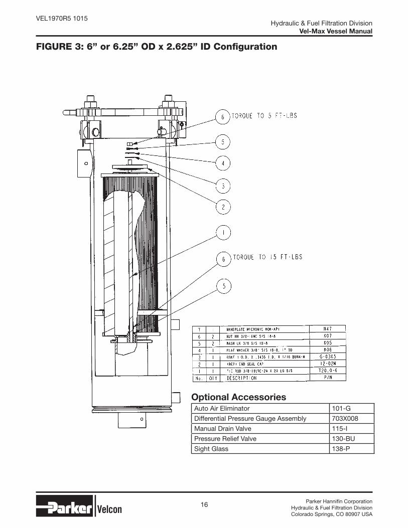
7. Install the seal plate, rubber gasket, fl at washer, lock washer, and nut as shown in Figure 3 (Page 16).
8. Torque the nut as illustrated in Figure 3 (Page 16).
NOTE USE ONLY PARKER PARKER VELCON CARTRIDGES IN THIS FILTER. PARKER HANNIFIN CANNOT WARRANT PERFORMANCE IF ANY OTHER MANUFACTURER’S CARTRIDGES ARE USED.
9 Parker Hannifi n CorporationHydraulic & Fuel Filtration DivisionColorado Springs, CO 80907 USA
Hydraulic & Fuel Filtration DivisionVel-Max Vessel Manual
VEL1970R5 1015
FUEL MONITOR USING AVIATION Aquacon® CARTRIDGES (6” OD)
DESCRIPTION
The Parker Velcon Monitor vessel configuration that you have received consists of the vessel, separately purchased monitor cartridge, and accessories to meet your specific requirements. Descriptive literature covering the accessories is included elsewhere in this manual.
The Parker Velcon Monitor vessel is specifically designed to absorb free water and remove solid contaminants from the product being filtered. The Aquacon® cartridge is mounted on the center mount. The cartridge flows outside to inside.
ADI cartridges flow inside to outside. The vessel flow direction must be reversed, with the inlet at the bottom, to use these cartridges. Make sure the flow direction is correct when using this cartridge family.
Aquacon® MONITOR CARTRIDGES
These cartridges absorb water and filter solids from avgas and jet fuel. They provide positive protection against water slug transmission. The cartridges are tested and qualified to EI 1583.
CAUTION
DO NOT USE Aquacon® MONITOR CARTRIDGES WITH PRE-MIXED FUEL CONTAINING ANTI-ICING ADDITIVES (DiEGME, FIZZY®, Prist®, or FSII)
AQUACON® MONITOR CARTRIDGE INSTALLATION
1. Make sure that you have the proper installation kit for the 6” OD Aquacon monitor cartridge.
2. Insure that the tie rod is securely mounted.
3. Remove the Aquacon cartridge from the packaging.
4. Install the cartridge by inserting over the tie rod, making sure the bottom cap is centered and squarely mounted to the base to achieve a good seal.
5. If the vessel is a VX2, install the necessary spacer seal plate to center and seal the fi lters. Install another fi lter on top of the seal plate.
6. If the vessel is a VX3, install another spacer seal plate. Install another fi lter on top of the seal plate.
7. Install the seal plate, rubber washer, fl at washer, lock washer and nut as illustrated in Figure 2 (Page 15).
8. Torque the nut as illustrated in Figure 4 (Page 17).
NOTE VESSEL MUST BE PROVIDED WITH PRESSURE RELIEF VALVE IF THE SYSTEM HAS A POSITIVE DISPLACEMENT PUMP UPSTREAM OR AUTOMATIC SHUT-OFF VALVE DOWNSTREAM OF THE VESSEL.
USE ONLY PARKER VELCON CARTRIDGES IN THIS FILTER. PARKER HANNIFIN CANNOT WARRANT PERFORMANCE IF ANY OTHER MANUFACTURER’S CARTRIDGES ARE USED.

10 Parker Hannifi n CorporationHydraulic & Fuel Filtration DivisionColorado Springs, CO 80907 USA
Hydraulic & Fuel Filtration DivisionVel-Max Vessel Manual
VEL1970R5 1015
INDUSTRIAL PREFILTER (6-1/4” OD)
DESCRIPTION
The Parker Velcon Prefilter vessel configuration that you have received consists of the vessel, separately purchased filter cartridges, and accessories to meet your specific requirements. Descriptive literature covering the accessories is included elsewhere in this manual.
The Parker Velcon Prefilter vessel is specifically designed to remove solid particles from the product being treated. The FO-7xxxx cartridges are mounted on the vessel base. The cartridges flow outside-to-inside.
FO7XXXX FILTER CARTRIDGES
Prefilter cartridges are used to remove particles from jet fuel, oils, and other petroleum products.
FO7XXXX PREFILTER CARTRIDGE INSTALLATION
1. Make sure that you have the proper installation kit for the 6-1/4” OD FO-7xxxx prefi lter.
2. Insure that the tie rod is securely mounted.
3. Remove the prefi lter cartridge from the packaging.
4. Install the fi lter over the tie rod, making sure to center and squarely mount on the base to achieve a good seal.
5. If the vessel is a VX3, install the necessary spacer seal plate.
6. Install another fi lter over the spacer seal plate.
7. Install the seal plate, rubber gasket, fl at washer, lock washer, and nut as shown in Figure 3 (Page 16).
8. Torque the nut as illustrated in Figure 3 (Page 16).
NOTE USE ONLY PARKER VELCON CARTRIDGES IN THIS FILTER. PARKER HANNIFIN CANNOT WARRANT PERFORMANCE IF ANY OTHER MANUFACTURER’S CARTRIDGES ARE USED.
AVIATION PREFILTER (6” OD)
DESCRIPTION
The Parker Velcon Prefilter vessel configuration that you have received consists of the vessel, separately purchased filter cartridges, and accessories to meet your specific requirements. Descriptive literature covering the accessories is included elsewhere in this manual.
The Parker Velcon Prefilter vessel is specifically designed to remove solid particles from the product being treated. The FO-6xxxx cartridges are mounted on the vessel base. The cartridges flow outside-to-inside.
FO6XXXX FILTER CARTRIDGES
Prefilter cartridges are used to remove particles from jet fuel, and other petroleum fuels.
FO6XXXX PREFILTER CARTRIDGE INSTALLATION
1. Make sure that you have the proper installation kit for the 6” OD aviation prefi lter.
2. Insure that the tie rod is securely mounted.
3. Remove the prefi lter cartridge from the packaging.
4. Install the fi lter over the tie rod, making sure to center and squarely mount on the base to achieve a good seal..
5. If the vessel is a VX2, install the necessary spacer seal plate on top of the fi lter. Install another fi lter on top of the seal plate.
6. If the vessel is a VX3, install another spacer seal plate and another fi lter.
7. Install the seal plate, rubber gasket, fl at washer, lock washer, and nut as shown in Figure 2 (Page 15).
8. Torque the nut as illustrated in Figure 4 (Page 17).
NOTE USE ONLY PARKER VELCON CARTRIDGES IN THIS FILTER. PARKER HANNIFIN CANNOT WARRANT PERFORMANCE IF ANY OTHER MANUFACTURER’S CARTRIDGES ARE USED.

11 Parker Hannifi n CorporationHydraulic & Fuel Filtration DivisionColorado Springs, CO 80907 USA
Hydraulic & Fuel Filtration DivisionVel-Max Vessel Manual
VEL1970R5 1015
FUEL MONITOR USING INDUSTRIAL Aquacon® CARTRIDGES (6-1/4” OD)
DESCRIPTION
The Parker Velcon Monitor vessel configuration that you have received consists of the vessel, separately purchased monitor cartridge, and accessories to meet your specific requirements. Descriptive literature covering the accessories is included elsewhere in this manual.
The Parker Velcon Monitor vessel is specifically designed to absorb free water and remove solid contaminants from the product being filtered. The Aquacon cartridge is mounted on the center mount. The cartridge flows outside to inside.
Aquacon® MONITOR CARTRIDGES
These cartridges absorb water and filter solids from lubricating and other oils. They provide positive protection against water slug transmission.
INDUSTRIAL Aquacon® MONITOR CARTRIDGE INSTALLATION
1. Make sure that you have the proper installation kit for the 6-1/4” OD industrial Aquacon cartridge.
2. Insure that the tie rod is securely mounted.
3. Remove the Aquacon AC-7xxxx cartridge from the packaging.
4. Install the cartridge by inserting over the tie rod, making sure the bottom cap is centered and squarely mounted to the base to achieve a good seal.
5. If the vessel is a VX3, install the necessary spacer seal plate to center and seal the top of the fi lter. Install another fi lter on top of the seal plate.
6. Install the seal plate, rubber washer, fl at washer, lock washer and nut as illustrated in Figure 3 (Page 16).
7. Torque the nut as illustrated in Figure 3 (Page 16).
NOTE VESSEL MUST BE PROVIDED WITH PRESSURE RELIEF VALVE IF THE SYSTEM HAS A POSITIVE DISPLACEMENT PUMP UPSTREAM OR AUTOMATIC SHUTOFF VALVE DOWNSTREAM OF THE VESSEL.
USE ONLY PARKER VELCON CARTRIDGES IN THIS FILTER. PARKER HANNIFIN CANNOT WARRANT PERFORMANCE IF ANY OTHER MANUFACTURER’S CARTRIDGES ARE USED.

12 Parker Hannifi n CorporationHydraulic & Fuel Filtration DivisionColorado Springs, CO 80907 USA
Hydraulic & Fuel Filtration DivisionVel-Max Vessel Manual
VEL1970R5 1015

13 Parker Hannifi n CorporationHydraulic & Fuel Filtration DivisionColorado Springs, CO 80907 USA
Hydraulic & Fuel Filtration DivisionVel-Max Vessel Manual
VEL1970R5 1015
Appendix

14 Parker Hannifi n CorporationHydraulic & Fuel Filtration DivisionColorado Springs, CO 80907 USA
Hydraulic & Fuel Filtration DivisionVel-Max Vessel Manual
VEL1970R5 1015
Optional Accessories Auto Air Eliminator 101-G
Differential Pressure Gauge Assembly 703X008
Manual Drain Valve 115-I
Pressure Relief Valve 130-BU
Sight Glass 138-P
FIGURE 1: FILTER/SEPARATOR CONFIGURATION
15 Parker Hannifi n CorporationHydraulic & Fuel Filtration DivisionColorado Springs, CO 80907 USA
Hydraulic & Fuel Filtration DivisionVel-Max Vessel Manual
VEL1970R5 1015
FIGURE 2: CDF MONITOR CONFIGURATION
Optional Accessories Auto Air Eliminator 101-G
Differential Pressure Gauge Assembly 703X008
Manual Drain Valve 115-I
Pressure Relief Valve 130-BU
Sight Glass 138-P
16 Parker Hannifi n CorporationHydraulic & Fuel Filtration DivisionColorado Springs, CO 80907 USA
Hydraulic & Fuel Filtration DivisionVel-Max Vessel Manual
VEL1970R5 1015
Optional Accessories Auto Air Eliminator 101-G
Differential Pressure Gauge Assembly 703X008
Manual Drain Valve 115-I
Pressure Relief Valve 130-BU
Sight Glass 138-P
FIGURE 3: 6” or 6.25” OD x 2.625” ID Confi guration

17 Parker Hannifi n CorporationHydraulic & Fuel Filtration DivisionColorado Springs, CO 80907 USA
Hydraulic & Fuel Filtration DivisionVel-Max Vessel Manual
VEL1970R5 1015
FIGURE 4: 6” OD x 3.5” ID Confi guration
Optional Accessories Auto Air Eliminator 101-G
Differential Pressure Gauge Assembly 703X008
Manual Drain Valve 115-I
Pressure Relief Valve 130-BU
Sight Glass 138-P

18 Parker Hannifi n CorporationHydraulic & Fuel Filtration DivisionColorado Springs, CO 80907 USA
Hydraulic & Fuel Filtration DivisionVel-Max Vessel Manual
VEL1970R5 1015
VEL-MAX® FILTER VESSEL
DESCRIPTION
The compact Vel-Max® Filter Vessel is suitable for flow rates up to 204 USGPM with micronic cartridges, up to 198 USGPM as a filter/separator, and up to 150 USGPM with CDF® monitor cartridges. The Vel-Max® can be used on mobile refueling equipment, fueling cabinets and for fixed fueling installations. Vel-Max® is designed for easy maintenance and easy conversion to a prefilter, filter/separator, or monitor.
APPLICATIONS
Jet Fuel
Avgas
Diesel Fuel
Biodiesel Blends
Motor Gasoline
Kerosene
Turbine Lube Oil
Insulating Oil
STANDARD FEATURES
Carbon steel construction
250 psi design pressure
Epoxy powder coated interior & exterior
2” NPT female inlet/outlet
1/2 ” NPT drain connection
3/4” NPT vent and relief connection
1/2” NPT sight glass connections
1” NPT water probe connection
1/8” NPT differential pressure gauge connections
Lid Gasket: G-2052 (Buna N)
OPTIONAL FEATURES
Air eliminator
Drain valve
Pressure relief valve
Water probe
Sight gauge
Leg assembly with adjustable height
ASME Code Stamp
CE Mark
Differential pressure gauge assembly
Lid Gasket: G-2052V (Viton)
Vel-Max® Filter Vessel, VX-2, showing
optional leg assembly, differential pressure
gauge, sight glass assembly, and air eliminator.
Max® Filter Vessss el, VX-2, shshshshooo
l l bl diff ti l
19 Parker Hannifi n CorporationHydraulic & Fuel Filtration DivisionColorado Springs, CO 80907 USA
Hydraulic & Fuel Filtration DivisionVel-Max Vessel Manual
VEL1970R5 1015
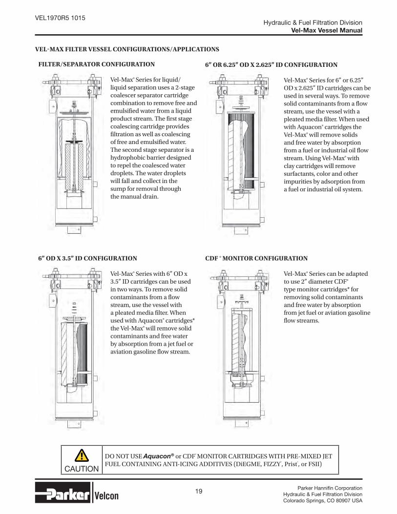
VELMAX FILTER VESSEL CONFIGURATIONS/APPLICATIONS
Vel-Max® Series can be adapted to use 2” diameter CDF® type monitor cartridges* for removing solid contaminants and free water by absorption from jet fuel or aviation gasoline flow streams.
Vel-Max® Series for 6” or 6.25” OD x 2.625” ID cartridges can be used in several ways. To remove solid contaminants from a flow stream, use the vessel with a pleated media filter. When used with Aquacon® cartridges the Vel-Max® will remove solids and free water by absorption from a fuel or industrial oil flow stream. Using Vel-Max® with clay cartridges will remove surfactants, color and other impurities by adsorption from a fuel or industrial oil system.
Vel-Max® Series with 6” OD x 3.5” ID cartridges can be used in two ways. To remove solid contaminants from a flow stream, use the vessel with a pleated media filter. When used with Aquacon® cartridges* the Vel-Max® will remove solid contaminants and free water by absorption from a jet fuel or aviation gasoline flow stream.
Vel-Max® Series for liquid/liquid separation uses a 2-stage coalescer separator cartridge combination to remove free and emulsified water from a liquid product stream. The first stage coalescing cartridge provides filtration as well as coalescing of free and emulsified water. The second stage separator is a hydrophobic barrier designed to repel the coalesced water droplets. The water droplets will fall and collect in the sump for removal through the manual drain.
CDF ® MONITOR CONFIGURATION
6” OR 6.25” OD X 2.625” ID CONFIGURATION
6” OD X 3.5” ID CONFIGURATION
FILTER/SEPARATOR CONFIGURATION
CAUTION
DO NOT USE Aquacon® or CDF® MONITOR CARTRIDGES WITH PRE-MIXED JET FUEL CONTAINING ANTI-ICING ADDITIVES (DiEGME, FIZZY®, Prist®, or FSII)
20 Parker Hannifi n CorporationHydraulic & Fuel Filtration DivisionColorado Springs, CO 80907 USA
Hydraulic & Fuel Filtration DivisionVel-Max Vessel Manual
VEL1970R5 1015
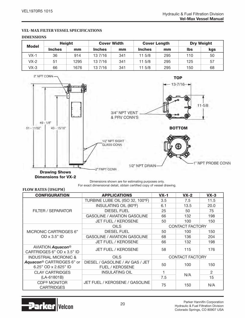
Dimensions shown are for estimating purposes only. For exact dimensional detail, obtain certified copy of vessel drawing.
TOP
Drawing Shows Dimensions for VX-2
VELMAX FILTER VESSEL SPECIFICATIONS
DIMENSIONS
ModelHeight Cover Width Cover Length Dry Weight
Inches mm Inches mm Inches mm lbs kgs
VX-1 36 914 13 7/16 341 11 5/8 295 110 50
VX-2 51 1295 13 7/16 341 11 5/8 295 125 57
VX-3 66 1676 13 7/16 341 11 5/8 295 150 68
FLOW RATES USGPM CONFIGURATION APPLICATIONS VX-1 VX-2 VX-3
FILTER / SEPARATOR
TURBINE LUBE OIL (ISO 32, 100ºF) 3.5 7.5 11.5INSULATING OIL (80ºF) 6.1 13.5 20.0
DIESEL FUEL 25 50 75GASOLINE / AVIATION GASOLINE 66 132 198
JET FUEL / KEROSENE 50 100 150
MICRONIC CARTRIDGES 6” OD x 3.5” ID
OILS CONTACT FACTORYDIESEL FUEL 50 100 150
GASOLINE / AVIATION GASOLINE 68 136 204JET FUEL / KEROSENE 66 132 198
AVIATION Aquacon® CARTRIDGES 6” OD x 3.5” ID
JET FUEL / KEROSENE 58 115 176
INDUSTRIAL MICRONIC & Aquacon® CARTRIDGES 6” or
6.25” OD x 2.625” ID
OILS CONTACT FACTORYDIESEL / GASOLINE / AV GAS / JET
FUEL / KEROSENE50 100 150
CLAY CARTRIDGES (LA-61801B)
INSULATING OIL 1N/A
2
JET FUEL / KEROSENE / GASOLINE7.5 15
CDF® MONITOR CARTRIDGES
75 150 N/A
BOTTOM

21 Parker Hannifi n CorporationHydraulic & Fuel Filtration DivisionColorado Springs, CO 80907 USA
Hydraulic & Fuel Filtration DivisionVel-Max Vessel Manual
VEL1970R5 1015
VELMAX CARTRIDGE SELECTION TABLE CARTRIDGES
FILTER/SEPARATOR CONFIGURATIONFIRST STAGE COALESCERS FOR: MICRON RATING VX-1 VX-2 VX-3
DIESEL FUEL25 O-8150 O-8300 O-84403 O-8154 O-8304 O-8444
DIESEL FUEL / GASOLINE 2 O-8156 O-8306 O-8446JET FUEL / KEROSENE / DIESEL FUEL / TURBINE LUBE OIL / INSULATING OIL
0.5 O-81588 O-83088 O-84488
SECOND STAGE SEPARATORS FOR: TYPE VX-1 VX-2 VX-3
DIESEL PAPER SO-415PL SO-430PL SO-444PLJET / KERO / GAS / OILS TCS SO-415VX5 SO-430VX5 SO-444C
6” OD X 3.5” ID CONFIGURATION TYPE VX-1 VX-2 VX-3
MICRONIC CARTRIDGES
PLEATED PAPER FO-614PLFxxFO-614PLFxx (STACK OF 2)
FO-614PLFxx (STACK OF 3)
FO-629PLFxx FO-644PLFxx
FIBERGLASS DEPTH FO-614FGxxFO-614FGxx (STACK OF 2)
FO-614FGxx (STACK OF 3)
FO-629FGxx FO-644FGxx
AVIATION Aquacon® CARTRIDGES* ACO-61401LACO-61401L (STACK OF 2)
ACO-61405 (STACK OF 3)
ACO-62901L ACO-64401L
INDUSTRIAL Aquacon® CARTRIDGESAC-61405 A(C/D)-614xx
(STACK OF 2)A(C/D)-614xx (STACK OF 3)AD-61410
AD-61425 AC-62905 AC-64405
6” OR 6.25” OD X 2.5625” ID CONFIGURATION VX-1 VX-2 VX-3
MICRONIC CARTRIDGES
PLEATED PAPER (FO) & PLEATED SYNTHETIC
(FOS)
FO-718PLxx
N/A
(FO/FOS)-718xx (STACK OF 2)FOS-618PLxx
FOS-718PLxx FO-736PLxxFOS-636PLxx
FIBERGLASS DEPTH FO-618FGAxxFO-618FGAxx (STACK OF 2)
FO-636FGAxx
INDUSTRIAL Aquacon® CARTRIDGES AC-718xxAC-718xx
(STACK OF 2)
AC-736xxCLAY (FULLER’S EARTH) CARTRIDGES LA-61801B
LA-61801B (STACK OF 2)
CDF® MONITOR CONFIGURATION VX-1 VX-2 VX-3
CDF® CARTRIDGES* CDF-215N CDF-230N N/A
The suffix “xx” on the part number of cartridges denotes the micron rating of the cartridge. Contact the Hydraulic & Fuel Filtration Division for available micron ratings.
HARDWARE KITS
CONFIGURATION VX-1 VX-2 VX-3
FILTER / SEPARATOR (COALESCER + SEPARATOR) VX1-FSKIT VX2-FSKIT VX3-FSKIT
6” OD X 3.5” ID CARTRIDGE(S) VX1-AVKIT VX2-AVKIT VX3-AVKIT
6” OR 6.25” OD X 2.5625” ID CARTRIDGE(S) VX1-INKIT N/A VX3-INKIT
CDF® MONITOR CARTRIDGES VX1-CDKIT VX2-CDKIT N/A
*CAUTION: Do not use Aquacon® or CDF® water absorbing monitor cartridges in pre-mixed jet fuel containing anti-icing additives(DiEGME, FIZZY®, Prist®, FSII)
22 Parker Hannifi n CorporationHydraulic & Fuel Filtration DivisionColorado Springs, CO 80907 USA
Hydraulic & Fuel Filtration DivisionVel-Max Vessel Manual
VEL1970R5 1015
SEPARATOR CARTRIDGES
FEATURES
Optimum 2nd stage water removal
Choice of Teflon® Coated Screen, Synthetic or Pleated Paper Media
Field proven performance
Largest selection of replacement elements
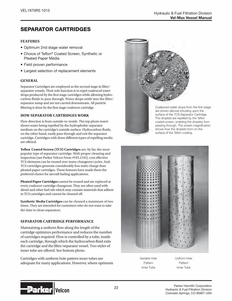
GENERAL
Separator Cartridges are employed as the second stage in filter/ separator vessels. Their sole function is to repel coalesced water drops produced by the first stage cartridges while allowing hydro-carbon fluids to pass through. Water drops settle into the filter/ separator sump and are not carried downstream. All particle filtering is done by the first stage coalescer cartridge.
HOW SEPARATOR CARTRIDGES WORK
Flow direction is from outside-to-inside. The top photo insert shows water being repelled by the hydrophobic separator medium on the cartridge’s outside surface. Hydrocarbon fluids, on the other hand, easily pass through and exit the separator cartridge. Cartridges with three different types of repelling media are offered:
Teflon® Coated Screen (TCS) Cartridges are, by far, the most popular type of separator cartridge. With proper cleaning and inspection (see Parker Velcon Form #VEL1242), cost effective TCS elements can be reused over many changeout cycles. And, TCS cartridges generate considerably less static charge than pleated paper cartridges. These features have made them the preferred choice for aircraft fueling applications.
Pleated Paper Cartridges cannot be reused and are replaced at every coalescer cartridge changeout. They are often used with diesel and other fuel oils which may contain materials that adhere to TCS cartridges and cannot be cleaned off.
Synthetic Media Cartridges can be cleaned a maximum of two times. They are intended for customers who do not want to take the time to clean separators.
SEPARATOR CARTRIDGE PERFORMANCE
Maintaining a uniform flow along the length of the cartridge optimizes performance and reduces the number of cartridges required. Flow is controlled by a tube, inside each cartridge, through which the hydrocarbon fluid exits the cartridge and the filter/separator vessel. Two styles of inner tube are offered. See bottom photo.
Cartridges with uniform hole pattern inner tubes are adequate for many applications. However, where optimum
Coalesced water drops from the first stage
are shown (above) intruding upon the
surface of the TCS Separator Cartridge.
The droplets are repelled by the Teflon
coated screen, enabling the droplets from
passing through. The screen magnification
shows how the droplets form on the
surface of the Teflon coating.
Uniform Hole
Pattern
Inner Tube
Variable Hole
Pattern
Inner Tube

23 Parker Hannifi n CorporationHydraulic & Fuel Filtration DivisionColorado Springs, CO 80907 USA
Hydraulic & Fuel Filtration DivisionVel-Max Vessel Manual
VEL1970R5 1015
flow distribution is required, cartridges with variable hole pattern inner tubes are recommended. When converting older equipment, a lesser number of variable hole pattern cartridges is usually required. Operating costs will therefore be reduced.
SEPARATOR CARTRIDGES
Model numbers containing a “C” in denotes a uniform hole pattern on the inner tube with TCS media, while the codes with a “V” signifies a variable hole pattern with TCS media. Blind caps have a hole for the tie rod.
Parker Velcon Model Numbers include significant
product information.
Example:SO - 6 36 PV
CARTRIDGE CODE IDENTIFICATION
ModelFlow Control(hole pattern)
OD(in.)
Mounting End ID
(in.)
Opposite End ID
(in.) MediaSO-3xxC Uniform 31∕16 2 Blind TCS
SO-3xxV Variable 31∕16 2 Blind TCS
SO-4xxC Uniform 49∕16 3½ Blind TCS
SO-4xxV Variable 49∕16 3½ Blind TCS
SO-6xxC Uniform 6 3½ 3½ TCS
SO-6xxCA Uniform 6 3½ Blind TCS
SO-6xxCM Uniform 6 4½ Blind TCS
SO-6xxVA(5) Variable 6 3½ Blind TCS
SO-6xxV(5) Variable 6 4½ Blind TCS
SO-6xxPV(5) Variable 6 41/8 Blind TCS
SO-6xxPLF3* Uniform 6 3½ 3½PleatedPaper
SO-6xxPLBZ* Uniform 6 3½ BlindPleatedPaper
SO-6xxVASN(5)** Variable 6 3½ Blind Synthetic
SO-6xxVSN(5)** Variable 6 4½ Blind Synthetic
SO-6xxPVSN(5)** Variable 6 41/8 Blind Synthetic
*The shelf life for pleated paper separators (for example, SO-xxxPLF3 and SO-6xxPLBZ) is one year.**Dave Hawkins to Provide Patent #s.
GENERAL SPECIFICATIONS
TCS medium is 200 mesh stainless steel screen coated on both sides with green Teflon®
The screen is lockseam folded and fastened with an internal aluminum clip
Pleated medium is silicone treated resin impregnated paper with a protective outer aluminum screen jacket
Tubes are aluminum
End caps are aluminum and/or glass filled nylon
Gaskets are Buna-N
pH range is 5 to 9
Maximum operating temperature is 200°F
SO SERIES CARTRIDGES
The code identification table to the left are the most commonly used. A variety of other styles are available for special applications. Contact a local area distributor for details.
SO-6xxPLF3 pleated separators come in lengths of 11,14, 16, 29, and 33 inches. SO-6xxPLBZ pleated separators come in lengths of 22, 29, 33, and 44 inches.
SO-6xxC cartridges are available in these same stackable lengths plus longer lengths. Single-unit designs, however, are recommended for installation ease and lower cost. Other styles listed in the table are not intended to be stacked.
Parker Velcon variable size hole pattern cart ridges should not be replaced with uniform hole pattern cartridges unless appropriate full-scale test data can be supplied showing equivalent performance.
For more information about EI 1581 5th Edition qualified separators, please reference data sheet 1923.
SO-6xxVASN/VSN/PVSN separators are intended for customers who want a separator for disposal use rather than a re-useable filter, which can be cleaned a maximum of two times.
Code Identifying Media, Tube Type, and End Cap DesignApprox. Length in inchesApprox. Diameter in inchesOutside-to-Inside Flow Separator Cartridge
24 Parker Hannifi n CorporationHydraulic & Fuel Filtration DivisionColorado Springs, CO 80907 USA
Hydraulic & Fuel Filtration DivisionVel-Max Vessel Manual
VEL1970R5 1015
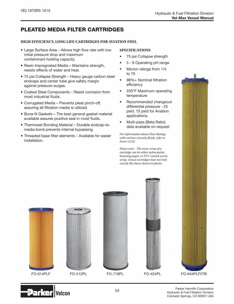
FO-424PLFO-718PLFO-512PL FO-644PLF5TBFO-614PLF
Large Surface Area – Allows high flow rate with low initial pressure drop and maximum contaminant holding capacity.
Resin Impregnated Media – Maintains strength, resists effects of water and heat.
75 psi Collapse Strength – Heavy gauge carbon steel endcaps and center tube give safety margin against pressure surges.
Coated Steel Components – Resist corrosion from most industrial fluids.
Corrugated Media – Prevents pleat pinch-off, assuring all filtration media is utilized.
Buna-N Gaskets – The best general gasket material available assures positive seal in most fluids.
Thermoset Bonding Material – Durable endcap-to-media bond prevents internal bypassing.
Threaded base filter elements – Available for easier installation.
SPECIFICATIONS
• 75 psi Collapse strength
• 5 - 9 Operating pH range
• Micron ratings from 1/4 to 75
• 98%+ Nominal filtration efficiency
• 250°F Maximum operating temperature
• Recommended changeout differential pressure - 25 psid. 15 psid for Aviation applications.
• Multi-pass (Beta Ratio) data available on request
For information about Flow Ratings with various viscosity fluids, refer to Form #1532
Please note – The outer wrap of a cartridge can be either nylon jacket, beaming paper, or PVC-coated screen wrap. Actual cartridges may not look exactly like those shown in photo.
PLEATED MEDIA FILTER CARTRIDGES
HIGH EFFICIENCY, LONG LIFE CARTRIDGES FOR AVIATION FUEL
25 Parker Hannifi n CorporationHydraulic & Fuel Filtration DivisionColorado Springs, CO 80907 USA
Hydraulic & Fuel Filtration DivisionVel-Max Vessel Manual
VEL1970R5 1015
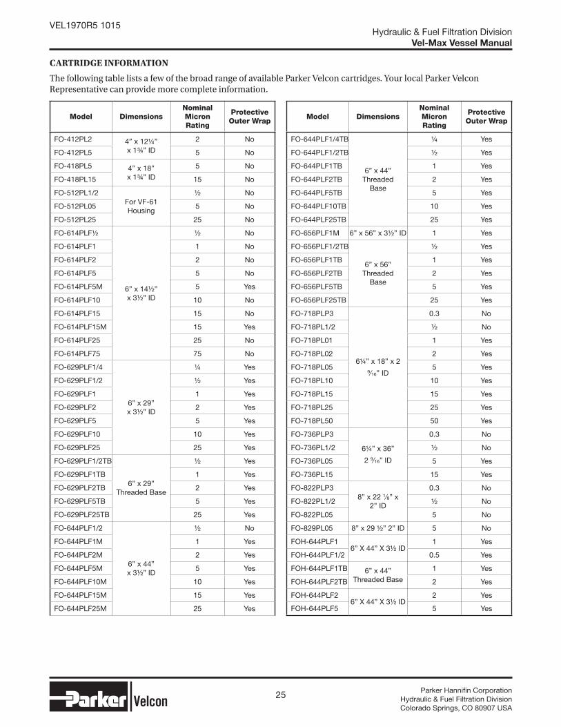
CARTRIDGE INFORMATION
The following table lists a few of the broad range of available Parker Velcon cartridges. Your local Parker Velcon Representative can provide more complete information.
Model DimensionsNominal Micron Rating
Protective Outer Wrap
FO-412PL2 4” x 12¼”x 1¾” ID
2 No
FO-412PL5 5 No
FO-418PL5 4” x 18”x 1¾” ID
5 No
FO-418PL15 15 No
FO-512PL1/2For VF-61 Housing
½ No
FO-512PL05 5 No
FO-512PL25 25 No
FO-614PLF½
6” x 14½”x 3½” ID
½ No
FO-614PLF1 1 No
FO-614PLF2 2 No
FO-614PLF5 5 No
FO-614PLF5M 5 Yes
FO-614PLF10 10 No
FO-614PLF15 15 No
FO-614PLF15M 15 Yes
FO-614PLF25 25 No
FO-614PLF75 75 No
FO-629PLF1/4
6” x 29”x 3½” ID
¼ Yes
FO-629PLF1/2 ½ Yes
FO-629PLF1 1 Yes
FO-629PLF2 2 Yes
FO-629PLF5 5 Yes
FO-629PLF10 10 Yes
FO-629PLF25 25 Yes
FO-629PLF1/2TB
6” x 29”Threaded Base
½ Yes
FO-629PLF1TB 1 Yes
FO-629PLF2TB 2 Yes
FO-629PLF5TB 5 Yes
FO-629PLF25TB 25 Yes
FO-644PLF1/2
6” x 44”x 3½” ID
½ No
FO-644PLF1M 1 Yes
FO-644PLF2M 2 Yes
FO-644PLF5M 5 Yes
FO-644PLF10M 10 Yes
FO-644PLF15M 15 Yes
FO-644PLF25M 25 Yes
Model DimensionsNominal Micron Rating
Protective Outer Wrap
FO-644PLF1/4TB
6” x 44”Threaded
Base
¼ Yes
FO-644PLF1/2TB ½ Yes
FO-644PLF1TB 1 Yes
FO-644PLF2TB 2 Yes
FO-644PLF5TB 5 Yes
FO-644PLF10TB 10 Yes
FO-644PLF25TB 25 Yes
FO-656PLF1M 6” x 56” x 3½” ID 1 Yes
FO-656PLF1/2TB
6” x 56”Threaded
Base
½ Yes
FO-656PLF1TB 1 Yes
FO-656PLF2TB 2 Yes
FO-656PLF5TB 5 Yes
FO-656PLF25TB 25 Yes
FO-718PLP3
6¼” x 18” x 2 9∕16” ID
0.3 No
FO-718PL1/2 ½ No
FO-718PL01 1 Yes
FO-718PL02 2 Yes
FO-718PL05 5 Yes
FO-718PL10 10 Yes
FO-718PL15 15 Yes
FO-718PL25 25 Yes
FO-718PL50 50 Yes
FO-736PLP3
6¼” x 36”
2 9∕16” ID
0.3 No
FO-736PL1/2 ½ No
FO-736PL05 5 Yes
FO-736PL15 15 Yes
FO-822PLP38” x 22 1∕8” x
2” ID
0.3 No
FO-822PL1/2 ½ No
FO-822PL05 5 No
FO-829PL05 8” x 29 ½” 2” ID 5 No
FOH-644PLF16” X 44” X 3½ ID
1 Yes
FOH-644PLF1/2 0.5 Yes
FOH-644PLF1TB 6” x 44” Threaded Base
1 Yes
FOH-644PLF2TB 2 Yes
FOH-644PLF26” X 44” X 3½ ID
2 Yes
FOH-644PLF5 5 Yes

26 Parker Hannifi n CorporationHydraulic & Fuel Filtration DivisionColorado Springs, CO 80907 USA
Hydraulic & Fuel Filtration DivisionVel-Max Vessel Manual
VEL1970R5 1015
Aquacon® WATER ABSORBING CARTRIDGES
REMOVE WATER AND DIRT FROM OILS, FUELS AND GASES
Removes free and emulsified water to less than 2 ppm
Differential pressure increase alerts operator to change cartridges
Effectively filters silt and other particulates
No media migration or “linting”
Easy to install and remove
Does not affect oil additives
Fits standard filter housings
Aquacon® Cartridges have a patented* construction for removing dirt and water from hydrocarbon and other oils as well as gases. The outer media layer filters out silt, rust and other particulate contaminants. The inner layers absorb water and chemically bond it so that no water will release downstream.
When the Aquacon Cartridge reaches its water holding limit, the media swells shut and the differential pressure rapidly increases. This signals the operator that the cartridge must be changed.
APPLICATIONS
Gasoline Hydraulic Oil
Kerosene Turbine Lube Oil
Diesel Fuel Quench Oil
Insulating Oil Synthetic Oil
Biodiesel Phosphate Ester Oil
TECHNICAL INFORMATION
1. Maximum operating temperature is 250°F.
2. Aquacon Cartridges will shut off fl ow when loaded with water or dirt. Appropriate precautions should be taken in critical applications where oil fl ow must be maintained.
3. With some lube and hydraulic oils all of the water may not be removed in one pass, and extra passes will be required for total removal.
4. Water capacity for the AC-718 cartridges ranges from 2 to 4 quarts.
WARNING: Absorbent-type monitor cartridges will not remove water from fuel containing alcohol blending agents (commonly called gasohol). For removal of solids, please use Parker Velcon particle removal filters specifically made for gasohol. Consult your Parker Velcon representative.

27 Parker Hannifi n CorporationHydraulic & Fuel Filtration DivisionColorado Springs, CO 80907 USA
Hydraulic & Fuel Filtration DivisionVel-Max Vessel Manual
VEL1970R5 1015
Buna-N Gaskets
Thermoset Adhesive Bonding Endcaps
to Media
Inner Absorbing Layers and Media Migration Barrier
Coated Steel Centertubes and Endcaps
Pleated Layers of Filtering, Absorbing and Support Media
CARTRIDGE INFORMATION
New types of Aquacon® Cartridges are being introduced continually.
Contact your local Parker Velcon Representative for up-to-date information.
Model Number
Micrometer ReadingI.D.
InchesO.D.
InchesLengthInches
Collapse Pressure, psi
InterchangeInformationNormal
Betax = 75
AC-21005(1) 5 40 1 2 5/8 9 3/4 75Fits Parker Velcon VF-31 Housings
AC-5121/2E(2) 0.5 3 1 7/8 5 5/8 12 1/8 75 Fits Parker Velcon VF-61 HousingsAC-51205 5 40 1 7/8 5 5/8 12 1/8 75
AC-52405 5 40 1 7/8 5 5/8 24 1/2 75Fits Parker Velcon VF-62 Housings
AC-61405 5 40 3 1/2 6 14 1/2 100 Interchanges with Parker Velcon FO-614PLF, FO-629PLF, and FO-644PLF Series Cartridges
AC-62905 5 40 3 1/2 6 29 1/2 100
AC-64405 5 40 3 1/2 6 44 100
AC-718P3(2) 0.3 2 2 9/16 61/4 18 75 Fits Parker Velcon industrial housings and portable filters, interchangeable with Parker Velcon FO-718PL and FO-736PL Series Cartridges
AC-718P4D 0.4 2.5 2 9/16 6 1/4 18 75
AC-7181/2(2) 0.5 3 2 9/16 6 1/4 18 75
AC-71801 1 6 2 9/16 6 1/4 18 75
AC-71805 5 40 2 9/16 6 1/4 18 75
AC-7361/2(2) 0.5 3 2 9/16 6 1/4 36 75
AC-73601 1 6 2 9/16 6 1/4 36 75
AC-73605 5 40 2 9/16 6 1/4 36 75
Notes: (1) The AC-21005 will fit into many existing housings that take “string-wound” cartridges.Check to confirm that the 9 3/4” length will seat properly in the housing.
Notes: (2) The AC-5121/2E, AC-718P3, AC-7181/2 and AC-7361/2 are increased surface area/reduced water capacity cartridges specifically designed for circuit breaker oil.
TYPICAL AQUACON CARTRIDGE CONSTRUCTION
28 Parker Hannifi n CorporationHydraulic & Fuel Filtration DivisionColorado Springs, CO 80907 USA
Hydraulic & Fuel Filtration DivisionVel-Max Vessel Manual
VEL1970R5 1015
ACO AQUACON® AVIATION FUEL FILTER CARTRIDGES
Free and emulsified water removalto less than 5 ppm
1/2 micrometer particle removal
Provides protection against “slugs” of water
Pressure increase signals need for cartridge change
Use with existing filter housings
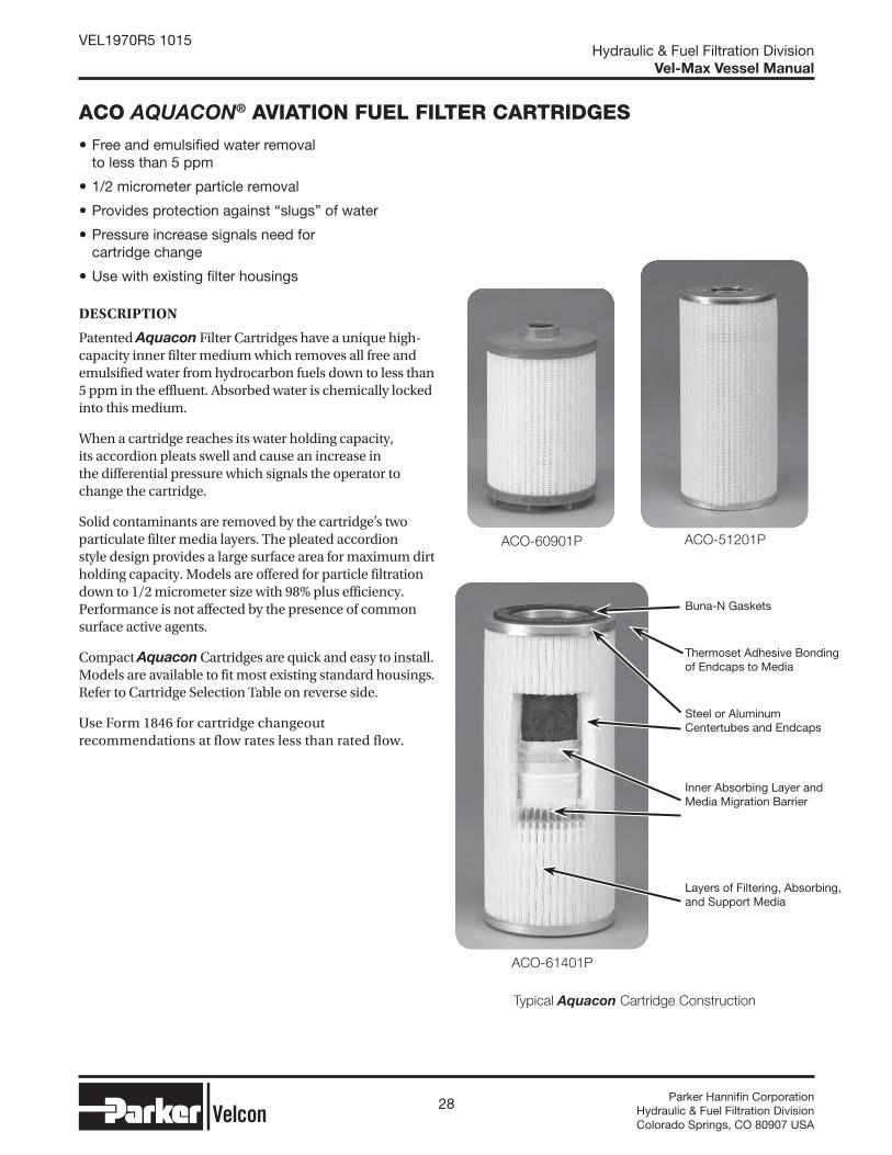
DESCRIPTION
Patented Aquacon Filter Cartridges have a unique high-capacity inner filter medium which removes all free and emulsified water from hydrocarbon fuels down to less than 5 ppm in the effluent. Absorbed water is chemically locked into this medium.
When a cartridge reaches its water holding capacity, its accordion pleats swell and cause an increase in the differential pressure which signals the operator to change the cartridge.
Solid contaminants are removed by the cartridge’s two particulate filter media layers. The pleated accordion style design provides a large surface area for maximum dirt holding capacity. Models are offered for particle filtration down to 1/2 micrometer size with 98% plus efficiency. Performance is not affected by the presence of common surface active agents.
Compact Aquacon Cartridges are quick and easy to install. Models are available to fit most existing standard housings. Refer to Cartridge Selection Table on reverse side.
Use Form 1846 for cartridge changeout recommendations at flow rates less than rated flow.
ACO-60901P ACO-51201P
Typical Aquacon Cartridge Construction
Buna-N Gaskets
Thermoset Adhesive Bonding of Endcaps to Media
Steel or AluminumCentertubes and Endcaps
Inner Absorbing Layer and Media Migration Barrier
Layers of Filtering, Absorbing, and Support Media
ACO-61401P
29 Parker Hannifi n CorporationHydraulic & Fuel Filtration DivisionColorado Springs, CO 80907 USA
Hydraulic & Fuel Filtration DivisionVel-Max Vessel Manual
VEL1970R5 1015
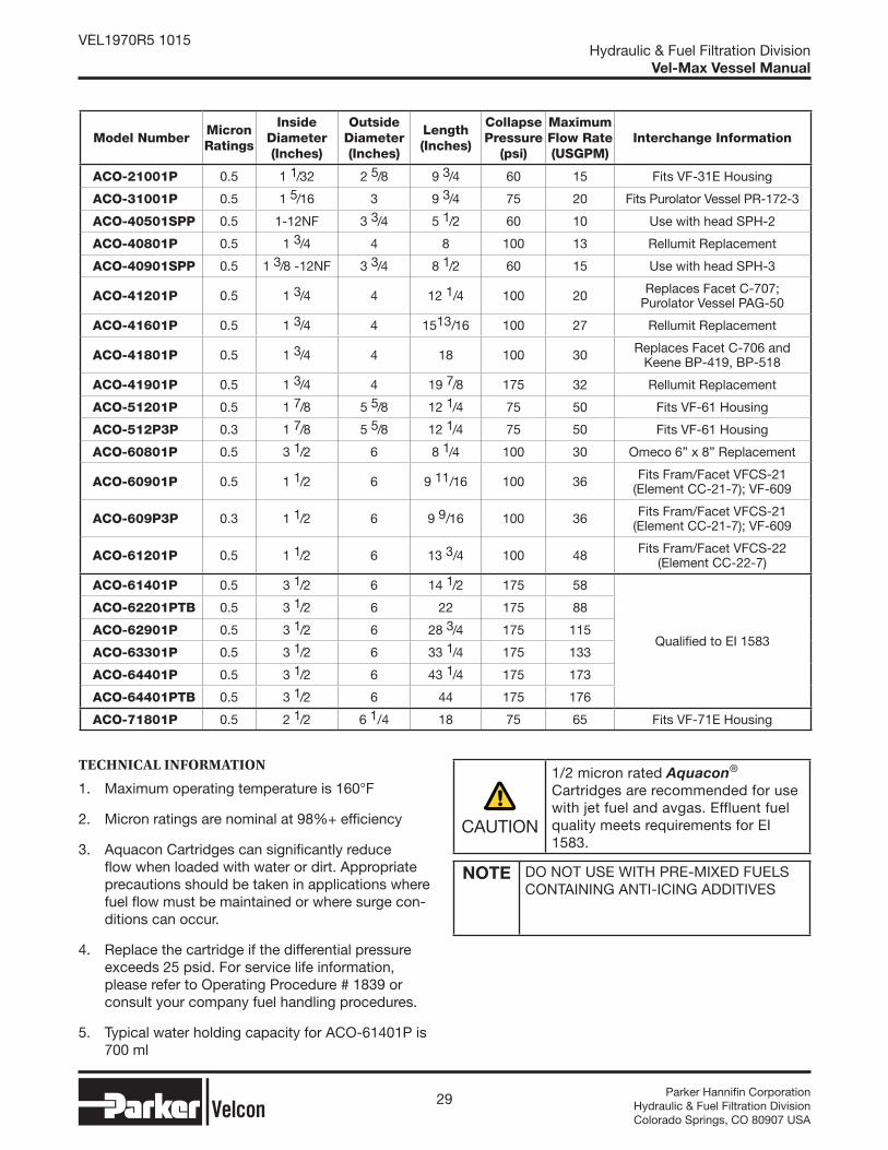
TECHNICAL INFORMATION
1. Maximum operating temperature is 160°F
2. Micron ratings are nominal at 98%+ effi ciency
3. Aquacon Cartridges can signifi cantly reduce fl ow when loaded with water or dirt. Appropriate precautions should be taken in applications where fuel fl ow must be maintained or where surge con-ditions can occur.
4. Replace the cartridge if the differential pressure exceeds 25 psid. For service life information, please refer to Operating Procedure # 1839 or consult your company fuel handling procedures.
5. Typical water holding capacity for ACO-61401P is 700 ml
CAUTION
1/2 micron rated Aquacon® Cartridges are recommended for use with jet fuel and avgas. Effluent fuel quality meets requirements for EI 1583.
NOTE DO NOT USE WITH PRE-MIXED FUELS CONTAINING ANTI-ICING ADDITIVES
Model NumberMicron Ratings
Inside Diameter (Inches)
Outside Diameter (Inches)
Length (Inches)
Collapse Pressure
(psi)
Maximum Flow Rate (USGPM)
Interchange Information
ACO-21001P 0.5 1 1/32 2 5/8 9 3/4 60 15 Fits VF-31E Housing
ACO-31001P 0.5 1 5/16 3 9 3/4 75 20 Fits Purolator Vessel PR-172-3
ACO-40501SPP 0.5 1-12NF 3 3/4 5 1/2 60 10 Use with head SPH-2
ACO-40801P 0.5 1 3/4 4 8 100 13 Rellumit Replacement
ACO-40901SPP 0.5 1 3/8 -12NF 3 3/4 8 1/2 60 15 Use with head SPH-3
ACO-41201P 0.5 1 3/4 4 12 1/4 100 20 Replaces Facet C-707;Purolator Vessel PAG-50
ACO-41601P 0.5 1 3/4 4 1513/16 100 27 Rellumit Replacement
ACO-41801P 0.5 1 3/4 4 18 100 30 Replaces Facet C-706 andKeene BP-419, BP-518
ACO-41901P 0.5 1 3/4 4 19 7/8 175 32 Rellumit Replacement
ACO-51201P 0.5 1 7/8 5 5/8 12 1/4 75 50 Fits VF-61 Housing
ACO-512P3P 0.3 1 7/8 5 5/8 12 1/4 75 50 Fits VF-61 Housing
ACO-60801P 0.5 3 1/2 6 8 1/4 100 30 Omeco 6” x 8” Replacement
ACO-60901P 0.5 1 1/2 6 9 11/16 100 36 Fits Fram/Facet VFCS-21(Element CC-21-7); VF-609
ACO-609P3P 0.3 1 1/2 6 9 9/16 100 36 Fits Fram/Facet VFCS-21(Element CC-21-7); VF-609
ACO-61201P 0.5 1 1/2 6 13 3/4 100 48 Fits Fram/Facet VFCS-22(Element CC-22-7)
ACO-61401P 0.5 3 1/2 6 14 1/2 175 58
Qualified to EI 1583
ACO-62201PTB 0.5 3 1/2 6 22 175 88
ACO-62901P 0.5 3 1/2 6 28 3/4 175 115
ACO-63301P 0.5 3 1/2 6 33 1/4 175 133
ACO-64401P 0.5 3 1/2 6 43 1/4 175 173
ACO-64401PTB 0.5 3 1/2 6 44 175 176
ACO-71801P 0.5 2 1/2 6 1/4 18 75 65 Fits VF-71E Housing
30 Parker Hannifi n CorporationHydraulic & Fuel Filtration DivisionColorado Springs, CO 80907 USA
Hydraulic & Fuel Filtration DivisionVel-Max Vessel Manual
VEL1970R5 1015
CDF® FUEL MONITOR CARTRIDGES - EI 1583 6TH EDITION P SERIES
FIELD PROVEN: CDF® REPLACEMENT CARTRIDGES ASSURE CLEAN DRY FUEL DELIVERY
FEATURES
CDF® P SERIES are qualified to EI 1583 Sixth Edition specification for Aviation Fuel Filter Monitors.
IMPROVED SALT WATER PERFORMANCE
CONDUCTIVE END CAPS and adhesive to reduce static charge within the vessel.
O-RING SEAL minimizes the possibility of bypassing contaminated fuel at differential pressures up to 175 psi.
RUGGED CONSTRUCTION collapse strength exceeds 175 psi differential pressure.
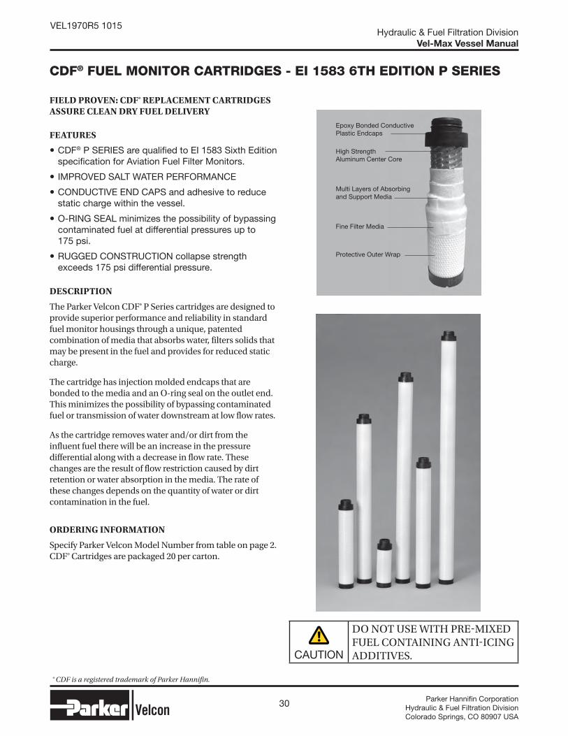
DESCRIPTION
The Parker Velcon CDF® P Series cartridges are designed to provide superior performance and reliability in standard fuel monitor housings through a unique, patented combination of media that absorbs water, filters solids that may be present in the fuel and provides for reduced static charge.
The cartridge has injection molded endcaps that are bonded to the media and an O-ring seal on the outlet end. This minimizes the possibility of bypassing contaminated fuel or transmission of water downstream at low flow rates.
As the cartridge removes water and/or dirt from the influent fuel there will be an increase in the pressure differential along with a decrease in flow rate. These changes are the result of flow restriction caused by dirt retention or water absorption in the media. The rate of these changes depends on the quantity of water or dirt contamination in the fuel.
ORDERING INFORMATION
Specify Parker Velcon Model Number from table on page 2. CDF® Cartridges are packaged 20 per carton.
CAUTION
DO NOT USE WITH PREMIXED FUEL CONTAINING ANTIICING ADDITIVES.
Epoxy Bonded Conductive Plastic Endcaps
High Strength Aluminum Center Core
Multi Layers of Absorbing and Support Media
Fine Filter Media
Protective Outer Wrap
® CDF is a registered trademark of Parker Hannifin.

31 Parker Hannifi n CorporationHydraulic & Fuel Filtration DivisionColorado Springs, CO 80907 USA
Hydraulic & Fuel Filtration DivisionVel-Max Vessel Manual
VEL1970R5 1015
EI SPECIFICATION 1583 SIXTH EDITION INFORMATION
Parker Velcon CDF®-P Series Cartridges incorporate several structural features due to requirements of the Sixth Edition of EI 1583. Some of these include:
• Increased product conductivity to decrease the risk of electrostatic discharges
• Improved media structure to lower the risk of media migration
• Lower initial DP - a major factor for installations that require changing cartridges at 15 PSID.
• New structure that provides longer cartridge life in the presence of small amounts of water
Some of the new requirements of the sixth edition of EI 1583 are:
• 18 lab qualification tests vs. 14 for the 4th edition• Testing salt resistance• Testing for cartridge conductivity• Testing for structural integrity• Testing for any trace SAP migration• Water slug test at low flow (10% of rated flow)• Low water (50 ppmv) at low flow (10% of rated
flow)
CARTRIDGE SELECTION TABLE
CartridgeFlow RateUSGPM
Parker VelconModel
Number
OverallLength
Replacements for:FacetModel
Number
RacorModel
Number
FaudiModel
Number
5 CDF-205P 513/16”FG-205 (-3, -4 or -6)
GNG-205RMO-205-4-E
—M.2-134
(/4, /E or /6B)
10 CDF-210P 1013/16”FG-210 (-3, -4 or -6)
GNG-210
FMI-10203FM-10202
RMO-210-4-E
M.2-261(/4, /E or /6B)
15 CDF-215P 1513/16”FG-215 (-3, -4 or -6)
GNG-215
FMI-15203FM-15202
RMO-215-4-E
M.2-387(/4, /E or /6B)
20 CDF-220P 2013/16”FG-220 (-3, -4 or -6)
GNG-220
FMI-20203FM-20202
RMO-220-4-E
M.2-515(/4, /E or /6B)
25 CDF-225P 2513/16”FG-225 (-3, -4 or -6)
GNG-225
FMI-25203FM-25202
RMO-225-4-E
M.2-642(/4, /E or /6B)
30 CDF-230P 3013/16” FG-230 (-3, -4 or -6)
GNG-230
FMI-30203FM-30202
RMO-230-4-E
M.2-770(/4, /E or /6B)
SPECIFICATIONS AND TECHNICAL INFORMATION CDF® P SERIES
• 175 psid (12 bar) collapse strength• 0.5 micron rating• 160°F maximum operating temperature• Recommended changeout differential pressure
= 25 psid• Typical water holding capacity for CDF-230P
is 120 ml.• For service life information, please refer to
Operating Procedures # 1839 or consult your company fuel handling procedures.
32 Parker Hannifi n CorporationHydraulic & Fuel Filtration DivisionColorado Springs, CO 80907 USA
Hydraulic & Fuel Filtration DivisionVel-Max Vessel Manual
VEL1970R5 1015
SYNTHETIC MEDIA FILTER CARTRIDGES - FOS SERIES
HIGH PERFORMANCE REPLACEMENTS FOR PLEATED PAPER CARTRIDGES UPGRADE YOUR OIL FILTRATION USING EXISTING HOUSINGS
FEATURES
Superior Filtration Efficiency
Long-Life Durability
Low Pressure Drop
High Flow Rates
No New Hardware Required
DESCRIPTIONS
FOS Series synthetic media cartridges provide excellent filtration performance for a wide variety of industrial applications. They excel in applications where water or chemicals cause softening or degradation of conventional resin impregnated cellulose (pleated paper) filter media.
Due to the finer synthetic fibers used, FOS cartridges have a low pressure drop. Replacing an equivalent size paper filter will, in many cases, result in improved filtration efficiency, higher flow rates, longer service life, and significant cost savings.
APPLICATIONS
All Hydrocarbon Fuels
Cutting Oils
Insulating Oils
Glycols
Toluol
Naphtha
Diesel Fuel
Lube Oils
Hydraulic Oils
Water Emulsion Coolants
Biodiesel Fuel
Synthetic Oils
Ethyl Alcohol
Degreasing Fluids
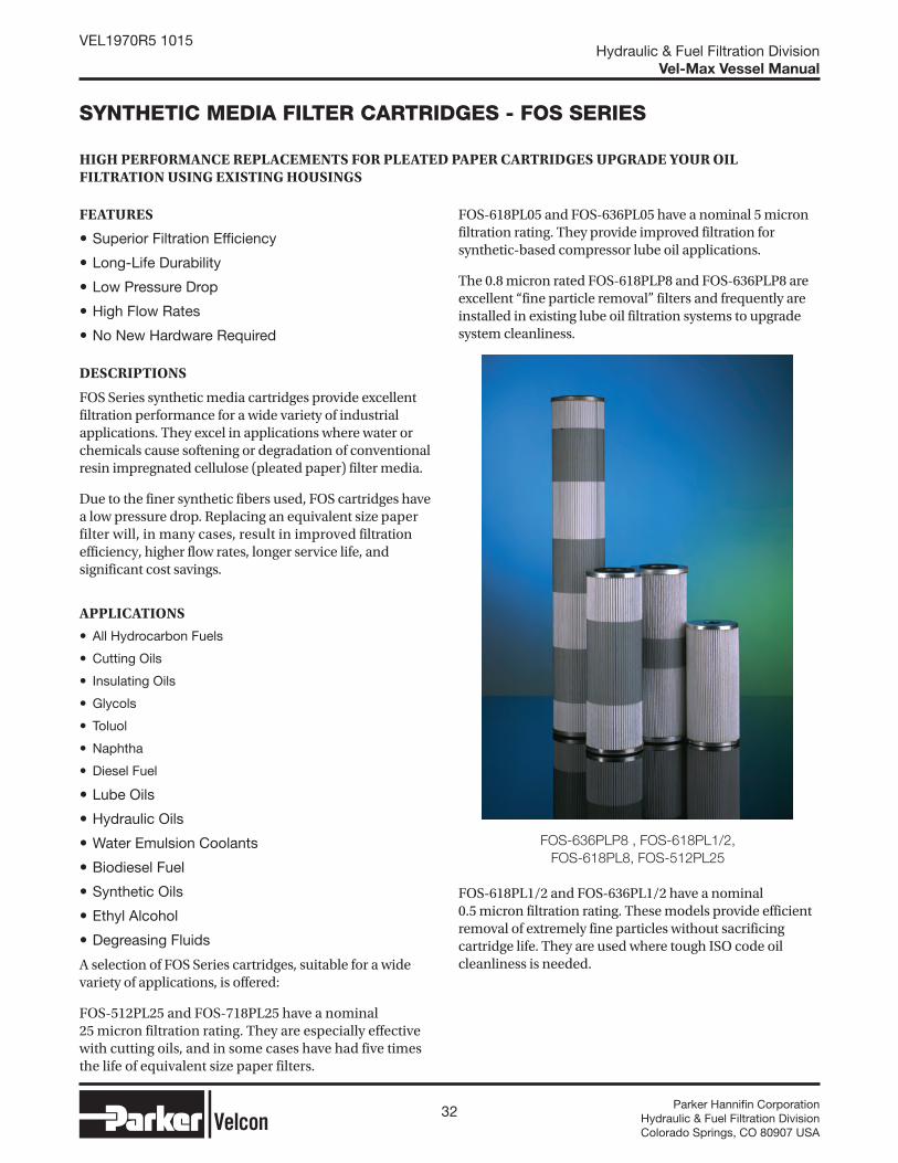
A selection of FOS Series cartridges, suitable for a wide variety of applications, is offered:
FOS-512PL25 and FOS-718PL25 have a nominal 25 micron filtration rating. They are especially effective with cutting oils, and in some cases have had five times the life of equivalent size paper filters.
FOS-618PL05 and FOS-636PL05 have a nominal 5 micron filtration rating. They provide improved filtration for synthetic-based compressor lube oil applications.
The 0.8 micron rated FOS-618PLP8 and FOS-636PLP8 are excellent “fine particle removal” filters and frequently are installed in existing lube oil filtration systems to upgrade system cleanliness.
FOS-618PL1/2 and FOS-636PL1/2 have a nominal 0.5 micron filtration rating. These models provide efficient removal of extremely fine particles without sacrificing cartridge life. They are used where tough ISO code oil cleanliness is needed.
FOS-636PLP8 , FOS-618PL1/2,
FOS-618PL8, FOS-512PL25

33 Parker Hannifi n CorporationHydraulic & Fuel Filtration DivisionColorado Springs, CO 80907 USA
Hydraulic & Fuel Filtration DivisionVel-Max Vessel Manual
VEL1970R5 1015
GENERAL SPECIFICATION
Collapse strength 75 psi
Max. Operating temperature 250°F
pH operating range 3 - 9
Recommended change-out at 25 psid differential pressure or after one year, whichever occurs first
Buna-N gasket material
Filter media are glass micro-fibers backed by spun-bonded polyester and metal screen. Twenty-five micron designs are spun-bonded polyester only.
Metal components are aluminized steel. FOS-512PL25 end caps are aluminum.
End cap bonding material is urethane.
CARTRIDGE SELECTION TABLE
Cartridge Model
O.D.(Inches)
I.D.(Inchec)
Length(Inches)
Surface Area (In.2)
Nominal(1) Rating
(Microns)Beta
Size(2) where
Beta=75
ACFTD Capacity
(GMS)
FOS-512PL25 55/8 n.a. 12¼ 2390 25 n.a. 60 210
FOS-718PL25 6¼ 29⁄16 18 3970 25 n.a. 60 360
FOS-618PL05 6 29⁄16 18 2000 5 3.5 37 172
FOS-618PLP8 6 29⁄16 18 2000 0.8 90 8 87
FOS-618PL1/2 6 29⁄16 18 2000 ½ 250 4 71
FOS-636PL05 6 29⁄16 36 4160 5 3.5 37 358
FOS-636PLP8 6 29⁄16 36 4160 0.8 90 8 180
FOS-636PL1/2 6 29⁄16 36 4160 ½ 250 4 148
NOTES: (1)Nominal gravimetric filter micron rating.(2) Particle size (microns) where Beta equals 75. Often referred to as the “absolute” rating of the cartridge.
34 Parker Hannifi n CorporationHydraulic & Fuel Filtration DivisionColorado Springs, CO 80907 USA
Hydraulic & Fuel Filtration DivisionVel-Max Vessel Manual
VEL1970R5 1015
OPERATION OF VESSELS CONTAINING WATER ABSORBING CARTRIDGES (ACO/ACI/CDF®) FOR AVIATION FUEL
NOTE IF PUMP DISCHARGE PRESSURE CAN EXCEED 25 PSI, DO NOT USE THIS CARTRIDGE UNLESS PRESSURE GAUGES ARE INSTALLED TO MEASURE THE DIFFERENTIAL PRESSURE. FOR ALL SYSTEMS, DIFFERENTIAL PRESSURE GAUGES ARE STRONGLY RECOMMENDED, ALONG WITH DAILY MONITORING OF DP. IF THE GAUGES CANNOT BE OBSERVED EASILY DURING FLOW, AN ELECTRONIC MONITORING METHOD, WITH FLOW SHUTDOWN CAPABILITY, IS RECOMMENDED.
NOTE ALWAYS ENSURE THAT THE VESSEL AND DRAIN PLUG ARE PROPERLY GROUNDED. IF THE AQUACON® CARTRIDGE ACOXXXXX IS USED IN A VF31E, VF61, VF61E, OR VF609 OR SIMILAR SIZED HOUSINGS, PLEASE REFER TO THE INSTRUCTIONS FOR THE HOUSINGS IN WHICH CARTRIDGES ARE INSTALLED FOR MORE INFORMATION.
Contact Parker Hydraulic & Fuel Filtration Division for more information.
RECOMMENDED PROCEDURES* TO FOLLOW WITH WATER ABSORBING CARTRIDGES IN A VESSEL:
Quality Control Checks.Reinforce quality control checks and diligently conduct water removal procedures at all locations in the fuel distribution system. This includes daily draining of all sumps, low points, and dead legs in the piping system.
Monitor dP DailyIf operating at reduced flow, record differential pressure and flow rate and calculate normalized differential pressure. (See page 2). Change
ACO, ACI, & CDF® cartridges when normalized
differential pressure reaches 25 psid**. Replace all
cartridges if the normalized differential pressure
has dropped 5 psid below the previous reading.
Check for Free Water Content.Sample fuel and check for free water content using the Parker Velcon Hydrokit® or other chemical method in accordance with your company’s fuel handling procedures. Replace cartridges if the water content exceeds your company guidelines.
EI Monitor Spec. 1583.In converted filter/separator vessels where the deckplate or manifold strength does not meet the 15 bar (220 psi) strength required by the EI Monitor Spec. 1583, a differential pressure limiting device, set from 25-30 psid, should be installed across the vessel.
Spare Water Absorbing Cartridge.Have a spare set of water absorbing cartridges on hand, or available at a nearby Parker Velcon Distributor, for the unexpected plug-up.
Confirm dP if Operating below 50%.If fueling unit is operating consistently below 50% of rated flow then periodically check fueling unit at test stand and check DP at flow rate of 50% or higher and confirm corrected DP.
Check for Fibers and Hose End Strainers.After changing cartridges circulate flow through vessel for at least 3 minutes, use millipores to check for fibers and also check hose end strainers.
Cartridge Restricting Flow.As the cartridges begin to restrict the flow due to a water slug, ALL upstream and downstream piping should be checked and purged before resuming operations with a new set of cartridges. Any aircraft involved in fueling when the flow through a cartridge is restricted, should also be checked for the possibility of water reaching the aircraft. Check the tank to determine where the excess water came from, and purge the tank of any water before resuming operation.
Cartridges should not be dried and re-used.When water saturated media is dried, it may shrink and crack, leading to possible internal bypass.
*Please also check with your company’s fuel handling guidelines and operating procedures.
**ATA 103 compliance now requires 15 psid normalized differential pressure changeout.

35 Parker Hannifi n CorporationHydraulic & Fuel Filtration DivisionColorado Springs, CO 80907 USA
Hydraulic & Fuel Filtration DivisionVel-Max Vessel Manual
VEL1970R5 1015
SERVICE LIFE
Service life for all water absorbing cartridges, including two (2), five (5) and six (6) inch diameter cartridges, should be one (1) year, unless stated otherwise by your company’s fuel handling procedures.
CAUTION
do not use water absorbing cartridges with pre-mixed jet fuel containing anti-icing additives
WARNING
ABSORBENTTYPE MONITOR CARTRIDGES WILL NOT REMOVE WATER FROM FUEL CONTAINING ALCOHOLBLENDING AGENTS COMMONLY CALLED GASOHOL. FOR REMOVAL OF SOLIDS, PLEASE USE PARKER VELCON PARTICLE REMOVAL FILTERS SPECIFICALLY MADE FOR GASOHOL. CONSULT YOUR PARKER VELCON REPRESENTATIVE.
For technical support, contact Parker Hydraulic & Fuel Filtration Division or your authorized Parker Velcon distributor. Also visit us on-line at www.velcon.com
Ves
sel D
iff e
ren
tial
Pre
ssu
re (
psi
d)
Percent of Rated Flow (or Percent of System Flow Limit)
Change cartridges for readings above curve.
Do not change cartridges for readings below curve.
25 psid Changeout Curve
15 psid Changeout
Curve*
Decal #1846 - Cartridge Changeout Curve for cartridges with 25 psid changeout requirements*Decal #1979 - Cartridge Changeout Curve for cartridges with 15 psid changeout requirement (per ATA 103)
EXAMPLE: (25 psid changeout) A 600 GPM monitor vessel is operating at 300 GPM (50% of system flow limit). If the pressure differential is less than 8 psid, the cartridges do not require changing; however, if the pressure differential is 8 psid or more, or if the cartridges have been in service for one year, the cartridges are due for changeout.
(15 psi changeout) For the same vessel, at 50% of system flow limit, if the pressure differential is less than 6.5 psid, do not change the cartridges; however, if the pressure differential is 6.5 psid or more, or after one year of service, the cartridges are due for changeout.
CARTRIDGE CHANGEOUT CURVESSPENT CARTRIDGES AT REDUCED FLOW RATES

Parker Hannifi n CorporationHydraulic & Fuel Filtration Division
1210 Garden of the Gods RoadColorado Springs, CO 80907phone +1 719 531 5855www.velcon.com
© 2013 Parker Hannifi n Corporation. Product names are trademarks or registered trademarks of their respective companies. VEL1970R4 06/13