Vehicle Restraint System Manual Vehicle Restraint Manual.pdf · Trinity Low Profile Vehicle...
46
Trinity Low Profile Vehicle Restraint System Through Track Mandrel (TTM) Pre-Trip, Installation, Removal, and Field Repair Manual Revision 1 – July 15, 2015 Trinity Parts & Components, LLC 2525 N. Stemmons Freeway Dallas, TX 75207 Phone: (800) 631-4420 Fax: (214) 589-8171 © 2015 Trinity Parts & Components, LLC This document is property of Trinity Parts & Components, LLC, and should only be used in connection with Trinity Low Profile Vehicle Restraint System. Any modification, reproduction, or alteration without the express written permission of Trinity Parts & Components, LLC is strictly prohibited.
-
Upload
truongkiet -
Category
Documents
-
view
229 -
download
2
Transcript of Vehicle Restraint System Manual Vehicle Restraint Manual.pdf · Trinity Low Profile Vehicle...
Trinity Low Profile Vehicle Restraint System Through Track Mandrel (TTM)
Pre-Trip, Installation, Removal, and Field Repair Manual
Revision 1 – July 15, 2015
Trinity Parts & Components, LLC 2525 N. Stemmons Freeway
Dallas, TX 75207 Phone: (800) 631-4420
Fax: (214) 589-8171
© 2015 Trinity Parts & Components, LLC
This document is property of Trinity Parts & Components, LLC, and should only be used in connection with Trinity Low Profile Vehicle Restraint System. Any modification, reproduction, or alteration without the express
written permission of Trinity Parts & Components, LLC is strictly prohibited.
Vehicle Restraint System Manual
Revision 1 Page 2 July 15, 2015
Table of Contents Introduction ..................................................................................................................... 3 Cautions and Notices ...................................................................................................... 4 Pre-Trip Inspection .......................................................................................................... 6 Installation Instructions .................................................................................................... 8 Removal Instructions ..................................................................................................... 13 Field Repairs ................................................................................................................. 17
Replacing a Damaged Strap ...................................................................................... 17 Replacing Damaged or Missing Polymer Rings: ........................................................ 18 Replacing a Broken Torsion Spring ........................................................................... 19 Replacing a Damaged or Worn Ratchet Release Lever: ............................................ 19 Replacing a Track Retainer Lock Spring .................................................................... 20 Replacing a Damaged or Worn Track Retainer Lock and Clevis Pin .......................... 21 Replacing the End Cap .............................................................................................. 21 Replacing a Worn or Damaged Pin End Roller Assembly .......................................... 22 Replacing a Bent Ratchet Mandrel: ........................................................................... 23 Replacing a Bent Anchor Mandrel: ............................................................................ 26
Assembly Procedures ................................................................................................... 28 Anchor Restraint and Strap Assembly Procedure ...................................................... 28
Apply Polymer Rings and Strap Assembly to Anchor Mandrel ............................................. 28 Apply Lock Lever, Spring, and Clevis Pin to Retainer Casting ............................................. 30 Assemble Anchor Mandrel and Retainer Casting ................................................................. 33
Ratchet Restraint Assembly Procedure ..................................................................... 35 Apply Polymer Rings and Tire Guard to Ratchet Mandrel .................................................... 35 Apply Lock Lever, Spring, and Clevis Pin, to Retainer Casting ............................................ 36 Apply Release Lever, Torsion Spring, and Shoulder Bolt to Retainer Casting ..................... 38 Assemble Ratchet Mandrel, Retainer Casting, Ratchet, and End Cap ................................. 39
Parts Lists – Anchor and Ratchet Restraints ................................................................. 42 Anchor Restraint Parts List ........................................................................................ 42 Ratchet Restraint Parts List ....................................................................................... 42
Engineering Drawings ................................................................................................... 43 Ratchet Restraint Exploded (Drawing Number EXP_RATCHET) ............................... 43 Anchor Restraint Exploded (Drawing Number EXP_ANCHOR) ................................. 44 Restraints & Strap Assembly (Drawing Number M-099-7083) ................................... 45
Service, Parts, and Rebuilding ...................................................................................... 46
Vehicle Restraint System Manual
Revision 1 Page 3 July 15, 2015
Introduction
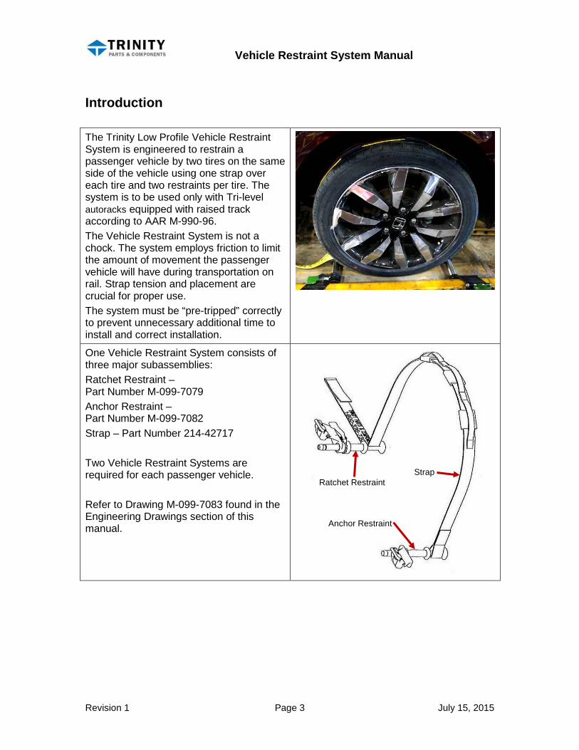
The Trinity Low Profile Vehicle Restraint System is engineered to restrain a passenger vehicle by two tires on the same side of the vehicle using one strap over each tire and two restraints per tire. The system is to be used only with Tri-level autoracks equipped with raised track according to AAR M-990-96. The Vehicle Restraint System is not a chock. The system employs friction to limit the amount of movement the passenger vehicle will have during transportation on rail. Strap tension and placement are crucial for proper use. The system must be “pre-tripped” correctly to prevent unnecessary additional time to install and correct installation.
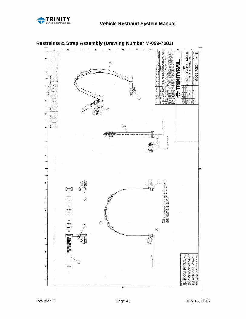
One Vehicle Restraint System consists of three major subassemblies: Ratchet Restraint – Part Number M-099-7079 Anchor Restraint – Part Number M-099-7082 Strap – Part Number 214-42717 Two Vehicle Restraint Systems are required for each passenger vehicle. Refer to Drawing M-099-7083 found in the Engineering Drawings section of this manual.
Ratchet Restraint
Strap
Anchor Restraint
Vehicle Restraint System Manual
Revision 1 Page 4 July 15, 2015
Cautions and Notices
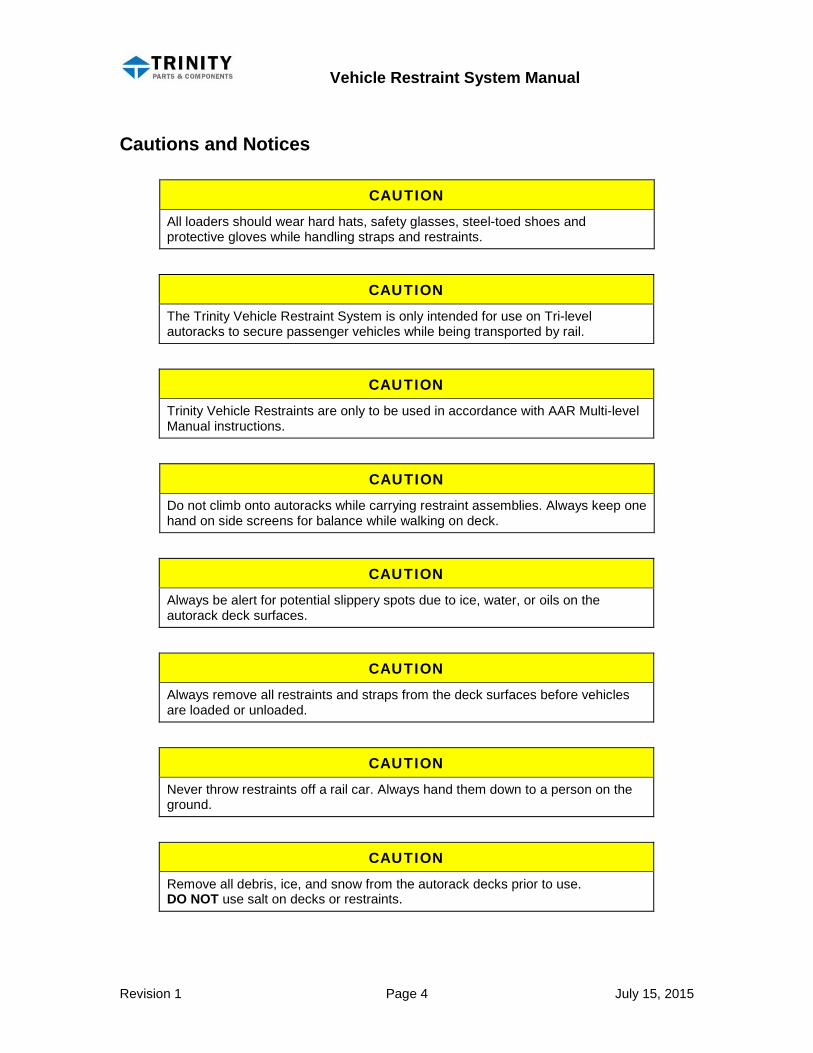
CAUTION
All loaders should wear hard hats, safety glasses, steel-toed shoes and protective gloves while handling straps and restraints.
CAUTION
The Trinity Vehicle Restraint System is only intended for use on Tri-level autoracks to secure passenger vehicles while being transported by rail.
CAUTION
Trinity Vehicle Restraints are only to be used in accordance with AAR Multi-level Manual instructions.
CAUTION
Do not climb onto autoracks while carrying restraint assemblies. Always keep one hand on side screens for balance while walking on deck.
CAUTION
Always be alert for potential slippery spots due to ice, water, or oils on the autorack deck surfaces.
CAUTION
Always remove all restraints and straps from the deck surfaces before vehicles are loaded or unloaded.
CAUTION
Never throw restraints off a rail car. Always hand them down to a person on the ground.
CAUTION
Remove all debris, ice, and snow from the autorack decks prior to use. DO NOT use salt on decks or restraints.
Vehicle Restraint System Manual
Revision 1 Page 5 July 15, 2015
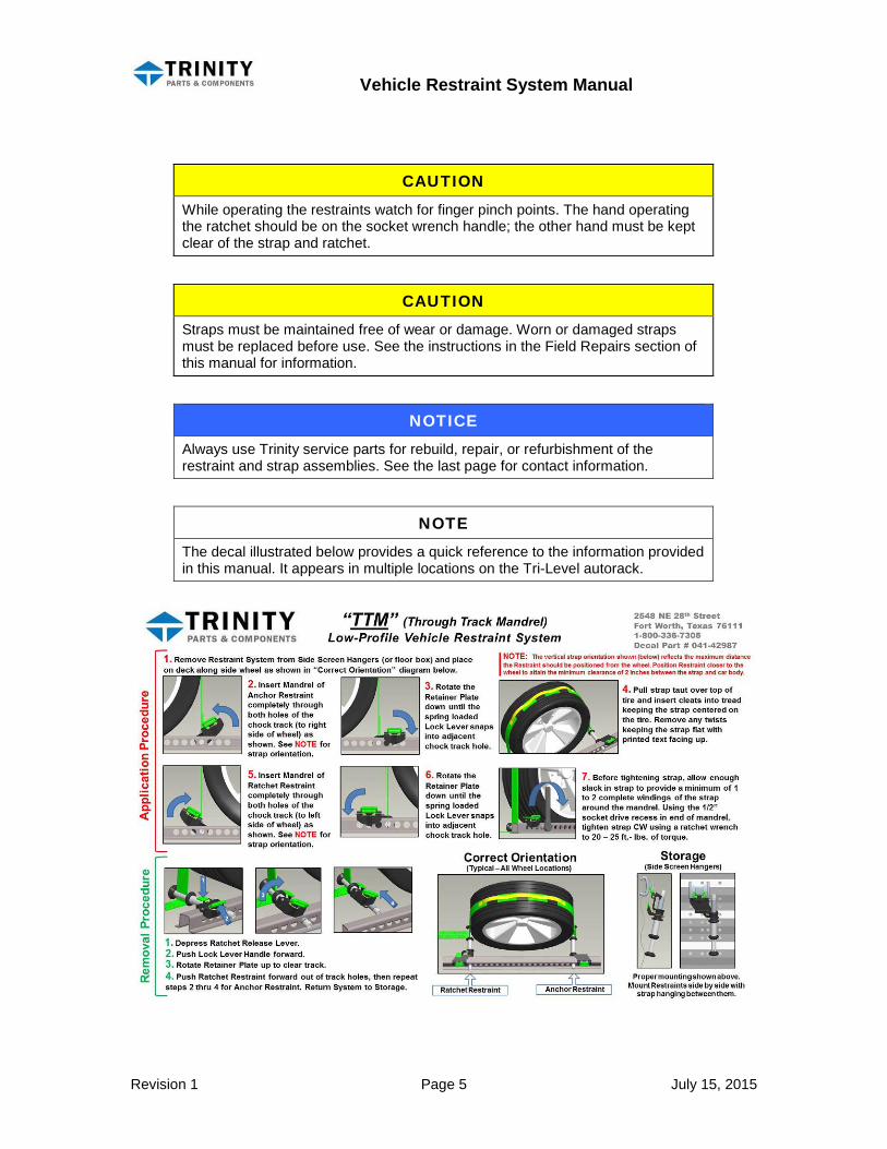
CAUTION
While operating the restraints watch for finger pinch points. The hand operating the ratchet should be on the socket wrench handle; the other hand must be kept clear of the strap and ratchet.
CAUTION Straps must be maintained free of wear or damage. Worn or damaged straps must be replaced before use. See the instructions in the Field Repairs section of this manual for information.
NOTICE Always use Trinity service parts for rebuild, repair, or refurbishment of the restraint and strap assemblies. See the last page for contact information.
NOTE The decal illustrated below provides a quick reference to the information provided in this manual. It appears in multiple locations on the Tri-Level autorack.

Vehicle Restraint System Manual
Revision 1 Page 6 July 15, 2015
Pre-Trip Inspection
CAUTION
Refer to the Cautions section at the beginning of this manual.
Two Vehicle Restraint Systems are required to control a vehicle. The systems are to be stored off the deck either in chock boxes or on provided hangers, if so equipped.
Do not use salt on the decks of an auto rack equipped with this system. The Trinity Vehicle Restraint System has premium coatings to prevent corrosion, but ease of operation and Restraint life will be extended if salt or other known corrosive ice melt is not used. Refer to Multi-level manual for allowable ice and snow removal procedures.
Restraints immobilized due to ice can be freed by inserting them into the chock track and latching the retainer body down. Then rotate the Restraint with a ½” square drive ratchet wrench in the clockwise direction [ ] (as seen by the operator) and the Restraint will be freed.
CAUTION Do not hammer the end of the restraint assembly against a rack post. This will deform and damage the end of the restraint roller assembly and prevent proper operation.
Inspect Vehicle Restraints for damage and replace if necessary according to AAR requirements. The Vehicle Restraint System does not require lubrication.

Vehicle Restraint System Manual
Revision 1 Page 7 July 15, 2015
The straps should not be twisted or wrapped around the Restraints. Untwist the strap so that the cleats will face towards the tire tread.
Unwind the strap so that the strap end will slide freely through the slot in the Ratchet Restraint. Straps must be stored close to the side screen to prevent them catching on the vehicles’ side mirrors.

Vehicle Restraint System Manual
Revision 1 Page 8 July 15, 2015
Installation Instructions
CAUTION
Refer to the Cautions section at the beginning of this manual.
Vehicle Restraint Systems shall be properly stored prior to loading. Refer to the Pre-Trip Inspection section of this manual. Vehicle Restraints should never be driven over; damage to tires, the vehicle and the restraint may occur. Vehicle Restraint Systems may be hung on side screen hangers or stored in existing chock boxes if the chock boxes have bottoms. Do not place Restraints in chock boxes without bottoms because they could slip out and fall between decks and out of the rail car.
Vehicles are to be positioned so that the sides of the tires are ½" to 2” from the chock track. The ideal vehicle position allows the Restraint Strap to extend vertically from the attachment point on the Restraint over the center line of the tire.
Vehicle Restraint System Manual
Revision 1 Page 9 July 15, 2015
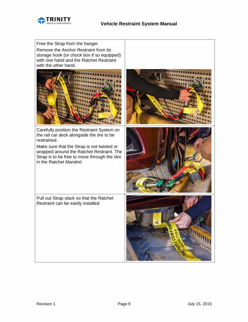
Free the Strap from the hanger. Remove the Anchor Restraint from its storage hook (or chock box if so equipped) with one hand and the Ratchet Restraint with the other hand.
Carefully position the Restraint System on the rail car deck alongside the tire to be restrained. Make sure that the Strap is not twisted or wrapped around the Ratchet Restraint. The Strap is to be free to move through the slot in the Ratchet Mandrel.
Pull out Strap slack so that the Ratchet Restraint can be easily installed.
Vehicle Restraint System Manual
Revision 1 Page 10 July 15, 2015
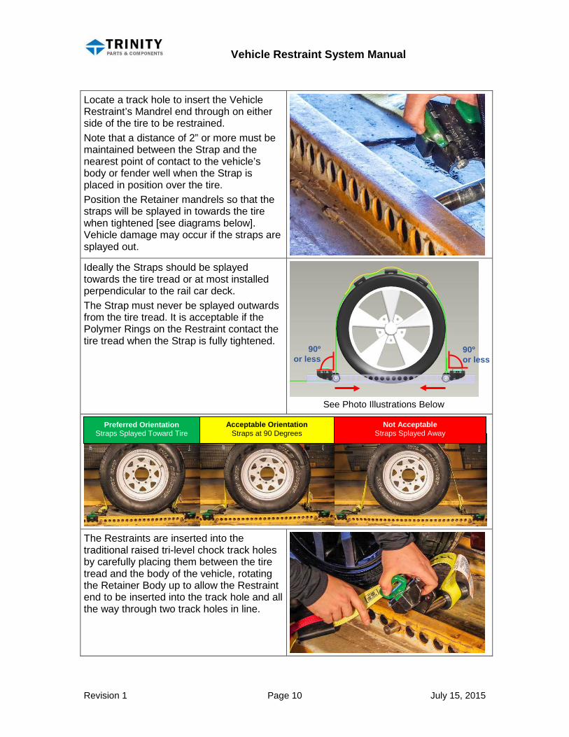
Locate a track hole to insert the Vehicle Restraint’s Mandrel end through on either side of the tire to be restrained. Note that a distance of 2” or more must be maintained between the Strap and the nearest point of contact to the vehicle’s body or fender well when the Strap is placed in position over the tire. Position the Retainer mandrels so that the straps will be splayed in towards the tire when tightened [see diagrams below]. Vehicle damage may occur if the straps are splayed out. Ideally the Straps should be splayed towards the tire tread or at most installed perpendicular to the rail car deck. The Strap must never be splayed outwards from the tire tread. It is acceptable if the Polymer Rings on the Restraint contact the tire tread when the Strap is fully tightened.
The Restraints are inserted into the traditional raised tri-level chock track holes by carefully placing them between the tire tread and the body of the vehicle, rotating the Retainer Body up to allow the Restraint end to be inserted into the track hole and all the way through two track holes in line.
90º or less
90º or less
Preferred Orientation Straps Splayed Toward Tire
Acceptable Orientation Straps at 90 Degrees
Not Acceptable Straps Splayed Away
See Photo Illustrations Below
Vehicle Restraint System Manual
Revision 1 Page 11 July 15, 2015
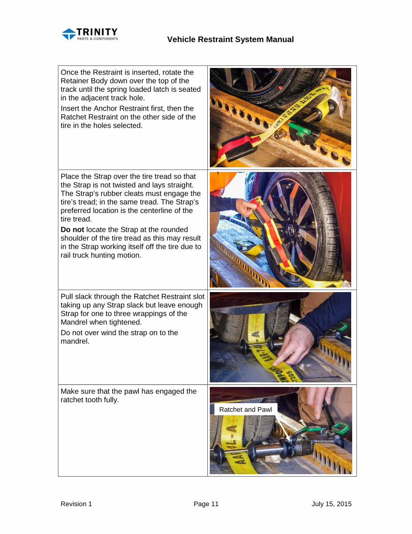
Once the Restraint is inserted, rotate the Retainer Body down over the top of the track until the spring loaded latch is seated in the adjacent track hole. Insert the Anchor Restraint first, then the Ratchet Restraint on the other side of the tire in the holes selected.
Place the Strap over the tire tread so that the Strap is not twisted and lays straight. The Strap’s rubber cleats must engage the tire’s tread; in the same tread. The Strap’s preferred location is the centerline of the tire tread. Do not locate the Strap at the rounded shoulder of the tire tread as this may result in the Strap working itself off the tire due to rail truck hunting motion.
Pull slack through the Ratchet Restraint slot taking up any Strap slack but leave enough Strap for one to three wrappings of the Mandrel when tightened. Do not over wind the strap on to the mandrel.
Make sure that the pawl has engaged the ratchet tooth fully.
Ratchet and Pawl

Vehicle Restraint System Manual
Revision 1 Page 12 July 15, 2015
Tighten the Strap using a ½” square drive hand ratchet wrench a minimum of 25 Ft. Lbs. while using your left hand to pull the tail of the strap to prevent it from being wrapped over the Polymer Rings. The Strap tightens in the clockwise [ ] direction as viewed from the end of the Mandrel. A ½” square drive extension may be used to increase the wrench swing.
Excess Strap can be tucked under the Ratchet Restraint if necessary.
A correctly installed Restraint System will prevent vehicle damage and deliver a damage-free vehicle to a satisfied customer.
Tighten
Vehicle Restraint System Manual
Revision 1 Page 13 July 15, 2015
Removal Instructions
CAUTION
Refer to the Cautions section at the beginning of this manual.
To remove the Vehicle Restraint System from each automobile on the Auto Rack:
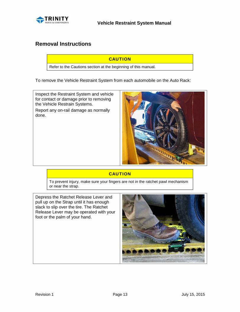
Inspect the Restraint System and vehicle for contact or damage prior to removing the Vehicle Restrain Systems. Report any on-rail damage as normally done.
CAUTION
To prevent injury, make sure your fingers are not in the ratchet pawl mechanism or near the strap.
Depress the Ratchet Release Lever and pull up on the Strap until it has enough slack to slip over the tire. The Ratchet Release Lever may be operated with your foot or the palm of your hand.
Vehicle Restraint System Manual
Revision 1 Page 14 July 15, 2015
If necessary, reposition the vehicle off the Polymer Rings on the Restraint if the vehicle has shifted during transportation in order to remove the Strap or Restraints.
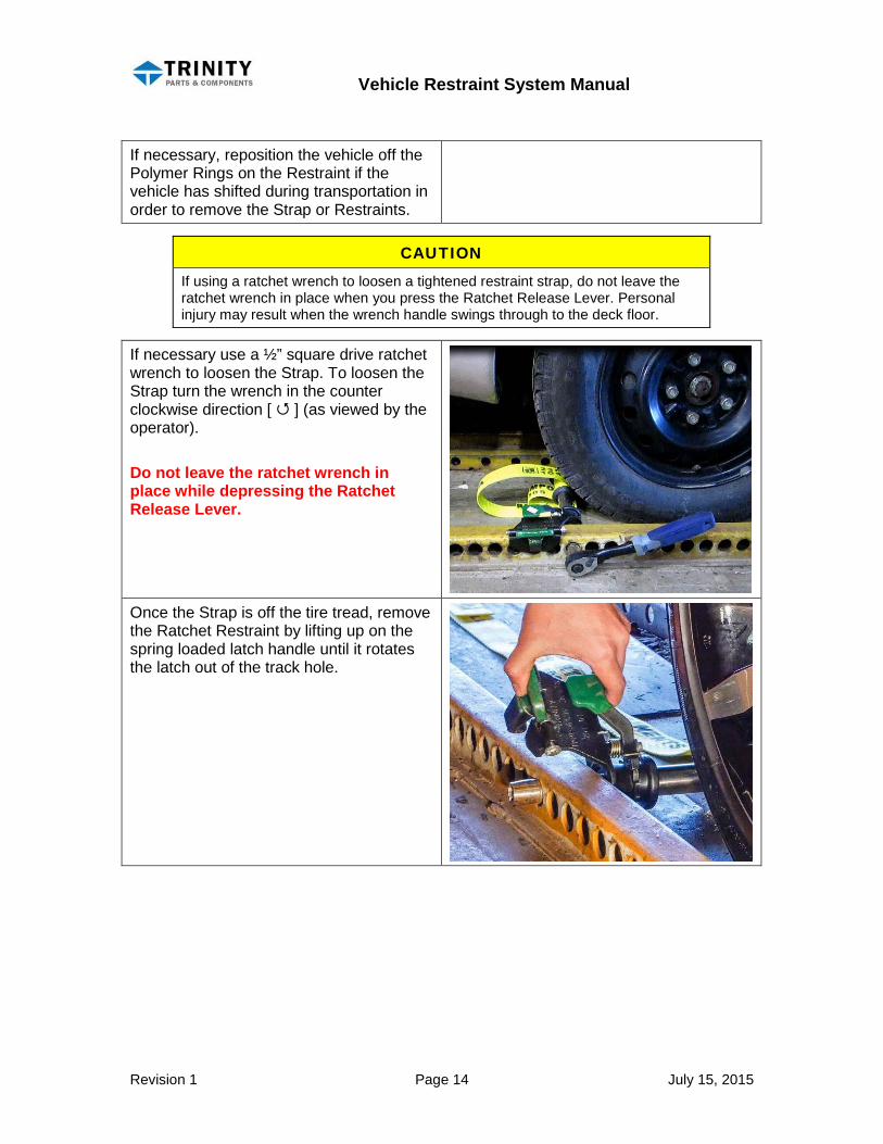
CAUTION If using a ratchet wrench to loosen a tightened restraint strap, do not leave the ratchet wrench in place when you press the Ratchet Release Lever. Personal injury may result when the wrench handle swings through to the deck floor.
If necessary use a ½” square drive ratchet wrench to loosen the Strap. To loosen the Strap turn the wrench in the counter clockwise direction [ ] (as viewed by the operator). Do not leave the ratchet wrench in place while depressing the Ratchet Release Lever.
Once the Strap is off the tire tread, remove the Ratchet Restraint by lifting up on the spring loaded latch handle until it rotates the latch out of the track hole.
Vehicle Restraint System Manual
Revision 1 Page 15 July 15, 2015
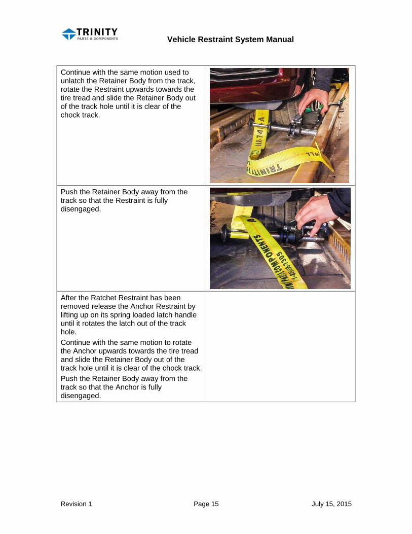
Continue with the same motion used to unlatch the Retainer Body from the track, rotate the Restraint upwards towards the tire tread and slide the Retainer Body out of the track hole until it is clear of the chock track.
Push the Retainer Body away from the track so that the Restraint is fully disengaged.
After the Ratchet Restraint has been removed release the Anchor Restraint by lifting up on its spring loaded latch handle until it rotates the latch out of the track hole. Continue with the same motion to rotate the Anchor upwards towards the tire tread and slide the Retainer Body out of the track hole until it is clear of the chock track. Push the Retainer Body away from the track so that the Anchor is fully disengaged.
Vehicle Restraint System Manual
Revision 1 Page 16 July 15, 2015
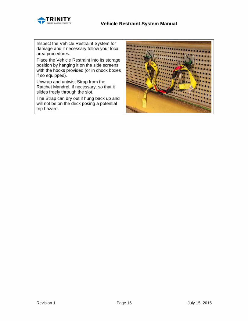
Inspect the Vehicle Restraint System for damage and if necessary follow your local area procedures. Place the Vehicle Restraint into its storage position by hanging it on the side screens with the hooks provided (or in chock boxes if so equipped). Unwrap and untwist Strap from the Ratchet Mandrel, if necessary, so that it slides freely through the slot. The Strap can dry out if hung back up and will not be on the deck posing a potential trip hazard.

Vehicle Restraint System Manual
Revision 1 Page 17 July 15, 2015
Field Repairs
CAUTION
Refer to the Cautions section at the beginning of this manual.
CAUTION Wear safety glasses and other personal protection equipment (PPE) as required by your employer when performing these procedures.
NOTE Part numbers in parentheses ( ) refer to Trinity service parts for replacement, repair, or refurbishment of the Restraint and Strap assemblies.
NOTE If greater detail is necessary during reassembly refer to the Assembly Procedures sections in the back of this manual.
The Vehicle Restraint System can be easily rebuilt in the field.
Replacing a Damaged Strap Remove damaged Strap by aligning the flap at the end of the strap and sliding it through the slot on the Ratchet Mandrel. Before removing the Polymer Rings note the orientation of the rings for reinstallation later. Remove the Polymer Ring at the end of the Anchor Restraint using your hands. Slide looped end of the strap off the Mandrel. Acquire a new Strap (214-42717). Slide the looped end of the Strap onto the Anchor Restraint.
Inspect the Anchor Restraint Polymer Ring. If it is damaged or worn acquire a new Ring (M-999-7147).
Vehicle Restraint System Manual
Revision 1 Page 18 July 15, 2015
If necessary, apply a small amount of liquid dish soap to the Anchor Restraint to help with lubrication. Carefully slide the Polymer Ring onto the Restraint until it is positioned on the outermost end. Use a rag to wipe any excess soap lubricant off the Anchor Restraint.
Reinstall the Strap on the Ratchet Restraint by aligning the flap at the end of the Strap and sliding it through the slot on the Restraint. Pull out enough excess Strap to assure it will not pull loose.
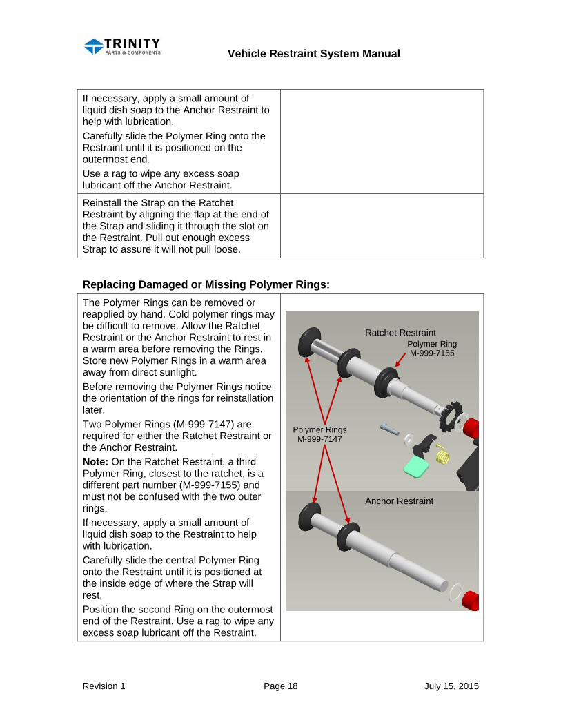
Replacing Damaged or Missing Polymer Rings: The Polymer Rings can be removed or reapplied by hand. Cold polymer rings may be difficult to remove. Allow the Ratchet Restraint or the Anchor Restraint to rest in a warm area before removing the Rings. Store new Polymer Rings in a warm area away from direct sunlight. Before removing the Polymer Rings notice the orientation of the rings for reinstallation later. Two Polymer Rings (M-999-7147) are required for either the Ratchet Restraint or the Anchor Restraint. Note: On the Ratchet Restraint, a third Polymer Ring, closest to the ratchet, is a different part number (M-999-7155) and must not be confused with the two outer rings. If necessary, apply a small amount of liquid dish soap to the Restraint to help with lubrication. Carefully slide the central Polymer Ring onto the Restraint until it is positioned at the inside edge of where the Strap will rest. Position the second Ring on the outermost end of the Restraint. Use a rag to wipe any excess soap lubricant off the Restraint.
Polymer Rings M-999-7147
Polymer Ring M-999-7155
Ratchet Restraint
Anchor Restraint
Vehicle Restraint System Manual
Revision 1 Page 19 July 15, 2015
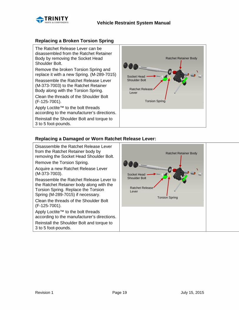
Replacing a Broken Torsion Spring The Ratchet Release Lever can be disassembled from the Ratchet Retainer Body by removing the Socket Head Shoulder Bolt. Remove the broken Torsion Spring and replace it with a new Spring. (M-289-7015) Reassemble the Ratchet Release Lever (M-373-7003) to the Ratchet Retainer Body along with the Torsion Spring. Clean the threads of the Shoulder Bolt (F-125-7001). Apply Loctite™ to the bolt threads according to the manufacturer’s directions. Reinstall the Shoulder Bolt and torque to 3 to 5 foot-pounds.
Replacing a Damaged or Worn Ratchet Release Lever: Disassemble the Ratchet Release Lever from the Ratchet Retainer body by removing the Socket Head Shoulder Bolt. Remove the Torsion Spring. Acquire a new Ratchet Release Lever (M-373-7003). Reassemble the Ratchet Release Lever to the Ratchet Retainer body along with the Torsion Spring. Replace the Torsion Spring (M-289-7015) if necessary. Clean the threads of the Shoulder Bolt (F-125-7001). Apply Loctite™ to the bolt threads according to the manufacturer’s directions. Reinstall the Shoulder Bolt and torque to 3 to 5 foot-pounds.
Socket Head Shoulder Bolt
Torsion Spring
Ratchet Release Lever
Ratchet Retainer Body
Socket Head Shoulder Bolt
Torsion Spring
Ratchet Release Lever
Ratchet Retainer Body
Vehicle Restraint System Manual
Revision 1 Page 20 July 15, 2015
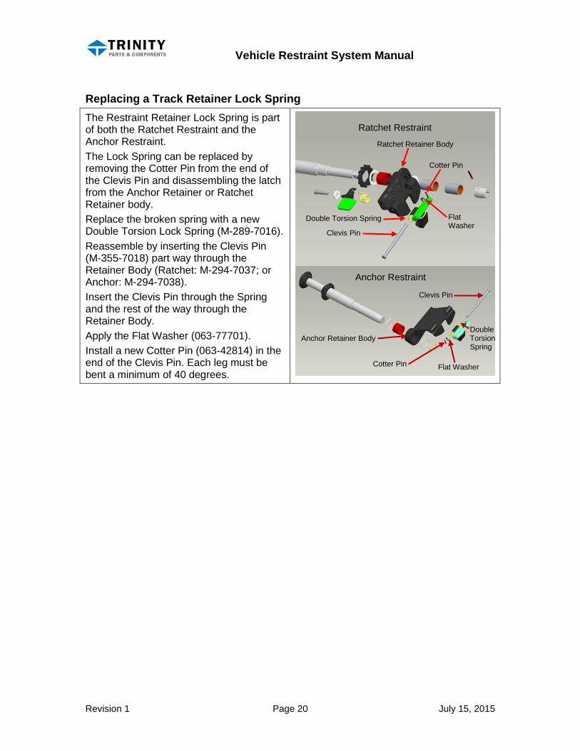
Replacing a Track Retainer Lock Spring The Restraint Retainer Lock Spring is part of both the Ratchet Restraint and the Anchor Restraint. The Lock Spring can be replaced by removing the Cotter Pin from the end of the Clevis Pin and disassembling the latch from the Anchor Retainer or Ratchet Retainer body. Replace the broken spring with a new Double Torsion Lock Spring (M-289-7016). Reassemble by inserting the Clevis Pin (M-355-7018) part way through the Retainer Body (Ratchet: M-294-7037; or Anchor: M-294-7038). Insert the Clevis Pin through the Spring and the rest of the way through the Retainer Body. Apply the Flat Washer (063-77701). Install a new Cotter Pin (063-42814) in the end of the Clevis Pin. Each leg must be bent a minimum of 40 degrees.
Ratchet Restraint
Anchor Restraint
Cotter Pin
Clevis Pin
Double Torsion Spring Flat Washer
Flat Washer
Clevis Pin
Double Torsion Spring
Cotter Pin
Anchor Retainer Body
Ratchet Retainer Body
Vehicle Restraint System Manual
Revision 1 Page 21 July 15, 2015
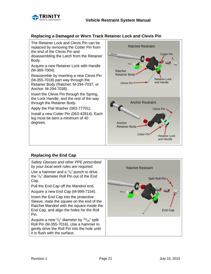
Replacing a Damaged or Worn Track Retainer Lock and Clevis Pin The Retainer Lock and Clevis Pin can be replaced by removing the Cotter Pin from the end of the Clevis Pin and disassembling the Latch from the Retainer Body. Acquire a new Retainer Lock with Handle (M-369-7004). Reassemble by inserting a new Clevis Pin (M-355-7018) part way through the Retainer Body (Ratchet: M-294-7037; or Anchor: M-294-7038). Insert the Clevis Pin through the Spring, the Lock Handle, and the rest of the way through the Retainer Body. Apply the Flat Washer (063-77701). Install a new Cotter Pin (063-42814). Each leg must be bent a minimum of 40 degrees.
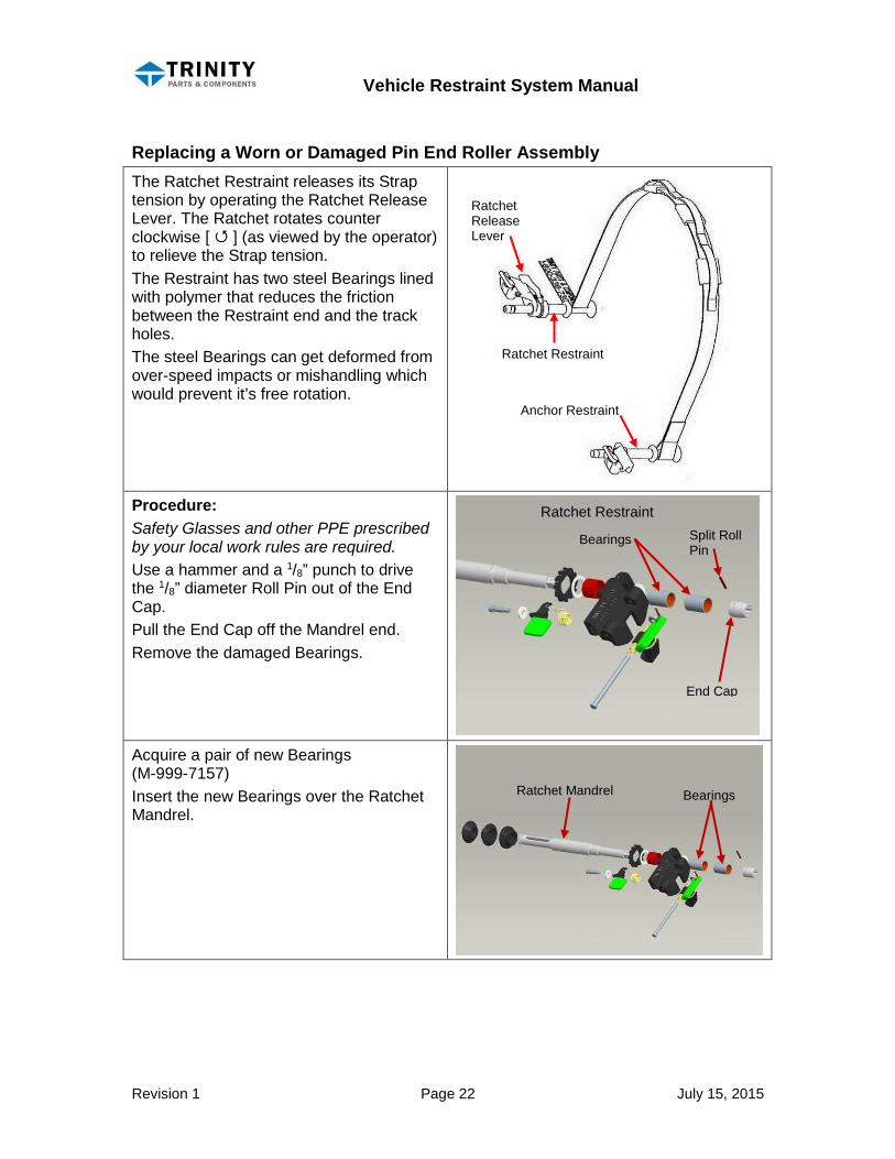
Replacing the End Cap Safety Glasses and other PPE prescribed by your local work rules are required. Use a hammer and a 1/8” punch to drive the 1/8” diameter Roll Pin out of the End Cap. Pull the End Cap off the Mandrel end. Acquire a new End Cap (M-999-7154). Insert the End Cap into the protective Sleeve, mate the square on the end of the Ratchet Mandrel with the square inside the End Cap, and align the holes for the Roll Pin. Acquire a new 1/8” diameter by 15/16” split Roll Pin (M-355-7016). Use a hammer to gently drive the Roll Pin into the hole until it is flush with the surface.
Ratchet Restraint
Anchor Restraint
Cotter Pin
Clevis Pin
Clevis Pin
Retainer Lock and Handle
Retainer Lock and Handle
Cotter Pin
Ratchet Restraint
End Cap
Split Roll Pin
Ratchet Retainer Body
Anchor Retainer Body
Vehicle Restraint System Manual
Revision 1 Page 22 July 15, 2015
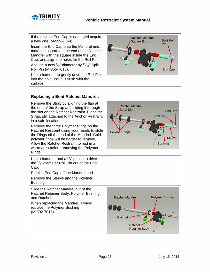
Replacing a Worn or Damaged Pin End Roller Assembly The Ratchet Restraint releases its Strap tension by operating the Ratchet Release Lever. The Ratchet rotates counter clockwise [ ] (as viewed by the operator) to relieve the Strap tension. The Restraint has two steel Bearings lined with polymer that reduces the friction between the Restraint end and the track holes. The steel Bearings can get deformed from over-speed impacts or mishandling which would prevent it’s free rotation.
Procedure: Safety Glasses and other PPE prescribed by your local work rules are required. Use a hammer and a 1/8” punch to drive the 1/8” diameter Roll Pin out of the End Cap. Pull the End Cap off the Mandrel end. Remove the damaged Bearings.
Acquire a pair of new Bearings (M-999-7157) Insert the new Bearings over the Ratchet Mandrel.
Ratchet Restraint Split Roll Pin
Bearings
End Cap
Ratchet Mandrel Bearings
Ratchet Restraint
Anchor Restraint
Ratchet Release Lever
Vehicle Restraint System Manual
Revision 1 Page 23 July 15, 2015
If the original End Cap is damaged acquire a new one (M-999-7154). Insert the End Cap onto the Mandrel end, mate the square on the end of the Ratchet Mandrel with the square inside the End Cap, and align the holes for the Roll Pin. Acquire a new 1/8” diameter by 15/16” Split Roll Pin (M-355-7016). Use a hammer to gently drive the Roll Pin into the hole until it is flush with the surface.
Replacing a Bent Ratchet Mandrel: Remove the Strap by aligning the flap at the end of the Strap and sliding it through the slot on the Ratchet Restraint. Place the Strap, still attached to the Anchor Restraint in a safe location. Remove the three Polymer Rings on the Ratchet Restraint using your hands to slide the Rings off the end of the Mandrel. Cold polymer rings will be harder to remove. Allow the Ratchet Restraint to rest in a warm area before removing the Polymer Rings.
Use a hammer and a 1/8” punch to drive the 1/8” diameter Roll Pin out of the End Cap. Pull the End Cap off the Mandrel end. Remove the Sleeve and the Polymer Bushing
Slide the Ratchet Mandrel out of the Ratchet Retainer Body, Polymer Bushing, and Ratchet. When replacing the Mandrel, always replace the Polymer Bushing (M-302-7013).
Ratchet Mandrel Square End
Split Roll Pin
End Cap
Ratchet Mandrel Strap Slot
Polymer Rings
Roll Pin
End Cap
Bushing
Sleeve
Ratchet Mandrel
Ratchet Retainer Body
Polymer Bushing
Ratchet
Vehicle Restraint System Manual
Revision 1 Page 24 July 15, 2015
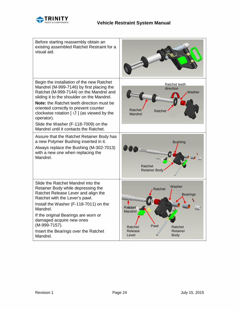
Before starting reassembly obtain an existing assembled Ratchet Restraint for a visual aid.
Begin the installation of the new Ratchet Mandrel (M-999-7146) by first placing the Ratchet (M-999-7144) on the Mandrel and sliding it to the shoulder on the Mandrel. Note: the Ratchet teeth direction must be oriented correctly to prevent counter clockwise rotation [ ] (as viewed by the operator). Slide the Washer (F-118-7009) on the Mandrel until it contacts the Ratchet.
Assure that the Ratchet Retainer Body has a new Polymer Bushing inserted in it. Always replace the Bushing (M-302-7013) with a new one when replacing the Mandrel.
Slide the Ratchet Mandrel into the Retainer Body while depressing the Ratchet Release Lever and align the Ratchet with the Lever’s pawl. Install the Washer (F-118-7011) on the Mandrel. If the original Bearings are worn or damaged acquire new ones (M-999-7157). Insert the Bearings over the Ratchet Mandrel.
Ratchet Mandrel
Ratchet
Washer
Ratchet Retainer Body
Bushing
Ratchet teeth direction
Ratchet Retainer Body
Bearings
Washer
Ratchet Release Lever
Pawl
Ratchet Mandrel
Ratchet

Vehicle Restraint System Manual
Revision 1 Page 25 July 15, 2015
Acquire a new End Cap if the original is damaged. (M-999-7154) Mate the square inside the End Cap with the square end of the Ratchet Mandrel and align the holes for the Roll Pin. Acquire a new 1/8” diameter x 15/16” split Roll Pin (M-355-7016). Use a hammer to gently drive the Roll Pin into the hole until it is flush with the surface.
Three Polymer Rings are required for the Ratchet Restraint. The innermost Ring, nearest the Ratchet, is part number (M-999-7155). The central Ring and the outer Ring are part number (M-999-7147) Apply a small amount of liquid dish soap to the Mandrel to help with lubrication.
Carefully slide the innermost Ring (M-999-7155) onto the Mandrel until it is positioned at the hub on the Mandrel. Carefully slide the central Ring (M-999-7147) onto the Mandrel until it is positioned at the inside edge of the Strap slot. Position the outer Ring (M-999-7147) on the end of the Mandrel. Use a rag to wipe any excess soap lubricant off the Mandrel.
Inspect the Strap for wear or damage. If it is not acceptable acquire a new Strap (214-42717). If it is necessary to replace the strap, use your hands to slide the outermost Polymer Ring off the end of the Anchor Restraint. Slide the old Strap loop off the Anchor Restraint and discard it appropriately.
Slide the new Strap loop over the Anchor Restraint and center it between the Polymer Ring positions. Replace the outer Ring on the end of the Anchor Restraint.
Ratchet Mandrel Square End
Split Roll Pin
End Cap
Polymer Rings M-999-7147
Polymer Ring M-999-7155
Vehicle Restraint System Manual
Revision 1 Page 26 July 15, 2015
Reinstall the Strap on the Ratchet Restraint by aligning the flap at the end of the Strap and sliding it through the slot on the Ratchet Mandrel. Pull out enough excess Strap to assure it will not pull loose.
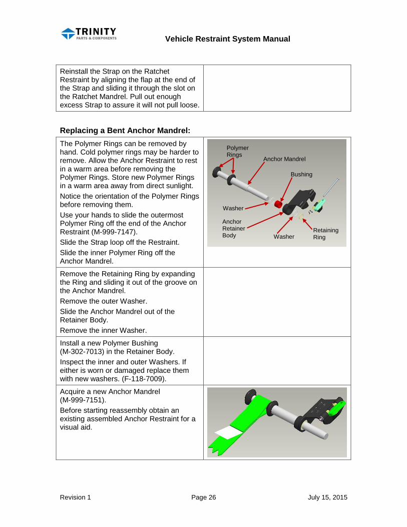
Replacing a Bent Anchor Mandrel: The Polymer Rings can be removed by hand. Cold polymer rings may be harder to remove. Allow the Anchor Restraint to rest in a warm area before removing the Polymer Rings. Store new Polymer Rings in a warm area away from direct sunlight. Notice the orientation of the Polymer Rings before removing them. Use your hands to slide the outermost Polymer Ring off the end of the Anchor Restraint (M-999-7147). Slide the Strap loop off the Restraint. Slide the inner Polymer Ring off the Anchor Mandrel.
Remove the Retaining Ring by expanding the Ring and sliding it out of the groove on the Anchor Mandrel. Remove the outer Washer. Slide the Anchor Mandrel out of the Retainer Body. Remove the inner Washer.
Install a new Polymer Bushing (M-302-7013) in the Retainer Body. Inspect the inner and outer Washers. If either is worn or damaged replace them with new washers. (F-118-7009).
Acquire a new Anchor Mandrel (M-999-7151). Before starting reassembly obtain an existing assembled Anchor Restraint for a visual aid.
Polymer Rings
Anchor Mandrel
Washer
Anchor Retainer Body
Bushing
Retaining Ring Washer
Vehicle Restraint System Manual
Revision 1 Page 27 July 15, 2015
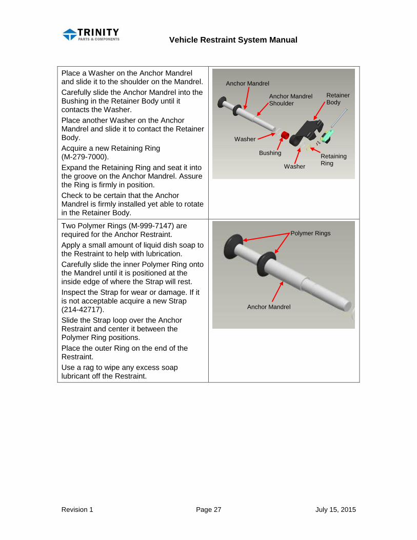
Place a Washer on the Anchor Mandrel and slide it to the shoulder on the Mandrel. Carefully slide the Anchor Mandrel into the Bushing in the Retainer Body until it contacts the Washer. Place another Washer on the Anchor Mandrel and slide it to contact the Retainer Body. Acquire a new Retaining Ring (M-279-7000). Expand the Retaining Ring and seat it into the groove on the Anchor Mandrel. Assure the Ring is firmly in position. Check to be certain that the Anchor Mandrel is firmly installed yet able to rotate in the Retainer Body.
Two Polymer Rings (M-999-7147) are required for the Anchor Restraint. Apply a small amount of liquid dish soap to the Restraint to help with lubrication. Carefully slide the inner Polymer Ring onto the Mandrel until it is positioned at the inside edge of where the Strap will rest. Inspect the Strap for wear or damage. If it is not acceptable acquire a new Strap (214-42717). Slide the Strap loop over the Anchor Restraint and center it between the Polymer Ring positions. Place the outer Ring on the end of the Restraint. Use a rag to wipe any excess soap lubricant off the Restraint.
Anchor Mandrel
Washer
Anchor Mandrel Shoulder
Retainer Body
Bushing
Washer
Retaining Ring
Polymer Rings
Anchor Mandrel
Vehicle Restraint System Manual
Revision 1 Page 28 July 15, 2015
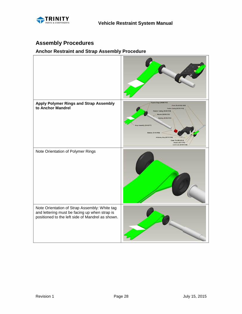
Assembly Procedures Anchor Restraint and Strap Assembly Procedure
Apply Polymer Rings and Strap Assembly to Anchor Mandrel
Note Orientation of Polymer Rings
Note Orientation of Strap Assembly: White tag and lettering must be facing up when strap is positioned to the left side of Mandrel as shown.
Vehicle Restraint System Manual
Revision 1 Page 29 July 15, 2015
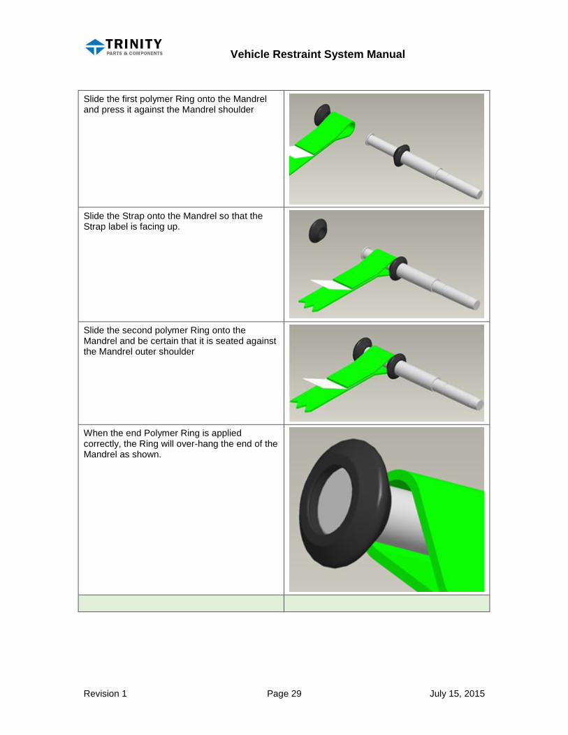
Slide the first polymer Ring onto the Mandrel and press it against the Mandrel shoulder
Slide the Strap onto the Mandrel so that the Strap label is facing up.
Slide the second polymer Ring onto the Mandrel and be certain that it is seated against the Mandrel outer shoulder
When the end Polymer Ring is applied correctly, the Ring will over-hang the end of the Mandrel as shown.
Vehicle Restraint System Manual
Revision 1 Page 30 July 15, 2015
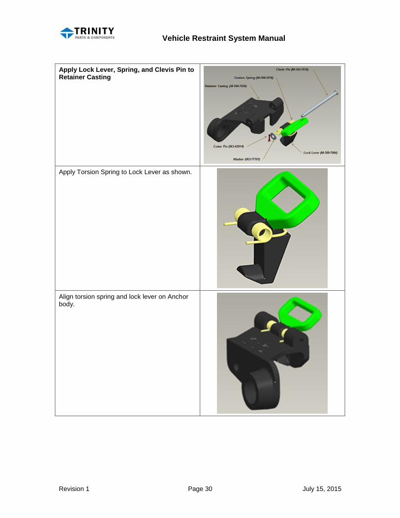
Apply Lock Lever, Spring, and Clevis Pin to Retainer Casting
Apply Torsion Spring to Lock Lever as shown.
Align torsion spring and lock lever on Anchor body.
Vehicle Restraint System Manual
Revision 1 Page 31 July 15, 2015
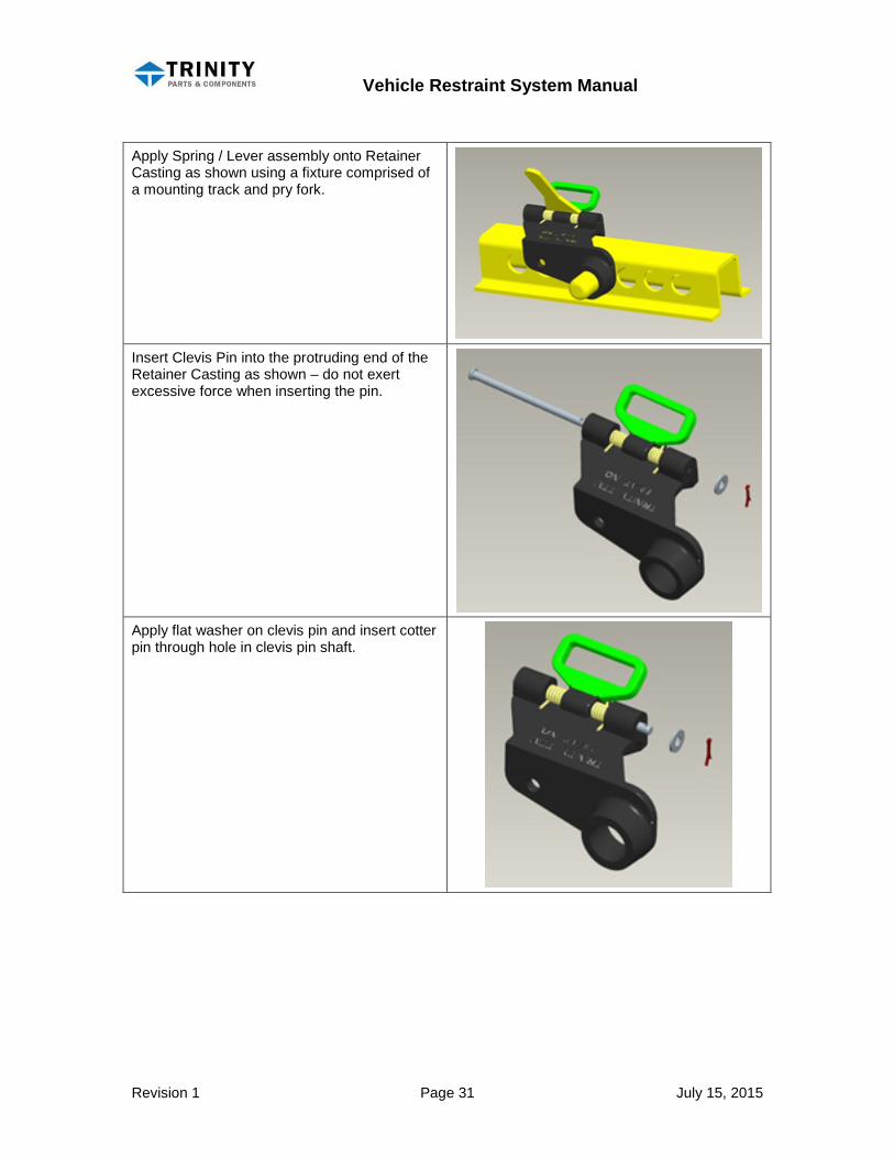
Apply Spring / Lever assembly onto Retainer Casting as shown using a fixture comprised of a mounting track and pry fork.
Insert Clevis Pin into the protruding end of the Retainer Casting as shown – do not exert excessive force when inserting the pin.
Apply flat washer on clevis pin and insert cotter pin through hole in clevis pin shaft.
Vehicle Restraint System Manual
Revision 1 Page 32 July 15, 2015
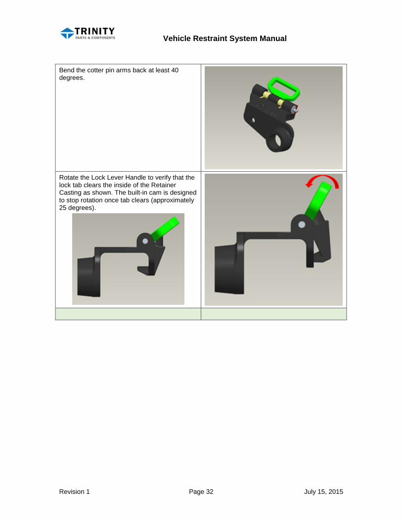
Bend the cotter pin arms back at least 40 degrees.
Rotate the Lock Lever Handle to verify that the lock tab clears the inside of the Retainer Casting as shown. The built-in cam is designed to stop rotation once tab clears (approximately 25 degrees).

Vehicle Restraint System Manual
Revision 1 Page 33 July 15, 2015
Assemble Anchor Mandrel and Retainer Casting
Apply first stainless steel Washer to Mandrel.
Insert composite Bushing into Retainer Casting. Bushing is saturated with mineral oil to aid with insertion.
Insert Retainer with Bushing onto Mandrel.
Vehicle Restraint System Manual
Revision 1 Page 34 July 15, 2015
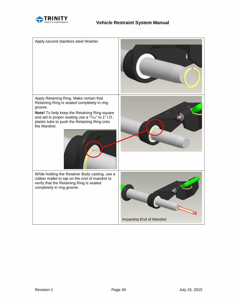
Apply second stainless steel Washer.
Apply Retaining Ring. Make certain that Retaining Ring is seated completely in ring groove. Note! To help keep the Retaining Ring square and aid in proper seating use a 15/16” to 1” I.D. plastic tube to push the Retaining Ring onto the Mandrel.
While holding the Retainer Body casting, use a rubber mallet to tap on the end of mandrel to verify that the Retaining Ring is seated completely in ring groove.
Impacting End of Mandrel
Vehicle Restraint System Manual
Revision 1 Page 35 July 15, 2015
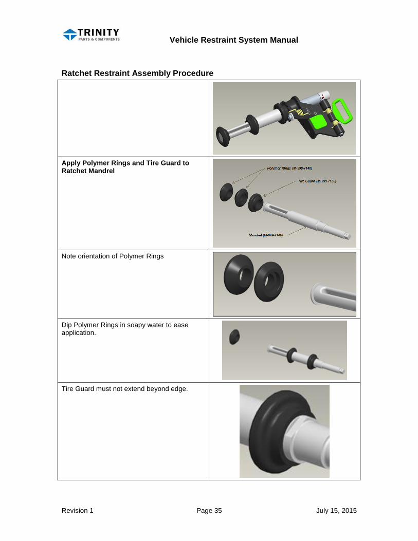
Ratchet Restraint Assembly Procedure
Apply Polymer Rings and Tire Guard to Ratchet Mandrel
Note orientation of Polymer Rings
Dip Polymer Rings in soapy water to ease application.
Tire Guard must not extend beyond edge.
Vehicle Restraint System Manual
Revision 1 Page 36 July 15, 2015
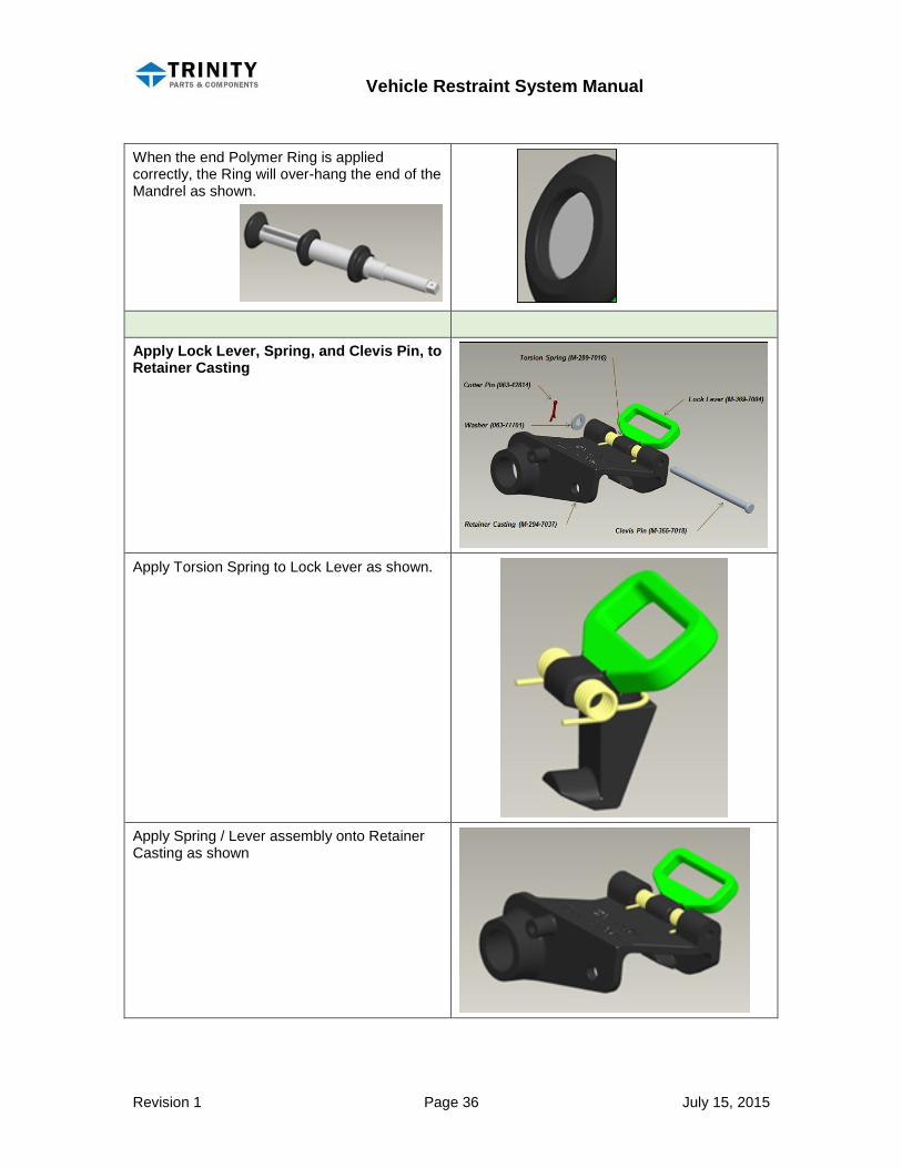
When the end Polymer Ring is applied correctly, the Ring will over-hang the end of the Mandrel as shown.
Apply Lock Lever, Spring, and Clevis Pin, to Retainer Casting
Apply Torsion Spring to Lock Lever as shown.
Apply Spring / Lever assembly onto Retainer Casting as shown
Vehicle Restraint System Manual
Revision 1 Page 37 July 15, 2015
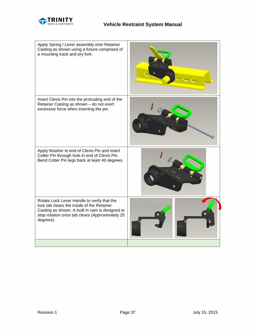
Apply Spring / Lever assembly onto Retainer Casting as shown using a fixture comprised of a mounting track and pry fork.
Insert Clevis Pin into the protruding end of the Retainer Casting as shown – do not exert excessive force when inserting the pin.
Apply Washer to end of Clevis Pin and insert Cotter Pin through hole in end of Clevis Pin. Bend Cotter Pin legs back at least 40 degrees.
Rotate Lock Lever Handle to verify that the lock tab clears the inside of the Retainer Casting as shown. A built in cam is designed to stop rotation once tab clears (Approximately 25 degrees).
Vehicle Restraint System Manual
Revision 1 Page 38 July 15, 2015
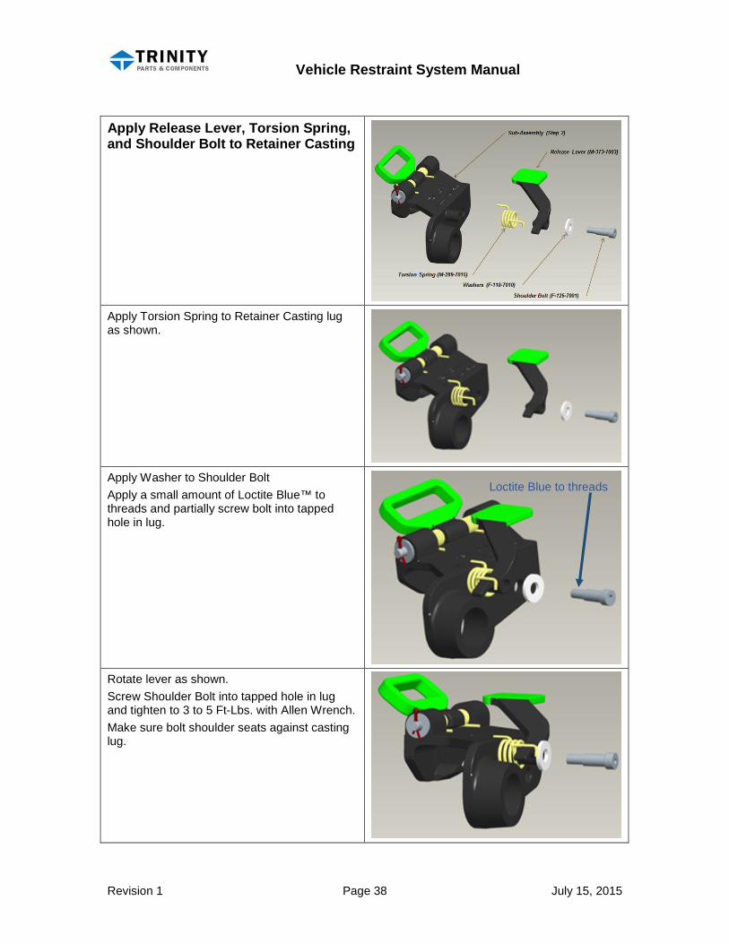
Apply Release Lever, Torsion Spring, and Shoulder Bolt to Retainer Casting
Apply Torsion Spring to Retainer Casting lug as shown.
Apply Washer to Shoulder Bolt Apply a small amount of Loctite Blue™ to threads and partially screw bolt into tapped hole in lug.
Rotate lever as shown. Screw Shoulder Bolt into tapped hole in lug and tighten to 3 to 5 Ft-Lbs. with Allen Wrench. Make sure bolt shoulder seats against casting lug.
Loctite Blue to threads

Vehicle Restraint System Manual
Revision 1 Page 39 July 15, 2015
Note: Lever will be under slight load during final tightening of Shoulder Bolt. Make sure spring wire is not sandwiched between Lug face and Lever.
Assemble Ratchet Mandrel, Retainer Casting, Ratchet, and End Cap Assemble Ratchet Mandrel sub-assembly Retainer Casting sub-assembly Ratchet Bushing Washers End Cap and Roll Pin. Apply Ratchet on the Mandrel and align the flat segment of the Ratchet with the flat recess on the Mandrel. Note Ratchet tooth orientation.

Vehicle Restraint System Manual
Revision 1 Page 40 July 15, 2015
Apply stainless steel Washer F-118-7009 on to Mandrel.
Insert composite Bushing into Retainer Casting. Bushing is saturated with mineral oil to aid with insertion.
Insert Retainer Casting (with inserted Bushing) onto Mandrel. Note: Ratchet Release Lever will have to be rotated from its rest position to clear Ratchet. Release Lever will engage Ratchet teeth when assembly is fully engaged.
Apply Washer (F-118-7011).
Apply Journal Bearings (2 pieces)
Vehicle Restraint System Manual
Revision 1 Page 41 July 15, 2015
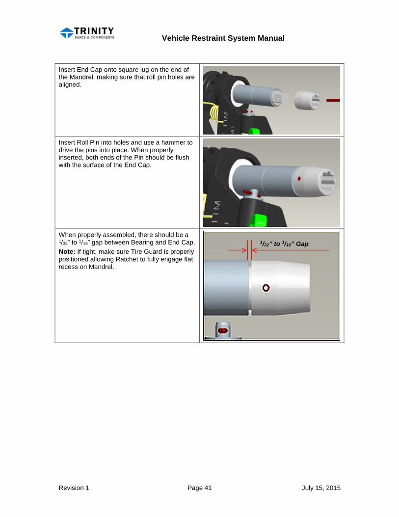
Insert End Cap onto square lug on the end of the Mandrel, making sure that roll pin holes are aligned.
Insert Roll Pin into holes and use a hammer to drive the pins into place. When properly inserted, both ends of the Pin should be flush with the surface of the End Cap.
When properly assembled, there should be a 1/32” to 1/16” gap between Bearing and End Cap. Note: If tight, make sure Tire Guard is properly positioned allowing Ratchet to fully engage flat recess on Mandrel.
1/32” to 1/16” Gap
Vehicle Restraint System Manual
Revision 1 Page 42 July 15, 2015
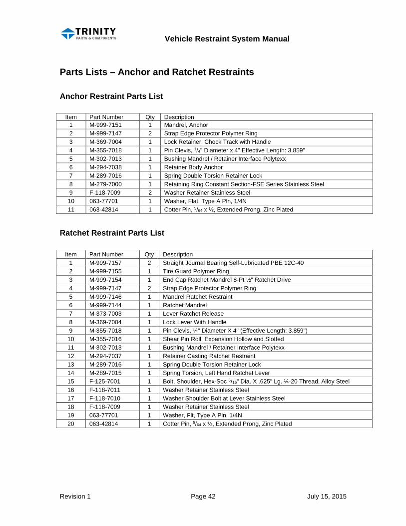
Parts Lists – Anchor and Ratchet Restraints
Anchor Restraint Parts List
Item Part Number Qty Description 1 M-999-7151 1 Mandrel, Anchor 2 M-999-7147 2 Strap Edge Protector Polymer Ring 3 M-369-7004 1 Lock Retainer, Chock Track with Handle 4 M-355-7018 1 Pin Clevis, 1/4" Diameter x 4" Effective Length: 3.859" 5 M-302-7013 1 Bushing Mandrel / Retainer Interface Polytexx 6 M-294-7038 1 Retainer Body Anchor 7 M-289-7016 1 Spring Double Torsion Retainer Lock 8 M-279-7000 1 Retaining Ring Constant Section-FSE Series Stainless Steel 9 F-118-7009 2 Washer Retainer Stainless Steel 10 063-77701 1 Washer, Flat, Type A Pln, 1/4N 11 063-42814 1 Cotter Pin, 5/64 x ½, Extended Prong, Zinc Plated
Ratchet Restraint Parts List
Item Part Number Qty Description 1 M-999-7157 2 Straight Journal Bearing Self-Lubricated PBE 12C-40 2 M-999-7155 1 Tire Guard Polymer Ring 3 M-999-7154 1 End Cap Ratchet Mandrel 8-Pt ½" Ratchet Drive 4 M-999-7147 2 Strap Edge Protector Polymer Ring 5 M-999-7146 1 Mandrel Ratchet Restraint 6 M-999-7144 1 Ratchet Mandrel 7 M-373-7003 1 Lever Ratchet Release 8 M-369-7004 1 Lock Lever With Handle 9 M-355-7018 1 Pin Clevis, ¼" Diameter X 4" (Effective Length: 3.859")
10 M-355-7016 1 Shear Pin Roll, Expansion Hollow and Slotted 11 M-302-7013 1 Bushing Mandrel / Retainer Interface Polytexx 12 M-294-7037 1 Retainer Casting Ratchet Restraint 13 M-289-7016 1 Spring Double Torsion Retainer Lock 14 M-289-7015 1 Spring Torsion, Left Hand Ratchet Lever 15 F-125-7001 1 Bolt, Shoulder, Hex-Soc 5/16" Dia. X .625" Lg. ¼-20 Thread, Alloy Steel 16 F-118-7011 1 Washer Retainer Stainless Steel 17 F-118-7010 1 Washer Shoulder Bolt at Lever Stainless Steel 18 F-118-7009 1 Washer Retainer Stainless Steel 19 063-77701 1 Washer, Flt, Type A Pln, 1/4N 20 063-42814 1 Cotter Pin, 5/64 x ½, Extended Prong, Zinc Plated
Vehicle Restraint System Manual
Revision 1 Page 43 July 15, 2015
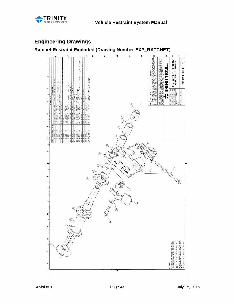
Engineering Drawings Ratchet Restraint Exploded (Drawing Number EXP_RATCHET)
Vehicle Restraint System Manual
Revision 1 Page 44 July 15, 2015
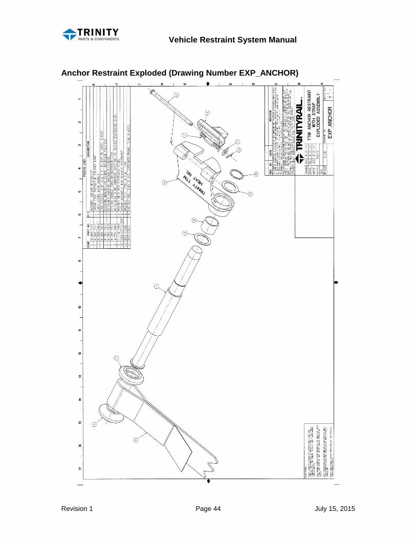
Anchor Restraint Exploded (Drawing Number EXP_ANCHOR)
Vehicle Restraint System Manual
Revision 1 Page 45 July 15, 2015
Restraints & Strap Assembly (Drawing Number M-099-7083)

Vehicle Restraint System Manual
Revision 1 Page 46 July 15, 2015
Service, Parts, and Rebuilding
Trinity Parts & Components, LLC 2548 N. E. 28th Street Fort Worth, TX 76111
Call (800) 336-7305 for Replacement Parts and
Rebuild Shipping instructions. www.trinityparts.com