VEHICLE RECOVERY ELECTRIC WINCH USE ...VEHICLE RECOVERY ELECTRIC WINCH USE & INSTALLATION...
16
Transcript of VEHICLE RECOVERY ELECTRIC WINCH USE ...VEHICLE RECOVERY ELECTRIC WINCH USE & INSTALLATION...
VEHICLE RECOVERY ELECTRIC WINCH USE & INSTALLATION INSTRUCTIONS
3
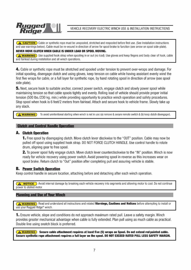
Installation requires purchase of a four-point mounting plate or properly equipped bumper unique to your vehicle.Dimensional footprint of your Rugged Ridge® winch is included with parts list at back of these instructions. Verify that the strength of the fasteners, mounting plate and vehicle frame attachment exceeds maximum rated pull of winch. Consult your retail distributor for available mounting plates and bumper options.
1. Align winch so that it sits flush and square on chosen mounting plate. Secure winch to mounting plateusing 3/8” x 1-1/4” fasteners and fender washers supplied.You may find it convenient at this time to feed the cable lead through the roller fairlead hole before you secure your winch plate/bumper. Note: Depending on your bumper, you may want to install your roller fairlead before you secure your winch. This will allow easy access to the roller fairlead back bolt.
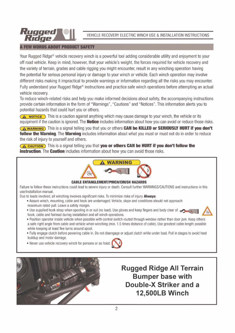
Winch must be used with Fairlead to avoid damage to cable, spool and gears. Mount fairlead using supplied fastenersand assure it is centered over spool so cable will wind tightly and evenly in direction of arrow ONLY (see arrow on spool side-plate).
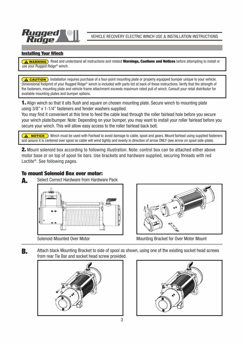
2. Mount solenoid box according to following illustration. Note: control box can be attached either abovemotor base or on top of spool tie bars. Use brackets and hardware supplied, securing threads with redLoctite®. See following pages.
CAUTION
To mount Solenoid Box over motor:Select Correct Hardware from Hardware PackA.
Attach black Mounting Bracket to side of spool as shown, using one of the existing socket head screws from rear Tie Bar and socket head screw provided.
B.
Solenoid Mounted Over Motor Mounting Bracket for Over Motor Mount
NOTICE
Installing Your Winch
WARNING Read and understand all instructions and related Warnings, Cautions and Notices before attempting to install or use your Rugged Ridge® winch.
VEHICLE RECOVERY ELECTRIC WINCH USE & INSTALLATION INSTRUCTIONS
4
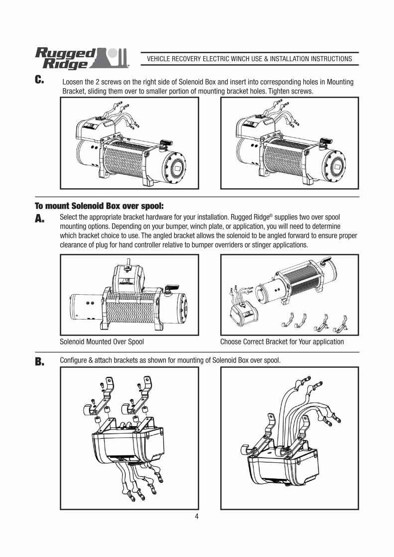
Loosen the 2 screws on the right side of Solenoid Box and insert into corresponding holes in Mounting Bracket, sliding them over to smaller portion of mounting bracket holes. Tighten screws.
C.
A.To mount Solenoid Box over spool:
Select the appropriate bracket hardware for your installation. Rugged Ridge® supplies two over spoolmounting options. Depending on your bumper, winch plate, or application, you will need to determinewhich bracket choice to use. The angled bracket allows the solenoid to be angled forward to ensure properclearance of plug for hand controller relative to bumper overriders or stinger applications.
Configure & attach brackets as shown for mounting of Solenoid Box over spool.B.
Solenoid Mounted Over Spool Choose Correct Bracket for Your application
VEHICLE RECOVERY ELECTRIC WINCH USE & INSTALLATION INSTRUCTIONS
5
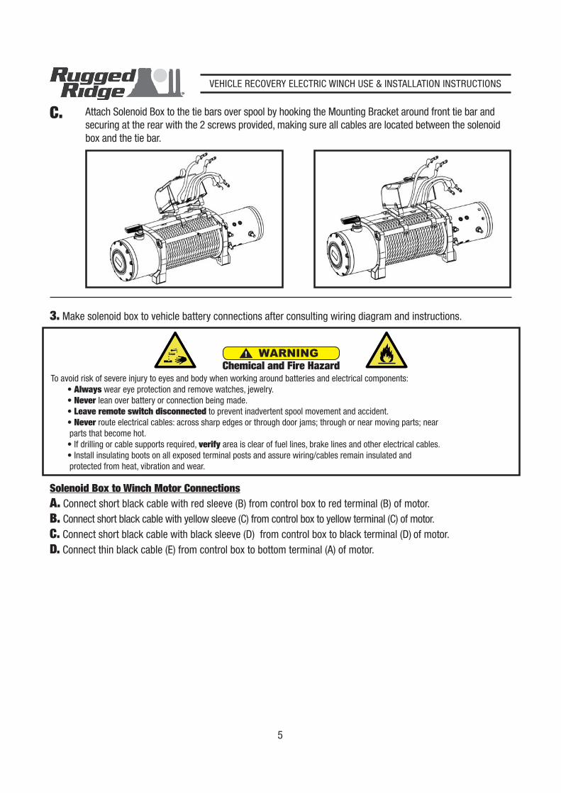
Attach Solenoid Box to the tie bars over spool by hooking the Mounting Bracket around front tie bar andsecuring at the rear with the 2 screws provided, making sure all cables are located between the solenoidbox and the tie bar.
C.
To avoid risk of severe injury to eyes and body when working around batteries and electrical components:Always wear eye protection and remove watches, jewelry.Never lean over battery or connection being made.Leave remote switch disconnected to prevent inadvertent spool movement and accident.Never route electrical cables: across sharp edges or through door jams; through or near moving parts; near
parts that become hot., verify area is clear of fuel lines, brake lines and other electrical cables.
ating boots on all exposed terminal posts and assure wiring/cables remain insulated and protected from heat, vibration and wear.
WARNINGChemical and Fire Hazard
3. Make solenoid box to vehicle battery connections after consulting wiring diagram and instructions.
Solenoid Box to Winch Motor ConnectionsA. Connect short black cable with red sleeve (B) from control box to red terminal (B) of motor.B. Connect short black cable with yellow sleeve (C) from control box to yellow terminal (C) of motor.C. Connect short black cable with black sleeve (D) from control box to black terminal (D) of motor.D. Connect thin black cable (E) from control box to bottom terminal (A) of motor.
VEHICLE RECOVERY ELECTRIC WINCH USE & INSTALLATION INSTRUCTIONS
6
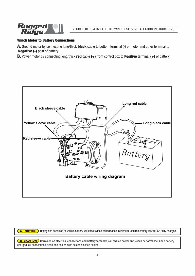
A. Ground motor by connecting long/thick black cable to bottom terminal (-) of motor and other terminal to Negative (-) post of battery.B. Power motor by connecting long/thick red cable (+) from control box to Positive terminal (+) of battery.
CAUTION
Winch Motor to Battery Connections
NOTICE
Corrosion on electrical connections and battery terminals will reduce power and winch performance. Keep batterycharged, all connections clean and sealed with silicone-based sealer.
Rating and condition of vehicle battery will affect winch performance. Minimum required battery is 650 CCA, fully charged.
VEHICLE RECOVERY ELECTRIC WINCH USE & INSTALLATION INSTRUCTIONS
10
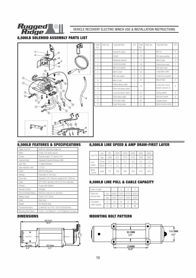
8,500LB SOLENOID ASSEMBLY PARTS LIST
8,500LB FEATURES & SPECIFICATIONSRated Line Pull 8500LB (3852kg) Single-line
Motor 5.5hp 12V Series wound
Control Remote switch, 12” lead (3.7m)
Solenoid style Integrated Solenoid Module (ISM)
Gear Train 3-Stage Planetary
Gear reduction ratio 172.8:1
Clutch Shift Pin Ring Gear
Braking Automatic In-The-Drum
Drum size Diameter 2.52” (64mm) Length 8.82” (224mm)
Cable 94”21/64” diameter (28.5m,8.2mm diameter)
Fairlead 4-way roller fairlead
Remote Control Included
Recommended Battery 650CCA minimum for winching
Battery Leads 25mm 72”(1.83m)
Finish Dark Gray
Weight 80.5lbs(36.5kg)
Overall dimensions (LxWxH)22”x6.3”x8.1”(557x160x205mm)
Mounting Bolt Pattern 10.00 +/- 0.015Nx4.50 +/- 0.0101N(254x114.3mm)
MOUNTING BOLT PATTERN
8,500LB LINE SPEED & AMP DRAW-FIRST LAYER
Line PullLbs NO 2000 4000 6000 8000 8500
Kgs LOAD 910 1814 2720 3630 3850
Line
speed
Ft/min 37.2 18 13.1 10.2 8.2 7.2
M/min 11.4 5.5 4 3.1 2.5 2.2
Motor
Currentamps 70 190 260 335 410 425
8,500LB LINE PULL & CABLE CAPACITY
Layer of cable 1 2 3 4
Rated line
pull per layer
Lbs 8500 7432 6730 6245
Kgs 3850 3370 3050 2830
Cumulative
cable capacity
Ft 16 42 72 94
m 5 12 21 28
DIMENSIONS
ITEM
NO.
PART NO. DESCRIPTION QTY ITEM
NO .
PART NO. DESCRIPTION QTY
1 Socket fix screw 2
20 1
2 Socket 1
21 1
3 Integrated solenoid 1
23
4
4 Control box plate 1
22
Control box mount
bracket (solution 2)2
5 M8 Lock washer 2
24
Control box bracket
8
6 M8X12 Bolt 4
25
Long black cable
4
7 M5 Lock washer 2
26
M5x20 Bolt
1
8 M6x10 bolt 3
27
Spring washer
1
9 Yellow sleeve cable 1
Alluminum washer
10 Short red sleeve cable 1
Angeled bracket
11 Long red sleeve cable 1
Hand remote control
12 Short black cable 1
13 Thin black cable 1
14 Cable fixing plate 1
15 M8 nut 4
16 M3 spring washer 2
17 M5X12 Bolt 10
18 Control box cover 1
19 Anti-dust cover 1
VEHICLE RECOVERY ELECTRIC WINCH USE & INSTALLATION INSTRUCTIONS
11
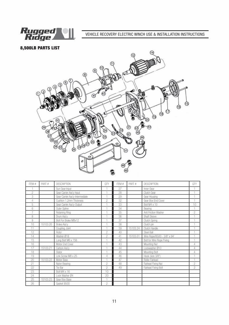
8,500LB PARTS LIST
ITEM # PART # DESCRIPTION QTY ITEM # PART # DESCRIPTION QTY
1 Sun Gear-Input 1 27 Inner Gear 1
2 Gear Carrier Ass’y Input 1 28 Clutch Gear 1
3 Gear Carrier Ass’y-Intermediate 1 29 Gear Housing 1
4 Cushion 1.2mm Thickness 2 32 Gear Box End Cover 1
5 Gear Carrier Ass’y-Output 1 33 Bolt M4 x 10 10
6 Outer Spline 1 34 Bearing 1
7 Retaining Ring 1 35 Anti Friction Washer 2
8 Drum Ass’y 1 36 Shaft Sleeve 1
9 Bolt For Brake M8x12 1 37 Clutch Spring 1
10 15103.20 Brake Ass’y 1 38 Clutch pin 1
11 Coupling Joint 1 39 15103.24 Clutch Handle 1
12 Rotor 2 40 Steel Ball 1
14 Washer Ø18 2 41 15103.01 Wire Rope/8500 - 3/8” x 94’ 1
15 Long Bolt M6 x 156 1 42 Bolt for Wire Rope Fixing 1
16 Motor End Cover 1 43 Mounting Nut 4
17 15103.21 Carbon Ass’y 1 44 Lockwasher Ø10 4
18 Stator 1 45 Mounting Bolt 4
19 Link Screw M8 x 25 4 46 Hook (size 3/8”) 1
20 15103.22 Motor Base 1 47 Roller Fairlead 1
21 Nylon Bearing 2 48 Fairlead Fixing Nut 2
22 Tie Bar 2 49 Fairlead Fixing Bolt 2
23 Bolt M4 x 16 10
24 Lock Washer Ø4 20
25 15103.23 Gear Box Base 1
26 Gasket 9500 2
VEHICLE RECOVERY ELECTRIC WINCH USE & INSTALLATION INSTRUCTIONS
12
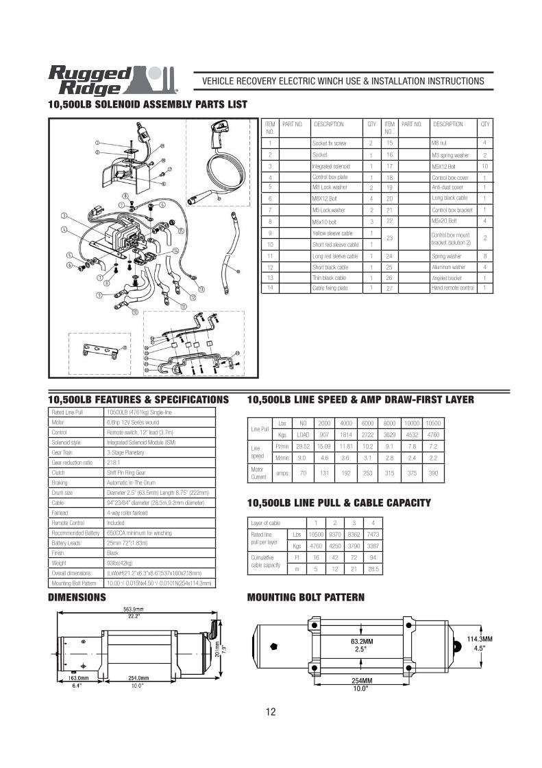
10,500LB SOLENOID ASSEMBLY PARTS LIST
10,500LB FEATURES & SPECIFICATIONSRated Line Pull 10500LB (4761kg) Single-line
Motor 6.6hp 12V Series wound
Control Remote switch, 12” lead (3.7m)
Solenoid style Integrated Solenoid Module (ISM)
Gear Train 3-Stage Planetary
Gear reduction ratio 218:1
Clutch Shift Pin Ring Gear
Braking Automatic In-The-Drum
Drum size Diameter 2.5” (63.5mm) Length 8.75” (222mm)
Cable 94”23/64” diameter (28.5m,9.2mm diameter)
Fairlead 4-way roller fairlead
Remote Control Included
Recommended Battery 650CCA minimum for winching
Battery Leads 25mm 72”(1.83m)
Finish Black
Weight 93lbs(42kg)
Overall dimensions (LxWxH)21.2”x6.3”x8.6”(537x160x218mm)
Mounting Bolt Pattern 10.00 +/- 0.015Nx4.50 +/- 0.0101N(254x114.3mm)
MOUNTING BOLT PATTERN
10,500LB LINE SPEED & AMP DRAW-FIRST LAYER
Line PullLbs NO 2000 4000 6000 8000 10000
Kgs LOAD 907 1814 2722 3629 4532
Line
speed
Ft/min 29.52 15.09 11.81 10.2 9.1 7.8
M/min 9.0 4.6 3.6 3.1 2.8 2.4
Motor
Currentamps 70 131 192 253 315 375
10500
4760
7.2
2.2
390
10,500LB LINE PULL & CABLE CAPACITY
Layer of cable 1 2 3 4
Rated line
pull per layer
Lbs 10500 9370 8362 7473
Kgs 4760 4250 3790 3387
Cumulative
cable capacity
Ft 16 42 72 94
m 5 12 21 28.5
DIMENSIONS
ITEM
NO.
PART NO. DESCRIPTION QTY ITEM
NO .
PART NO. DESCRIPTION QTY
1 Socket fix screw 2
20 1
2 Socket 1
21 1
3 Integrated solenoid 1
23
4
4 Control box plate 1
22
Control box mount
bracket (solution 2)2
5 M8 Lock washer 2
24
Control box bracket
8
6 M8X12 Bolt 4
25
Long black cable
4
7 M5 Lock washer 2
26
M5x20 Bolt
1
8 M6x10 bolt 3
27
Spring washer
1
9 Yellow sleeve cable 1
Alluminum washer
10 Short red sleeve cable 1
Angeled bracket
11 Long red sleeve cable 1
Hand remote control
12 Short black cable 1
13 Thin black cable 1
14 Cable fixing plate 1
15 M8 nut 4
16 M3 spring washer 2
17 M5X12 Bolt 10
18 Control box cover 1
19 Anti-dust cover 1
VEHICLE RECOVERY ELECTRIC WINCH USE & INSTALLATION INSTRUCTIONS
13
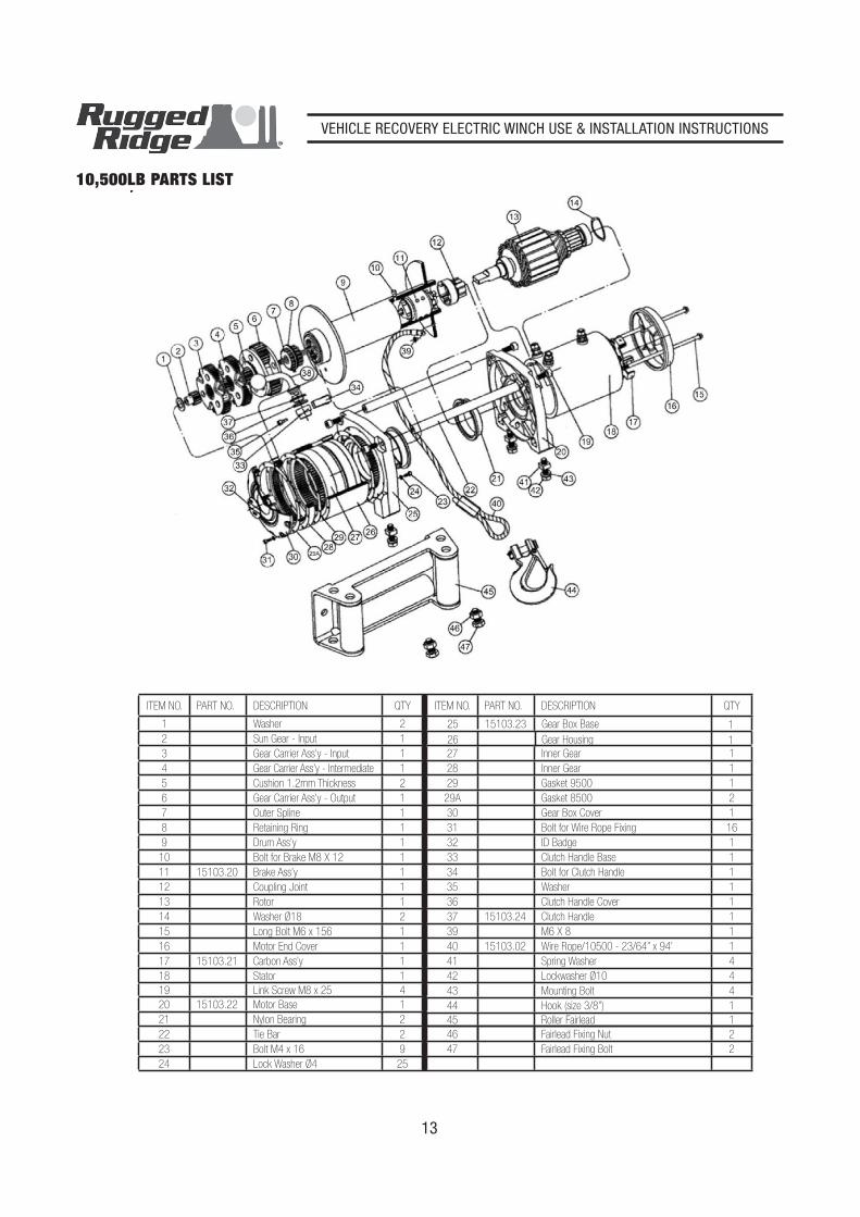
ITEM NO. PART NO. DESCRIPTION QTY ITEM NO. PART NO. DESCRIPTION QTY
1 Washer 2
27 Inner Gear 1
2 Sun Gear - Input 1
28 Inner Gear 1
3 Gear Carrier Ass’y - Input 1
29 Gasket 9500 1
4 Gear Carrier Ass’y - Intermediate 1
29A Gasket 8500 2
5 Cushion 1.2mm Thickness 2
30 Gear Box Cover 1
6 Gear Carrier Ass’y - Output 1
31 Bolt for Wire Rope Fixing 16
7 Outer Spline 1
32 ID Badge 1
8 Retaining Ring 1
33 Clutch Handle Base 1
9 Drum Ass’y 1
34 Bolt for Clutch Handle 1
10 Bolt for Brake M8 X 12 1
35 Washer 1
11 15103.20 Brake Ass’y 1
36 Clutch Handle Cover 1
12 Coupling Joint 1
37 15103.24 Clutch Handle 1
13 Rotor 1
39 M6 X 8 1
14 Washer Ø18 2
40 15103.02 Wire Rope/10500 - 23/64” x 94’ 1
15 Long Bolt M6 x 156 1
41 Spring Washer 4
16 Motor End Cover 1
42 Lockwasher Ø10 4
17 15103.21 Carbon Ass’y 1
43 Mounting Bolt 4
18 Stator 1
44 Hook (size 3/8”) 1
19 Link Screw M8 x 25 4
45 Roller Fairlead 1
20 15103.22 Motor Base 1
46 Fairlead Fixing Nut 2
21 Nylon Bearing 2
47 Fairlead Fixing Bolt 2
22 Tie Bar 2
23 Bolt M4 x 16 9
24 Lock Washer Ø4 25
25 15103.23 Gear Box Base 1
26 Gear Housing 1
10,500LB PARTS LIST
VEHICLE RECOVERY ELECTRIC WINCH USE & INSTALLATION INSTRUCTIONS
14
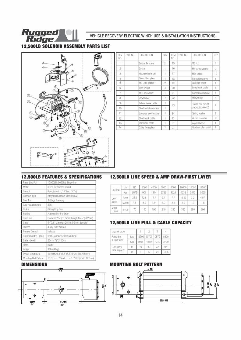
12,500LB SOLENOID ASSEMBLY PARTS LIST
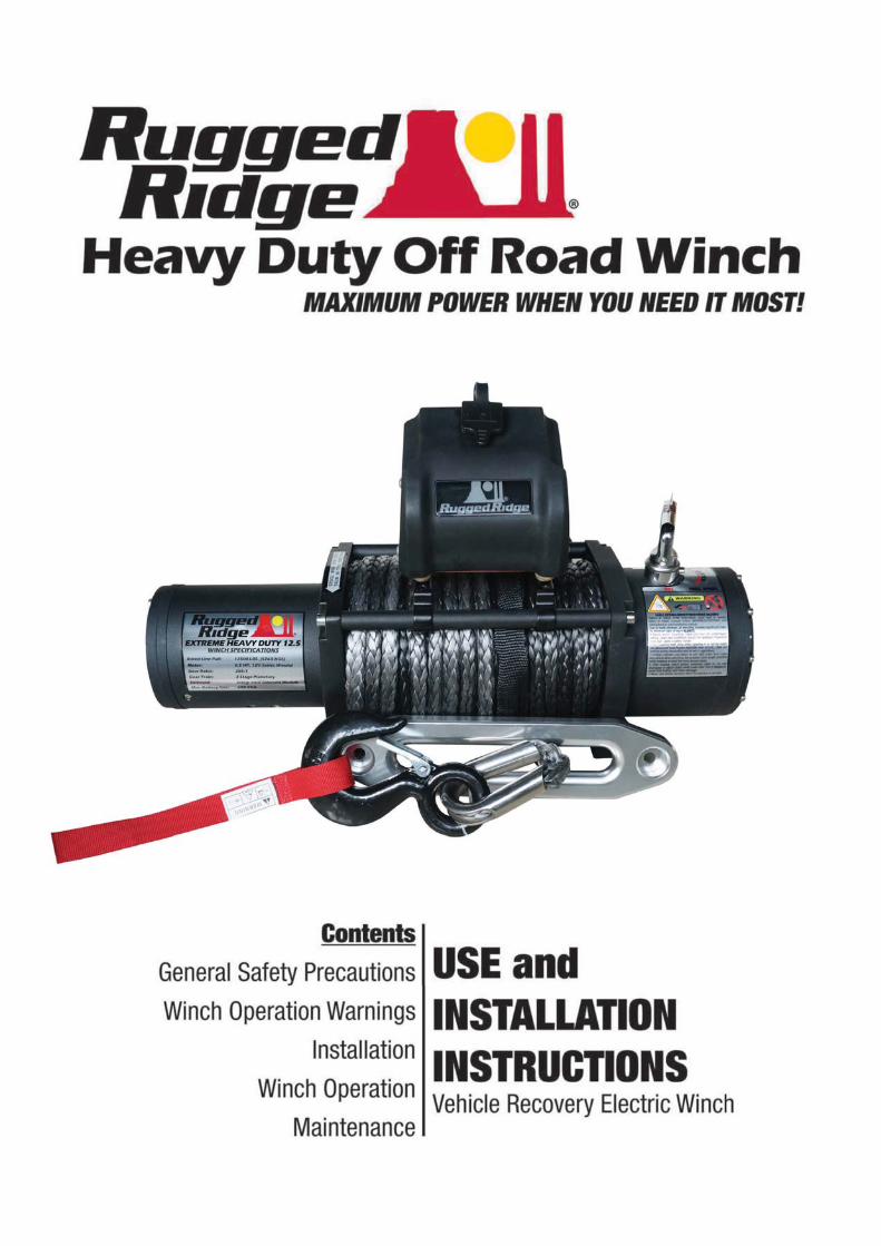
12,500LB FEATURES & SPECIFICATIONSRated Line Pull 12500LB (5665kg) Single-line
Motor 6.6hp 12V Series wound
Control Remote switch, 12” lead (3.7m)
Solenoid style Integrated Solenoid Module (ISM)
Gear Train 3-Stage Planetary
Gear reduction ratio 265:1
Clutch Sliding Ring Gear
Braking Automatic In-The-Drum
Drum size Diameter 2.5” (63.5mm) Length 8.75” (222mm)
Cable 94”3/8” diameter (28.5m,9.5mm diameter)
Fairlead 4-way roller fairlead
Remote Control Included
Recommended Battery 650CCA minimum for winching
Battery Leads 25mm 72”(1.83m)
Finish Black
Weight 93lbs(42kg)
Overall dimensions (LxWxH)21.3”x6.3”x8.6”(542x160x218mm)
Mounting Bolt Pattern 10.00 +/- 0.015Nx4.50 +/- 0.0101N(254x114.3mm)
MOUNTING BOLT PATTERN
12,500LB LINE SPEED & AMP DRAW-FIRST LAYER
Line PullLbs NO 2000 4000 6000 8000 10000
Kgs LOAD 907 1814 2722 3629 4532
Line
speed
Ft/min 24.5 12.8 11.7 9.7 7.7 6.53
M/min 7.5 3.9 3.6 3.0 2.4 2.0
Motor
Currentamps 70 140 190 240 290 335
12000
5440
7.2
1.7
380
12500
5665
4.57
1.5
390
12,500LB LINE PULL & CABLE CAPACITY
Layer of cable 1 2 3 4
Rated line
pull per layer
Lbs 12500 10700 9575 8800
Kgs 5665 4850 4340 3790
Cumulative
cable capacity
Ft 16 42 72 94
m 5 12 21 28.5
DIMENSIONS
ITEM
NO.
PART NO. DESCRIPTION QTY ITEM
NO .
PART NO. DESCRIPTION QTY
1 Socket fix screw 2
20 1
2 Socket 1
21 1
3 Integrated solenoid 1
23
4
4 Control box plate 1
22
Control box mount
bracket (solution 2)2
5 M8 Lock washer 2
24
Control box bracket
8
6 M8X12 Bolt 4
25
Long black cable
4
7 M5 Lock washer 2
26
M5x20 Bolt
1
8 M6x10 bolt 3
27
Spring washer
1
9 Yellow sleeve cable 1
Alluminum washer
10 Short red sleeve cable 1
Angeled bracket
11 Long red sleeve cable 1
Hand remote control
12 Short black cable 1
13 Thin black cable 1
14 Cable fixing plate 1
15 M8 nut 4
16 M3 spring washer 2
17 M5X12 Bolt 10
18 Control box cover 1
19 Anti-dust cover 1

VEHICLE RECOVERY ELECTRIC WINCH USE & INSTALLATION INSTRUCTIONS
15
ITEM NO. PART NO. DESCRIPTION QTY ITEM NO. PART NO. DESCRIPTION QTY
1 Washer 2
27 Inner Gear 1
2 Sun Gear - Input 1
28 Inner Gear 1
3 Gear Carrier Ass’y - Input 1
29 Gasket 9500 1
4 Gear Carrier Ass’y - Intermediate 1
29A Gasket 8500 2
5 Cushion 1.2mm Thickness 2
30 Gear Box Cover 1
6 Gear Carrier Ass’y - Output 1
31 Bolt for Wire Rope Fixing 16
7 Outer Spline 1
32 ID Badge 1
8 Retaining Ring 1
33 Clutch Handle Base 1
9 Drum Ass’y 1
34 Bolt for Clutch Handle 1
10 Bolt for Brake M8 X 12 1
35 Washer 1
11 15103.20 Brake Ass’y 1
36 Clutch Handle Cover 1
12 Coupling Joint 1
37 15103.24 Clutch Handle 1
13 Rotor 1
39 M6 X 8 1
14 Washer Ø18 2
40 15103.03 Wire Rope/12500 - 3/8” x 94’ 1
15 Long Bolt M6 x 156 1
41 Spring Washer 4
16 Motor End Cover 1
42 Lockwasher Ø10 4
17 15103.21 Carbon Ass’y 1
43 Mounting Bolt 4
18 Stator 1
44 Hook (size 3/8”) 1
19 Link Screw M8 x 25 4
45 Roller Fairlead 1
20 15103.22 Motor Base 1
46 Fairlead Fixing Nut 2
21 Nylon Bearing 2
47 Fairlead Fixing Bolt 2
22 Tie Bar 2
23 Bolt M4 x 16 9
24 Lock Washer Ø4 25
25 15103.23 Gear Box Base 1
26 Gear Housing 1
12,500LB PARTS LIST