Vehicle frontal protection system geometry and pedestrian ...
18
Vehicle frontal protection system geometry and pedestrian impacts: the effect of AS 4876.1-2002 geometric criteria SD Doecke, RWG Anderson CASR REPORT SERIES CASR122 October 2014
Transcript of Vehicle frontal protection system geometry and pedestrian ...

Vehicle frontal protection system geometry and pedestrian impacts: the effect of AS 4876.1-2002 geometric criteria SD Doecke, RWG Anderson
CASR REPORT SERIES
CASR122
October 2014

© The University of Adelaide 2014 The views expressed in this report are those of the authors and do not necessarily represent those of the University of Adelaide or the funding organisations.
Report documentation
REPORT NO. DATE PAGES ISBN ISSN
CASR122 October 2014 18 978 1 921645 60 0 1449-2237
TITLE
Vehicle frontal protection system geometry and pedestrian impacts: the effect of AS 4876.1-2002 geometric criteria
AUTHORS
SD Doecke, RWG Anderson
PERFORMING ORGANISATION
Centre for Automotive Safety Research The University of Adelaide South Australia 5005 AUSTRALIA
SPONSORED BY
Department of Planning, Transport and Infrastructure GPO Box 1533 Adelaide SA 5001 AUSTRALIA
AVAILABLE FROM
Centre for Automotive Safety Research http://casr.adelaide.edu.au/publications/researchreports
ABSTRACT
Australian Standard AS 4876.1-2002 stipulates requirements for motor vehicle frontal protection systems (VFPS), colloquially known as bull bars. Section 2 of the Standard sets design and installation requirements and has a particular focus on the geometry of the VFPS, stipulating that their geometry should generally conform to the frontal shape of the vehicle. The aim of this project was to examine the differences between pedestrian impacts with vehicles fitted with a VFPS with geometry that meets the requirements of Section 2 of AS48761.1-2002 and VFPS that do not meet these requirements. MADYMO was used to simulate pedestrian impacts with vehicles that had VFPS fitted. The simulations showed that conforming VFPS tend to redistribute impact forces to contacts with the bumper section of the VFPS. For an SUV impact, the increase in risk of pelvic injury produced by this change in loading pattern is only marginally offset by a small reduction in the probability of upper leg injury. For a sedan impact, increased risk in upper leg injury may be offset by a reduction in risk to lower leg injury, depending on the material of the VFPS. Conforming VFPS also tended to result in lower head impact speeds with the vehicle, reducing the severity of the impact with the head, resulting in a reduction in risk of serious head injury well over 50% based on the change in the head injury criterion. The extent to which the results of the narrow set of impact conditions studied can be generalised to all collisions is not completely clear, although it seems reasonable to suggest that the effects will apply where the interaction with the bull bar and the pedestrian is at, or below, the pelvic region. It is less likely that the geometry of the bull bar would affect children to the same extent. The results of this brief simulation study support the expectation that the adoption of Section 2 of AS 4876.1-2002 will lead to reductions in injury risk to people struck by VFPS.
KEYWORDS
Vehicle frontal protection system, bull bar, pedestrian, injury

CASR Road Safety Research Report | Vehicle frontal protection system geometry and pedestrian impacts: the effect of AS 4876.1-2002 geometric criteria iii
Summary
Australian Standard AS 4876.1-2002 stipulates requirements for motor vehicle frontal protection systems (VFPS), colloquially known as bull bars. Section 2 of the Standard sets design and installation requirements and has a particular focus on the geometry of the VFPS, stipulating that “a VFPS shall have a profile that generally conforms to the shape, in plan view, front view and side view, of the front of the vehicle to which it is fitted” (Standards Australia, 2002). South Australia has recently adopted Section 2 of the Standard, specifying that new vehicles sold after the 1st of July 2013 may only be fitted with a VFPS that conforms to the requirements of Section 2. The aim of this project was to examine the differences between pedestrian impacts with vehicles fitted with a VFPS with geometry that meets the requirements of Section 2 of AS48761.1-2002 and VFPS that do not meet these requirements.
MADYMO was used to simulate pedestrian impacts with vehicles that had VFPS fitted. In the simulations, the VFPS were attached rigidly to either a Sports Utility Vehicle or a sedan vehicle model. The SUV vehicle model was based on a 2006 Nissan Patrol. The sedan vehicle model had geometry based on a Holden (General Motors) Commodore from 2006. To represent nonconforming VFPS in the simulations the position of the top bar on each of the VFPS was moved forward. Two such configurations were produced. The first nonconforming configuration was termed ‘in line’ because the top bar was positioned in line with the bar directly below it. The second nonconforming configuration was termed ‘forward’ as the top bar was positioned forward of the bar directly below it. The vehicle was set to have an initial speed of 40 km/h at impact between the standard VFPS configuration and the pedestrian. An acceleration of -0.75g was applied to the vehicle over the complete duration of the simulation to represent emergency braking.
VFPS geometry affects injury risk in these simulations through two main mechanisms. In the first case, conforming VFPS tend to redistribute impact forces to contacts with the bumper section of the VFPS. For an SUV impact, the increase in risk of pelvic injury produced by this change in loading pattern is only marginally offset by a small reduction in the probability of upper leg injury. For a sedan impact increased risk in upper leg injury may be offset by a reduction in risk to lower leg injury, depending on the material of the VFPS. In the second case, conforming bull bars tended to result in lower head impact speeds with the vehicle, reducing the severity of the impact with the head. In our simulations of SUV pedestrian impacts, the reduction in risk of serious head injury was well over 50% based on the change in the head injury criterion, commensurate with what might be expected based on the change in the head impact speed.
The relatively benign effects of conformity for sedan impacts should be viewed in light of research conducted by Doecke et al. (2008) that found that the vast majority of pedestrian exposure to VFPS came from SUVs, with only 12% attributed to sedans. VFPS regulation designed to protect pedestrians should therefore be weighted towards the SUV case.
The extent to which the results of the narrow set of impact conditions studied can be generalised to all collisions is not completely clear, although it seems reasonable to suggest that the effects will apply where the interaction with the bull bar and the pedestrian is at, or below, the pelvic region. It is less likely that the geometry of the bull bar would affect children to the same extent.
The results of this brief simulation study support the expectation that the adoption of Section 2 of AS 4876.1-2002 will lead to reductions in injury risk to people struck by VFPS.

CASR Road Safety Research Report | Vehicle frontal protection system geometry and pedestrian impacts: the effect of AS 4876.1-2002 geometric criteria iv
Contents
1 Introduction .......................................................................................................................................................................... 1 2 Method ................................................................................................................................................................................ 2 3 Results ................................................................................................................................................................................ 5 4 Limitations ......................................................................................................................................................................... 11 5 Discussion ......................................................................................................................................................................... 12 References ............................................................................................................................................................................... 14

CASR Road Safety Research Report | Vehicle frontal protection system geometry and pedestrian impacts: the effect of AS 4876.1-2002 geometric criteria 1
1 Introduction
Australian Standard AS 4876.1-2002 stipulates requirements for motor vehicle frontal protection systems (VFPS), colloquially known as bull bars. Section 2 of the Standard sets design and installation requirements and has a particular focus on the geometry of the VFPS, stipulating that “a VFPS shall have a profile that generally conforms to the shape, in plan view, front view and side view, of the front of the vehicle to which it is fitted” (Standards Australia, 2002). Some general profile requirements are shown pictorially in the standard and are displayed below (Figure 1.1).
Figure 1.1 General AS 4876.1-2002 profile requirements for VFPS (Standards Australia, 2002)
South Australia has recently adopted Section 2 of the Standard, specifying that new vehicles sold after the 1st of July 2013 may only be fitted with a VFPS that conforms to the requirements of Section 2. One of the reasons for the new requirements is that it is thought that poor geometry can cause the magnitude and pattern of loading on a pedestrian to change in undesirable ways: for example the forward projection of the top bar of the VFPS may concentrate the force of the collision on the body of the pedestrian during a collision, whereas a geometry that conforms more to the profile of the vehicle may lead to a more even distribution of forces.
The aim of this project was to examine the differences between pedestrian impacts with vehicles fitted with a VFPS with geometry that meets the requirements of Section 2 of AS48761.1-2002 and VFPS that do not meet these requirements.
AS 4876.1—2002
www.standards.com.au Standards Australia
9
FIGURE 2.3 GENERAL PROFILE REQUIREMENT FOR SEDAN TYPE VEHICLE—NUDGE BAR
FIGURE 2.4 GENERAL PROFILE REQUIREMENT FOR FOUR WHEEL DRIVE TYPEVEHICLE—BUMPER REPLACEMENT
Acce
ssed
by
UNIV
ERSI
TY O
F AD
ELAI
DE o
n 03
Jan
201
4 (D
ocum
ent c
urre
ncy
not g
uara
ntee
d wh
en p
rinte
d)
AS 4876.1—2002
Standards Australia www.standards.com.au
8
FIGURE 2.1 GENERAL PROFILE REQUIREMENT FOR SEDAN TYPE VEHICLE—REPLACEMENT BUMPER
FIGURE 2.2 GENERAL PROFILE REQUIREMENT FOR SEDAN TYPE VEHICLE—OVERBUMPER
Acce
ssed
by
UNIV
ERSI
TY O
F AD
ELAI
DE o
n 03
Jan
201
4 (D
ocum
ent c
urre
ncy
not g
uara
ntee
d wh
en p
rinte
d)

CASR Road Safety Research Report | Vehicle frontal protection system geometry and pedestrian impacts: the effect of AS 4876.1-2002 geometric criteria 2
2 Method MADYMO was used to simulate pedestrian impacts with vehicles that had a VFPS fitted. The human model that was used to represent the pedestrian was developed specifically to simulate pedestrians in car–pedestrian collisions. The model represented a 50th-percentile male (for weight and height) with segment lengths, masses, and moments of inertia generated from the Generator of Body Data (GEBOD) anthropometric database (Baughman 1983).
Results of validation studies performed with the model are described in Anderson et al. (2005). In summary, the motions of segments of the model fit kinematic corridors described in Ishikawa et al. (1993) and supplied by one of the authors of that study. The head–neck model subsystem has been designed according to moment corridors in saggital flexion/extension and lateral flexion measured by Thunnissen et al. (1995). Upon initial testing it was found that the shape of the pelvis and abdomen bodies was causing a high ‘clamping’ force to lock the body onto the top bar of the VFPS. To mitigate this the ellipsoid that represented the abdomen was elongated and the friction value associated with the abdomen and pelvis was reduced.
The vehicle and conforming VFPS models had been developed for previous simulations conducted by CASR staff (Anderson and Doecke, 2011; Anderson et al. 2009a) using measured geometry and stiffness’s derived from physical impact tests (Anderson et al. 2006). More information on the contact model used can be found in Anderson et al. (2009b). The VFPS that were modelled are shown in Figures 2.1 to 2.3. All of these VFPS conform to the standard and were designed to be fitted to a Nissan Patrol (2006 model).
Figure 2.1
Nissan Patrol alloy VFPS (Picture taken from Anderson et al. 2005 - letters correspond to impact test locations)
Figure 2.2
Nissan Patrol steel VFPS (Picture taken from Anderson et al. 2005 - letters correspond to impact test locations)
CASR Road Safety Research Report | Vehicle frontal protection system geometry and pedestrian impacts: the effect of AS 4876.1-2002 geometric criteria 3
Figure 2.3
Nissan Patrol polymer VFPS (Picture taken from Anderson et al. 2005 - letters correspond to impact test locations)
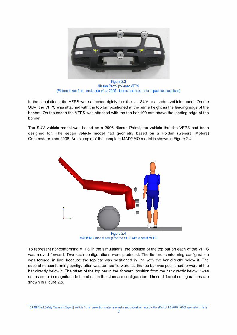
In the simulations, the VFPS were attached rigidly to either an SUV or a sedan vehicle model. On the SUV, the VFPS was attached with the top bar positioned at the same height as the leading edge of the bonnet. On the sedan the VFPS was attached with the top bar 100 mm above the leading edge of the bonnet.
The SUV vehicle model was based on a 2006 Nissan Patrol, the vehicle that the VFPS had been designed for. The sedan vehicle model had geometry based on a Holden (General Motors) Commodore from 2006. An example of the complete MADYMO model is shown in Figure 2.4.
Figure 2.4
MADYMO model setup for the SUV with a steel VFPS
To represent nonconforming VFPS in the simulations, the position of the top bar on each of the VFPS was moved forward. Two such configurations were produced. The first nonconforming configuration was termed ‘in line’ because the top bar was positioned in line with the bar directly below it. The second nonconforming configuration was termed ‘forward’ as the top bar was positioned forward of the bar directly below it. The offset of the top bar in the ‘forward’ position from the bar directly below it was set as equal in magnitude to the offset in the standard configuration. These different configurations are shown in Figure 2.5.

CASR Road Safety Research Report | Vehicle frontal protection system geometry and pedestrian impacts: the effect of AS 4876.1-2002 geometric criteria 4
Standard In line Forward
Figure 2.5
VFPS configurations
The vehicle was set to have an initial speed of 40 km/h at impact between the standard VFPS configuration and the pedestrian. An acceleration of -0.75g was applied to the vehicle over the complete duration of the simulation to represent emergency braking. A complete matrix of the simulations is shown in Table 2.1.
Table 2.1 Matrix of the simulations
Vehicle Material Geometry SUV Alloy Standard SUV Alloy In line SUV Alloy Forward SUV Polymer Standard SUV Polymer In line SUV Polymer Forward SUV Steel Standard SUV Steel In line SUV Steel Forward Sedan Alloy Standard Sedan Alloy In line Sedan Alloy Forward Sedan Polymer Standard Sedan Polymer In line Sedan Polymer Forward Sedan Steel Standard Sedan Steel In line Sedan Steel Forward

CASR Road Safety Research Report | Vehicle frontal protection system geometry and pedestrian impacts: the effect of AS 4876.1-2002 geometric criteria 5
3 Results
The difference in the position of the pedestrian relative to the SUV and steel VFPS at the time of the maximum trunk force and head impact are illustrated in Figure 3.1. As the top bar is moved forward the maximum trunk force occurs earlier, when only a small proportion of the impact load is being borne by the legs. The location of the head impact is moved forward as the top bar is moved forward: for the forward position this means the shoulder does little to cushion the head impact.
Standard
In line
Forward
Figure 3.1 Pedestrian positions at maximum trunk force time (left) and
head impact time (right) for an impact with an SUV with a steel VFPS

CASR Road Safety Research Report | Vehicle frontal protection system geometry and pedestrian impacts: the effect of AS 4876.1-2002 geometric criteria 6
The difference in the position of the pedestrian relative to the sedan and steel VFPS at the time of the maximum upper leg force and head impact are illustrated in Figure 3.2. In the forward position the upper leg takes the full the force of the impact. Like in Figure 3.1, the location of the head impact is moved forward as the top bar is moved forward.
Standard
In line
Forward
Figure 3.2 Pedestrian positions at maximum trunk force time (left) and
head impact time (right) for an impact with an sedan with a steel VFPS
The primary impact of the VFPS attached to the SUV is with the pedestrian’s upper leg and trunk. If the VFPS is attached to a sedan the primary impact is with the lower leg and upper leg. The differences in VFPS configurations change the distribution of the force of this primary impact. This is apparent in Figures 3.3 and 3.4. As the top bar of the VFPS is moved forward (in line and forward configurations) the impact force on the trunk increases but the force on the upper leg is reduced. This general pattern is observed in the results from both the polymer VFPS (Figure 3.3) and the steel VFPS

CASR Road Safety Research Report | Vehicle frontal protection system geometry and pedestrian impacts: the effect of AS 4876.1-2002 geometric criteria 7
(Figure 3.4) though the magnitude of change is quite different. The impact forces are, unsurprisingly, much higher for the steel VFPS.
The exact impact location of the top bar with the pedestrian will depend upon the height of this bar and the height of the pedestrian. In the simulations it appears to be striking either the top of the pelvis or just above the pelvis (see Figure 3.1). Song et al. (2005) reports fracture probabilities of 20% at 5250 N, 50% at 8,000 N and 80% at 10,800 N. Matsui et al. (2006) suggests pelvis fracture tolerance as 8,900 N. The values given by Song et al. imply that by moving the top bar forward the injury risk increases from about 20% to at least 50% for the polymer VFPS, though for the steel bar the injury risk is very high regardless of configuration. Given that the upper leg fracture tolerance (femur) has been generally reported to be, at most, around 10,000 N (Kress and Porta, 2001) it is unlikely that the reduction in impact force would result in a non-negligible reduction in fracture probability, even for the large reductions in impact force. Lower leg (tibia) fracture tolerances reported by Mo et al. (2012) average 2,300N, and ranged from about 1,300N to 3,900N. This suggests that moving the top bar of the VFPS forward could significantly increase the risk of lower leg fracture, especially in the forward configuration.
Figure 3.3 SUV polymer VFPS impact forces
Figure 3.4
SUV steel VFPS impact forces
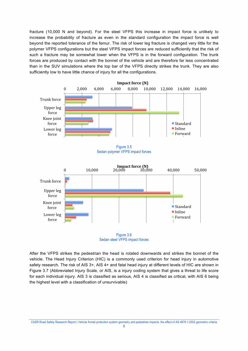
Figures 3.5 and 3.6 show that, for the VFPS fitted to the sedan model, moving the top bar forward to the in line and forward configurations produces a large increase in upper leg impact force and a reduction in the lower leg impact force. For the polymer VFPS this increase results in a change from an impact that is likely to produce upper leg fracture (8,000 N) to one that is almost certain to produce
0 2,000 4,000 6,000 8,000 10,000 12,000 14,000
Trunk force
Upper leg force
Knee joint force
Lower leg force
Impact force (N)
Standard Inline Forward
0 5,000 10,000 15,000 20,000 25,000 30,000 35,000 40,000 45,000 50,000
Trunk force
Upper leg force
Knee joint force
Lower leg force
Impact force (N)
Standard Inline Forward
CASR Road Safety Research Report | Vehicle frontal protection system geometry and pedestrian impacts: the effect of AS 4876.1-2002 geometric criteria 8
fracture (10,000 N and beyond). For the steel VFPS this increase in impact force is unlikely to increase the probability of fracture as even in the standard configuration the impact force is well beyond the reported tolerance of the femur. The risk of lower leg fracture is changed very little for the polymer VFPS configurations but the steel VFPS impact forces are reduced sufficiently that the risk of such a fracture may be somewhat lower when the VFPS is in the forward configuration. The trunk forces are produced by contact with the bonnet of the vehicle and are therefore far less concentrated than in the SUV simulations where the top bar of the VFPS directly strikes the trunk. They are also sufficiently low to have little chance of injury for all the configurations.
Figure 3.5 Sedan polymer VFPS impact forces
Figure 3.6 Sedan steel VFPS impact forces
After the VFPS strikes the pedestrian the head is rotated downwards and strikes the bonnet of the vehicle. The Head Injury Criterion (HIC) is a commonly used criterion for head injury in automotive safety research. The risk of AIS 3+, AIS 4+ and fatal head injury at different levels of HIC are shown in Figure 3.7 (Abbreviated Injury Scale, or AIS, is a injury coding system that gives a threat to life score for each individual injury. AIS 3 is classified as serious, AIS 4 is classified as critical, with AIS 6 being the highest level with a classification of unsurvivable)
0 2,000 4,000 6,000 8,000 10,000 12,000 14,000 16,000
Trunk force
Upper leg force
Knee joint force
Lower leg force
Impact force (N)
Standard Inline Forward
0 10,000 20,000 30,000 40,000 50,000
Trunk force
Upper leg force
Knee joint force
Lower leg force
Impact force (N)
Standard Inline Forward

CASR Road Safety Research Report | Vehicle frontal protection system geometry and pedestrian impacts: the effect of AS 4876.1-2002 geometric criteria 9
Figure 3.7
Head injury risk and HIC (National Highway Traffic Safety Administration, 1997)
The HIC values for each of the simulations that were determined within MADYMO are shown in Table 3.1. The sedan simulations produced low HIC values regardless of VFPS configuration or material that would not normally be of concern. However, many of the SUV simulations produced HIC values that correlate with a high risk of injury. The non-conforming VFPS configurations on SUVs (in line and forward) consistently produced substantially higher HIC values that for the conforming (standard) configuration.
Table 3.1 HIC from MADYMO simulations by vehicle, VFPS model and configuration
Vehicle model
VFPS model
Configuration
Standard In line Forward SUV Alloy 938 1273 1627
Polymer 941 1352 1362
Steel 530 870 1322 Sedan Alloy 250 201 331
Polymer 295 220 260 Steel 136 236 329
Head injury risk values were calculated using the HIC values shown in Table 3.1 and the risk curves shown in Figure 3.7. These risk values are displayed in Table 3.2.
Table 3.2 Risk values for MADYMO simulations for the SUV model by VFPS model
SUV Configuration Standard In line Forward
Injury Level AIS 3+ AIS 4+ Fatal AIS 3+ AIS 4+ Fatal AIS 3+ AIS 4+ Fatal Alloy 0.472 0.139 0.001 0.766 0.357 0.005 0.927 0.665 0.040 Polymer 0.475 0.141 0.001 0.816 0.425 0.009 0.822 0.434 0.009 Steel 0.142 0.032 0.000 0.405 0.111 0.001 0.798 0.399 0.007
The head injury risk of the two non-conforming configurations relative to the head injury risk of the standard (conforming) configuration are shown in Figures 3.8 and 3.9 for AIS 3+ and AIS 4+ injury levels. These figures clearly demonstrate that the in line and forward configurations are much more likely to cause head injuries. An injury level of AIS 3 or greater is between 1.6 and 5.6 times more likely and an injury level of AIS 4 or greater is between 2.6 and 12.5 times more likely. Some caution should be exercised when interpreting the relative risk values shown in these figures, as they are sensitive to the location on the risk curve (Figure 3.7) that the values shown in Table 3.2 are derived from.
3+4+Fatal
Risk
0
0.5
1.0
HIC0 1000 2000 3000

CASR Road Safety Research Report | Vehicle frontal protection system geometry and pedestrian impacts: the effect of AS 4876.1-2002 geometric criteria 10
The relative risk values for fatal risk are not shown, as the risk values of the standard configuration are 0.001 or less (see Table 3.2). This means that even a very moderate risk increase in absolute terms (<0.0005 to 0.007) produces a very large relative risk. This may considerably overstate the effect of conformity and it is therefore more useful for fatal injury to simply consider the absolute values shown in Table 3.2.
Figure 3.8 Risk of AIS 3+ head injury relative to standard configuration
Figure 3.9 Risk of AIS 4+ head injury relative to standard configuration
1.0 1.6
2.0
1.0
1.7 1.7
1.0
2.8
5.6
0
1
2
3
4
5
6
Standard Inline Forward
Relative risk
Bull bar con9iguration
Alloy Polymer Steel
1.0 2.6
4.8
1.0 3.0 3.1
1.0 3.5
12.5
0
2
4
6
8
10
12
14
Standard Inline Forward
Relative risk
Bull bar con9iguration
Alloy Polymer Steel

CASR Road Safety Research Report | Vehicle frontal protection system geometry and pedestrian impacts: the effect of AS 4876.1-2002 geometric criteria 11
4 Limitations
The model used a uniform contact stiffness for the entire bonnet of the vehicle. In reality the contact stiffness varies at different locations on the bonnet depending on the supporting structure and any hard surfaces beneath the bonnet that it can ‘bottom out’ on. However, the variation in stiffness is not consistent along the length of the bonnet therefore it is unknown if the head impact location moving forward due to the non-conforming VFPS would result in an impact location with a higher contact stiffness or a lower contact stiffness.
A further limitation of this study is that it has not considered the impact of the pedestrian with the road surface following the impact with the vehicle.
This study only considers an impact at one speed (40 km/h) into a model of a 50th percentile male pedestrian in one walking position. Further simulations at higher speeds and using different sizes of pedestrians in different positions may have enhanced the results.

CASR Road Safety Research Report | Vehicle frontal protection system geometry and pedestrian impacts: the effect of AS 4876.1-2002 geometric criteria 12
5 Discussion
VFPS geometry affects injury risk in these simulations through two main mechanisms. These are through how the bull bar directly interacts with the body of the pedestrian, and how the geometry affects the kinematics of the upper body of the pedestrian.
In the first case, conforming VFPS tend to redistribute impact forces to contacts with the bumper section of the VFPS rather than the top bar impacting the pelvis. For an SUV impact, the decrease in risk of pelvic injury produced by this change in loading pattern is only marginally offset by a small increase in the probability of upper leg injury. For a sedan impact decreased risk in upper leg injury may be offset by a increase in risk to lower leg injury, depending on the material of the VFPS.
In the second case, conforming bull bars tended to result in lower head impact speeds with the vehicle, reducing the severity of the impact with the head. In our simulations of SUV pedestrian impacts, the reduction in risk of serious head injury was well over 50% based on the change in the head injury criterion, commensurate with what might be expected based on the change in the head impact speed.
The relatively benign effects of conformity for sedan impacts should be viewed in light of research conducted by Doecke et al. (2008) that found that the vast majority of pedestrian exposure to VFPS came from SUVs, with only 12% attributed to sedans. VFPS regulation designed to protect pedestrians should therefore be weighted towards the SUV case.
The extent to which the results of the narrow set of impact conditions studied can be generalised to all collisions is not completely clear, although it seems reasonable to suggest that the effects will apply where the interaction with the bull bar and the pedestrian is at, or below, the pelvic region. It is less likely that the geometry of the bull bar would affect children to the same extent.
Geometry is only one aspect of bull bar design that should be considered in relation to pedestrian safety. Bull bar stiffness affects the forces applied to the pedestrian’s body and so softer designs are preferred on the basis of safety.
The results of this brief simulation study support the expectation that the adoption of Section 2 of AS 4876.1-2002 will lead to reductions in injury risk to people struck by VFPS.

CASR Road Safety Research Report | Vehicle frontal protection system geometry and pedestrian impacts: the effect of AS 4876.1-2002 geometric criteria 13
Acknowledgements
This study was funded by the South Australian Department of Planning, Transport and Infrastructure (DPTI) through a Project Grant to the Centre for Automotive Safety Research. The DPTI Project Manager was Matthew Leyson.
The Centre for Automotive Safety Research is supported by both the South Australian Department of Planning, Transport and Infrastructure and the South Australian Motor Accident Commission.
The views expressed in this report are those of the authors and do not necessarily represent those of the University of Adelaide or the funding organisations.

CASR Road Safety Research Report | Vehicle frontal protection system geometry and pedestrian impacts: the effect of AS 4876.1-2002 geometric criteria 14
References
Anderson, R. W. G., McLean, A. J. & Dokko, Y. (2005). Determining accurate contact definitions in multi-body simulations for DOE-type reconstruction of head impacts in pedestrian accidents, 19th International Conference on the Enhanced Safety of Vehicles, Washington DC: National Highway Traffic Safety Administration.
Anderson, R. W. G., Doecke S. (2011). An analysis of head impact severity in simulations of collisions between pedestrians and suvs/work utility vehicles, and sedans. Traffic Injury Prevention, 12, 388-397.
Anderson, R. W. G., Long, A. D., & Serre, T. (2009a). Phenomenological continuous contact-impact modelling for multi-body simulations of pedestrian-vehicle contact interactions based on experimental data. Nonlinear Dynamics, 58(1), 199-208.
Anderson, R. W. G., Doecke S., Van Den Berg, A. L., Searson, D. J., & Ponte, G. (2009b). The effect of bull bars on head impact kinematics in pedestrian crashes (CASR059). Adelaide: Centre for Automotive Safety Research.
Anderson, R. W. G., Van Den Berg, A. L., Ponte, G., Streeter, L. D., & McLean, A. J. (2006). Testing the pedestrian safety of bull bars—methods and results. Proceedings of the Australasian Road Safety Research, Policing and Education Conference 2006. Gold Coast: Able Video & Media Pty Ltd.
Standards Australia (2002). Motor vehicle frontal protection systems Part 1: Road user protection (AS 4876.1-2002). Sydney: Standards Australia.
Baughman L. (1983) Development of an Interactive Program to Produce Body Description Data. AFAMRL-TR-83-058. Wright-Patterson Air Force Base, OH: US Air Force Aerospace Medical Research Laboratory.
Doecke, S. D., Anderson, R. W. G., & Ponte, G. (2008). Bull Bar Prevalence Among Types of Vehicle in Metropolitan Adelaide. 2008 Australasian Road Safety Research, Policing and Education Conference, (pp. 43-51). Adelaide: Department of Transport, Energy and Infrastructure.
Ishikawa H., Kajzer J., & Schroeder G. (1993). Computer simulation of impact response of the human body in car- pedestrian accidents. 37th Stapp Car Crash Conference, (pp 235 - 248). Warrendale: Society of Automotive Engineers.
Kress T. A., & Porta D. J. (2001). Characterization of leg injuries from motor vehicle impacts. 17th International Technical Conference on the Enhanced Safety of Vehicles (ESV). Washington DC: National Highway Traffic Safety Administration.
Matsui Y., Ishikawa H., & Sasaki A. (2006). Proposal of injury risk curves for evaluating pedestrian femur/pelvis injury risk using EEVC upper legform impactor based on accident reconstruction, International Journal of Crashworthiness, 11(2), 97-104.
Mo, F., Arnoux, P. J., Jure, J. J., & Masson, C. (2012). Injury tolerance of tibia for the car-pedestrian impact. Accident Analysis and Prevention, 46, 18-25.
National Highway Traffic Safety Administration. (1997). Actions to reduce the adverse effects of air bags. Retrieved October, 2012 from http://icsw.nhtsa.gov/cars/rules/rulings/80g/80G.html
Song E., Fontaine L., Trosseille X., & Guillemot H. Pelvis bone fracture modeling in lateral impact. 19th International Technical Conference on the Enhanced Safety of Vehicles (ESV). Washington DC: National Highway Traffic Safety Administration
Thunnissen J, Wismans J, Ewing CL, Thomas DJ. Human volunteer head–neck response in frontal flexion: a new analysis. 39th Stapp Car Crash Conference; November 8–10, 1995; Coronado, CA.