Vehicle Dynamics Estimation
10
Vehicle Centre of Gravity It all starts with a definition Locating the Center of Gravity (CG) in three dimensions (length, width and height) is an important first step to analysing many aspects of a vehicles performance, especially the suspension characteristics. For instance, the length and height dimensions are important when analyzing anti-dive and anti-suat suspension geometry. !n this article !"m going to try to e#plain the $%ath& 'y deriving the main euations. For those of us who are challenged to remem'er 'ac as far as high school or first year college math and hysics, don"t worry, although ! use some trigonometry functions to derive the formulas, the end result uses $real& measura'le num'ers. !n order to calculate the length and width dimensions of the CG, the vehicle will need to 'e weighed on a flat level surface. *sually this entails measuring the weight at each wheel 'y placing a scale under each. +e careful when lowering the wheels onto the scales, so as not to push the scale sideways. !f this does happen you ris causing the mechanism to 'ind which may result in a false reading. Commercia l scales for measuring the corner weights of race cars are availa'le that allow the vehicle to 'e driven onto the scales thus avoiding this concern. ote you mig ht consider looi ng around at the local performa nce car clu's. hese clu's wil l often have invested in a set of scales for mem'ers to use. /hops that setup race cars or performance st reet suspensions may also have a s et of scales. o find the height dimension of the CG, the vehicle will need to 'e safely raised (as high as possi'le) at one end and the weight under each wheel again measured while in the raised position. o avoid the previously identified scale 'inding concern, the rear wheels are often easiest to lift, especially if the vehicle is euipped with a solid rear a#le. %y formula"s assume that the rear has 'een lifted. 0ith reference to the various figures, we need to first measure the values of the following varia'les Variable Description 1w' 0heel +ase - measures the distance 'etween front and rear wheel centres. his can 'e accomplished 'y suspending a plum' 'o' from the centre of a front and rear a#le on the same side of the vehicle and measuring 'etween the suspended strings. 1tf Front rac - measures the distance 'etween the centres of the front tyre ground contact patches. 1tr 2ear rac - measures the distance 'etween the centres of the rear tyre ground contact patches.
-
Upload
sithananthansithu -
Category
Documents
-
view
240 -
download
0
Transcript of Vehicle Dynamics Estimation

8/13/2019 Vehicle Dynamics Estimation
http://slidepdf.com/reader/full/vehicle-dynamics-estimation 1/10
Vehicle Centre of Gravity
It all starts with a definition
Locating the Center of Gravity (CG) in three dimensions (length, width and height) is an important first
step to analysing many aspects of a vehicles performance, especially the suspension characteristics. Forinstance, the length and height dimensions are important when analyzing anti-dive and anti-suat
suspension geometry.
!n this article !"m going to try to e#plain the $%ath& 'y deriving the main euations. For those of us who
are challenged to remem'er 'ac as far as high school or first year college math and hysics, don"t worry,
although ! use some trigonometry functions to derive the formulas, the end result uses $real& measura'lenum'ers.
!n order to calculate the length and width dimensions of the CG, the vehicle will need to 'e weighed on a
flat level surface. *sually this entails measuring the weight at each wheel 'y placing a scale under each. +e
careful when lowering the wheels onto the scales, so as not to push the scale sideways. !f this does happen
you ris causing the mechanism to 'ind which may result in a false reading. Commercial scales for
measuring the corner weights of race cars are availa'le that allow the vehicle to 'e driven onto the scalesthus avoiding this concern.
ote you might consider looing around at the local performance car clu's. hese clu's will
often have invested in a set of scales for mem'ers to use. /hops that setup race cars or
performance street suspensions may also have a set of scales.
o find the height dimension of the CG, the vehicle will need to 'e safely raised (as high as possi'le) at one
end and the weight under each wheel again measured while in the raised position. o avoid the previously
identified scale 'inding concern, the rear wheels are often easiest to lift, especially if the vehicle is
euipped with a solid rear a#le. %y formula"s assume that the rear has 'een lifted.
0ith reference to the various figures, we need to first measure the values of the following varia'les
Variable Description
1w' 0heel +ase - measures the distance 'etween front and rear wheel centres. his can 'e
accomplished 'y suspending a plum' 'o' from the centre of a front and rear a#le on the same side
of the vehicle and measuring 'etween the suspended strings.
1tf Front rac - measures the distance 'etween the centres of the front tyre ground contact patches.
1tr 2ear rac - measures the distance 'etween the centres of the rear tyre ground contact patches.

8/13/2019 Vehicle Dynamics Estimation
http://slidepdf.com/reader/full/vehicle-dynamics-estimation 2/10
0fl 0eight under the front left wheel ( with vehicle on level ground )
0fr 0eight under the front right wheel ( with vehicle on level ground )
0rl 0eight under the rear left wheel ( with vehicle on level ground )
0rr 0eight under the rear right wheel ( with vehicle on level ground )
1up he height that 'oth rear wheels are lifted off the ground. For convenience and accuracy, this
should 'e measured 'etween the rear wheel centre and the ground. *sually a lift height of 34-35
inches is the ma#imum necessary to achieve usa'le results.
1w'up 0heel +ase lifted - measures the horizontal distance 'etween front and rear wheel centres once the
vehicle is lifted 'y height of 1up. 1w'up should in all cases 'e less than 1w'. he measurement
can 'e accomplished in the same way as 'efore, 'y suspending a plum' 'o' from the centre of a
front and rear a#le on the same side of the vehicle and measuring 'etween the suspended strings.
0flup 0eight under the front left wheel ( after lifting the rear wheels 'y height 1up )
0frup 0eight under the front right wheel ( after lifting the rear wheels 'y height 1up )
0rlup 0eight under the rear left wheel ( after lifting the rear wheels 'y height 1up )
0rrup 0eight under the rear right wheel ( after lifting the rear wheels 'y height 1up )

8/13/2019 Vehicle Dynamics Estimation
http://slidepdf.com/reader/full/vehicle-dynamics-estimation 3/10
1wr 1istance of the centre of the a#le to the ground, when all four wheels are sitting level on the
ground.
Table
Length Dimension
0ith reference to the side view of Figure 3, we can see that the distance 1cgl defines the
length co-ordinate of that imaginary point where the total weight of the vehicle would 'alance front to rear.

8/13/2019 Vehicle Dynamics Estimation
http://slidepdf.com/reader/full/vehicle-dynamics-estimation 4/10
Figure 1
!f we tae a point 6 some distance 7 in front of the vehicle we find the moment euationfor that point is descri'ed 'y
(7 8 1cgl) 9 0total
Looing at the diagram we can see that the following conditions
hold
0front : 0fl 8 0fr
0rear : 0rl 8 0rr
0total : 0cg : 0front 8 0rear
/u'stituting varia'les and generating a 'alanced euation of moments we
get
( 7 8 1cgl) 9 0total : (7 9 0front) 8 ((7 8 1w') 9 0rear)
!f we now define 7 : ;, the front wheel a#le centre 'ecomes the pivot point. /u'stituting for 0total and
solving for 0cgl we derive our first euation

8/13/2019 Vehicle Dynamics Estimation
http://slidepdf.com/reader/full/vehicle-dynamics-estimation 5/10
!uation 1" 1cgl : 1w' 9 0rear
0front 8 0rear
#idth Dimension
Figure $
Looing at the rear view of figure 4 we can see that the following conditions hold
0left : 0fl 8 0rl
0right : 0fr 8 0rr
0total : 0cg : 0left 8 0right
+y the same reasoning used to derive euation 3, we see that we can generate an euation of moments
a'out the point + as follows
(< 8 1cgw) 9 0total : (< 9 0left) 8 ((< 8 1tf) 9 0right)

8/13/2019 Vehicle Dynamics Estimation
http://slidepdf.com/reader/full/vehicle-dynamics-estimation 6/10
6s 'efore if we tae <:;, the left wheels 'ecome the pivot point. /u'stituting for 0total and solving for
1cgw we derive our second euation
!uation $" 1cgw
:
1tf 9 0right
0left 8 0right
*sing these two euations together, we see in the top view of figure =, how the co-ordinates relate to each
other.
Figure %
From a practical measurement perspective it may 'e easier to find the centreline of the vehicle and measure
an offset in the transverse direction. his can 'e done 'y calculating 1cgwCentre>ffset as follows
!uation %" 1cgwCentre>ffset : 1cgw ? ( 1tf @ 4 )

8/13/2019 Vehicle Dynamics Estimation
http://slidepdf.com/reader/full/vehicle-dynamics-estimation 7/10
otes
3. !f the result is negative we measure left of the longitudinal centre line. 6 positive result ismeasured to the right of the Longitudinal centre line as drawn in figure =.
4. !n this case !"ve specified the front and rear tracs to 'e eual. his is rarely the case and normally
the trac at one end of the car is a little wider than the other.
Figure &
Figure A shows how a wider rear trac effects the calculations. <ou can see that the additional rear width
can 'e descri'ed using two similar triangles of angle theta, where the opposite sides represent the additional
width with adBacent side lengths 1cgl ( ie. 3 ) and 1w' ( ie. 4 )as follows
an ( theta ) : ( 3 @ 1cgl ) : ( 4 @ 1w' )
0e also now that 4 : ( 1tr ? 1tf ) @ 4
/u'stituting 4 and solving for 3 we produce
!uation &" 3 : 1cgl9
( 1tr ? 1tf )
4 9 1w'
8/13/2019 Vehicle Dynamics Estimation
http://slidepdf.com/reader/full/vehicle-dynamics-estimation 8/10
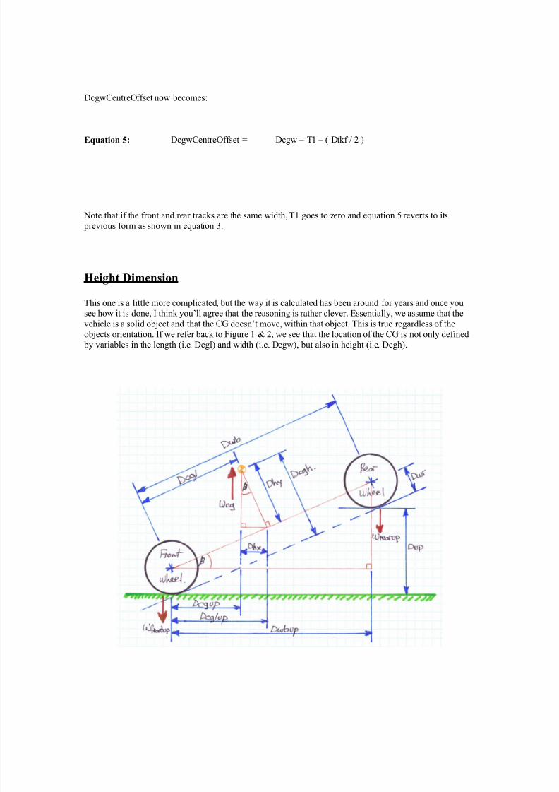
1cgwCentre>ffset now 'ecomes
!uation '" 1cgwCentre>ffset : 1cgw ? 3 ? ( 1tf @ 4 )
ote that if the front and rear tracs are the same width, 3 goes to zero and euation reverts to its
previous form as shown in euation =.
(eight Dimension
his one is a little more complicated, 'ut the way it is calculated has 'een around for years and once you
see how it is done, ! thin you"ll agree that the reasoning is rather clever. Dssentially, we assume that the
vehicle is a solid o'Bect and that the CG doesn"t move, within that o'Bect. his is true regardless of the
o'Bects orientation. !f we refer 'ac to Figure 3 E 4, we see that the location of the CG is not only defined
'y varia'les in the length (i.e. 1cgl) and width (i.e. 1cgw), 'ut also in height (i.e. 1cgh).

8/13/2019 Vehicle Dynamics Estimation
http://slidepdf.com/reader/full/vehicle-dynamics-estimation 9/10
Figure '
o find the height of the CG, we need to lift one end of the car (in this case the rear) and weigh all four
wheels again using the same scales as 'efore. For 'est results it is necessary to immo'ilize the suspension
so that the springs do not compress. /pring compression changes the relationship of the wheel to the 'ody
and therefore also the CG. +y su'stituting the new weight measurements, we can find the $new& horizontal
dimension of the CG (ie. 1cgup) and produce the following euation
!uation )" 1cgup : 1w'up 9 0rearup
0frontup 8 0rearup
*sing the same reasoning that was applied to the derivation of euation 3, we now that the following
definitions hold
0frontup : 0flup 8 0frup
0rearup : 0rlup 8 0rrup
*sing similar triangles we now that the triangle with hypotenuse : 1w' and 6dBacent side : 1w'up is
similar to the triangle with hypotenuse : 1cgh and >pposite side : 1h# and the triangle with ypotenuse :
1cgl and 6dBacent side : 1cglup. For each triangle, the angle shown as +eta is also eual.
Looing at the diagram, we can see that the following conditions hold
1cgh : 1hy 8 1wr
1h# : 1cglup - 1cgup
/in( +eta ) : 1h# @ 1hy : 1hy : 1h# @ /in( +eta )
Cos( +eta ) : 1cglup @ 1cgl : 1cglup : 1cgl 9 Cos( +eta )
/u'stituting and simplifying
1cgh : (( 1cglup ? 1cgup ) @ /in( +eta ) 8 1wr
1cgh : (( 1cgl 9 Cos( +eta )) @/in( +eta ) ) ? ( 1cgup @ /in( +eta )) 8 1wr
1cgh : ( 1cgl @ an( +eta ) ) ? ( 1cgup @ /in( +eta ) ) 8 1wr
Furthermore we now that
/in( +eta ) : 1up @ 1w'

8/13/2019 Vehicle Dynamics Estimation
http://slidepdf.com/reader/full/vehicle-dynamics-estimation 10/10
an( +eta ) : 1up @ 1w'up
/u'stituting further
1cgh : (( 1cgl 9 1w'up ) @ 1up ) ? (( 1cgup 9 1w' ) @ 1up ) 8 1wr
Finally, su'stituting into euation 5 and simplifying a little we derive the final euation
!uation *" 1cgh:
( 1cgl 9 1w'up ) 8 (( 1w'up 9 0rearup ) 9 1w' ) 8 1wr
1up ( 1up 9 ( 0frontup 8 0rearup ) )
Conclusion
here you have it. +y plugging a num'er of relatively simple measurements into the three main euations
( 3, 4 E H ), we can determine ( in theory ) the e#act location of the CG of any four wheeled vehicle.
6uthor %ar Dl'ers
1isclaimer !"m not an engineer, Bust a guy with access to relevant technical documentation and a sense of
curiosity. his article presents my thoughts, 'ased on the research and general reading that !"ve performed
on this topic. !f you find errors in my wor ! would appreciate hearing from you. ! can 'e contacted throughthe 000D1GD e-mail list (trIJmercury.lcs.mit.edu).