Vector III Instruction Manual - RC-Sailplane … Instruction...Sand it carefully if it’s too...
21
Vector III Instruction Manual Vector III is a CNC machine moulded, CAD designed slope aerobatics model aircraft. This plane has had a development period of over 20 years, and three separate models to evolve into the highly agile thoroughbred that you now own. We hope you have a lot of fun with it. James D. Hammond PhD, DBA – designer RCRCM Aeroteam, proud manufacturers. Yes! It’s the very first one with me holding it! Top picture is the incredible Greg Dakin flying another prototype (Photo from Kevin Newton)
Transcript of Vector III Instruction Manual - RC-Sailplane … Instruction...Sand it carefully if it’s too...

Vector III Instruction Manual
Vector III is a CNC machine moulded, CAD designed slope aerobatics model aircraft. This plane has had a development period of over 20 years, and three separate models to evolve into the highly agile thoroughbred that you now own. We hope you have a lot of fun with it.
James D. Hammond PhD, DBA – designer
RCRCM Aeroteam, proud manufacturers.
Yes! It’s the very first one with me holding it!
Top picture is the incredible Greg Dakin flying another prototype
(Photo from Kevin Newton)

Unpacking
• Please unpack the plane carefully making sure that you have
retrieved all of the small parts.
• Don’t throw the box out until you are 100% sure it’s empty!
• Check that all the parts are supplied.
• If any are missing please contact your vendor immediately.
Vector III parts

Before construction
• Start with a clean workbench and cover it with some foam, or a
soft thick cloth to protect the finish of the wings and fuselage as
you work.
• Be careful not to place the wings or fuselage on any screws or
tools etc that can dent or scratch the skin.
• Be very careful using epoxy and CA so that you don't get any on
to the surfaces of the model during assembly.
• You can tick off the bullet points on this instruction manual if you
want to follow it to the letter.
• Remember - check twice – cut once!
Soft quilting to protect your baby!
Wing Construction
I always begin with the wings because it gives that “already half
done” feeling.
Wings:

• First, do a dry assembly to make sure that the entire plane fits
together well. If the carbon joiner seems too tight – it probably
is not. They tend to loosen a little after a few flights – but adding
some floor or car wax can help if it is particularly stiff.
• Check the control surfaces to make sure that they have enough
“up” movement.
• If not, then open up the controls surface to expose the wipers,
then carefully sand the wiper back a little and try again.
• When you are happy, use an air gun or similar to blow the
sanding dust away.
• Install the control rods on each surface using the control horns
that are already installed. Check that they don’t bind in any way.
Control rod installed
Check for enough movement Sand the wipers if not enough
• Next, make up control rods and clevises using the parts supplied.

• The flap rods should be about 85mm and the ailerons about
65mm including clevis length - but check before you cut!
• Make sure you have adjustment at both clevis ends!
Control horns for ailerons and flaps
• Zero the servos by using your R/C unit.
• Remember! Aileron servo arms can be set to 90 degrees, but the
flaps need to have about a 20 degree offset towards the leading
edge and set at + 35 degrees.

Servo control rod and offset detail
• Make up your own, or use the RCRCM wiring harness and check
continuity before installing.
• I use a thin piece of piano wire to thread through the wing plug
holes to tape the wiring harness to pull it into position, servo
plugs first.
• When the wiring harness is positioned inside the wing and
accessible, servos can be installed.
• First, check the position of the plywood servo mounts and check
that the servos fit them.
• Install the control rods on to the servos and check that they do
not bind, are snug but not too loose or to tight.
• Tape the control surfaces flat with masking tape.
• Assemble the completed set of servos, servo mounts and control
rods. Screw the servos to the mounts at this time too.

• When you are satisfied that you have the correct position for the
servo mounts – glue them in using a slow set epoxy, or thick
Cyano. Don’t use 5-minute epoxy because it will probably let go
– at just the wrong time! Be careful not to use too much glue
otherwise you will permanently set the servos.
• When cured and secure, mount the servos, connect them to the
wring harness and check for zeros, then for free and adequate
movement. Adjust using the clevises if needed. (See the control
settings section a the back of this manual for control movements)
• Finally, check the fit of the servo hatch covers and sand if not
snug.
• Then put some double sided tape on the underside and install all
on to the servos hatches.
WINGS DONE! CONGRATULATIONS!
Fuselage construction:
Canopy:
• Start with the canopy – it’s fast and easy!
• First check the canopy fit. Sand it carefully if it’s too large. Take
time on this because nothing looks worse than a badly fitted
canopy.
• If the canopy has distorted and seems to wide – use a hairdryer
(carefully) to warm it up and squeeze it back to shape.

Canopy distorted – use a hairdryer and squeeze it back!
• When you are completely satisfied with the fit, bend the supplied
wire to the shape of the inside of the canopy remembering to
leave wire equally at both front and rear ends.
• When you are happy with the wire fit, there are two ways to
secure it: Epoxy blobs or glass fibre patches. For speed I used
glass fibre set with cyano which works well and is a 1 minute job.
Be carful with that cyano!
Canopy with wire fitted but not installed.
• Check that the canopy fits and is secure.
Another job well done!
Rudder and elevator controls:
• The elevator carbon snake or carbon rod should be already
connected to the machined elevator bellcrank and bearing
assembly. Check that it moves smoothly. If not, some Teflon
spray will normally free it up. Be careful with this if you use it.
It’s quite possible to make it impossible to glue anything to
the fuselage!
• Do a trial assembly with the tailplane halves and check for
smooth movement.
• OK? Now for the rudder.
• First remove the control rod or snake inner.
• Attach the clevis to the rod with thick cyano, and when cured
– test that it is very well secured by pulling on it as hard as
you can!
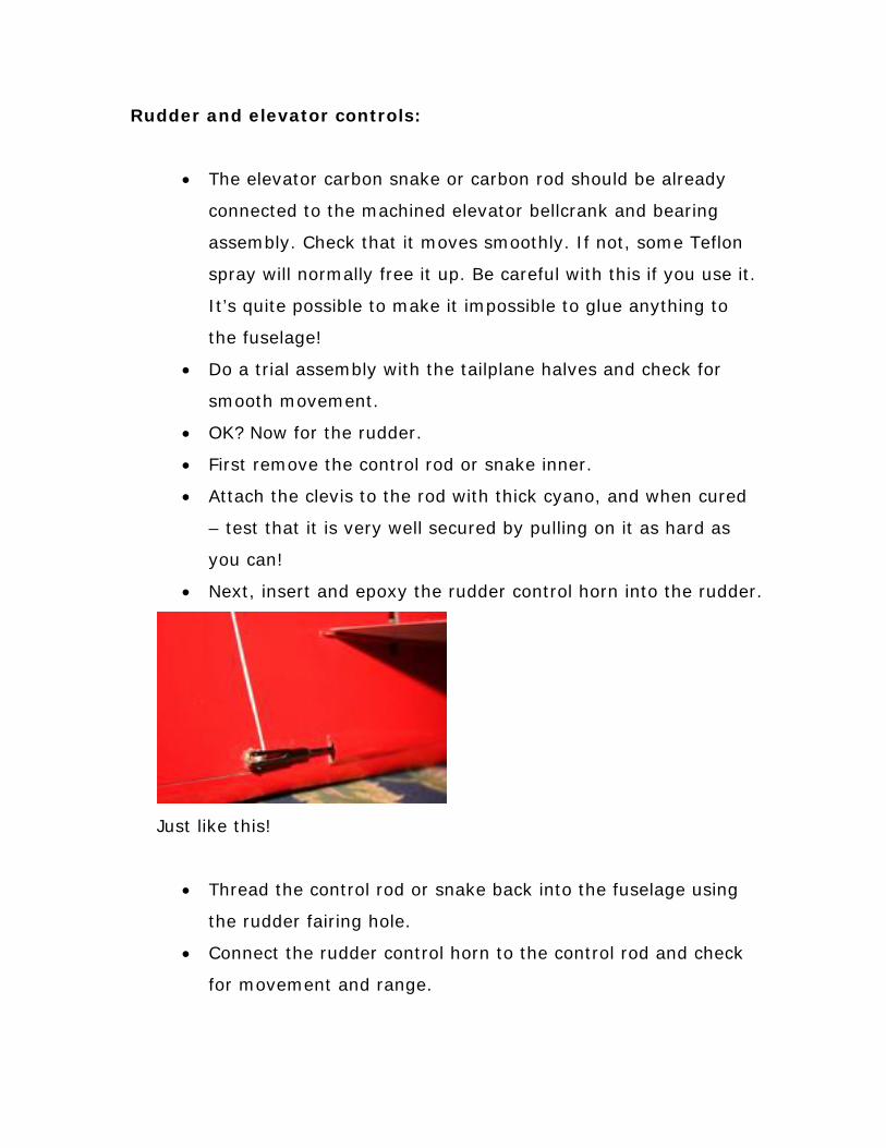
• Next, insert and epoxy the rudder control horn into the rudder.
Just like this!
• Thread the control rod or snake back into the fuselage using
the rudder fairing hole.
• Connect the rudder control horn to the control rod and check
for movement and range.
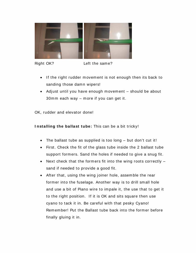
Right OK? Left the same?
• If the right rudder movement is not enough then its back to
sanding those damn wipers!
• Adjust until you have enough movement – should be about
30mm each way – more if you can get it.
OK, rudder and elevator done!
Installing the ballast tube: This can be a bit tricky!
• The ballast tube as supplied is too long – but don’t cut it!
• First. Check the fit of the glass tube inside the 2 ballast tube
support formers. Sand the holes if needed to give a snug fit.
• Next check that the formers fit into the wing roots correctly –
sand if needed to provide a good fit.
• After that, using the wing joiner hole, assemble the rear
former into the fuselage. Another way is to drill small hole
and use a bit of Piano wire to impale it, the use that to get it
to the right position. If it is OK and sits square then use
cyano to tack it in. Be careful with that pesky Cyano!
Remember! Put the Ballast tube back into the former before
finally gluing it in.

Yeah…take time – I know it’s fiddly!
• When you are 100% satisfied with the rear former position
weld it in with thick slow set epoxy, this can be done with a
dowel or a chopstick with epoxy blobs carefully daubed and
smoothed until it’s nicely fixed.
• OK when the rear former is in place, remove the ballast tube
and put in the front former.
• Cyano tack the front former in position. Careful! Watch that
cyano!
• Then check that the ballast tube still fits!
• If it’s OK, then you can now finally slow set epoxy the front
former in. Easy compared to the rear one right?
• Now the ballast tube can be finally positioned, cut to suit a CG
of 95mm and then epoxied in. You cab dab a bit of epoxy at
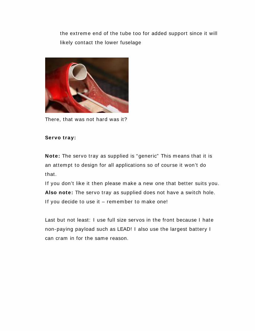
the extreme end of the tube too for added support since it will
likely contact the lower fuselage
There, that was not hard was it?
Servo tray:
Note: The servo tray as supplied is “generic” This means that it is
an attempt to design for all applications so of course it won’t do
that.
If you don’t like it then please make a new one that better suits you.
Also note: The servo tray as supplied does not have a switch hole.
If you decide to use it – remember to make one!
Last but not least: I use full size servos in the front because I hate
non-paying payload such as LEAD! I also use the largest battery I
can cram in for the same reason.

An example of a self-made servo tray – whatever turns you on!
• First check the fit of the servo tray inside the fuselage in the
position you like.
• Sand the edges to a gentle curve to fit snugly inside the
fuselage.
• Now fit the servos and adjust the height of the tray to best
connect the servos to the snakes or control rods.
• When you have it right and square, pencil a line where it fits
on both sides of the cockpit wall.
• Now sand a chamfer all along the sides, maybe 3mm deep.
This will help the epoxy to bond it to the fuselage sides.
See the Chamfer? Yep – just like that.
• OK, now remove the servos and tack cyano the tray into the
fuselage.
• Check it again!

• If it’s OK then slow-set epoxy it in.
• After the epoxy has set, you might like to apply a coat of
varnish or paint to keep moisture out.
Done!
Installing the rudder/elevator pushrods or snakes to the
servos
• Set the rudder and the elevator to zero and tape them that
way.
• Install the servos and use your RC unit to set them to zero.
• Then simply cut the rods or snakes to fit, remembering to
leave space for the adjustment clevis.
• Check for movement and adjust accordingly.
Note that this builder has spiffed it up with some carbon!
Done!
Installing the wiring harness

• Use the RCRM wiring harness or make your own.
• Check continuity!
• Check that the wiring harness connectors fit snugly into
the fuselage connector holes.
• If not…file the holes out until they do.
• Thread the plugs through into the fuselage and rout the
receiver plugs to the receiver area.
• Put in the receiver and battery temporarily and make sure
the whole shebang actually works!
• Now cyano the connectors into the holes.
Done! Neat huh?
Battery Installation
I made a couple of formers to keep the battery with holes in
them so that I could use tie wraps to keep it in one place. It gets
really boring when you are flying inverted and the battery
ejects…

Examples of other battery/servo setups
Nose weight
This can be custom made or just fishing weights etc – but it will
need to be around 14 ounces.
Here we will deal with the custom made version
• First, fill a paper (not plastic!) cup with sand – not too wet,
just damp. Alternatively an antique bone china coffee cup
will do.

There, see the impression of the nose?
• Then push the nose of the plane into the cup about 2
inches (50mm) and take it out to leave an impression or
mould.
• Using your wife’s best saucepans, melt about a pound
(0.5KG) of lead and then – careful! Stand as far away as
possible and use eye protection! – pour the lead into the
mould.
• When its set (give it at least 5 minutes) bung it into the
sink and cool it with water:
Not too bad! Cool maybe?
Now for the last part:
• Trial fit the nose weight into the fuselage. Note that you
can fettle it with a hammer if it’s a bit too big:

Bit of a banger huh?
• Now fully assemble the plane and test the CG (95mm from
the Leading edge at the root)
• Add or remove weight until the plane balances correctly.
• When satisfied, epoxy the nose weight in.
Just like that! Neat or what?
Important note: Whatever you do, never make the nose weight too
heavy – its better to have a slightly underweight nose with a bit of
lead added than it is to have to drill out lead from a too heavy nose.
Wow…looks like it time to go and test it!


Crikey...she flies!
Now you might need the last bit:
Control surface movements and CG settings
C/G = *95mm from Leading Edge to start. Move back slowly in small increments to further improve responses. *Note…for those conservatives, or possibly less experienced among us, it might be better to start at 85mm Control surface settings: (All measured form the outboard trailing edges) GENERAL: Ailerons +/- 20mm

Flaperon +/- 12 mm Rudder – As much as possible Elevator +/- 12 mm CROW Crow- Flap -50 mm or more if desired Crow-Aileron +10 mm Crow-Elevator compensation -4 mm THERMAL (WHAT?) OR PUSSYCAT Thermal or Cruise flap -10 mm Thermal or Cruise Aileron -5mm AEROBATICS Aerobatics - coupled flap and elevator +/- 18 mm – snap flap works well too. Finally, thanks to all those whose photographs I have shamelessly stolen for use here!
James Hammond, February 2009


![7 3 Sailplane GP-1 [Mode de compatibilité]...Sailplane Grand Prix 2014 World Sailplane Grand Prix Final 2014-2015 Qualifying Sailplane Grand Prix series 2015 World Sailplane Grand](https://static.fdocuments.in/doc/165x107/6023534700029d297b3d533e/7-3-sailplane-gp-1-mode-de-compatibilit-sailplane-grand-prix-2014-world.jpg)