VE V6 Vortech Intercooler Kit Manual · 10. Never strike the supercharger pulley with a hammer or...
9
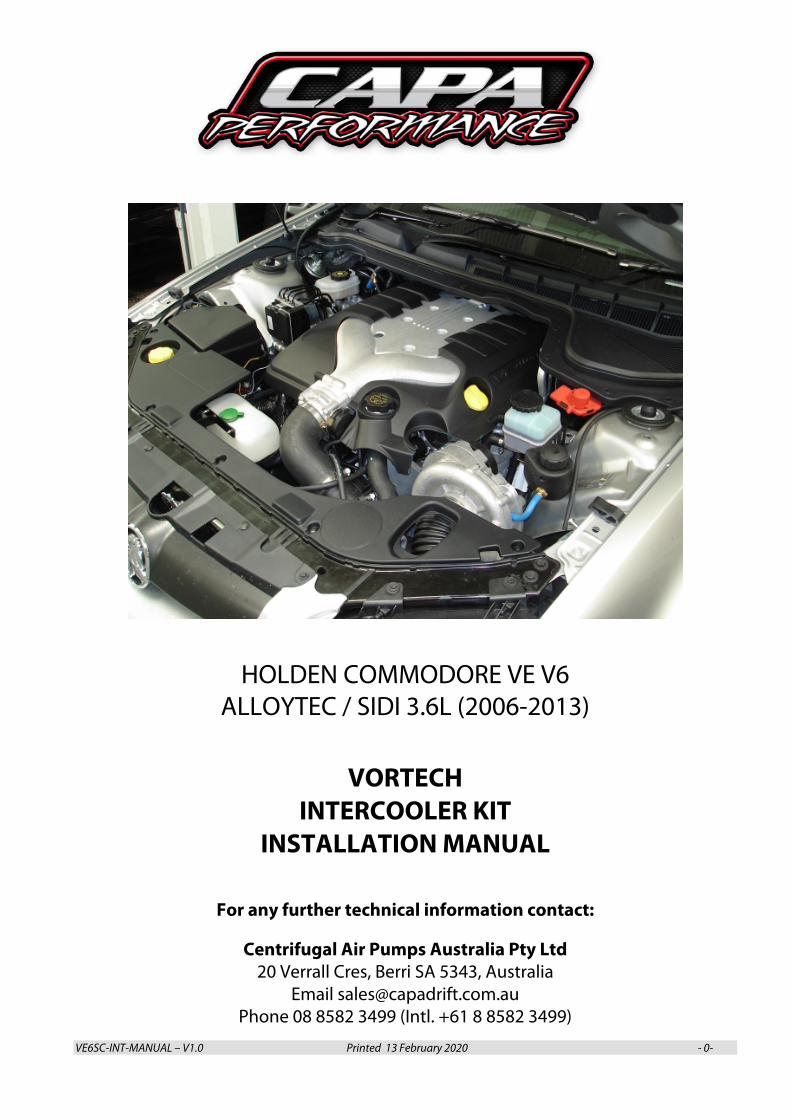
VE6SC-INT-MANUAL – V1.0 Printed 13 February 2020 - 0- HOLDEN COMMODORE VE V6 ALLOYTEC / SIDI 3.6L (2006-2013) VORTECH INTERCOOLER KIT INSTALLATION MANUAL For any further technical information contact: Centrifugal Air Pumps Australia Pty Ltd 20 Verrall Cres, Berri SA 5343, Australia Email [email protected] Phone 08 8582 3499 (Intl. +61 8 8582 3499)
Transcript of VE V6 Vortech Intercooler Kit Manual · 10. Never strike the supercharger pulley with a hammer or...
VE6SC-INT-MANUAL – V1.0 Printed 13 February 2020 - 0-
HOLDEN COMMODORE VE V6 ALLOYTEC / SIDI 3.6L (2006-2013)
VORTECH
INTERCOOLER KIT INSTALLATION MANUAL
For any further technical information contact:
Centrifugal Air Pumps Australia Pty Ltd 20 Verrall Cres, Berri SA 5343, Australia
Email [email protected] Phone 08 8582 3499 (Intl. +61 8 8582 3499)
VE6SC-INT-MANUAL – V1.0 Printed 13 February 2020 - 1-
INTRODUCTION
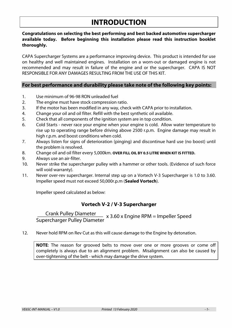
Congratulations on selecting the best performing and best backed automotive supercharger available today. Before beginning this installation please read this instruction booklet thoroughly. CAPA Supercharger Systems are a performance improving device. This product is intended for use on healthy and well maintained engines. Installation on a worn-out or damaged engine is not recommended and may result in failure of the engine and or the supercharger. CAPA IS NOT RESPONSIBLE FOR ANY DAMAGES RESULTING FROM THE USE OF THIS KIT. For best performance and durability please take note of the following key points: 1. Use minimum of 96-98 RON unleaded fuel 2. The engine must have stock compression ratio. 3. If the motor has been modified in any way, check with CAPA prior to installation. 4. Change your oil and oil filter. Refill with the best synthetic oil available. 5. Check that all components of the ignition system are in top condition. 6. Cold Starts - never race your engine when your engine is cold. Allow water temperature to
rise up to operating range before driving above 2500 r.p.m. Engine damage may result in high r.p.m. and boost conditions when cold.
7. Always listen for signs of deterioration (pinging) and discontinue hard use (no boost) until the problem is resolved.
8. Change oil and oil filter every 5,000km. OVER FILL OIL BY 0.5 LITRE WHEN KIT IS FITTED. 9. Always use an air-filter. 10. Never strike the supercharger pulley with a hammer or other tools. (Evidence of such force
will void warranty). 11. Never over-rev supercharger. Internal step up on a Vortech V-3 Supercharger is 1.0 to 3.60.
Impeller speed must not exceed 50,000r.p.m (Sealed Vortech). Impeller speed calculated as below:
Vortech V-2 / V-3 Supercharger
Crank Pulley Diameter Supercharger Pulley Diameter
12. Never hold RPM on Rev Cut as this will cause damage to the Engine by detonation.
NOTE: The reason for grooved belts to move over one or more grooves or come off completely is always due to an alignment problem. Misalignment can also be caused by over-tightening of the belt - which may damage the drive system.
x 3.60 x Engine RPM = Impeller Speed
VE6SC-INT-MANUAL – V1.0 Printed 13 February 2020 - 2-
GLOSSARY
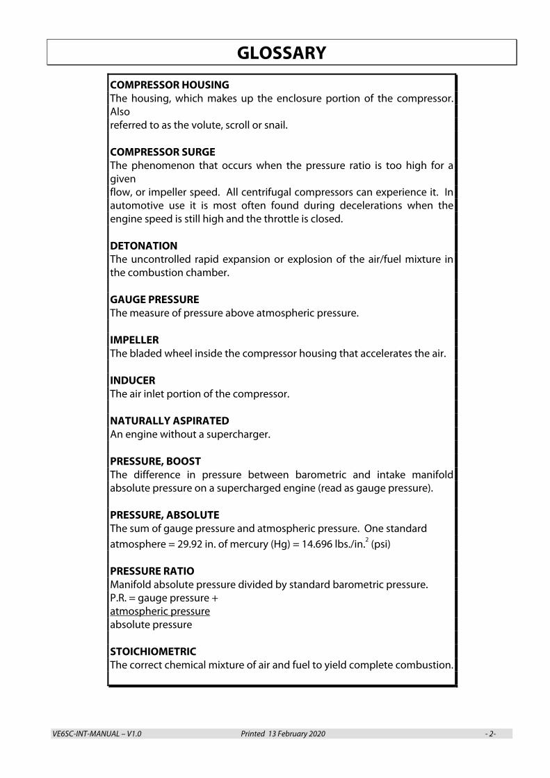
COMPRESSOR HOUSING The housing, which makes up the enclosure portion of the compressor. Also referred to as the volute, scroll or snail. COMPRESSOR SURGE The phenomenon that occurs when the pressure ratio is too high for a given flow, or impeller speed. All centrifugal compressors can experience it. In automotive use it is most often found during decelerations when the engine speed is still high and the throttle is closed. DETONATION The uncontrolled rapid expansion or explosion of the air/fuel mixture in the combustion chamber. GAUGE PRESSURE The measure of pressure above atmospheric pressure. IMPELLER The bladed wheel inside the compressor housing that accelerates the air. INDUCER The air inlet portion of the compressor. NATURALLY ASPIRATED An engine without a supercharger. PRESSURE, BOOST The difference in pressure between barometric and intake manifold absolute pressure on a supercharged engine (read as gauge pressure). PRESSURE, ABSOLUTE The sum of gauge pressure and atmospheric pressure. One standard atmosphere = 29.92 in. of mercury (Hg) = 14.696 lbs./in.2 (psi) PRESSURE RATIO Manifold absolute pressure divided by standard barometric pressure. P.R. = gauge pressure + atmospheric pressure absolute pressure STOICHIOMETRIC The correct chemical mixture of air and fuel to yield complete combustion.
VE6SC-INT-MANUAL – V1.0 Printed 13 February 2020 - 3-
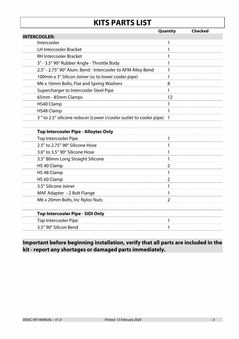
KITS PARTS LIST Quantity Checked
INTERCOOLER: Intercooler 1 LH Intercooler Bracket 1 RH Intercooler Bracket 1
3" - 3.5" 90° Rubber Angle - Throttle Body 1 2.5" - 2.75" 90° Alum. Bend - Intercooler to AFM Alloy Bend 1 100mm x 3” Silicon Joiner (sc to lower cooler pipe) 1
M6 x 16mm Bolts, Flat and Spring Washers 8 Supercharger to Intercooler Steel Pipe 1 65mm - 85mm Clamps 12 HS40 Clamp 1 HS48 Clamp 1 3 ” to 2.5” silicone reducer (Lower i/cooler outlet to cooler pipe) 1
Top Intercooler Pipe - Alloytec Only Top Intercooler Pipe 1 2.5” to 2.75” 90° Silicone Hose 1 3.0” to 3.5” 90° Silicone Hose 1 3.5” 80mm Long Straight Silicone 1 HS 40 Clamp 2 HS 48 Clamp 1 HS 60 Clamp 2 3.5" Silicone Joiner 1 MAF Adapter - 2 Bolt Flange 1 M6 x 20mm Bolts, Inc Nyloc Nuts 2
Top Intercooler Pipe - SIDI Only Top Intercooler Pipe 1 3.5” 90° Silicon Bend 1
Important before beginning installation, verify that all parts are included in the kit - report any shortages or damaged parts immediately.
VE6SC-INT-MANUAL – V1.0 Printed 13 February 2020 - 4-
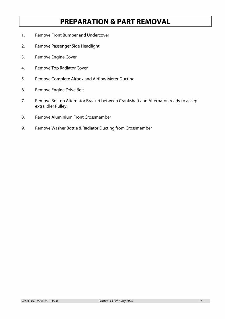
PREPARATION & PART REMOVAL 1. Remove Front Bumper and Undercover
2. Remove Passenger Side Headlight
3. Remove Engine Cover
4. Remove Top Radiator Cover
5. Remove Complete Airbox and Airflow Meter Ducting
6. Remove Engine Drive Belt 7. Remove Bolt on Alternator Bracket between Crankshaft and Alternator, ready to accept
extra Idler Pulley.
8. Remove Aluminium Front Crossmember
9. Remove Washer Bottle & Radiator Ducting from Crossmember
VE6SC-INT-MANUAL – V1.0 Printed 13 February 2020 - 5-
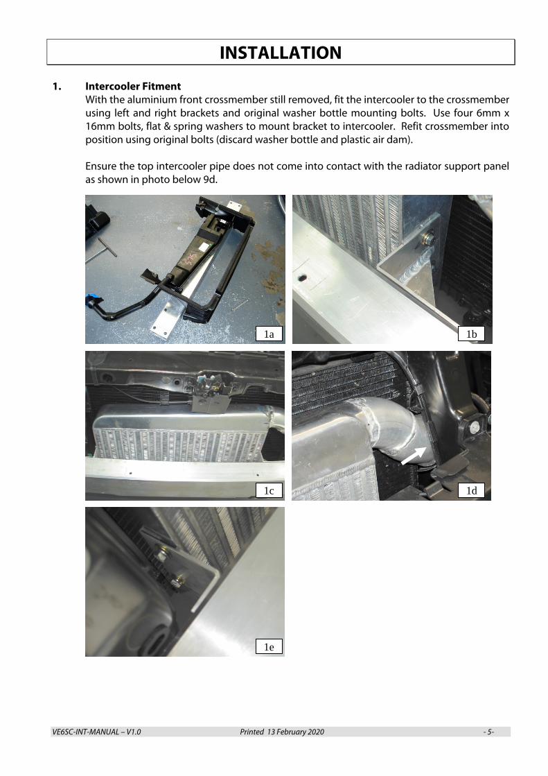
INSTALLATION 1. Intercooler Fitment
With the aluminium front crossmember still removed, fit the intercooler to the crossmember using left and right brackets and original washer bottle mounting bolts. Use four 6mm x 16mm bolts, flat & spring washers to mount bracket to intercooler. Refit crossmember into position using original bolts (discard washer bottle and plastic air dam). Ensure the top intercooler pipe does not come into contact with the radiator support panel as shown in photo below 9d.
1a 1b
1c 1d
1e
VE6SC-INT-MANUAL – V1.0 Printed 13 February 2020 - 6-
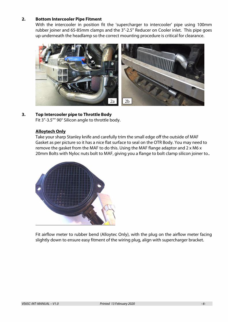
2. Bottom Intercooler Pipe Fitment With the intercooler in position fit the ‘supercharger to intercooler’ pipe using 100mm rubber joiner and 65-85mm clamps and the 3”-2.5” Reducer on Cooler inlet. This pipe goes up underneath the headlamp so the correct mounting procedure is critical for clearance.
3. Top Intercooler pipe to Throttle Body
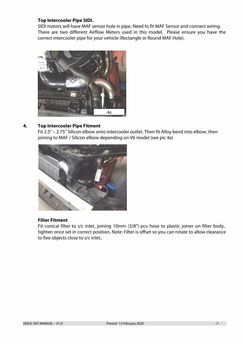
Fit 3”-3.5”” 90° Silicon angle to throttle body. Alloytech Only Take your sharp Stanley knife and carefully trim the small edge off the outside of MAF Gasket as per picture so it has a nice flat surface to seal on the OTR Body. You may need to remove the gasket from the MAF to do this. Using the MAF flange adaptor and 2 x M6 x 20mm Bolts with Nyloc nuts bolt to MAF, giving you a flange to bolt clamp silicon joiner to..
Fit airflow meter to rubber bend (Alloytec Only), with the plug on the airflow meter facing slightly down to ensure easy fitment of the wiring plug, align with supercharger bracket.
2b2a
VE6SC-INT-MANUAL – V1.0 Printed 13 February 2020 - 7-
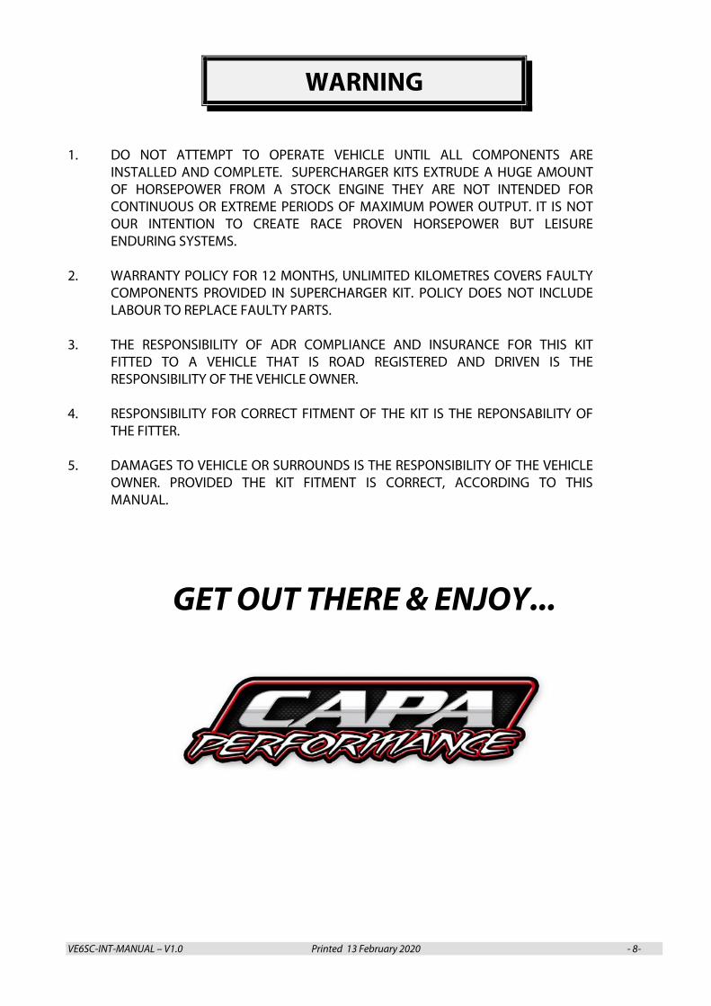
Top Intercooler Pipe SIDI. SIDI motors will have MAF sensor hole in pipe. Need to fit MAF Sensor and connect wiring. There are two different Airflow Meters used in this model. Please ensure you have the correct intercooler pipe for your vehicle (Rectangle or Round MAF Hole).
4. Top Intercooler Pipe Fitment
Fit 2.5” – 2.75” Silicon elbow onto intercooler outlet. Then fit Alloy bend into elbow, then joining to MAF / Silicon elbow depending on V6 model (see pic 4a)
Filter Fitment Fit conical filter to s/c inlet, joining 10mm (3/8”) pcv hose to plastic joiner on filter body.. tighten once set in correct position. Note: Filter is offset so you can rotate to allow clearance to fixe objects close to s/c inlet..
4a
VE6SC-INT-MANUAL – V1.0 Printed 13 February 2020 - 8-
WARNING
1. DO NOT ATTEMPT TO OPERATE VEHICLE UNTIL ALL COMPONENTS ARE INSTALLED AND COMPLETE. SUPERCHARGER KITS EXTRUDE A HUGE AMOUNT OF HORSEPOWER FROM A STOCK ENGINE THEY ARE NOT INTENDED FOR CONTINUOUS OR EXTREME PERIODS OF MAXIMUM POWER OUTPUT. IT IS NOT OUR INTENTION TO CREATE RACE PROVEN HORSEPOWER BUT LEISURE ENDURING SYSTEMS.
2. WARRANTY POLICY FOR 12 MONTHS, UNLIMITED KILOMETRES COVERS FAULTY
COMPONENTS PROVIDED IN SUPERCHARGER KIT. POLICY DOES NOT INCLUDE LABOUR TO REPLACE FAULTY PARTS.
3. THE RESPONSIBILITY OF ADR COMPLIANCE AND INSURANCE FOR THIS KIT
FITTED TO A VEHICLE THAT IS ROAD REGISTERED AND DRIVEN IS THE RESPONSIBILITY OF THE VEHICLE OWNER.
4. RESPONSIBILITY FOR CORRECT FITMENT OF THE KIT IS THE REPONSABILITY OF
THE FITTER. 5. DAMAGES TO VEHICLE OR SURROUNDS IS THE RESPONSIBILITY OF THE VEHICLE
OWNER. PROVIDED THE KIT FITMENT IS CORRECT, ACCORDING TO THIS MANUAL.
GET OUT THERE & ENJOY...