
VCO-1, VCO-8, VCO-16 · VCO-1, VCO-8, VCO-16 – Contents i Contents 1 Introduction 1 2 Getting...
99
USER MANUAL MODELS: VCO-1, VCO-8, VCO-16 Video Content Overlay Solution P/N: 2900-300592 Rev 1 www.kramerAV.com
Transcript of VCO-1, VCO-8, VCO-16 · VCO-1, VCO-8, VCO-16 – Contents i Contents 1 Introduction 1 2 Getting...

USER MANUAL
MODELS:
VCO-1, VCO-8, VCO-16 Video Content Overlay Solution
P/N: 2900-300592 Rev 1 www.kramerAV.com

VCO-1, VCO-8, VCO-16 – Contents i
Contents 1 Introduction 1 2 Getting Started 2 2.1 Achieving the Best Performance 2 2.2 Safety Instructions 3 2.3 Recycling Kramer Products 3 3 Overview 4 3.1 Defining the Video Content Overlay Solution 6 4 Installing the VCO-8 and VCO-16 in a Rack 9 5 Connecting the VCO-1, VCO-8, VCO-16 10 5.1 Connecting the VCO-8 / VCO-16 10 5.2 Connecting the VCO-1 12 6 Looping the VCO-8 and VCO-16 13 7 Using the Kramer VCO Setup Application 15 7.1 Install the VCO Setup Application 15 7.2 Setup & About 19 7.3 Setting the Overlays 32 7.4 Scheduling the Overlays 56 8 Defining an IP Address for a Device 66 8.1 Setting a Static IP Address 66 8.2 Operating via the Ethernet 70 9 Technical Specifications 75 9.1 Default Communication Parameters 76 10 Communication Protocol 77 10.1 Understanding Protocol 3000 78 10.2 Kramer Protocol 3000 Syntax 80 10.3 Protocol 3000 Commands 81
Figures Figure 1: VCO-1 Front and Rear Panels 6 Figure 2: VCO-8 and VCO-16 Front Panels 7 Figure 3: VCO-8 and VCO-16 Rear Panels 8 Figure 4: Connecting the VCO-8 / VCO-16 11 Figure 5: Connecting the VCO-1 12 Figure 6: A Set of 2 Looped VCO-16 Units 14 Figure 7: Installing the VCO Setup App - Warning 16 Figure 8: Installing the VCO Setup App – Setup Application Description 16 Figure 9: Installing the VCO Setup App – Legal info 16 Figure 10: Installing the VCO Setup App – Setting the Destination Folder 17 Figure 11: Installing the VCO Setup App– Installing the Software 17 Figure 12: Installing the VCO Setup App – Installation is Complete 17 Figure 13: Installing the VCO Setup App – The Setup & About Tab 18 Figure 14: Setup & About Tab 19 Figure 15: Setup & About – Selecting the Language 19 Figure 16: Welcome to Device Wizard 20 Figure 17: Device Wizard 21 Figure 18: Device Wizard – Add Device Manually 22

ii VCO-1, VCO-8, VCO-16 - Contents
Figure 19: Device Wizard – Selecting a Device 22 Figure 20: Device Wizard – Device Selected 23 Figure 21: Device Wizard – Setting the IP Address 23 Figure 22: Device Wizard – Setting the Lower Number of the IP address. 24 Figure 23: Device Wizard – Setting the Higher parts of the IP Address 25 Figure 24: Device Wizard – Changing the IP Address 25 Figure 25: Device Wizard – Changing the Higher Parts of the IP Address 26 Figure 26: Changing the IP Address Message 26 Figure 27: Device Wizard – Changing the IP Address Higher Parts 27 Figure 28: Device Wizard – Testing the IP Address Change 27 Figure 29: Device Wizard Setting the Recommended Name 28 Figure 30: Device Wizard – Set the Device Name 28 Figure 31: Device Wizard – Device Installed 29 Figure 32: Device Wizard –Device Details 29 Figure 33: Device Wizard – Automatic IP Address Detection 30 Figure 34: Device Wizard – Searching for an IP Address 30 Figure 35: Device Wizard – Device IP Address Detected 31 Figure 36: Device Wizard –The Device Details (following Automatic Scan) 31 Figure 37: Setting the Overlays – Right-Clicking the All Overlays folder 32 Figure 38: Setting the Overlays – the Overlay Tab 33 Figure 39: Setting the Overlays – Create a New Folder 33 Figure 40: Setting the Overlays – New Folder Added 34 Figure 41: Setting the Overlays – the Overlay Tab 34 Figure 42: Setting the Overlays – the Add New Overlay Window 35 Figure 43: Setting the Overlays – Add a New Name and Description 35 Figure 44: Setting the Overlays – The Overlay Added to the Overlay List 36 Figure 45: Setting the Overlays – Template Details 36 Figure 46: Setting the Overlays – Bind Overlay to Machine 37 Figure 47: Setting the Overlays – the Overlay Settings 38 Figure 48: Setting the Overlays – Building Overlay Message 38 Figure 49: Setting the Overlays – Rendering the Overlay 39 Figure 50: Setting the Overlays – View of the Overlay 39 Figure 51: Adding a New/External Template – Launching the Template Wizard 40 Figure 52: Adding a New/External Template – Template Wizard 40 Figure 53: Adding a New/External Template – Available File Operations 41 Figure 54: Adding a New/External Template – Available Folder Operations 41 Figure 55: Adding a New/External Template – Ready-to-Use Template – External Source 42 Figure 56: Adding a New/External Template – Selecting the Folder 42 Figure 57: Adding a New/External Template – Selecting the Template 43 Figure 58: Adding a New/External Template – Available Operations 43 Figure 59: Adding a New/External Template – New Template Added 44 Figure 60: Creating a New Overlay 44 Figure 61: Template Wizard – Setting the Resolution 45 Figure 62: Template Wizard – Adding and Editing Window 45 Figure 63: Template Wizard – Editing the PNG graphic 47 Figure 64: Template Wizard – Resizing Options 48 Figure 65: Template Wizard – Adding Graphics 48 Figure 66: Template Wizard – Create Playback Program 49 Figure 67: Template Wizard – Add Template Description and see Preview 50 Figure 68: New Template Added 51 Figure 69: Setting the Movement and Transparency – the Program Editor 52 Figure 70: Scheduling Tab 57 Figure 71: Scheduling – Adding an Event 58 Figure 72: Scheduling – Adding Overlays to the Event 59
VCO-1, VCO-8, VCO-16 – Contents iii
Figure 73: Scheduling – Firing an Event 60 Figure 74: Scheduling – Enable Scheduling 61 Figure 75: Setting the IP Address 66 Figure 76: Setting the High Parts of the IP Address 69 Figure 77: DHCP Mode DIP-Switch Setup 70 Figure 78: Local Area Connection Properties Window 72 Figure 79: Internet Protocol Version 4 Properties Window 72 Figure 80: Internet Protocol Version 6 Properties Window 73 Figure 81: Internet Protocol Properties Window 74

VCO-1, VCO-8, VCO-16 – Introduction 1
1 Introduction
Welcome to Kramer Electronics! Since 1981, Kramer Electronics has been
providing a world of unique, creative, and affordable solutions to the vast range of
problems that confront video, audio, presentation, and broadcasting professionals
on a daily basis. In recent years, we have redesigned and upgraded most of our
line, making the best even better!
Our 1,000-plus different models now appear in 14 groups that are clearly defined by
function: GROUP 1: Distribution Amplifiers; GROUP 2: Switchers and Routers;
GROUP 3: Control Systems; GROUP 4: Format/Standards Converters; GROUP 5:
Range Extenders and Repeaters; GROUP 6: Specialty AV Products; GROUP 7:
Scan Converters and Scalers; GROUP 8: Cables and Connectors; GROUP 9:
Room Connectivity; GROUP 10: Accessories and Rack Adapters; GROUP 11:
Sierra Video Products; GROUP 12: Digital Signage; GROUP 13: Audio; and
GROUP 14: Collaboration.
Congratulations on purchasing your Kramer VCO-1, VCO-8, VCO-16 Video Content
Overlay Solution. This product, which incorporates HDMI™ technology, is ideal for:
• Providing visitor information, messages, promotional ads, and emergency announcements overlaid on your current display network
• Hotel lobbies, lounges, guest rooms and conference rooms
• Sports bars, nightclubs, special venues
• Restaurants, cafes, diners
2 VCO-1, VCO-8, VCO-16 - Getting Started
2 Getting Started
We recommend that you:
• Unpack the equipment carefully and save the original box and packaging materials for possible future shipment
• Review the contents of this user manual
• Use Kramer high performance high resolution cables
Go to www.kramerav.com/downloads/VCOs to check for up-to-date user manuals, application programs, and to check if firmware upgrades are available (where appropriate).
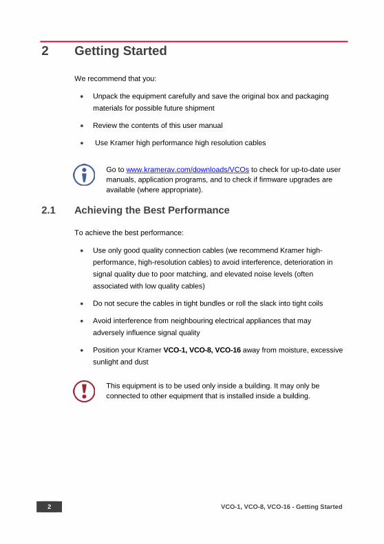
2.1 Achieving the Best Performance
To achieve the best performance:
• Use only good quality connection cables (we recommend Kramer high-performance, high-resolution cables) to avoid interference, deterioration in signal quality due to poor matching, and elevated noise levels (often associated with low quality cables)
• Do not secure the cables in tight bundles or roll the slack into tight coils
• Avoid interference from neighbouring electrical appliances that may adversely influence signal quality
• Position your Kramer VCO-1, VCO-8, VCO-16 away from moisture, excessive sunlight and dust
This equipment is to be used only inside a building. It may only be connected to other equipment that is installed inside a building.
VCO-1, VCO-8, VCO-16 – Getting Started 3
2.2 Safety Instructions
Caution: There are no operator serviceable parts inside the unit
Warning: Use only the power cord that is supplied with the unit
Warning: Do not open the unit. High voltages can cause electrical shock! Servicing by qualified personnel only
Warning: Disconnect the power and unplug the unit from the wall before installing
2.3 Recycling Kramer Products
The Waste Electrical and Electronic Equipment (WEEE) Directive 2002/96/EC aims
to reduce the amount of WEEE sent for disposal to landfill or incineration by
requiring it to be collected and recycled. To comply with the WEEE Directive,
Kramer Electronics has made arrangements with the European Advanced
Recycling Network (EARN) and will cover any costs of treatment, recycling and
recovery of waste Kramer Electronics branded equipment on arrival at the EARN
facility. For details of Kramer’s recycling arrangements in your particular country go
to our recycling pages at www.kramerav.com/support/recycling/.
4 VCO-1, VCO-8, VCO-16 - Overview
3 Overview
Kramer VCO solutions let users display targeted messages across any number of
displays in showrooms, bars, lobbies, or conference rooms. VCO-1, VCO-8, and
VCO-16 are specialized distribution amplifiers that can distribute independent
content layers to 1, 5, 8, or 16 and optionally to any number of displays over
standard HDMI in full HD resolution (1080p60 or 1920x1200).
Simply connect the Kramer VCO to each display with a single HDMI cable, choose
any standard graphics file to be overlaid (such as a reminder that the bar will close
at 11:00pm), and that’s all. The VCO solution also enables scheduling specific
messages to be overlaid on specific displays at any chosen time and provides a set
of overlay templates for initial use.
With centralized control, Kramer VCO solutions let users manage individual video
content overlays for each connected display from anywhere in the world.
With Kramer VCO, you get:
• Comprehensive Digital Overlay Solution:
Complete, project-tailored solution for all your display needs
Support for an unlimited number of overlays and displays
Individual or multi-channel control and centralized operation and management
Precise scheduling of each individual overlay per display
Static or animated dynamic color image overlays in full HD
Multiple overlay templates for multiple applications
Comprehensive error reporting for connected displays and overlays
• Flexible Integration and Usability:
Use with any customer management system
Use your existing display network infrastructure
Supports any-sized content overlays with full transparency control

VCO-1, VCO-8, VCO-16 – Overview 5
Built-in looping output for daisy chaining any number of devices (VCO-8 and VCO-16 only)
• Cost Effective. User-Friendly Operation and Management:
Easy setup with a non-technical, user-friendly and feature-rich interface
Automatically displays engaging static or animated messages and push notification campaigns, full-HD resolution to multiple displays in multiple zones over live video from cameras, satellite receivers, PCs, or media players — in a single click
Simple, cost-effective operation and management — from a single display in a bar to hundreds of displays in a hotel
Problem-free installation, instant error reporting for each display and an international warranty with localized support
VCO-8 and VCO-16 are housed in a 19” 1U rack mountable enclosure with rack
“ears”. They use a 100-240 VAC universal switching power supply.
VCO-1 is housed in a compact TOOLS size. Three units can be rack-mounted side
by side in a 1U rack space with an optional RK-3T rack adapter tool.
6 VCO-1, VCO-8, VCO-16 - Overview
3.1 Defining the Video Content Overlay Solution
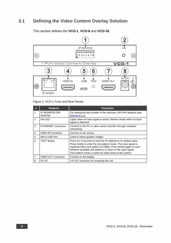
This section defines the VCO-1, VCO-8 and VCO-16.
Figure 1: VCO-1 Front and Rear Panels
# Feature Function 1 IP ADDRESS DIP-
Switches For setting the last number in the machine LAN IPv4 address (see Section 8.1.1)
2 ON LED Lights when an input signal is active; flashes slowly when no input signal is detected
3 ETHERNET Connector Connect to the PC or other serial controller through computer networking
4 HDMI IN Connector Connect to the source 5 Micro USB Port Used to import graphic images 6 TEST Button Press for 5 seconds to reset the IP address to its default value.
Press briefly to enter the test pattern mode. The input signal is replaced with a test pattern at 1080p. Press briefly again to cycle between available test patterns or return to the input signal. Test pattern mode is useful for initial setup of the system
7 HDMI OUT Connector Connect to the display 8 5V DC +5V DC connector for powering the unit

VCO
-1, VCO
-8, VCO
-16 – Overview
7
Figure 2: VCO-8 and VCO-16 Front Panels
# Feature Function 1 INPUT LED Lights when an input signal is active; flashes slowly when no input signal is detected 2 LOOP LED Lights on the looped device when a looped signal is in use 3 OUTPUT STATUS LEDS Lights when an output signal is active 4 USB CONNECTOR Used to import graphic images
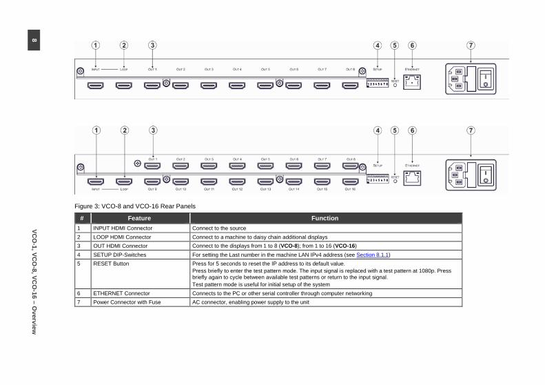
Figure 3: VCO-8 and VCO-16 Rear Panels
# Feature Function 1 INPUT HDMI Connector Connect to the source 2 LOOP HDMI Connector Connect to a machine to daisy chain additional displays 3 OUT HDMI Connector Connect to the displays from 1 to 8 (VCO-8); from 1 to 16 (VCO-16) 4 SETUP DIP-Switches For setting the Last number in the machine LAN IPv4 address (see Section 8.1.1) 5 RESET Button Press for 5 seconds to reset the IP address to its default value.
Press briefly to enter the test pattern mode. The input signal is replaced with a test pattern at 1080p. Press briefly again to cycle between available test patterns or return to the input signal. Test pattern mode is useful for initial setup of the system
6 ETHERNET Connector Connects to the PC or other serial controller through computer networking 7 Power Connector with Fuse AC connector, enabling power supply to the unit
8 VC
O-1, VC
O-8, VC
O-16 – O
verview

VCO-1, VCO-8, VCO-16 - Installing the VCO-8 and VCO-16 in a Rack 9
4 Installing the VCO-8 and VCO-16 in a Rack
This section provides instructions for rack mounting the unit.
10 VCO-1, VCO-8, VCO-16 - Connecting the VCO-1, VCO-8, VCO-16
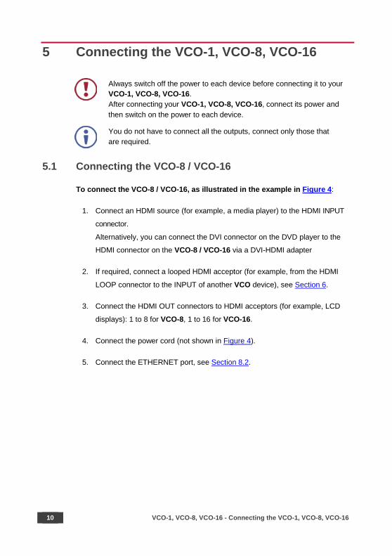
5 Connecting the VCO-1, VCO-8, VCO-16
Always switch off the power to each device before connecting it to your VCO-1, VCO-8, VCO-16. After connecting your VCO-1, VCO-8, VCO-16, connect its power and then switch on the power to each device.
You do not have to connect all the outputs, connect only those that are required.
5.1 Connecting the VCO-8 / VCO-16
To connect the VCO-8 / VCO-16, as illustrated in the example in Figure 4:
1. Connect an HDMI source (for example, a media player) to the HDMI INPUT
connector.
Alternatively, you can connect the DVI connector on the DVD player to the
HDMI connector on the VCO-8 / VCO-16 via a DVI-HDMI adapter
2. If required, connect a looped HDMI acceptor (for example, from the HDMI
LOOP connector to the INPUT of another VCO device), see Section 6.
3. Connect the HDMI OUT connectors to HDMI acceptors (for example, LCD
displays): 1 to 8 for VCO-8, 1 to 16 for VCO-16.
4. Connect the power cord (not shown in Figure 4).
5. Connect the ETHERNET port, see Section 8.2.

VCO-1, VCO-8, VCO-16 - Connecting the VCO-1, VCO-8, VCO-16 11
Figure 4: Connecting the VCO-8 / VCO-16

12 VCO-1, VCO-8, VCO-16 - Connecting the VCO-1, VCO-8, VCO-16
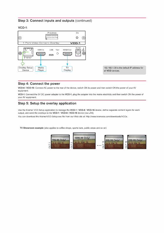
5.2 Connecting the VCO-1
To connect the VCO-1 as illustrated in the example in Figure 5:
1. Connect an HDMI source (for example, a media player) to the HDMI IN
connector.
Alternatively, you can connect the DVI connector on the DVD player to the
HDMI connector on the VCO-1 via a DVI-HDMI adapter.
2. Connect the HDMI OUT connector to an HDMI acceptor (for example, an
LCD display).
3. Connect the 5V DC power adapter to the power socket and connect the
adapter to the mains electricity (not shown in Figure 5).
4. Connect the ETHERNET port, see Section 8.2.
Figure 5: Connecting the VCO-1

VCO-1, VCO-8, VCO-16 - Looping the VCO-8 and VCO-16 13
6 Looping the VCO-8 and VCO-16
In the following example, two VCO-16 devices are connected via the LOOP
connector to produce a 32 port video overlay. One video input is distributed to 32
outputs with individual content overlay set to each of the 32 outputs.
To connect two looped VCO-16 units with 32 outputs, as shown in the example in
Figure 6, do the following:
1. On the first VCO-16 unit, connect:
A video source to the HDMI INPUT connector (for example, a Blu-ray player)
The OUT HDMI connectors to acceptors (for example, displays)
2. Connect the LOOP HDMI connector of the first unit to the INPUT HDMI
Connector of the second unit.
3. On the second VCO-16 unit, connect the OUT HDMI connectors to
acceptors (for example, LCD displays)
In the Kramer VCO Setup App, each device in the daisy chain has a separate IP address and each of the 32 outputs is given a unique name and can be set with its own specific overlay.
In the same way you can loop an almost unlimited number of devices if HDCP is
not in use and up to five devices when HDCP is in use.
When an HDCP source, such as a Blu-ray player or a SAT receiver, is used the number of looped devices may be lower.

14 VCO-1, VCO-8, VCO-16 - Looping the VCO-8 and VCO-16
Figure 6: A Set of 2 Looped VCO-16 Units

VCO-1, VCO-8, VCO-16 - Using the Kramer VCO Setup Application 15
7 Using the Kramer VCO Setup Application
Use the Kramer VCO Setup App to manage and send an overlay to each output.
The VCO Setup App allows you to take a template which can include one or more
graphic files and a playback program, modify the program and settings if needed,
and load the resulting overlay onto specific device outputs.
The graphic files can be prepared with any graphics program such as Adobe
Photoshop, Paint.NET and so on. They can include transparency, animation and for
the PSD format also editable fields.
With the playback program you can set the size and position of the overlay on the
screen and control its movement across the screen as well as its transparency
level. Each overlay playback program can be scheduled to appear at certain times
and on certain days. You can also control the frequency and rate a playback
appears.
This section describes how to:
• Install the application (see Section 7.1).
• Set the application language and add devices (see Section 7.2).
• Create an overlay and manage it (see Section 7.3).
• Create and use a schedule (see Section 7.4).
7.1 Install the VCO Setup Application
To install the VCO Setup App:
1. Download the VCO Setup App from our Website at
www.kramerav.com/downloads/VCOs
2. Open the .exe file. The following message appears:

16 VCO-1, VCO-8, VCO-16 - Using the Kramer VCO Setup Application
Figure 7: Installing the VCO Setup App - Warning
3. Click Run. The following window appears:
Figure 8: Installing the VCO Setup App – Setup Application Description
4. Click Next>.
Figure 9: Installing the VCO Setup App – Legal info

VCO-1, VCO-8, VCO-16 - Using the Kramer VCO Setup Application 17
5. Check for acceptance and click Next>.
Figure 10: Installing the VCO Setup App – Setting the Destination Folder
6. Check the destination folder and change if needed then click Install. The
software is installed:
Figure 11: Installing the VCO Setup App– Installing the Software
Figure 12: Installing the VCO Setup App – Installation is Complete

18 VCO-1, VCO-8, VCO-16 - Using the Kramer VCO Setup Application
7. Check Run Kramer VCO Setup and click Finish.
The Kramer VCO Setup App main window appears:
Figure 13: Installing the VCO Setup App – The Setup & About Tab
VCO Setup App includes three tabs:
• Setup & About – Select the application language, manage devices and read the software license agreement and description (see Section 7.2)
• Overlays – Create templates and overlays (see Section 7.3)
• Scheduling – Schedule the overlays per output (see Section 7.4)

VCO-1, VCO-8, VCO-16 - Using the Kramer VCO Setup Application 19
7.2 Setup & About
The Setup & About tab lets you set the language of the application, manage the
devices and enable control of the system via an external application.
7.2.1 Setting the Application Interface Language
To change the interface language of the application:
1. Click the Setup & About tab. The Setup & About tab appears:
Figure 14: Setup & About Tab
2. Select the application language from the dropdown box.
Figure 15: Setup & About – Selecting the Language
20 VCO-1, VCO-8, VCO-16 - Using the Kramer VCO Setup Application
3. Restart the VCO Setup App.
The interface language is changed.
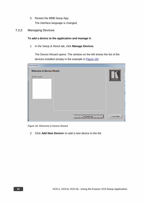
7.2.2 Managing Devices
To add a device to the application and manage it:
1. In the Setup & About tab, click Manage Devices.
The Device Wizard opens. The window on the left shows the list of the
devices installed (empty in the example in Figure 16).
Figure 16: Welcome to Device Wizard
2. Click Add New Device> to add a new device to the list.
VCO-1, VCO-8, VCO-16 - Using the Kramer VCO Setup Application 21
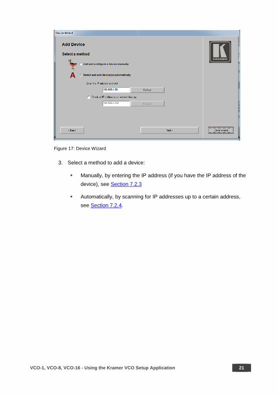
Figure 17: Device Wizard
3. Select a method to add a device:
Manually, by entering the IP address (if you have the IP address of the device), see Section 7.2.3
Automatically, by scanning for IP addresses up to a certain address, see Section 7.2.4.

22 VCO-1, VCO-8, VCO-16 - Using the Kramer VCO Setup Application
7.2.3 Add a New Device Manually
To manually add a new device to the list:
1. Check the manual option:
Figure 18: Device Wizard – Add Device Manually
2. Click Next>.
Figure 19: Device Wizard – Selecting a Device
VCO-1, VCO-8, VCO-16 - Using the Kramer VCO Setup Application 23
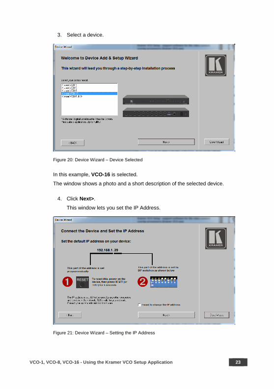
3. Select a device.
Figure 20: Device Wizard – Device Selected
In this example, VCO-16 is selected.
The window shows a photo and a short description of the selected device.
4. Click Next>.
This window lets you set the IP Address.
Figure 21: Device Wizard – Setting the IP Address

24 VCO-1, VCO-8, VCO-16 - Using the Kramer VCO Setup Application
The last part of IP address numbers is set via the DIP-switches on the rear panel of the device (see Section 8).
The first 3 (higher) parts are set via the VCO Setup application.
5. To change the IP address, check the “I want to change the IP address” box
and click Next>; otherwise click Next>.
Figure 22: Device Wizard – Setting the Lower Number of the IP address.
6. Type the lower number of the IP address and view the DIP-switch setup that
corresponds to the selected number (also see Section 8.1.1).
To change the IP address of the device requires that it is initially set to its default value.
7. To change the other parts of the IP address, check the change address box
and click Next>. If you do not want to change the other parts of the IP
address, keep that box unchecked and click Next>.
VCO-1, VCO-8, VCO-16 - Using the Kramer VCO Setup Application 25
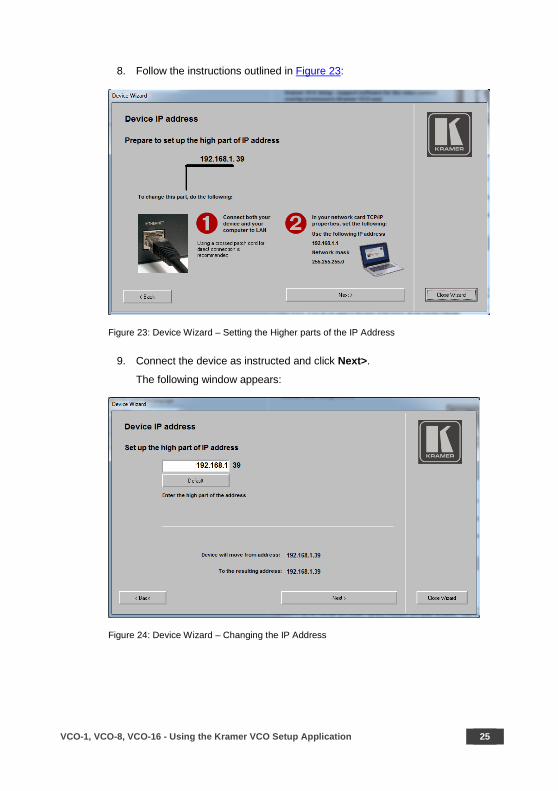
8. Follow the instructions outlined in Figure 23:
Figure 23: Device Wizard – Setting the Higher parts of the IP Address
9. Connect the device as instructed and click Next>.
The following window appears:
Figure 24: Device Wizard – Changing the IP Address

26 VCO-1, VCO-8, VCO-16 - Using the Kramer VCO Setup Application
10. Change the number, for example, to 192.168.2.39.
Figure 25: Device Wizard – Changing the Higher Parts of the IP Address
11. Click Next>. The following message appears:
Figure 26: Changing the IP Address Message
VCO-1, VCO-8, VCO-16 - Using the Kramer VCO Setup Application 27
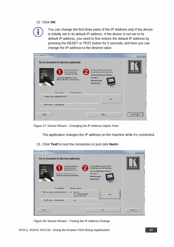
12. Click OK.
You can change the first three parts of the IP Address only if the device is initially set to its default IP address. If the device is not set to its default IP address, you need to first restore the default IP address by pressing the RESET or TEST button for 5 seconds, and then you can change the IP address to the desired value.
Figure 27: Device Wizard – Changing the IP Address Higher Parts
The application changes the IP address on the machine while it’s connected.
13. Click Test! to test the connection or just click Next>.
Figure 28: Device Wizard – Testing the IP Address Change
28 VCO-1, VCO-8, VCO-16 - Using the Kramer VCO Setup Application
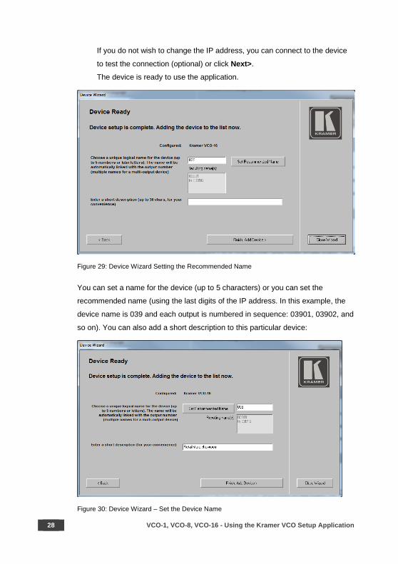
If you do not wish to change the IP address, you can connect to the device
to test the connection (optional) or click Next>.
The device is ready to use the application.
Figure 29: Device Wizard Setting the Recommended Name
You can set a name for the device (up to 5 characters) or you can set the
recommended name (using the last digits of the IP address. In this example, the
device name is 039 and each output is numbered in sequence: 03901, 03902, and
so on). You can also add a short description to this particular device:
Figure 30: Device Wizard – Set the Device Name

VCO-1, VCO-8, VCO-16 - Using the Kramer VCO Setup Application 29
14. Click Finish. Add Device>.
Figure 31: Device Wizard – Device Installed
15. Select a device to view its details:
Figure 32: Device Wizard –Device Details
In the same way you can add as many devices as required.
The final page of the wizard shows the list of the devices that were installed. You
can delete a selected device by clicking — below the list. This page shows the
properties of the selected device and lets you change each individual output name.
You can test the connection to the machine at this point.
30 VCO-1, VCO-8, VCO-16 - Using the Kramer VCO Setup Application
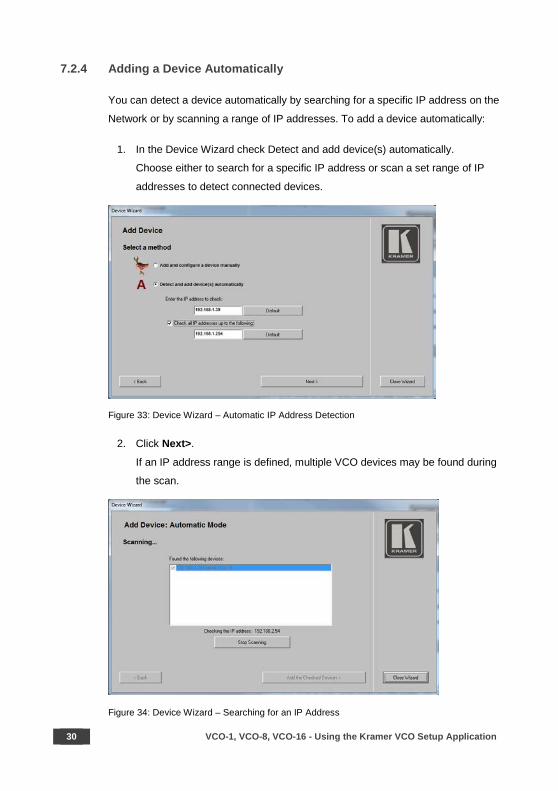
7.2.4 Adding a Device Automatically
You can detect a device automatically by searching for a specific IP address on the
Network or by scanning a range of IP addresses. To add a device automatically:
1. In the Device Wizard check Detect and add device(s) automatically.
Choose either to search for a specific IP address or scan a set range of IP
addresses to detect connected devices.
Figure 33: Device Wizard – Automatic IP Address Detection
2. Click Next>.
If an IP address range is defined, multiple VCO devices may be found during
the scan.
Figure 34: Device Wizard – Searching for an IP Address

VCO-1, VCO-8, VCO-16 - Using the Kramer VCO Setup Application 31
3. Click Stop Scanning once the expected devices are found.
Figure 35: Device Wizard – Device IP Address Detected
4. Click Add the Checked Devices>.
The selected device shows its properties and output names.
Figure 36: Device Wizard –The Device Details (following Automatic Scan)
32 VCO-1, VCO-8, VCO-16 - Using the Kramer VCO Setup Application
7.3 Setting the Overlays
The Overlay tab lets you prepare overlays to use with your VCO devices to send to
the individual outputs of the device.
You do not need to connect to a device to set the Overlays.
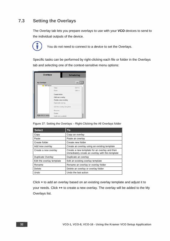
Specific tasks can be performed by right-clicking each file or folder in the Overlays
tab and selecting one of the context-sensitive menu options:
Figure 37: Setting the Overlays – Right-Clicking the All Overlays folder
Select To Copy Copy an overlay Paste Paste an overlay Create folder Create new folder Add new overlay Create an overlay using an existing template Create a new overlay Create a new template for an overlay and then
immediately create an overlay with this template Duplicate Overlay Duplicate an overlay Edit the overlay template Edit an existing overlay template Rename Rename an overlay or overlay folder Delete Delete an overlay or overlay folder Undo Undo the last action
Click + to add an overlay based on an existing overlay template and adjust it to
your needs. Click ++ to create a new overlay. The overlay will be added to the My
Overlays list.

VCO-1, VCO-8, VCO-16 - Using the Kramer VCO Setup Application 33
7.3.1 Adding an Overlay from an Existing Template
To add an overlay from a template to the My Overlays list:
1. Click the Overlays tab. The Overlay tab appears:
Figure 38: Setting the Overlays – the Overlay Tab
2. Right-click the All Overlays folder.
3. Select Create folder and type its name in the Create a new folder window
(Birthday events in this example):
Figure 39: Setting the Overlays – Create a New Folder
The new folder is added to the list:

34 VCO-1, VCO-8, VCO-16 - Using the Kramer VCO Setup Application
Figure 40: Setting the Overlays – New Folder Added
You do not need to add the new overlay to a new folder and you can just add an overlay to the main folder.
4. Click + or right-click the Birthday events folder and select Add new overlay. The following window appears:
Figure 41: Setting the Overlays – the Overlay Tab
5. In the Examples Folder select Advertisement1. The following window
shows the name of the overlay template, recommends the optimal screen
size for this template, and describes its features:

VCO-1, VCO-8, VCO-16 - Using the Kramer VCO Setup Application 35
Figure 42: Setting the Overlays – the Add New Overlay Window
You can give the overlay a new name and add a description of the overlay:
Figure 43: Setting the Overlays – Add a New Name and Description
36 VCO-1, VCO-8, VCO-16 - Using the Kramer VCO Setup Application
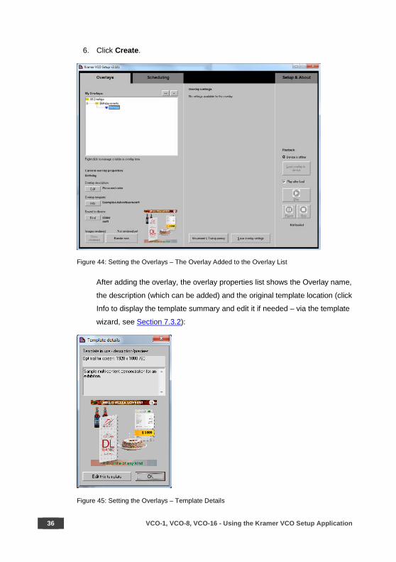
6. Click Create.
Figure 44: Setting the Overlays – The Overlay Added to the Overlay List
After adding the overlay, the overlay properties list shows the Overlay name,
the description (which can be added) and the original template location (click
Info to display the template summary and edit it if needed – via the template
wizard, see Section 7.3.2):
Figure 45: Setting the Overlays – Template Details
VCO-1, VCO-8, VCO-16 - Using the Kramer VCO Setup Application 37
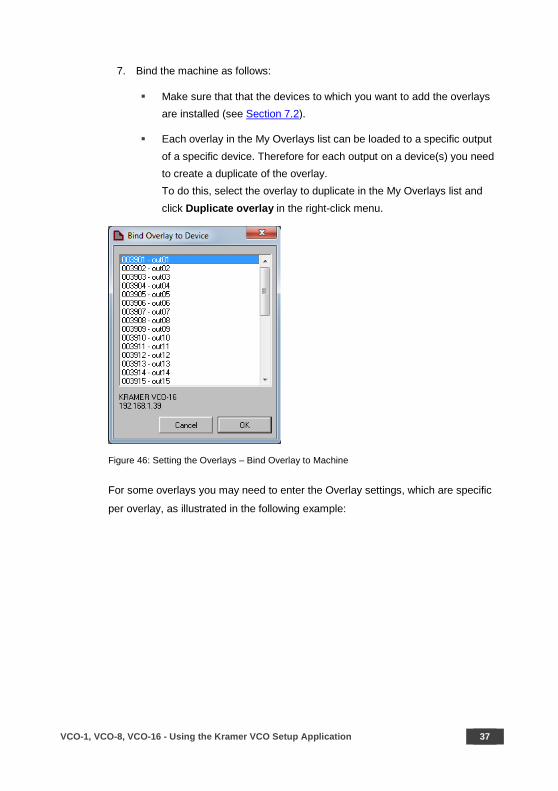
7. Bind the machine as follows:
Make sure that that the devices to which you want to add the overlays are installed (see Section 7.2).
Each overlay in the My Overlays list can be loaded to a specific output of a specific device. Therefore for each output on a device(s) you need to create a duplicate of the overlay. To do this, select the overlay to duplicate in the My Overlays list and click Duplicate overlay in the right-click menu.
Figure 46: Setting the Overlays – Bind Overlay to Machine
For some overlays you may need to enter the Overlay settings, which are specific
per overlay, as illustrated in the following example:
38 VCO-1, VCO-8, VCO-16 - Using the Kramer VCO Setup Application
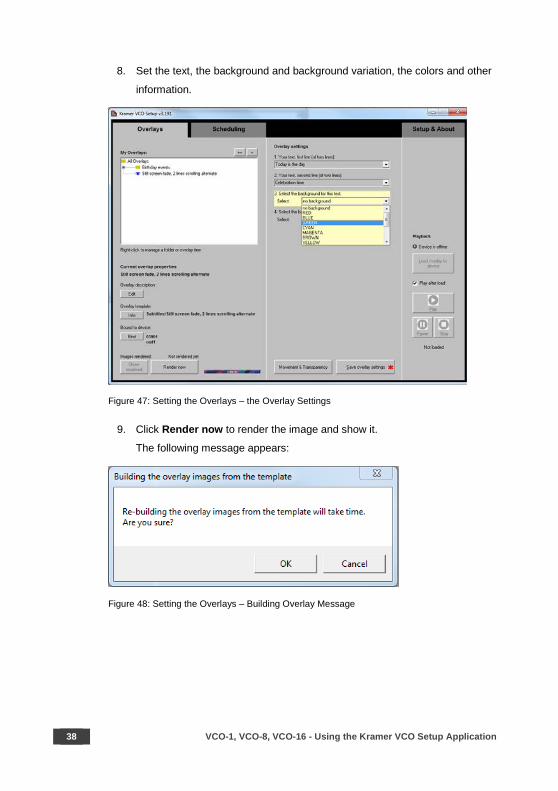
8. Set the text, the background and background variation, the colors and other
information.
Figure 47: Setting the Overlays – the Overlay Settings
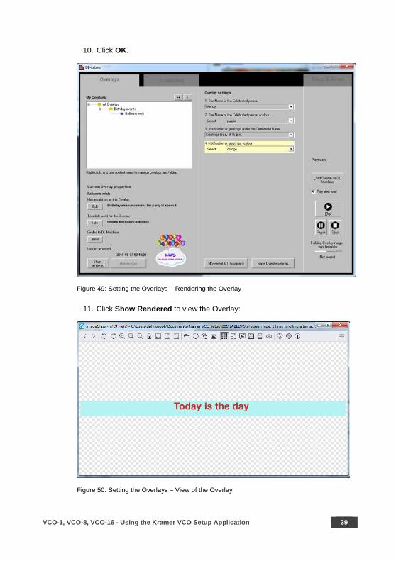
9. Click Render now to render the image and show it.
The following message appears:
Figure 48: Setting the Overlays – Building Overlay Message
VCO-1, VCO-8, VCO-16 - Using the Kramer VCO Setup Application 39
10. Click OK.
Figure 49: Setting the Overlays – Rendering the Overlay
11. Click Show Rendered to view the Overlay:
Figure 50: Setting the Overlays – View of the Overlay
40 VCO-1, VCO-8, VCO-16 - Using the Kramer VCO Setup Application
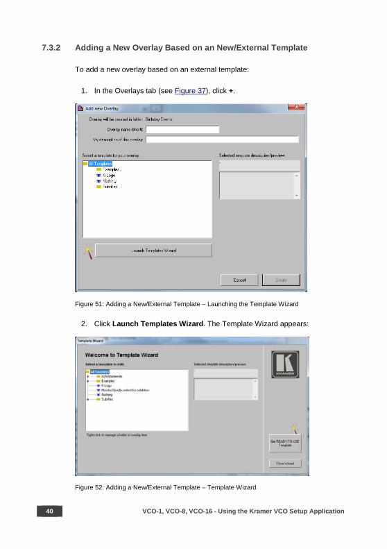
7.3.2 Adding a New Overlay Based on an New/External Template
To add a new overlay based on an external template:
1. In the Overlays tab (see Figure 37), click +.
Figure 51: Adding a New/External Template – Launching the Template Wizard
2. Click Launch Templates Wizard. The Template Wizard appears:
Figure 52: Adding a New/External Template – Template Wizard

VCO-1, VCO-8, VCO-16 - Using the Kramer VCO Setup Application 41
The template wizard lists the available templates within the application. You can
right-click a template to edit it rename or delete it. The template that is edited then
appears in its new format in the overlay template list (as in Figure 41)
Figure 53: Adding a New/External Template – Available File Operations
Right-click a template folder to create a new folder, create a new template (see
Section 7.3.3) and perform other operations.
Figure 54: Adding a New/External Template – Available Folder Operations
42 VCO-1, VCO-8, VCO-16 - Using the Kramer VCO Setup Application
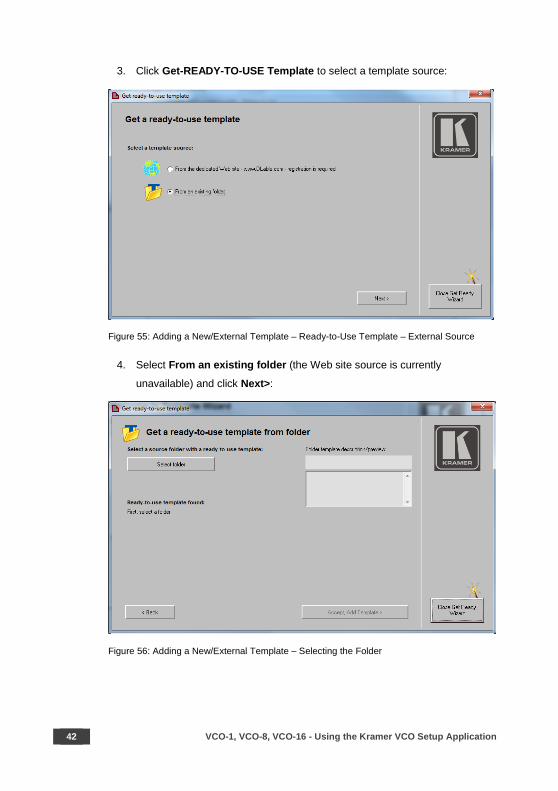
3. Click Get-READY-TO-USE Template to select a template source:
Figure 55: Adding a New/External Template – Ready-to-Use Template – External Source
4. Select From an existing folder (the Web site source is currently
unavailable) and click Next>:
Figure 56: Adding a New/External Template – Selecting the Folder
VCO-1, VCO-8, VCO-16 - Using the Kramer VCO Setup Application 43
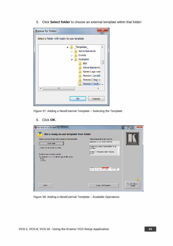
5. Click Select folder to choose an external template within that folder:
Figure 57: Adding a New/External Template – Selecting the Template
6. Click OK.
Figure 58: Adding a New/External Template – Available Operations
44 VCO-1, VCO-8, VCO-16 - Using the Kramer VCO Setup Application
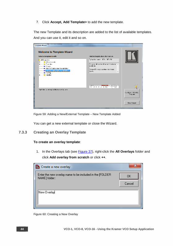
7. Click Accept, Add Template> to add the new template.
The new Template and its description are added to the list of available templates.
And you can use it, edit it and so on.
Figure 59: Adding a New/External Template – New Template Added
You can get a new external template or close the Wizard.
7.3.3 Creating an Overlay Template
To create an overlay template:
1. In the Overlays tab (see Figure 37), right-click the All Overlays folder and
click Add overlay from scratch or click ++.
Figure 60: Creating a New Overlay
VCO-1, VCO-8, VCO-16 - Using the Kramer VCO Setup Application 45
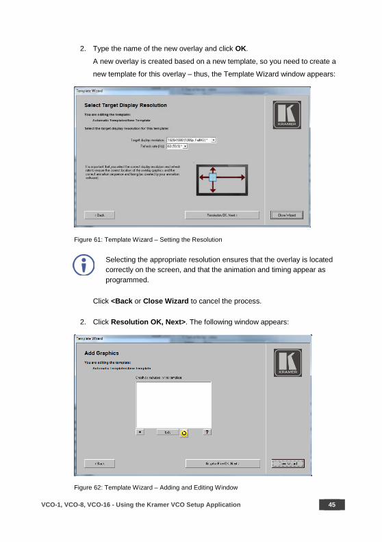
2. Type the name of the new overlay and click OK.
A new overlay is created based on a new template, so you need to create a
new template for this overlay – thus, the Template Wizard window appears:
Figure 61: Template Wizard – Setting the Resolution
Selecting the appropriate resolution ensures that the overlay is located correctly on the screen, and that the animation and timing appear as programmed.
Click <Back or Close Wizard to cancel the process.
2. Click Resolution OK, Next>. The following window appears:
Figure 62: Template Wizard – Adding and Editing Window
46 VCO-1, VCO-8, VCO-16 - Using the Kramer VCO Setup Application
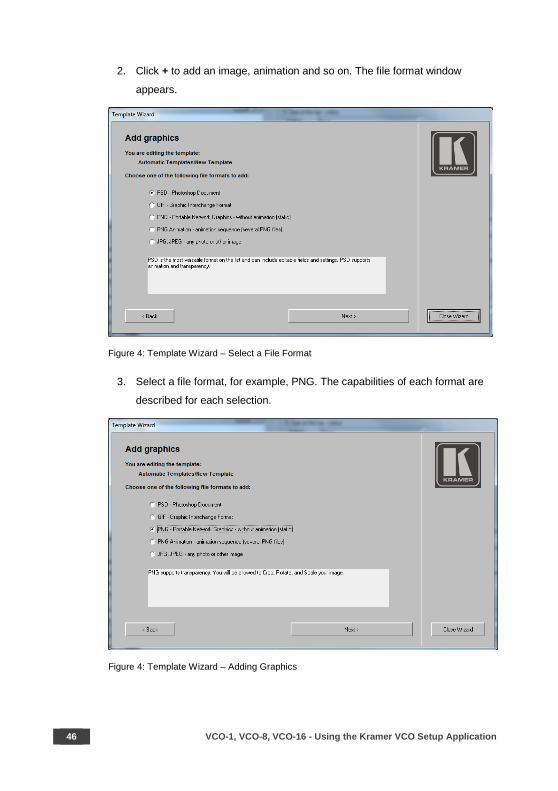
2. Click + to add an image, animation and so on. The file format window
appears.
Figure 4: Template Wizard – Select a File Format
3. Select a file format, for example, PNG. The capabilities of each format are
described for each selection.
Figure 4: Template Wizard – Adding Graphics

VCO-1, VCO-8, VCO-16 - Using the Kramer VCO Setup Application 47
4. Click Next and select a file. The selected PNG appears:
Figure 63: Template Wizard – Editing the PNG graphic
5. If required, use the Rotate and Mirror buttons to rotate and mirror the image,
respectively. Click and drag the blue markers around the image to crop the
image.
When using a JPG format, you can also set a transparent color and use
transparency. When using a PNG format, the transparency implemented in the
PNG file itself is supported (created via an external editor program).
48 VCO-1, VCO-8, VCO-16 - Using the Kramer VCO Setup Application
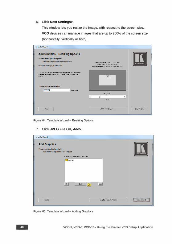
6. Click Next Settings>.
This window lets you resize the image, with respect to the screen size.
VCO devices can manage images that are up to 200% of the screen size
(horizontally, vertically or both).
Figure 64: Template Wizard – Resizing Options
7. Click JPEG File OK, Add>.
Figure 65: Template Wizard – Adding Graphics
VCO-1, VCO-8, VCO-16 - Using the Kramer VCO Setup Application 49
8. Add another file, refresh the list, edit a file (via an associated external editor)
or delete it if needed.
If there is no graphic application associated with a selected graphical format (for example, if you don’t have any editor for the PSD format), the edit button will have no effect. If you want to edit the graphic, you need to install the appropriate program.
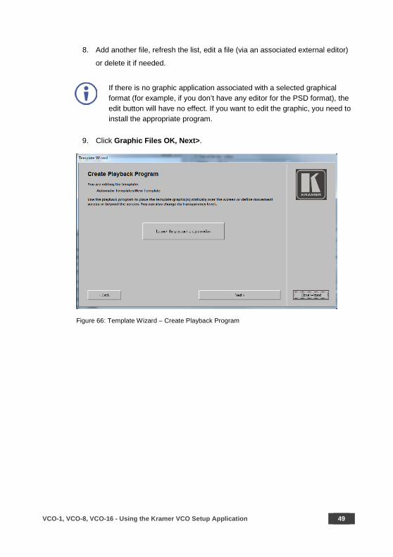
9. Click Graphic Files OK, Next>.
Figure 66: Template Wizard – Create Playback Program

50 VCO-1, VCO-8, VCO-16 - Using the Kramer VCO Setup Application
10. Click Launch the playback program editor. Set the movement and
transparency (see Section 7.3.4) and then click Next>.
Add a description of the template and view, select or edit the template
preview.
Figure 67: Template Wizard – Add Template Description and see Preview
VCO-1, VCO-8, VCO-16 - Using the Kramer VCO Setup Application 51
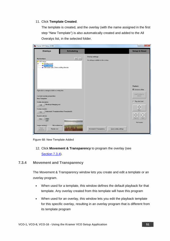
11. Click Template Created.
The template is created, and the overlay (with the name assigned in the first
step “New Template”) is also automatically created and added to the All
Overalys list, in the selected folder.
Figure 68: New Template Added
12. Click Movement & Transparency to program the overlay (see
Section 7.3.4).
7.3.4 Movement and Transparency
The Movement & Transparency window lets you create and edit a template or an
overlay program.
• When used for a template, this window defines the default playback for that template. Any overlay created from this template will have this program
• When used for an overlay, this window lets you edit the playback template for this specific overlay, resulting in an overlay program that is different from its template program

52 VCO-1, VCO-8, VCO-16 - Using the Kramer VCO Setup Application
You can create multiple overlays from a template, each with different settings and
playback programs. Once prepared, you can load these overlays to VCO devices
manually or via the scheduling feature (see Section 7.4).
The following example shows how to edit an overlay program (template program
editing is identical).
After setting the overlay, click Movement & Transparency (see Figure 49) to set
the movement and the transparency of that overlay. The Program Editor window
lets you set the movement of the overlay on the display and the transparency of
each image in the movement sequence.
Figure 69: Setting the Movement and Transparency – the Program Editor
The image files that are available for this template appear on the left side. You can
select a file from the list to add to the Program Edit window on the right side of the
window. The left lower side shows the preview of the selected image (an image is
available only after it is rendered via the Render now button, see Figure 68, or after
it is loaded to a VCO device).
VCO-1, VCO-8, VCO-16 - Using the Kramer VCO Setup Application 53
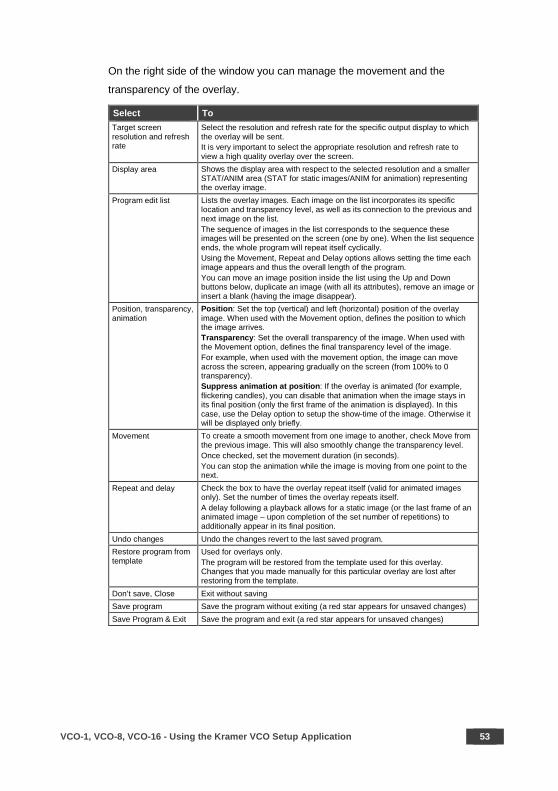
On the right side of the window you can manage the movement and the
transparency of the overlay.
Select To Target screen resolution and refresh rate
Select the resolution and refresh rate for the specific output display to which the overlay will be sent. It is very important to select the appropriate resolution and refresh rate to view a high quality overlay over the screen.
Display area Shows the display area with respect to the selected resolution and a smaller STAT/ANIM area (STAT for static images/ANIM for animation) representing the overlay image.
Program edit list Lists the overlay images. Each image on the list incorporates its specific location and transparency level, as well as its connection to the previous and next image on the list. The sequence of images in the list corresponds to the sequence these images will be presented on the screen (one by one). When the list sequence ends, the whole program will repeat itself cyclically. Using the Movement, Repeat and Delay options allows setting the time each image appears and thus the overall length of the program. You can move an image position inside the list using the Up and Down buttons below, duplicate an image (with all its attributes), remove an image or insert a blank (having the image disappear).
Position, transparency, animation
Position: Set the top (vertical) and left (horizontal) position of the overlay image. When used with the Movement option, defines the position to which the image arrives. Transparency: Set the overall transparency of the image. When used with the Movement option, defines the final transparency level of the image. For example, when used with the movement option, the image can move across the screen, appearing gradually on the screen (from 100% to 0 transparency). Suppress animation at position: If the overlay is animated (for example, flickering candles), you can disable that animation when the image stays in its final position (only the first frame of the animation is displayed). In this case, use the Delay option to setup the show-time of the image. Otherwise it will be displayed only briefly.
Movement To create a smooth movement from one image to another, check Move from the previous image. This will also smoothly change the transparency level. Once checked, set the movement duration (in seconds). You can stop the animation while the image is moving from one point to the next.
Repeat and delay Check the box to have the overlay repeat itself (valid for animated images only). Set the number of times the overlay repeats itself. A delay following a playback allows for a static image (or the last frame of an animated image – upon completion of the set number of repetitions) to additionally appear in its final position.
Undo changes Undo the changes revert to the last saved program. Restore program from template
Used for overlays only. The program will be restored from the template used for this overlay. Changes that you made manually for this particular overlay are lost after restoring from the template.
Don’t save, Close Exit without saving Save program Save the program without exiting (a red star appears for unsaved changes) Save Program & Exit Save the program and exit (a red star appears for unsaved changes)

54 VCO-1, VCO-8, VCO-16 - Using the Kramer VCO Setup Application
7.3.5 Overlay Program Example
The following example shows a sequence of four images moving across the
screen:
The image appears
below the screen
and it’s 100%
transparent:
The image moves
upwards. It appears
gradually (60%
transparency) and
moves smoothly
from the previous
point (Move from
previous image is
checked) within 2
seconds:

VCO-1, VCO-8, VCO-16 - Using the Kramer VCO Setup Application 55
The third image is
not transparent (0%)
and within 5 seconds
move from the
previous to the
current position.
The image fades out
of the screen.
56 VCO-1, VCO-8, VCO-16 - Using the Kramer VCO Setup Application
7.4 Scheduling the Overlays
Once an overlay is loaded to an output of a Kramer VCO device, it will keep playing
on that input until a different overlay is loaded to that device/output (you can
manually play, pause or stop an overlay).
The Scheduling feature lets you load overlays to devices and create playlists which
automatically load lists of overlays to one or many VCO devices. This enables the
creation of complex scenarios for multiple pre-configured overlays to load to one or
many VCO devices according to a predefined schedule.
Playlist: a playlist includes a list of events that will play according to a predefined
schedule. You can create multiple playlists. Each playlist is given a specific name.
Event: the event includes a list of overlays that can be bound to different VCO
outputs. Each event can have multiple overlays. An Event is part of a playlist and
can be scheduled and repeated as needed.
For example, a store playlist that includes two events, one for opening hours and
the other when the store is closed (they can be called Day and Night). The VCO
device includes eight outputs and all of them show the same images during
opening hours and other images for when the store is closed. Each event includes
a list of overlays that are scheduled to play at the appropriate time (this can happen
at certain days in a week, at certain time each day, and so on).
There is no limit to the number of overlays that are included in an event and to the
number of events that can be included in a playlist.
You can schedule an event after configuring the overlays and binding them to the
outputs of VCO devices. If you need an overlay to be loaded to several VCO
devices (outputs), you need to duplicate these overlays and bind them to other
devices (outputs).
We recommend that you logically create folders and subfolders in the My Overlays list for the different overlays and outputs to make it easy to navigate between duplicate overlays.

VCO-1, VCO-8, VCO-16 - Using the Kramer VCO Setup Application 57
To schedule an overlay:
1. Select the Scheduling tab. The Scheduling tab appears.
2. Click + next to My Playlists to add a new playlist name. The Playlist name
appears under My Playlists:
Figure 70: Scheduling Tab
58 VCO-1, VCO-8, VCO-16 - Using the Kramer VCO Setup Application
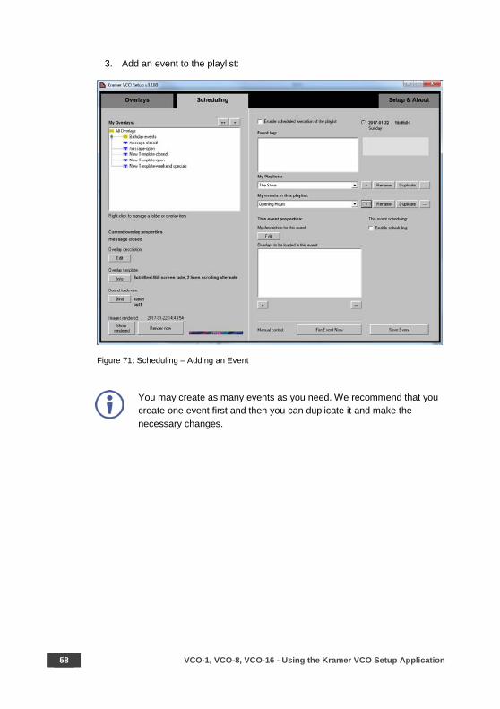
3. Add an event to the playlist:
Figure 71: Scheduling – Adding an Event
You may create as many events as you need. We recommend that you create one event first and then you can duplicate it and make the necessary changes.
VCO-1, VCO-8, VCO-16 - Using the Kramer VCO Setup Application 59
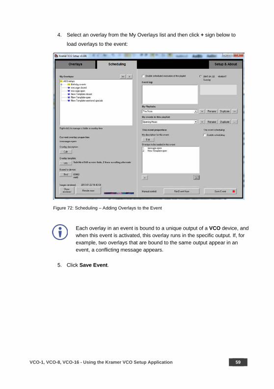
4. Select an overlay from the My Overlays list and then click + sign below to
load overlays to the event:
Figure 72: Scheduling – Adding Overlays to the Event
Each overlay in an event is bound to a unique output of a VCO device, and when this event is activated, this overlay runs in the specific output. If, for example, two overlays that are bound to the same output appear in an event, a conflicting message appears.
5. Click Save Event.

60 VCO-1, VCO-8, VCO-16 - Using the Kramer VCO Setup Application
6. Click Fire Event Now to make sure that the event list is OK.
Figure 73: Scheduling – Firing an Event
You can also use fire event just to load a number of overlays with one click.
VCO-1, VCO-8, VCO-16 - Using the Kramer VCO Setup Application 61
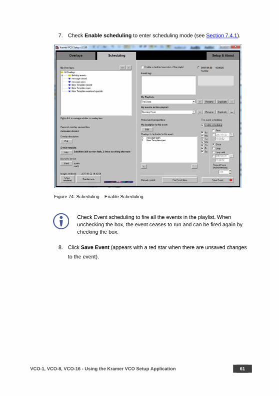
7. Check Enable scheduling to enter scheduling mode (see Section 7.4.1).
Figure 74: Scheduling – Enable Scheduling
Check Event scheduling to fire all the events in the playlist. When unchecking the box, the event ceases to run and can be fired again by checking the box.
8. Click Save Event (appears with a red star when there are unsaved changes
to the event).

62 VCO-1, VCO-8, VCO-16 - Using the Kramer VCO Setup Application
7.4.1 Scheduling Modes
Each event in the playlist can be set to a different mode. The following table defines
the available scheduling modes:
Selecting the days of a week
Applies to all scheduling modes.
To set: check the days of the week for the event to fire.
Your event will fire only at the day of the week that is checked. Uncheck a weekday to prevent firing of an event on that day.
Once, when scheduling mode starts
The event fires once when scheduling mode
starts (that is when you check the Enable
scheduling execution option).
To set: select Once and uncheck From.
Recommended use: when initializing VCO devices with some default overlays, when the
whole system starts. For example, for such an
event you may configure overlays based on the
“Nothing” template (see Figure 41); this
configuration will remove any overlay from the
VCO devices.
VCO-1, VCO-8, VCO-16 - Using the Kramer VCO Setup Application 63
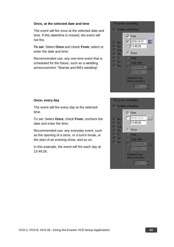
Once, at the selected date and time
The event will fire once at the selected date and time. If this date/time is missed, the event will not fire.
To set: Select Once and check From; select or enter the date and time.
Recommended use: any one-time event that is scheduled for the future, such as a wedding announcement: “Wanda and Bill’s wedding”.
Once, every day
The event will fire every day at the selected time.
To set: Select Once, check From, uncheck the date and enter the time.
Recommended use: any everyday event, such as the opening of a store, or a lunch break, or the start of an evening show, and so on.
In this example, the event will fire each day at 13:49:26.

64 VCO-1, VCO-8, VCO-16 - Using the Kramer VCO Setup Application
Repeat, since scheduling is started
The event will fire when scheduling mode is started, and then will repeat with a selected period.
To set: Select Loop, uncheck From, enter the firing rate in Repeat Every.
Recommended use: any repeated event, for which a start time or date are not important. This mode is rarely used, as in most cases such an event can interfere with other, more deterministic events in the system.
In this example, the event will fire every 1 hour and 20 minutes.
Repeat, from a selected date and time
The event will fire at the selected date and time, and then will repeat at a certain rate. If the selected date was missed, the event will start firing at the selected time of the nearest possible day. Every other day, the event will re-synchronize itself with the selected time.
This means that, if the selected start time will arrive before the time of firing according to the repeat rate, then the event will fire at the selected time, and the repetitions will re-start from that time.
To set: Select Loop; check From; select or enter date; enter time; enter period in Repeat Every.
Recommended use: any repeated event with no stop time limit. For example, you may interweave this event and another repeated event. Just set these events to different start times (for example, set the first event to 8:00 and the other to 8:30). Set both events to the same repeat rate (1 hour, for example). This will result in altering the overlays from one to another every 30 minutes.
VCO-1, VCO-8, VCO-16 - Using the Kramer VCO Setup Application 65
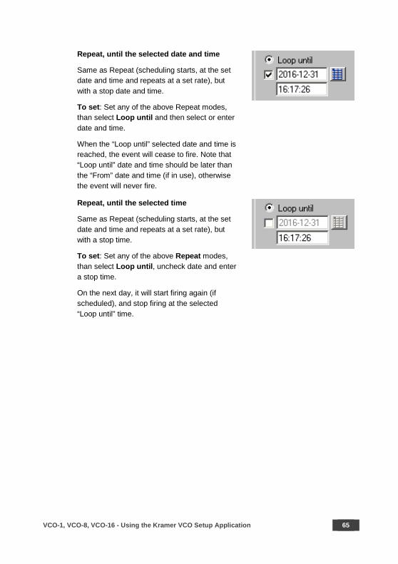
Repeat, until the selected date and time
Same as Repeat (scheduling starts, at the set date and time and repeats at a set rate), but with a stop date and time.
To set: Set any of the above Repeat modes, than select Loop until and then select or enter date and time.
When the “Loop until” selected date and time is reached, the event will cease to fire. Note that “Loop until” date and time should be later than the “From” date and time (if in use), otherwise the event will never fire.
Repeat, until the selected time
Same as Repeat (scheduling starts, at the set date and time and repeats at a set rate), but with a stop time.
To set: Set any of the above Repeat modes, than select Loop until, uncheck date and enter a stop time.
On the next day, it will start firing again (if scheduled), and stop firing at the selected “Loop until” time.

66 VCO-1, VCO-8, VCO-16 - Defining an IP Address for a Device
8 Defining an IP Address for a Device
When a static IP address is used, the first three numbers of the address are defined
via the labeling software and the fourth number is set by the DIP-switches on the
rear panel of the machine (see Figure 75). This is very useful when setting labels
for large systems.
Figure 75: Setting the IP Address
8.1 Setting a Static IP Address
The first three IP numbers are set via VCO Setup Application Machine Wizard (see
Section 7.2.3), or via K-Upload (see Section 8.1.2) and the last number is set by the
DIP-switches (see Section 8.1.1). You can also set the DHCP mode (see
Section 8.1.3)
8.1.1 Using the DIP-Switches
The last IP number is set by the DIP-switches at the rear of the machine (in binary
code, 8 bits). Use 8-bit binary code for this number (DIP#1 is LSB, DIP#8 is MSB).
Valid numbers are 1 to 254 (default factory setting is 39).
The following are examples of IP address setups of the last number of the IP
address (192.168.1.XXX):

VCO-1, VCO-8, VCO-16 - Defining an IP Address for a Device 67
IP Address (192.168.1.XXX) DIP-Switch Setup (1=On; 0=Off) 39
1 1 1 0 0 1 0 0
40
0 0 0 1 0 1 0 0
41
1 0 0 1 0 1 0 0
42
0 1 0 1 0 1 0 0
43
1 1 0 1 0 1 0 0
44
0 0 1 1 0 1 0 0
45
1 0 1 1 0 1 0 0
46
0 1 1 1 0 1 0 0
47
1 1 1 1 0 1 0 0
48
0 0 0 0 1 1 0 0
49
1 0 0 0 1 1 0 0
50
0 1 0 0 1 1 0 0
68 VCO-1, VCO-8, VCO-16 - Defining an IP Address for a Device
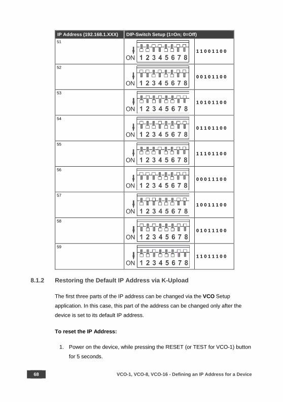
IP Address (192.168.1.XXX) DIP-Switch Setup (1=On; 0=Off) 51
1 1 0 0 1 1 0 0
52
0 0 1 0 1 1 0 0
53
1 0 1 0 1 1 0 0
54
0 1 1 0 1 1 0 0
55
1 1 1 0 1 1 0 0
56
0 0 0 1 1 1 0 0
57
1 0 0 1 1 1 0 0
58
0 1 0 1 1 1 0 0
59
1 1 0 1 1 1 0 0
8.1.2 Restoring the Default IP Address via K-Upload
The first three parts of the IP address can be changed via the VCO Setup
application. In this case, this part of the address can be changed only after the
device is set to its default IP address.
To reset the IP Address:
1. Power on the device, while pressing the RESET (or TEST for VCO-1) button
for 5 seconds.
VCO-1, VCO-8, VCO-16 - Defining an IP Address for a Device 69
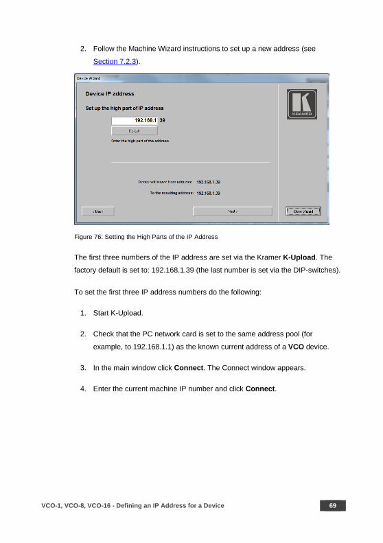
2. Follow the Machine Wizard instructions to set up a new address (see
Section 7.2.3).
Figure 76: Setting the High Parts of the IP Address
The first three numbers of the IP address are set via the Kramer K-Upload. The
factory default is set to: 192.168.1.39 (the last number is set via the DIP-switches).
To set the first three IP address numbers do the following:
1. Start K-Upload.
2. Check that the PC network card is set to the same address pool (for
example, to 192.168.1.1) as the known current address of a VCO device.
3. In the main window click Connect. The Connect window appears.
4. Enter the current machine IP number and click Connect.

70 VCO-1, VCO-8, VCO-16 - Defining an IP Address for a Device
5. In the Device Properties area change the first three numbers of the IP
address (you do not need to change the fourth number as it is set via the
DIP-switches).
Note that you might also need to change the Gateway and Mask.
6. Click Save.
The first three numbers of the IP address are saved.
8.1.3 The DHCP Mode
Some LAN networks may require the use of DHCP mode for the machine. In the
DHCP mode, a DHCP server will assign all IP settings to your machine. To set the
machine to the DHCP mode set the DIP-switches on the machine to OFF:
0 0 0 0 0 0 0 0
Figure 77: DHCP Mode DIP-Switch Setup
The machine can be identified in the network via its MAC address (which is printed
on the label that is attached to the underside of the machine), and by the network
name (“KRAMER_xxxxxx”, with xxxxxx representing the last 6 hexadecimal digits of
the MAC address of this device).
8.2 Operating via the Ethernet
You can connect to the VCO-1, VCO-8, VCO-16 via Ethernet using either of the
following methods:
• Directly to the PC using a crossover cable (see Section 8.2.1)
• Via a network hub, switch, or router, using a straight-through cable (see Section 8.2.2)
Note: If you want to connect via a router and your IT system is based on IPv6,
speak to your IT department for specific installation instructions.

VCO-1, VCO-8, VCO-16 - Defining an IP Address for a Device 71
8.2.1 Connecting the Ethernet Port Directly to a PC
You can connect the Ethernet port of the VCO-1, VCO-8, VCO-16 directly to the
Ethernet port on your PC using a crossover cable with RJ-45 connectors.
This type of connection is recommended for identifying the VCO-1, VCO-8, VCO-16 with the factory configured default IP address.
After connecting the VCO-1, VCO-8, VCO-16 to the Ethernet port, configure your
PC as follows:
1. Click Start > Control Panel > Network and Sharing Center.
2. Click Change Adapter Settings.
3. Highlight the network adapter you want to use to connect to the device and
click Change settings of this connection.
The Local Area Connection Properties window for the selected network
adapter appears as shown in Figure 78.

72 VCO-1, VCO-8, VCO-16 - Defining an IP Address for a Device
Figure 78: Local Area Connection Properties Window
4. Highlight either Internet Protocol Version 6 (TCP/IPv6) or Internet
Protocol Version 4 (TCP/IPv4) depending on the requirements of your IT
system.
5. Click Properties.
The Internet Protocol Properties window relevant to your IT system appears
as shown in Figure 79 or Figure 80.
Figure 79: Internet Protocol Version 4 Properties Window
VCO-1, VCO-8, VCO-16 - Defining an IP Address for a Device 73
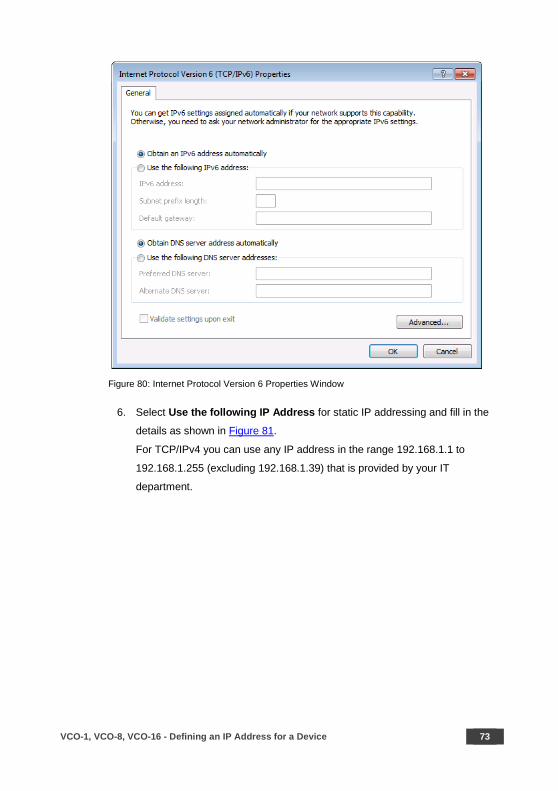
Figure 80: Internet Protocol Version 6 Properties Window
6. Select Use the following IP Address for static IP addressing and fill in the
details as shown in Figure 81.
For TCP/IPv4 you can use any IP address in the range 192.168.1.1 to
192.168.1.255 (excluding 192.168.1.39) that is provided by your IT
department.

74 VCO-1, VCO-8, VCO-16 - Defining an IP Address for a Device
Figure 81: Internet Protocol Properties Window
7. Click OK.
8. Click Close.
8.2.2 Connecting the Ethernet Port via a Network Hub or Switch
You can connect the Ethernet port of the VCO-1, VCO-8, VCO-16 to the Ethernet
port on a network hub or using a straight-through cable with RJ-45 connectors.

VCO-1, VCO-8, VCO-16 - Technical Specifications 75
9 Technical Specifications
Inputs: VCO-1, VCO-8, VCO-16: 1 HDMI connector (HDMI, HDCP version 1.4), 1 USB port
Outputs: VCO-1: 1 HDMI connector (HDMI, HDCP version 1.4) VCO-8: 8 HDMI connectors (HDMI, HDCP version 1.4), 1 LOOP HDMI connector VCO-16: 16 HDMI connectors (HDMI, HDCP version 1.4), 1 LOOP HDMI connector
Ports VCO-1, VCO-8, VCO-16: 1 RJ-45 Ethernet port 10/100BaseT Bandwidth: Full HD resolution (1080p60 or 1920x1200) Controls IP address setup DIP-switches, Reset/Test button, Ethernet (VCO
Setup App), output status indication LEDs, input indication LED, loop indication LED (for VCO-8 and VCO-16 only)
Power Consumption: VCO-1: 5V DC, 800mA max. VCO-8: 100-240V AC, 32VA max. VCO-16: 100-240V AC, 32VA max.
Operating Temperature: 0° to +40°C (32° to 104°F) Storage Temperature: -40° to +70°C (-40° to 158°F) Humidity: 10% to 90%, RHL non-condensing Dimensions: VCO-1: 12cm x 7.1cm x 2.4cm (4.7" x 2.8" x 0.94") W, D, H
VCO-8, VCO-16: 19" x 7" x 1U (W, D, H) rack mountable Shipping Dimensions: VCO-1: 15.7cm x 12cm x 8.7cm (6.2" x 4.7" x 3.4") W, D, H
VCO-8, VCO-16: 55cm x 27.6cm x 10.7cm (21.6" x 10.9" x 4.2") W, D, H
Weight: VCO-1: 0.25kg (0.55lbs) approx. VCO-8: 1.53kg (3.37lbs) approx. VCO-16: 1.7kg (3.74lbs) approx.
Shipping Weight: VCO-1: 0.66kg (1.45lbs) approx. VCO-8: 2.42kg (5.3lbs) approx. VCO-16: 2.6kg (5.7lbs) approx.
Included Accessories: VCO-1: Power supply unit (5V DC, 4A) VCO-8, VCO-16: Power cord, rack ears, cable bracket, cable plastic ties
VCO-1: RK-3T 19” rack mount Specifications are subject to change without notice. For the most updated specifications, go to our Web site at www.kramerav.com

76 VCO-1, VCO-8, VCO-16 - Technical Specifications
9.1 Default Communication Parameters
Ethernet
IP Address: 192.168.1.39 Subnet mask: 255.255.255.0 Default gateway: 192.168.1.254 TCP Port #: 5000
Full Factory Reset
Reset/Test button While power is switched on, press and hold the RESET (or TEST) button for at least 5 seconds. Set the DIP-switches to 1 1 1 0 0 1 0 0 positions (DIP#1 to DIP#8, 1=on, 0=off).
Ethernet (TCP/IP) Command Protocol
Command Format: ASCII protocol 3000 Example (Stop playback, and remove overlay from the screen for output 1):
#Y 0,150,0,0<CR>
VCO-1, VCO-8, VCO-16 - Communication Protocol 77
10 Communication Protocol
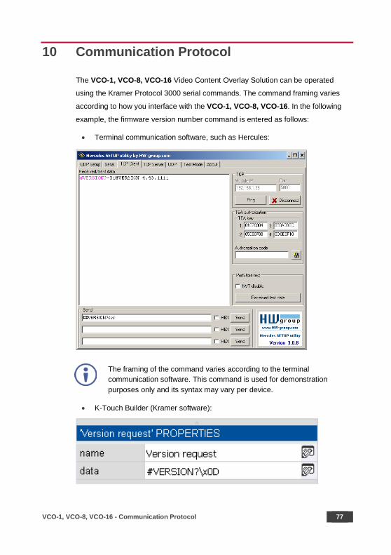
The VCO-1, VCO-8, VCO-16 Video Content Overlay Solution can be operated
using the Kramer Protocol 3000 serial commands. The command framing varies
according to how you interface with the VCO-1, VCO-8, VCO-16. In the following
example, the firmware version number command is entered as follows:
• Terminal communication software, such as Hercules:
The framing of the command varies according to the terminal communication software. This command is used for demonstration purposes only and its syntax may vary per device.
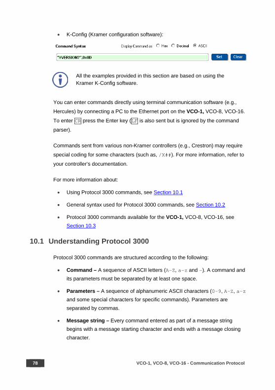
• K-Touch Builder (Kramer software):
78 VCO-1, VCO-8, VCO-16 - Communication Protocol
• K-Config (Kramer configuration software):
All the examples provided in this section are based on using the Kramer K-Config software.
You can enter commands directly using terminal communication software (e.g.,
Hercules) by connecting a PC to the Ethernet port on the VCO-1, VCO-8, VCO-16.
To enter CR press the Enter key (LF is also sent but is ignored by the command
parser).
Commands sent from various non-Kramer controllers (e.g., Crestron) may require
special coding for some characters (such as, /X##). For more information, refer to
your controller’s documentation.
For more information about:
• Using Protocol 3000 commands, see Section 10.1
• General syntax used for Protocol 3000 commands, see Section 10.2
• Protocol 3000 commands available for the VCO-1, VCO-8, VCO-16, see Section 10.3
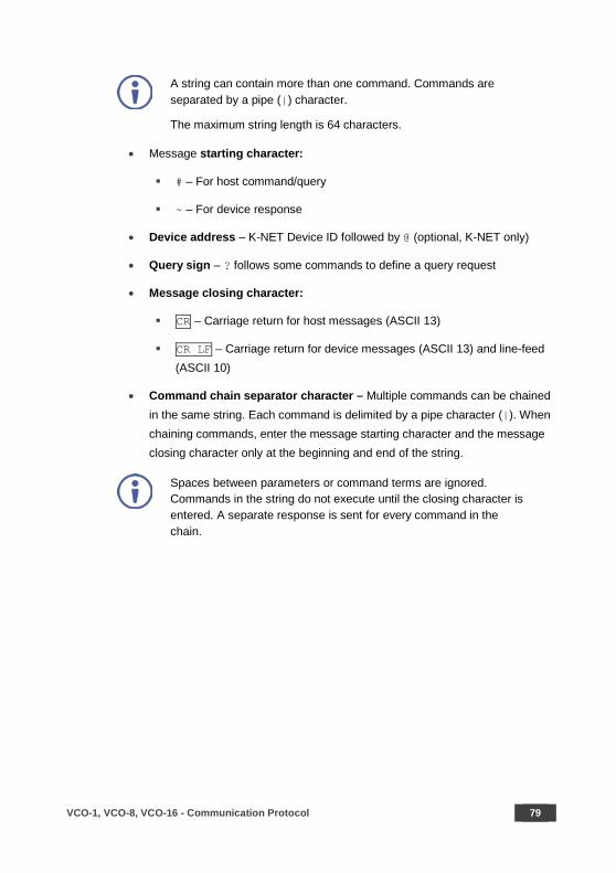
10.1 Understanding Protocol 3000
Protocol 3000 commands are structured according to the following:
• Command – A sequence of ASCII letters (A-Z, a-z and -). A command and its parameters must be separated by at least one space.
• Parameters – A sequence of alphanumeric ASCII characters (0-9, A-Z, a-z and some special characters for specific commands). Parameters are separated by commas.
• Message string – Every command entered as part of a message string begins with a message starting character and ends with a message closing character.
VCO-1, VCO-8, VCO-16 - Communication Protocol 79
A string can contain more than one command. Commands are separated by a pipe (|) character.
The maximum string length is 64 characters.
• Message starting character:
# – For host command/query
~ – For device response
• Device address – K-NET Device ID followed by @ (optional, K-NET only)
• Query sign – ? follows some commands to define a query request
• Message closing character:
CR – Carriage return for host messages (ASCII 13)
CR LF – Carriage return for device messages (ASCII 13) and line-feed (ASCII 10)
• Command chain separator character – Multiple commands can be chained in the same string. Each command is delimited by a pipe character (|). When chaining commands, enter the message starting character and the message closing character only at the beginning and end of the string.
Spaces between parameters or command terms are ignored. Commands in the string do not execute until the closing character is entered. A separate response is sent for every command in the chain.

80 VCO-1, VCO-8, VCO-16 - Communication Protocol
10.2 Kramer Protocol 3000 Syntax
The Kramer Protocol 3000 syntax uses the following delimiters:
• CR = Carriage return (ASCII 13 = 0x0D)
• LF = Line feed (ASCII 10 = 0x0A)
• SP = Space (ASCII 32 = 0x20)
Some commands have short name syntax in addition to long name syntax to
enable faster typing. The response is always in long syntax.
The Protocol 3000 syntax is in the following format:
• Host Message Format:
Start Address (optional) Body Delimiter # Device_id@ Message CR
• Simple Command – Command string with only one command without addressing:
Start Body Delimiter # Command SP Parameter_1,Parameter_2,… CR
• Command String – Formal syntax with command concatenation and addressing:
Start Address Body Delimiter # Device_id@ Command_1 Parameter1_1,Parameter1_2,…|
Command_2 Parameter2_1,Parameter2_2,…| Command_3 Parameter3_1,Parameter3_2,…|…
CR
• Device Message Format: Start Address (optional) Body Delimiter ~ Device_id@ Message CR LF
• Device Long Response – Echoing command:
Start Address (optional) Body Delimiter ~ Device_id@ Command SP [Param1,Param2 …] result CR LF
VCO-1, VCO-8, VCO-16 - Communication Protocol 81
10.3 Protocol 3000 Commands
This section includes the following commands:
• System commands (see Section 10.3.1)
• Communication commands (see Section 10.3.2)
• Device-specific P3000 commands (see Section 10.3.3)
• Device-specific Y commands (see Section 10.3.4)
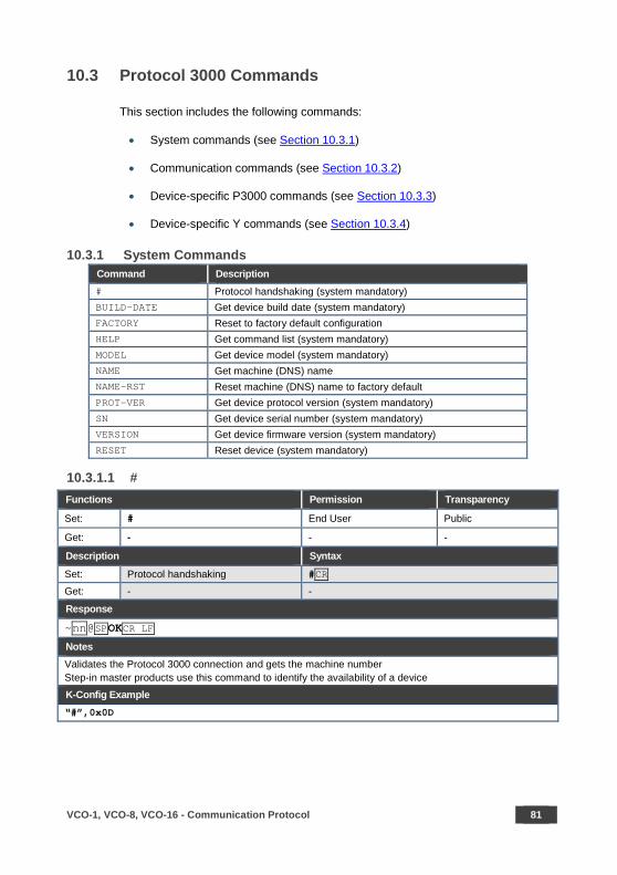
10.3.1 System Commands Command Description # Protocol handshaking (system mandatory) BUILD-DATE Get device build date (system mandatory) FACTORY Reset to factory default configuration HELP Get command list (system mandatory) MODEL Get device model (system mandatory) NAME Get machine (DNS) name NAME-RST Reset machine (DNS) name to factory default PROT-VER Get device protocol version (system mandatory) SN Get device serial number (system mandatory) VERSION Get device firmware version (system mandatory) RESET Reset device (system mandatory)
10.3.1.1 # Functions Permission Transparency
Set: # End User Public
Get: - - -
Description Syntax
Set: Protocol handshaking #CR
Get: - -
Response
~nn@SPOKCR LF
Notes Validates the Protocol 3000 connection and gets the machine number Step-in master products use this command to identify the availability of a device
K-Config Example “#”,0x0D

82 VCO-1, VCO-8, VCO-16 - Communication Protocol
10.3.1.1 BUILD-DATE Functions Permission Transparency Set: BUILD-DATE End User - Get: - - -
Description Syntax Set: Get: get device build date #BUILD-DATE?CR
Response ~nn@BUILD-DATESPdateSPtimeCR LF Parameters date – Format: YYYY/MM/DD where YYYY = Year, MM = Month, DD = Day time – Format: hh:mm:ss where hh = hours, mm = minutes, ss = seconds K-Config Example Read the device build date: “#BUILD-DATE?”,0x0D
10.3.1.1 FACTORY Functions Permission Transparency Set: FACTORY End User Public Get: - - -
Description Syntax Set: Reset device to factory defaults configuration #FACTORYCR Get: - -
Response
~nn@FACTORYSPOKCR LF Notes This command deletes all user data from the device. The deletion can take some time. Your device may require powering off and powering on for the changes to take effect. K-Config Example Reset the device to its factory default configuration: “#FACTORY”,0x0D
VCO-1, VCO-8, VCO-16 - Communication Protocol 83
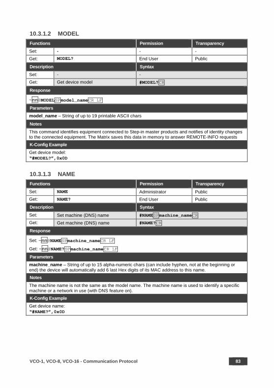
10.3.1.2 MODEL Functions Permission Transparency Set: - - - Get: MODEL? End User Public
Description Syntax Set: - - Get: Get device model #MODEL?CR
Response
~nn@MODELSPmodel_nameCR LF
Parameters model_name – String of up to 19 printable ASCII chars
Notes This command identifies equipment connected to Step-in master products and notifies of identity changes to the connected equipment. The Matrix saves this data in memory to answer REMOTE-INFO requests
K-Config Example Get device model: “#MODEL?”,0x0D
10.3.1.3 NAME Functions Permission Transparency Set: NAME Administrator Public Get: NAME? End User Public
Description Syntax Set: Set machine (DNS) name #NAMESPmachine_nameCR Get: Get machine (DNS) name #NAME?CR
Response
Set: ~nn@NAMESPmachine_nameCR LF
Get: ~nn@NAME?SPmachine_nameCR LF
Parameters machine_name – String of up to 15 alpha-numeric chars (can include hyphen, not at the beginning or end) the device will automatically add 6 last Hex digits of its MAC address to this name.
Notes The machine name is not the same as the model name. The machine name is used to identify a specific machine or a network in use (with DNS feature on).
K-Config Example Get device name: “#NAME?”,0x0D

84 VCO-1, VCO-8, VCO-16 - Communication Protocol
10.3.1.4 NAME-RST Functions Permission Transparency Set: - Administrator Public Get: NAME-RST - -
Description Syntax Set: Reset machine (DNS) name to
factory default #NAME-RSTCR
Get:
Response
~nn@NAME-RSTSPOKCR LF
Notes Factory default of machine (DNS) name is “KRAMER_” + 4 last digits of device serial number.
K-Config Example Reset device name: “#NAME-RST”,0x0D
10.3.1.5 PROT-VER Functions Permission Transparency Set: - - - Get: PROT-VER? End User Public
Description Syntax Set: - - Get: Get protocol version #PROT-VER?CR
Response
~nn@PROT-VERSP3000:versionCR LF
Parameters Version – Format: XX.XX where X is a decimal digit
K-Config Example Get the protocol version: “#PROT-VER?”,0x0D

VCO-1, VCO-8, VCO-16 - Communication Protocol 85
10.3.1.6 SN Functions Permission Transparency
Set: - - - Get: SN? End User Public
Description Syntax
Set: - -
Get: Get device serial number #SN?CR
Response
~nn@SNSPserial_numberCR LF
Parameters serial_number – 14 decimal digits, factory assigned
K-Config Example Get device serial number: “#SN?”,0x0D
10.3.1.7 VERSION Functions Permission Transparency Set: - - -
Get: VERSION? End User Public
Description Syntax Set: - - Get: Get version number #VERSION?CR
Response
~nn@VERSIONSPfirmware_versionCR LF
Parameters firmware_version – Format: XX.XX.XXXX where the digits group are: major.minor.build version
K-Config Example Get the firmware version number: “#VERSION?”,0x0D
10.3.1.8 RESET Functions Permission Transparency
Set: RESET Administrator Public Get: - - -
Description Syntax
Set: Reset device #RESETCR Get: - -
Response
~nn@RESETSPOKCR LF K-Config Example
Reset the device: “#RESET?”,0x0D
86 VCO-1, VCO-8, VCO-16 - Communication Protocol
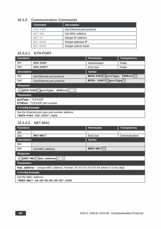
10.3.2 Communication Commands Command Description ETH-PORT Get Ethernet port protocol NET-MAC Get MAC address NET-IP Set/get IP address NET-GATE Set/get gateway IP NET-MASK Set/get subnet mask
10.3.2.1 ETH-PORT Functions Permission Transparency Set: ETH-PORT Administrator Public Get: ETH-PORT? End User Public
Description Syntax Set: Set Ethernet port protocol #ETH-PORTSPportType, ETHPortCR
Get: Get Ethernet port protocol #ETH- PORT?SPportTypeCR
Response
~nn@ETH-PORTSPportType, ETHPortCR LF
Parameters portType – TCP/UDP ETHPort - TCP/UDP port number K-Config Example Set the Ethernet port type and number address: “#ETH-PORT TCP,5000”,0x0D
10.3.2.2 NET-MAC Functions Permission Transparency Set: - - - Get: NET-MAC? End User Communication Description Syntax Set: Get: Get MAC address #NET-MAC?CR
Response
~nn@NET-MACSPmac_addressCR LF
Parameters mac_address – Unique MAC address. Format: XX-XX-XX-XX-XX-XX where X is hex digit.
K-Config Example Get the MAC address: “#NET-MAC? XX-XX-XX-XX-XX-XX”,0x0D

VCO-1, VCO-8, VCO-16 - Communication Protocol 87
10.3.2.3 NET IP Functions Permission Transparency Set: NET-IP Administrator - Get: NET-IP? End User Communication
Description Syntax Set: Set device IP address #NET-IPSPP1CR Get: Get device IP address #NET-IP?CR
Response
Set: ~nn@NET-IPSPip_addressSPOK CRLF Get: ~nn@NET-IPSPip_addressCR LF
Parameters
P1 – IP address, in the following format: xxx.xxx.xxx.xxx (since the last xxx number is set by the DIP-switches, it is ignored in this command)
Notes For proper settings consult your network administrator.
K-Config Example Set the IP address to 192.168.1.39: “#NET-IP 192.168.001.039”,0x0D
10.3.2.4 NET-GATE Functions Permission Transparency Set: NET-GATE Administrator -
Get: NET-GATE? End User Communication Description Syntax Set: Set Gateway IP #NET-GATESPP1CR Get: Get Gateway IP #NET-GATE?CR Response
Set: ~nn@NET-GATESP P1SPOKCR LF
Get: ~nn@NET-GATESPip_address CR LF
Parameters P1 – gateway IP address, in the following format:
Notes A network gateway connects the device via another network and maybe over the Internet. Be careful of security problems. For proper settings consult your network administrator
K-Config Example Set the gateway IP address to 192.168.0.1: “#NET-GATE 192.168.000.001”,0x0D
88 VCO-1, VCO-8, VCO-16 - Communication Protocol
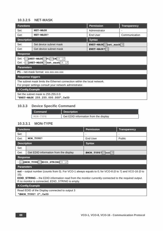
10.3.2.5 NET-MASK Functions Permission Transparency Set: NET-MASK Administrator - Get: NET-MASK? End User Communication
Description Syntax Set: Set device subnet mask #NET-MASKSPnet_maskCR Get: Get device subnet mask #NET-MASK?CR
Response
Set: ~nn@NET-MASKSPP1SPOKCR LF Get: ~nn@NET-MASKSPnet_maskCR LF
Parameters P1 – net-mask format: xxx.xxx.xxx.xxx
Response triggers The subnet mask limits the Ethernet connection within the local network. For proper settings consult your network administrator. K-Config Example Set the subnet mask to 255.255.0.0: “#NET-MASK 255.255.000.000”,0x0D
10.3.3 Device Specific Command Command Description MON-TYPE Get EDID information from the display
10.3.3.1 MON-TYPE Functions Permission Transparency Set: - - Get: MON_TYPE? End User Public
Description Syntax Set:
Get: Get EDID information from the display #MON_TYPE?SPoutCR
Response ~ nn@MON_TYPESPEDID_STRINGCR LF Parameters out – output number (counts from 0). For VCO-1 always equals to 0; for VCO-8 (0 to 7) and VCO-16 (0 to 15). EDID_STRING – the EDID information read from the monitor currently connected to the required output. If no monitor is connected, EDID_STRING is empty. K-Config Example Read EDID of the Display connected to output 3 “#MON_TYPE? 2”,0x0D

VCO-1, VCO-8, VCO-16 - Communication Protocol 89
10.3.4 Device-Specific “Y” Commands
Syntax for a “set” command (write value to the device):
#Y 0,function,value,parameter<CR>
Device response:
#Y 0,function,value,parameter<CR>
Syntax for a “get” command (read value from the device):
#Y 1,function,parameter<CR>
Device response:
#Y 1,function,value,parameter<CR>
Parameter means input or output number of the device. All devices have only 1
input (that means in the INPUT case the Parameter always equals to 0). Depending
on the device model (which may have different number of outputs) the allowed
range of OUTPUT parameter is specified in brackets [ ]. For instance, for [8] the
allowed parameter is 0 to 7 (eight possible outputs, counted from 0).
Description Function # Parameter Value Notes HDMI input HDCP capability
105 INPUT[1] 0 HDMI input is HDCP compliant
1 HDMI input is not HDCP compliant Additional parameter defines HDMI Input 0 only.
Playback control
150 VCO-1: OUTPUT[1] VCO-8: OUTPUT[8] VCO-16: OUTPUT[16]
0 Stop playback, and remove overlay from the screen
1 Start (or restart) playback from the start of the playback program
2 Resume playback from the last paused position, or from the start
3 Pause playback, showing overlay statically, at its last shown frame (freeze)
Read Playback Position (Read only)
151 VCO-1: OUTPUT[1] VCO-8: OUTPUT[8] VCO-16: OUTPUT[16]
[0:32765] Current playback program position (at the moment the command was received)
90 VCO-1, VCO-8, VCO-16 - Communication Protocol
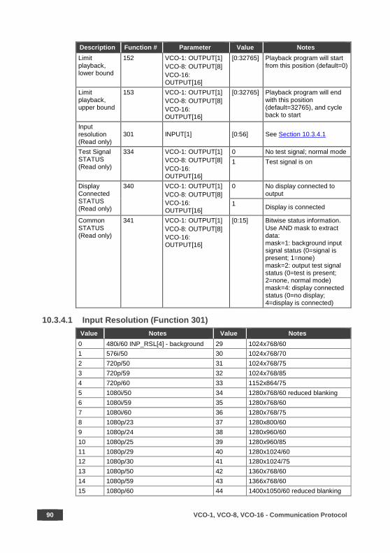
Description Function # Parameter Value Notes Limit playback, lower bound
152 VCO-1: OUTPUT[1] VCO-8: OUTPUT[8] VCO-16: OUTPUT[16]
[0:32765] Playback program will start from this position (default=0)
Limit playback, upper bound
153 VCO-1: OUTPUT[1] VCO-8: OUTPUT[8] VCO-16: OUTPUT[16]
[0:32765] Playback program will end with this position (default=32765), and cycle back to start
Input resolution (Read only)
301 INPUT[1] [0:56] See Section 10.3.4.1
Test Signal STATUS (Read only)
334 VCO-1: OUTPUT[1] VCO-8: OUTPUT[8] VCO-16: OUTPUT[16]
0 No test signal; normal mode 1 Test signal is on
Display Connected STATUS (Read only)
340 VCO-1: OUTPUT[1] VCO-8: OUTPUT[8] VCO-16: OUTPUT[16]
0 No display connected to output
1 Display is connected
Common STATUS (Read only)
341 VCO-1: OUTPUT[1] VCO-8: OUTPUT[8] VCO-16: OUTPUT[16]
[0:15] Bitwise status information. Use AND mask to extract data: mask=1: background input signal status (0=signal is present; 1=none) mask=2: output test signal status (0=test is present; 2=none, normal mode) mask=4: display connected status (0=no display; 4=display is connected)
10.3.4.1 Input Resolution (Function 301) Value Notes Value Notes
0 480i/60 INP_RSL[4] - background 29 1024x768/60 1 576i/50 30 1024x768/70 2 720p/50 31 1024x768/75 3 720p/59 32 1024x768/85 4 720p/60 33 1152x864/75 5 1080i/50 34 1280x768/60 reduced blanking 6 1080i/59 35 1280x768/60 7 1080i/60 36 1280x768/75 8 1080p/23 37 1280x800/60 9 1080p/24 38 1280x960/60 10 1080p/25 39 1280x960/85 11 1080p/29 40 1280x1024/60 12 1080p/30 41 1280x1024/75 13 1080p/50 42 1360x768/60 14 1080p/59 43 1366x768/60 15 1080p/60 44 1400x1050/60 reduced blanking

VCO-1, VCO-8, VCO-16 - Communication Protocol 91
Value Notes Value Notes 16 1080sf/23 45 1400x1050/60 17 1080sf/24 46 1400x1050/75 18 1080sf/25 47 1440x900/60 reduced blanking 19 1080sf/29 48 1440x900/60 reduced blanking 20 1080sf/30 49 1440x900/75 21 640x480/60 50 1440x900/85 22 640x480/72 51 1600x1200/60 23 640x480/75 52 1680x1050/60 reduced blanking 24 640x480/85 53 1680x1050/60 25 800x600/60 54 1920x1200/60 reduced blanking 26 800x600/72 55 UNIDENTIFIED INPUT SIGNAL 27 800x600/75 56 NO INPUT SIGNAL 28 800x600/85


SAFETY WARNING Disconnect the unit from the power supply before opening and servicing
For the latest information on our products and a list of Kramer distributors, visit our Web site where updates to this user manual may be found.
We welcome your questions, comments, and feedback.
www.kramerAV.com [email protected]
P/N: 2900-300592 Rev: 1


