VBF2, VBF3 Control Ball Valves With Flanged …...VBF2, VBF3 CONTROL BALL VALVES WITH FLANGED...
12
PRODUCT DATA 63-2649-06 VBF2, VBF3 Control Ball Valves With Flanged Connections APPLICATION The VBF2 Two-Way and the VBF3 Three-Way Ball Valve Assemblies, with and without actuators, control hot and chilled water with glycol solutions up to 50% in heating, ventilating, and air conditioning (HVAC) systems to provide two-position or modulating functions. These valve assemblies can be ordered with or without factory-mounted non-spring return or spring return direct-coupled actuators (DCA). FEATURES All Models • Sizes from 4 to 6 inch with ANSI Class 125 flanged connections. • Equal percentage or linear flow characteristics. • Choice of four, factory-installed actuation control schemes: Floating, Modulating (2-10 V), Spring Return 24V 2-Position, Spring Return Modulating/Floating. • Field configurable for normally open or normally closed fail-safe position. • Removable manual operating handle to control valve during installation or in an event of power failure. • Optional NEMA 3R (IP54) rated enclosure for outdoor applications. • Option of four actuator mounting positions on the valve. • Wide range of C V choices from 91 to 650. • Valve ball and stem 316 stainless steel. VBF2 (Two-way) • ANSI Class IV leakage specification (0.01% of C V ). VBF3 (Three-way) • Mixing or Diverting control and ANSI Class IV leakage specification (.01% of C V ) for all sizes except as noted below. • VBF3 4 inch with 327 C V , 5 inch with 400 C V , and 6 inch with 650 C V . • Mixing control only. • Class IV (.01% of C V ) leakage A to AB. • Class III (.1% of C V ) leakage B to AB. • Globe valve A-B-AB flow pattern (side B port) VBF2 VBF3 Contents Application ..................................................................................... 1 Features .......................................................................................... 1 Specifications ............................................................................... 2 Ordering Information ................................................................ 2 Installation .................................................................................... 5 Operation and Checkout .......................................................... 11 Typical Specifications ............................................................... 12
Transcript of VBF2, VBF3 Control Ball Valves With Flanged …...VBF2, VBF3 CONTROL BALL VALVES WITH FLANGED...
PRODUCT DATA
63-2649-06
VBF2, VBF3 Control Ball ValvesWith Flanged Connections
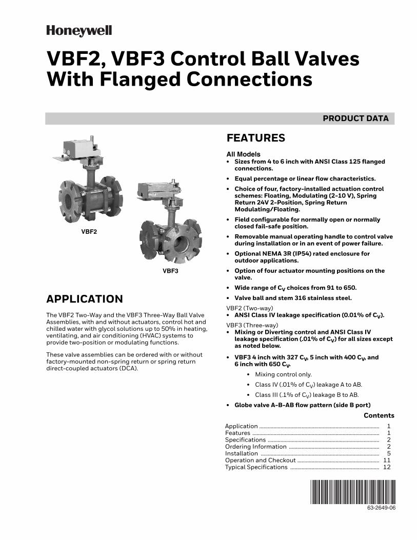
APPLICATIONThe VBF2 Two-Way and the VBF3 Three-Way Ball Valve Assemblies, with and without actuators, control hot and chilled water with glycol solutions up to 50% in heating, ventilating, and air conditioning (HVAC) systems to provide two-position or modulating functions.
These valve assemblies can be ordered with or without factory-mounted non-spring return or spring return direct-coupled actuators (DCA).
FEATURESAll Models• Sizes from 4 to 6 inch with ANSI Class 125 flanged
connections.
• Equal percentage or linear flow characteristics.
• Choice of four, factory-installed actuation control schemes: Floating, Modulating (2-10 V), Spring Return 24V 2-Position, Spring Return Modulating/Floating.
• Field configurable for normally open or normally closed fail-safe position.
• Removable manual operating handle to control valve during installation or in an event of power failure.
• Optional NEMA 3R (IP54) rated enclosure for outdoor applications.
• Option of four actuator mounting positions on the valve.
• Wide range of CV choices from 91 to 650.
• Valve ball and stem 316 stainless steel.
VBF2 (Two-way)• ANSI Class IV leakage specification (0.01% of CV).
VBF3 (Three-way)• Mixing or Diverting control and ANSI Class IV
leakage specification (.01% of CV) for all sizes except as noted below.
• VBF3 4 inch with 327 CV, 5 inch with 400 CV, and 6 inch with 650 CV.
• Mixing control only.
• Class IV (.01% of CV) leakage A to AB.
• Class III (.1% of CV) leakage B to AB.
• Globe valve A-B-AB flow pattern (side B port)
VBF2
VBF3
ContentsApplication ..................................................................................... 1Features .......................................................................................... 1Specifications ............................................................................... 2Ordering Information ................................................................ 2Installation .................................................................................... 5Operation and Checkout .......................................................... 11Typical Specifications ............................................................... 12
VBF2, VBF3 CONTROL BALL VALVES WITH FLANGED CONNECTIONS
63-2649—06 2
ORDERING INFORMATIONWhen purchasing replacement and modernization products from your TRADELINE® wholesaler or distributor, refer to the TRADELINE® Catalog or price sheets for complete ordering number. If you have additional questions, need further information, or would like to comment on our products or services, please write or phone:
1. Your local Honeywell Environmental and Combustion Controls Sales Office (check white pages of your phone directory).
2. Honeywell Customer Care1985 Douglas Drive NorthGolden Valley, Minnesota 55422-4386
3. http://customer.honeywell.com or http://customer.honeywell.caInternational Sales and Service Offices in all principal cities of the world. Manufacturing in Belgium, Canada, China, Czech Republic, Germany, Hungary, Italy, Mexico, Netherlands, United Kingdom, and United States.
SPECIFICATIONSModels: See Table 2.
Dimensions: See Fig. 1 and 2.
Body Style: Two-way ball valve, straight-through flow, full or reduced port using patented flow control insert.
Three-way ball valve, A-B-AB characterized flow, using laser-milled stainless steel control ball.
Combination ANSI 125/PN16 flanged connections.
Body Size: 4 to 6 inch.
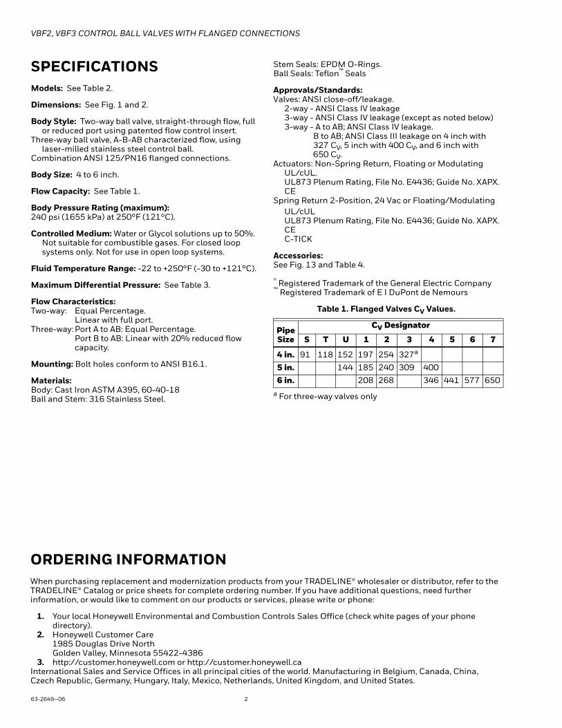
Flow Capacity: See Table 1.
Body Pressure Rating (maximum):240 psi (1655 kPa) at 250°F (121°C).
Controlled Medium: Water or Glycol solutions up to 50%. Not suitable for combustible gases. For closed loop systems only. Not for use in open loop systems.
Fluid Temperature Range: -22 to +250°F (-30 to +121°C).
Maximum Differential Pressure: See Table 3.
Flow Characteristics:Two-way: Equal Percentage.
Linear with full port.Three-way: Port A to AB: Equal Percentage.
Port B to AB: Linear with 20% reduced flow capacity.
Mounting: Bolt holes conform to ANSI B16.1.
Materials:Body: Cast Iron ASTM A395, 60-40-18Ball and Stem: 316 Stainless Steel.
Stem Seals: EPDM O-Rings.Ball Seals: Teflon™ Seals
Approvals/Standards:Valves: ANSI close-off/leakage.
2-way - ANSI Class IV leakage3-way - ANSI Class IV leakage (except as noted below)3-way - A to AB; ANSI Class IV leakage.
B to AB; ANSI Class III leakage on 4 inch with 327 CV, 5 inch with 400 CV, and 6 inch with 650 CV.
Actuators: Non-Spring Return, Floating or ModulatingUL/cUL.UL873 Plenum Rating, File No. E4436; Guide No. XAPX.CE
Spring Return 2-Position, 24 Vac or Floating/ModulatingUL/cUL UL873 Plenum Rating, File No. E4436; Guide No. XAPX.CEC-TICK
Accessories:See Fig. 13 and Table 4.
® Registered Trademark of the General Electric Company™ Registered Trademark of E I DuPont de Nemours
Table 1. Flanged Valves CV Values.
a For three-way valves only
Pipe Size
CV Designator
S T U 1 2 3 4 5 6 7
4 in. 91 118 152 197 254 327a
5 in. 144 185 240 309 400
6 in. 208 268 346 441 577 650

VBF2, VBF3 CONTROL BALL VALVES WITH FLANGED CONNECTIONS
3 63-2649—06
Table 2. Model Selection.
Application Notes
Required Operating TorqueBoth Honeywell non-spring return and spring return direct coupled actuators can be utilized with the VBF2 and VBF3 valves. See Table 3, which lists the different torque actuator options. Larger torque actuators may be used, but there is no increase in close-off pressure rating.
Table 3. Close-off Pressure Ratings
Flow CharacteristicsVBF2 Two-Way Ball Valves have:• an equal percentage flow characteristic.
VBF3 Three-Way Ball Valves have:• between ports A and AB: an equal percentage flow
characteristic.• between ports B and AB: a linear flow characteristic.
Valve Fitting Body / Flow Size CV T / P Trim Enclosure ActuatorVB = valve, ball
F = Flanged2 = 2 way3 = 3 way
inch S.I. metricJ 4 DN100K 5 DN125L 6 DN150
S
CV Designator: See Table 1.
TU1234567
1 = ANSI Valve constructionS = Stainless Steel
0 = no enclosureR = NEMA 3R enclosure
X = no actuatorA = NSR, FloatingB = NSR, ModulatingC = SR, 2-Position, 24 VacD = SR, Floating/Modulating
VB F 2 A B 1 S 0 A
Valve Size
Actuator Torque
88 in.-lb (10 Nm)
175 in.-lb (20 Nm)
175 in.-lb (20 Nm)
2-position300 in.-lb (34 Nm)
Close Off Pressure Rating (psid)4 in. 70 70 70 70
5 in. 70 70 70 70
6 in. 70 70

VBF2, VBF3 CONTROL BALL VALVES WITH FLANGED CONNECTIONS
63-2649—06 4
Fig. 1. VBF2 dimensions in inches (millimeters). Fig. 2. VBF3 dimensions in inches (millimeters).
A
B
C
E
Size Model A B C D (depth) E Wt.(in.) Number in. in. in. (not shown) in. lb (mm) (mm) (mm) in. (mm) (mm) (kg)4 VBF2J 11 9 13-1/4 9 18-3/4 65 (278) (229) (337) (229) (476) (31)5 VBF2K 12-3/8 10 14-1/4 10 19 75 (352) (254) (362) (254) (483) (34)6 VBF2L 13-7/8 11 15-1/8 11 19-7/8 90 (352) (278) (384) (278) (505) (41)
M13732
A
B
C
E
Size Model A B C D (depth) E Wt.(in.) Number in. in. in. (not shown) in. lb (mm) (mm) (mm) in. (mm) (mm) (kg)4 VBF3J 11-7/8 9 14-1/8 10-3/8 18-1/2 75 (278) (229) (337) (229) (470) (34)5 VBF3K 13-7/8 10 15-1/8 12 19-3/8 90 (352) (254) (362) (254) (483) (41)6 VBF3L 15-7/8 11 16-1/8 13-3/8 20-1/2 105 (403) (278) (410) (521) (521) (48)
M13733A
AB PORT
B PORT
A PORT

VBF2, VBF3 CONTROL BALL VALVES WITH FLANGED CONNECTIONS
5 63-2649—06
INSTALLATION
When Installing this Product...1. Read these instructions carefully. Failure to follow
them could damage the product or cause a hazard-ous condition.
2. Check ratings given in instructions and on the prod-uct to ensure the product is suitable for your applica-tion.
3. Installer must be a trained, experienced service tech-nician.
4. After installation is complete, check out product operation as provided in these instructions.
Preparation
SafetyHoneywell assumes no responsibility for damages or injuries resulting from non-compliance with installation instructions or standard good practice when mounting, operating, or maintaining the valves, even if not explicitly mentioned in the installation instructions.
CAUTIONEquipment Damage Hazard.Foreign particles like dirt and metal chips can damage the ball seals.
For trouble-free operation of the product, good installation practice must include initial system flushing, and chemical water treatment. Clean the lines upstream of particles larger than 1/16 inch diameter (welding slag, pipe scale, sand and other suspended particulate). Use of a 50 micron (or finer) system side stream filter is suggested. Remove all filters before flushing.
Do not use boiler additives, solder flux and wetted materials which are petroleum based or contain mineral oil, hydrocarbons, or ethylene glycol acetate. Compounds which can be used, with minimum 50% water dilution, are diethylene glycol, ethylene glycol, and propylene glycol (antifreeze solutions).
If installing these valves in an addition to, or retrofitting an existing building, do not assume that the fluid in the existing piping meets these criteria.
Valve Installation LocationSelect a location where the valve and actuator will be accessible, once installed. Allow sufficient space for servicing the valve and actuator. Clearance for valve installation is dependent on actuator size and the valve pipe size. See Figures 1 and 2 for valve body dimensions. Refer to actuator literature for actuator dimensions.
1. Clean the lines upstream of the valve to remove parti-cles larger than 1/16 inch diameter (welding slag, pipe scale and other contaminants). Upstream instal-lation of a 20 mesh strainer is recommended.
2. Air should be eliminated from the system so the valves remain full of fluid during operation.
3. Straight sections of piping upstream and down-stream of the valves are not necessary for proper operation. Reducing bushings or flanges may be attached directly to valves. Standard adapters are adequate for installation of flow control valves.
4. Proceed with installation once the system specifics (expansion/contraction of the system and its medium as well as operating pressures) are within tolerances.
5. Do not lift the valve by holding the stem.
Mounting Valve1. Before installing the valve, rotate the valve stem to
make sure that the valve stem operates freely. Impaired stem operation can indicate that the stem was bent by rough handling. This condition can require replacing the valve.
2. Protect the stem from damage due to bending or scratching.
3. For horizontal piping, install the valve so the actuator is above the valve body. Install the valve in any posi-tion between vertical and horizontal. Do not install the valve with the stem below horizontal or upside down. For vertical piping, the actuator can be mounted in any orientation.
4. Hoist valve by its body only. Do not lift by stem, bon-net, flanges, or flange holes. (See Fig. 3 for proper hoisting method.)
Fig. 3. Proper hoisting of VBF Valves.
5. Mount the valve between aligned pipes. Mounting the valve on pipes that are not aligned causes leak-age at the valve-to-pipe connection.
Fig. 4. Piping must prevent leakage.
M13752
M22591

VBF2, VBF3 CONTROL BALL VALVES WITH FLANGED CONNECTIONS
63-2649—06 6
Fig. 5. Basic pipe orientation.
6. Iron valves are mechanically compatible with stan-dard ANSI 150 lb flat-faced or raised-face steel flanges, or with 125 lb cast iron flanges.
7. Release system pressure and drain the valve pipe section so the medium (water or glycol solution) does not leak out of the valve body during installation.
8. Mount three-way valves as shown in Figure 9, according to whether they are to be used for mixing or diverting control. Note that 4 inch VBF3 valves with 327 CV, 5 inch with 400 CV, and 6 inch with 650 CV must be used in mixing applications only.
9. Use a gasket material recommended for the medium to be handled (e.g., 1/16 inch thick ring type, filled asbestos gaskets). (Not supplied by Honeywell.)
10. Use mounting bolts long enough so the nuts can use the full length of the nut threads. Use four (4) 5/8 inch bolts to connect 4 inch valves to mating flanges in pipework; use six (6) 5/8 inch bolts for 5 and 6 inch valves.
Fig. 6. Basic proper bolt length.
Fig. 7. Boiler bypass for reset control
Fig. 8. Three-way mixing valve operation with coil bypass.
Fig. 9. Three-way ball valve flow orientation (not to scale).
M22592
133 IN-LB(15 NM)
M13753
ABA
B
M13793
BOILER
PUMP
VB3MIXEDDISCHARGEWATER TO HEAT LOAD
BYPASS
AB A
B
M19523A
HEATING COIL FULL H EAT
5 GPM
5 GPM
2.5 GPM
5 GPM
AB A
B
P ROPORTIONED H EAT
2.5 GPM
S UPPLY M AIN
RETURN MAIN
5 GPM
5 GPM
AB VBF3
VBF3
VBF3
A
B
N O H EAT
NO FLOW THROUGH COIL
M13737
SUPPLY
RETURNAB PORT A PORT
B PORT
COILSUPPLY
RETURN
AB PORT A PORT
B PORT
COIL
MIXINGDIVERTING

VBF2, VBF3 CONTROL BALL VALVES WITH FLANGED CONNECTIONS
7 63-2649—06
Stem rotation:1. For two-way valves:
a. Rotate stem clockwise to open.b. Rotate stem counter clockwise to close.
2. For three-way valves:a. Rotate stem clockwise to increase A to AB flow.b. Rotate stem counter clockwise to increase B to AB flow.
Fig. 10. Orientation of ball in valve
Fig. 11. Vertical Valve Installation Fig. 12. Acceptable valve angle from vertical (when installed in horizontal piping)
PORTCLOSED
PORTCLOSED
STEM ROTATION
COIL FLOW
STEM ROTATION
BYPASS FLOW
AB
B
A
M23853
M13741
45° 45°
M13740
VBF2, VBF3 CONTROL BALL VALVES WITH FLANGED CONNECTIONS
63-2649—06 8
Mounting ActuatorFor information on mounting, refer to the Product Data Sheet for the specific Honeywell actuator coupled to the valve. It is important to have the correct actuator available for the installation.
CheckoutFor instructions for operating the valve actuator, see the specific actuator's Product Data Sheet. Operate the control system and check valve operation to determine that the valve stem positions the ball smoothly through its full stroke without binding.
Ensure that the actuator selected provides the force to position the valve ball. For electric spring-return actuators, the actuator provides normally closed or normally open operation on electric power or pressure failure, depending on the valve/actuator combination selected.
GeneralSpring return actuators return the valve to its normal position (open or closed, depending on the actuator and valve selected) in the event of a power failure. Non-spring return actuators hold the last commanded position.
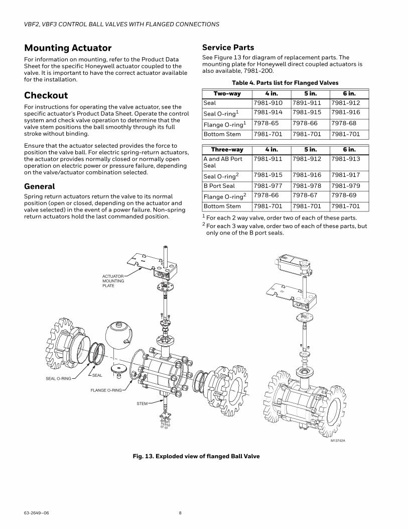
Service PartsSee Figure 13 for diagram of replacement parts. The mounting plate for Honeywell direct coupled actuators is also available, 7981-200.
Table 4. Parts list for Flanged Valves
1 For each 2 way valve, order two of each of these parts.2 For each 3 way valve, order two of each of these parts, but
only one of the B port seals.
Fig. 13. Exploded view of flanged Ball Valve
Two-way 4 in. 5 in. 6 in.Seal 7981-910 7891-911 7981-912
Seal O-ring1 7981-914 7981-915 7981-916
Flange O-ring1 7978-65 7978-66 7978-68
Bottom Stem 7981-701 7981-701 7981-701
Three-way 4 in. 5 in. 6 in.A and AB Port Seal
7981-911 7981-912 7981-913
Seal O-ring2 7981-915 7981-916 7981-917
B Port Seal 7981-977 7981-978 7981-979
Flange O-ring2 7978-66 7978-67 7978-69
Bottom Stem 7981-701 7981-701 7981-701
SEAL O-RINGSEAL
STEM
FLANGE O-RING
M13742A
ACTUATOR MOUNTING PLATE

VBF2, VBF3 CONTROL BALL VALVES WITH FLANGED CONNECTIONS
9 63-2649—06
Mounting Plate Adjustment The Actuator Mounting Plate can be rotated to a different position for installation in confined spaces. This is accomplished as follows:
1. Remove the four bolts and lock washers that hold the mounting plate to the valve stem housing and set them aside.
2. Rotate mounting plate around valve top to the desired position.
NOTE: There are four positions possible (incre-ments of 90 degrees from each other) for the mounting plate position
3. Once the mounting plate is in the desired position, re-insert the bolts through the lock washers and into the four bolt holes in the valve stem housing.
4. Tighten bolts to the valve body securing the mount-ing plate.
See Fig. 14 for valve exploded view.
Fig. 14. Mounting Plate Adjustment Bolts
Electrical Installation1. If necessary, remove actuator wiring cover.2. Wire actuator using Figures 15 through 23 for the
application required. 3. Replace cover.
The following wiring instructions are provided as a convenience to the installing contractor. For more detailed information about these actuators, refer to the Product Data sheets for the corresponding Honeywell actuator as follows:
Literature # Actuator Model and Literature Type63-2632 MN6110, MN7510 (Product Data)63-2588 MN6134, MN7234 (Product Data)63-2607 MS7510, MS7520, MS8110, MS8120
(Product Data)
Wiring
VALVES WITH NON-SPRING RETURN ACTUATORS (MN6110A, MN6134A, MN7234A, MN7510A)
Fig. 15. Wiring for On/Off Control
Fig. 16. Wiring for Floating Control
M13745
VALVE STEM HOUSING
BOLTS WITH LOCK WASHERS (4)
MOUNTING PLATE
DRIVE SHAFT
432
FLOATING ACTUATOR
24 VAC
1
1 POWER SUPPLY. PROVIDE DISCONNECT MEANSAND OVERLOAD PROTECTION AS REQUIRED.CONNECTION REQUIRED FOR SPST CONTROL.2
CONTROLLER
2
Direct
ReverseService/Off
M18945A
432
FLOATING ACTUATOR
24 VAC
Direct
ReverseService/Off
1
1 POWER SUPPLY. PROVIDE DISCONNECT MEANSAND OVERLOAD PROTECTION AS REQUIRED.
FLOATINGCONTROLLER
M18946A

VBF2, VBF3 CONTROL BALL VALVES WITH FLANGED CONNECTIONS
63-2649—06 10
Fig. 17. Wiring for Modulating Control
VALVES WITH SPRING RETURN ACTUATORS (MS7510A, MS7520A, MS8110A, MS8120A)
Fig. 18. Wiring for On/Off Control
Fig. 19. Wiring for Floating Control (Floating mode setting)
Fig. 20. Override to full open (Modulating mode setting)
Fig. 21. Wiring for Proportioning Controllers (Modulating mode setting)
24 VAC
1
1 POWER SUPPLY. PROVIDE DISCONNECT MEANSAND OVERLOAD PROTECTION AS REQUIRED.
PROPORTIONALCONTROLLER
+
-
FEEDBACK
1 32 5
PROPORTIONAL ACTUATOR
FEE
DB
AC
K
+
0(2)-10 VDC OF 0(4)-20 mA CONTROL SIGNAL ACCEPTABLE.SET CONTROL SIGNAL DIP SWITCH TO "OFF" FOR VOLTAGE.SET TO "ON" FOR CURRENT.
2
2
2 -10 Vdc
2 -10 Vdc
0 -10 Vdc
0 -10 Vdc
M18947A
ACTUATOR
SPST24 VAC1
1
2
2
LINE VOLTAGE POWER SUPPLY. PROVIDE DISCONNECT MEANS AND OVERLOAD PROTECTION AS REQUIRED.
24 VDC SUPPLY ACCEPTABLE.
ENSURE PROPER GROUNDING OF ACTUATOR CASE.
V1
2
M19718C3
3
24 VAC 1
1
2
3
2
LINE VOLTAGE POWER SUPPLY. PROVIDE DISCONNECT MEANS AND OVERLOAD PROTECTION AS REQUIRED.
24 VDC SUPPLY ACCEPTABLE.
SET SWITCH TO FLOATING.
M19573B
ACTUATOR
V
OR +
OR N/A
FEEDBACK 5
4
3
1
2
2-10 VDC 10-2 VDC 0-10 VDC 10-0 VDC Fltg, fwd Fltg, rev
3
4
4
ENSURE PROPER GROUNDING OF ACTUATOR CASE.
ACTUATOR
0/2 TO 10 VDCPROPORTIONINGCONTROLLER
24 VAC1
1
2
3
2
LINE VOLTAGE POWER SUPPLY. PROVIDE DISCONNECT MEANS AND OVERLOAD PROTECTION AS REQUIRED.
24 VDC SUPPLY ACCEPTABLE.
SET SWITCH TO MODULATING.
V
OR +
OR N/A
FEEDBACK–
+
FEEDBACK
5
4
3
1
2
M19576A
2-10 VDC10-2 VDC0-10 VDC10-0 VDCFltg, fwdFltg, rev
3SPDT
ACTUATOR
0/2 TO 10 VDCPROPORTIONINGCONTROLLER
24 VAC1
1
2
3
2
LINE VOLTAGE POWER SUPPLY. PROVIDE DISCONNECT MEANS AND OVERLOAD PROTECTION AS REQUIRED.
24 VDC SUPPLY ACCEPTABLE.
SET SWITCH TO MODULATING.
V
OR +
OR N/A
FEEDBACK–
+
FEEDBACK
5
4
3
1
2
M19574B
2-10 VDC10-2 VDC0-10 VDC10-0 VDCFltg, fwdFltg, rev
3
4 ENSURE PROPER GROUNDING OF ACTUATOR CASE.
4
ACTUATOR
4 TO 20 mA PROPORTIONING CONTROLLER
24 VAC 1
1
2
3
2
490 TO 510 OHMS, 1/2 W
MINIMUM
LINE VOLTAGE POWER SUPPLY. PROVIDE DISCONNECT MEANS AND OVERLOAD PROTECTION AS REQUIRED. 24 VDC SUPPLY ACCEPTABLE. SET SWITCH TO MODULATING.
V
OR +
OR N/A
FEEDBACK –
+
FEEDBACK
5
4
3
1
2
M22282B
2-10 VDC 10-2 VDC 0-10 VDC 10-0 VDC Fltg, fwd Fltg, rev
3
4 ENSURE PROPER GROUNDING OF ACTUATOR CASE.
4

VBF2, VBF3 CONTROL BALL VALVES WITH FLANGED CONNECTIONS
11 63-2649—06
Fig. 22. Override to full closed (Modulating mode setting)
Fig. 23. Wiring for Proportioning controllers operating multiple actuators (Modulating mode setting)
OPERATION AND CHECKOUTOnce both the mechanical and electrical installations are complete:
1. Cycle the actuator to verify that the direction of rota-tion suits the control sequence.
2. If the rotation direction is incorrect:a. For 2-position control actuators: Remount actua-
tor on the bracket.b. For floating control actuators: Reverse two control
signal wires (CW/CCW).c. For analog control actuators either:
(1) Reposition reverse/direct acting switch, or(2) Remount actuator on the bracket.
3. If the control scheme requires fail-safe operation, ensure that, upon removal of power, the fail position coincides with the control sequence.
4. If the fail safe position is incorrect, remove and rein-stall the actuator in the opposite orientation as fol-lows:a. Loosen the shaft coupling bolt using a 10 mm
wrench.b. Loosen all other mounting bolts connecting the
actuator to the mounting bracket, and set aside.c. Remove the actuator from the valve shaft.d. Move the actuator coupling to the opposite side
of the actuator, as displayed in Figure 24.
Fig. 24. Mounting shaft coupling to actuator opposite side.
(1) Remove the retainer clip from the shaft cou-pling and set it aside for later use.
(2) Remove shaft coupling from one side of the actuator.
(3) Replace the shaft coupling on the opposite side of the actuator, aligning it based on the stroke labelling.
(4) Replace the retainer clip on the shaft coupling using the groove of the coupling.
e. Reconnect the actuator to the valve mounting bracket by replacing the screws previously removed (step b)
f. Tighten the shaft coupling bolt using a 10 mm wrench.
For detailed actuator information, see Honeywell literature:• 63 2632—MN6110, MN7510 Product Data• 63-2588—MN6134, MN7234 Product Data• 63-2607—MS7510, MS7520, MS8110, MS8120
Product Data
ACTUATOR
0/2 TO 10 VDCPROPORTIONINGCONTROLLER
24 VAC1
1
2
3
2
LINE VOLTAGE POWER SUPPLY. PROVIDE DISCONNECT MEANS AND OVERLOAD PROTECTION AS REQUIRED.
24 VDC SUPPLY ACCEPTABLE.
SET SWITCH TO MODULATING.
V
OR +
OR N/A
FEEDBACK–
+
FEEDBACK
5
4
3
1
2
M19577A
2-10 VDC10-2 VDC0-10 VDC10-0 VDCFltg, fwdFltg, rev
3SPST
ACTUATOR
0/2 TO 10 VDCPROPORTIONINGCONTROLLER
1
2
3
2
LINE VOLTAGE POWER SUPPLY. PROVIDE DISCONNECT MEANS AND OVERLOAD PROTECTION AS REQUIRED.
24 VDC SUPPLY ACCEPTABLE.
SET SWITCH TO MODULATING.
V
OR +
OR N/A
FEEDBACK5
4
3
1
2
M22288A
2-10 VDC10-2 VDC0-10 VDC10-0 VDCFltg, fwdFltg, rev
3
ACTUATOR
V
OR +
OR N/A
FEEDBACK5
4
3
1
2
2-10 VDC10-2 VDC0-10 VDC10-0 VDCFltg, fwdFltg, rev
3
24 VAC1
24 VAC1
224 VAC1
HOT
COM
–
+
4 ENSURE PROPER GROUNDING OF ACTUATOR CASE.
M19579A

VBF2, VBF3 CONTROL BALL VALVES WITH FLANGED CONNECTIONS
Automation and Control SolutionsHoneywell International Inc.
1985 Douglas Drive North
Golden Valley, MN 55422
customer.honeywell.com
® U.S. Registered Trademark© 2016 Honeywell International Inc.63-2649—06 M.S. Rev. 10-16 Printed in United States
By using this Honeywell literature, you agree that Honeywell will have no liability for any damages arising out of your use or modification to, the literature. You will defend and indemnify Honeywell, its affiliates and subsidiaries, from and against any liability, cost, or damages, including attorneys’ fees, arising out of, or resulting from, any modification to the literature by you.
TYPICAL SPECIFICATIONS
Actuated Ball ValveValve housing shall consist of cast iron, rated at no less than 240 psi at 250°F. Valve housing shall have ANSI Class 125 flanges. Valve ball shall consist of stainless steel with parabolic ports to make flow control equal percentage. Valve shall have a blow-out proof stem with two EPDM O-Rings. Valve shall have EPDM O-Rings behind ball seals to allow for a close-off pressure of 70 psi with 88 in.-lbs of torque for 4 and 5 inch valves. Six inch valves shall require actuators with 140 in.-lbs of torque for flow rates under 700 gpm. Valve shall be available with a minimum of 5 unique CV values for each size. 3-Way Valve: Bypass CV shall be 80% of Through CV.
Valve ActuatorControl valve actuator shall accept analog modulating floating (tri-state), or two-position signal as indicated in the control sequence. Actuators shall be by Honeywell. Actuator shall provide minimum torque required for full valve shutoff position. Wiring terminals shall be provided for installation to control signal and power wiring.
ACCESSORIESIdentification tags shall be available for all valves; tags shall be indelibly marked with CV, model number and location.