Miniature Circuit Breaker Residual Current Circuit Breaker ...

VB2 PlusCircuit Breaker User Manual


Safety Instruction
Precautions
Transport and Handling
DeliveryPlease comply with the following precautions for your safety:
• Select the breaker according to operating conditions, otherwise
it will result in faults such as damage to insulation, short-circuit
and overheating
• Check that rated operating parameters of the breaker are not
exceeded during service
• Ensure that installation, operation and maintenance are carried
out only by qualified operators who have received relevant
training. The replacement of parts should be done by qualified
electricians or GE service staff
• Be sure that the breaker is open before it moves from test
position to service position
• The main circuit and control circuit must be deenergized during
the maintenance and inspection, the breaker must be drawn
out of the switchgear and earth switch closed
Loading/unloading of the breaker units must only be carried out with either a crane if possibleDo not lift circuit breaker by inserting fork lift or trolly ties directly under it .Use a pallet or other support material between the circuit breaker and fork/trolley
Notes:- Avoid impact during handling- Do not subject to the mechanical damage
Important:• Lifting breaker must not be attached to the breaker poles or parts of the operating mechanism. Use lifting bores and lifting lugs
Upon reciept of the breakers , the following inspection must be done:• Check the goods for loss and damage (such as subjected to
water or dirt)• If there is any shortages,defects or damages,take notes and
if possible photogroaphs of the affected units and notify GE immediately
Thank you very much for using SecoVac VB2 Plus type indoor MV vacuum circuit breaker referred to produced by Shanghai GE Breakers Co., Ltd. To help you install and operate this breaker safely and effectively, please read this manual carefully and install, operate and maintain it according to this manual as well as installation codes and operation procedures related to electrical equipment.

Version Pole centre distance (mm) Rated current (A) Rated short-circuit breaking current (kA) Weight (kg)
Fixed 150 630~1250 31.5 115
Withdrawable 150 630~1250 31.5 125
Fixed 275 1250~2000 40 178
Withdrawable 275 1250~2000 40 208
Fixed 275 2500~4000 40 247
Withdrawable 275 2500~4000 40 297
Table1: The weight of circuit breakers
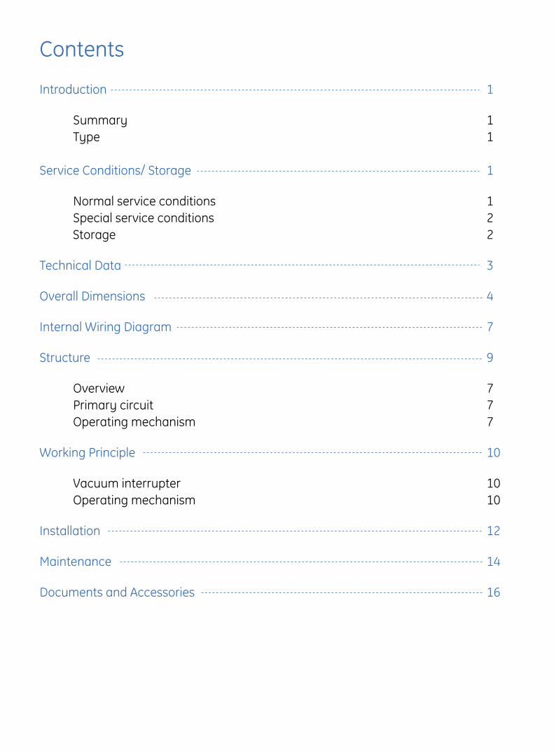
Contents
Introduction
Summary Type
Service Conditions/ Storage
Normal service conditions Special service conditions Storage
Technical Data
Overall Dimensions
Internal Wiring Diagram
Structure
Overview Primary circuit Operating mechanism
Working Principle
Vacuum interrupter Operating mechanism
Installation
Maintenance
Documents and Accessories
1
11
1
122
3
4
7
9
777
10
1010
12
14
16

1
IntroductionSummary
Type
The SecoVac VB2 Plus circuit breaker elaborately designed by GE Energy for three-phases A.C up to 17.5kV rated voltage, and can be used for in controlling and protecting electrical equipment in industrial, mining, power plants and substations applications. The product conforms to IEC62271-100. The breaker can be installed in the switchgear in fixed or withdrawable arrangements. It is the optimum choice for the control and protection of MV power systems.
SecoVacVB2 Plus -
W: Withdrawable, F:Fixed
Rated short-circuit breaking current (kA): 25,31.5,40
Rated current (A): 630,1250,1600,2000,2500,3150,4000 (Forced cooling)
Spring operating mechanism
Rated voltage: 7.2kV,12kV,17.5kV
SecoVac Series VB2 Plus type vacuum circuit breaker
-T □ □□ □/
Service ConditionsNormal service conditions• Unless otherwise specified, SecoVac VB2 Plus circuit breakers,
including the operating devices and the auxiliary equipment which form an integral part of them, are intended to be used in accordance with their rated operating parameter and normal service conditions listed as follows
• The ambient air temperature does not exceed 40℃ and its average value, measured over a period of 24h, does not exceed 35℃. The minimum operating ambient air temperature is -15℃. (storage and transportation is allowed at -30℃)
• The altitude does not exceed 1000m• The ambient air is not significantly polluted by dust, smoke,
corrosive and/or flammable gases, vapours or salt
• The conditions of humidity are as follows: – The average value of relative humidity, measured over a period of 24h, does not exceed 95%
– The average value of water vapour pressure, measured over a period of 24h, does not exceed 2.2kPa
– The average value of the relative humidity, measured over a period of one month, does not exceed 90%
– The average value of water vapour pressure, measured over a period of one month, does not exceed 1.8kPa
• Seismic intensity is not more than Zone4

2
If the actual service conditions differ from the normal service conditions, The circuit breaker and associating devices
and auxiliary equipment shall be designed and made to comply with any special service conditions required by the user
which must be discussed with GE in advance. Normally, the following special service conditions will be encountered:• At sites with altitude above 1000m, the effects of the reduction in dielectric strength of the air must be taken into account. GE
can supply circuit breakers which can be applied in areas less than 3000m above sea level. At this time, the insulation level in
switchgears should be taken into account and must be discussed with GE in advance
• The ambient temperature is above 40℃. The service current of circuit breaker shall be derated at certain factor, or fans shall be
installed for heat dissipation. Please confirm with GE in advance
Attentation:
• When circuit breakers are operated in areas with high humidity and/or major rapid temperature fluctuations, there is a risk of
condensation, thus
– Put the circuit breaker into operation as soon as possible after the package is dismantled – Put on the heater into service as soon as possible after the switchgear is installed – Please consult GE special application conditions
Special service conditions
Service Conditions
Storage• The product is applicable to normal transportation conditions, i.e. highway (floor above level 3) and pay attention to waterproofing• Do not store product other than as indicated on packaging.Damage is possible if stored on side/back or top• If immediate installation is not possible, basic package is required or original package is maintained. After inspection and stored, the
circuit breaker should be switched off and the spring mechanism should be discharged• The product shall be stored in dry and ventilated indoor place free of dust severe contamination, chemical corrosion and vibrations.
The climate condition conforms to related specifications in IEC 62271-1 and adequate air circulation shall be maintained. The store room temperature shall not be lower than -30℃. Check periodically to avoid condensation inside breaker

3
Technical Data
Control circuit data
Electrical Parameter
Rated voltage (V) Normal operation voltage range Energy storing period under rated operation voltage (s) Input Power (W)
110 DC 85%-110% <15s 150
125 DC 85%-110% <15s 150
220 DC 85%-110% <15s 150
110 AC 85%-110% <15s 150
220 AC 85%-110% <15s 150
Table3: Motor
Table2
Table4: Coils
Rated voltage (V)
Rated current (A)
Rated voltage (V)
Rated current (A)
Rated voltage (V)
Rated current (A)
Rated voltage (V)
Rated current (A)
DC 24** 23.3 DC 30** 14.6 DC 36 11.5 DC 48 8.4
DC 60 5.6 DC 110 2.2 DC 220 1.1
AC 110 2.2 AC 220 1.1
* 4000A is VCB with force cooling.** 24V, 30V plesse contact GE.
Rated Voltage kV 3.3~12 15 17.5
Rated Current A630/1250/1600/2000/
2500/3150/4000*630/1250/1600/2000/
2500/3150/4000*630/1250/1600/2000/
2500/3150/4000*
Frequency 50/60Hz
Rated Power Frequency Withstand Voltage (1min)) kV 28 36 38
Rated Lightning Impulse Withstand Voltage (Peak Values) kV 75 95 95
Rated Short Circuit Breaking Current kA 25/31.5/40 25/31.5/40 25/31.5/40
Rated Short Time Withstand Current (3s) kA 25/31.5/40 25/31.5/40 25/31.5/40
Rated Peak Withstand Current kA 65/82/104 65/82/104 65/82/104
Rated Peak Making Current kA 65/82/104 65/82/104 65/82/104
Capacitor Bank Switching Current A 400 (C2)
Electrical Endurance No. of Times E2
Mechanical Endurance No. of Times 10,000 (M2)
Rated Auxiliary Control Voltage V 36/48/60/110/220/240V DC 110/220V AC
Opening Time ms 35~70
Breaking Time ms 25~35
Closing Time ms 40~50
4
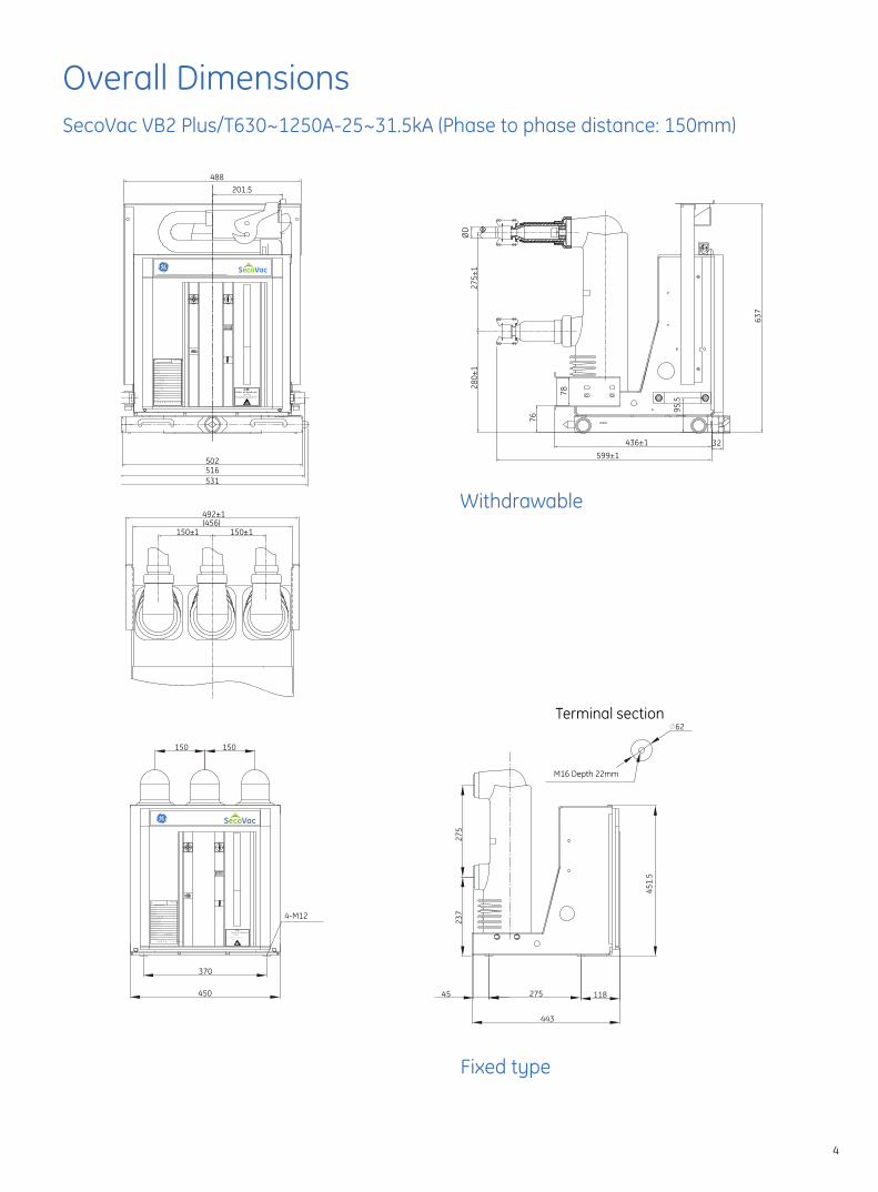
Overall DimensionsSecoVac VB2 Plus/T630~1250A-25~31.5kA (Phase to phase distance: 150mm)
Rated cable-charging breaking current 额 定 电 缆 充 电 开 断 电 流
motor voltage电 机 电 压
产 品 型 号
出 厂 编 号Serial number额 定 电 压
Type designation
额 定 电 流
额 定 频 率
Rated voltage(Ur)
Rated normal current(Ir)
Rated frequency额 定 雷 电 冲 击 耐 压 (峰值)Rated lightning impulse withstand voltage(Up)额 定 短 路 开 断 电 流Rated short-circuit breaking current(Isc)额 定 短 时 耐 受 电 流Rated short time withstand current (4s)
分 闸 合 闸 装 置 电 压
执 行 标 准
出 厂 日 期
Rated supply voltage of closing and opening devices
Relevant standarder
Manufacture date
GE Consumer & Industrial Systems
Weight重 量
e
上 海 通 用 电 气 开 关 有 限 公 司Shanghai GE Breakers Co.,Ltd.
kg
V
V
kV
kA
A
kA
Hz
kV
A
户内高压真空断路器Vacuum circuit breaker
额 定 操 作 顺 序Rated operating sequence O-0.3s-CO-180s-CO Warning!
High voltage dangerous! Always observe the instruction manual and follow the rules.
201.5488
502
531
150±1 150±1
492±1(456)
516
599±132
280±
127
5±1
436±1
76
78
95.5
637
ØD
高压危险!请严格遵守操作规程。注意!
Warning!High voltage dangerous! Always observe the instruction manual and follow the rules.
Rated cable-charging breaking current 额 定 电 缆 充 电 开 断 电 流
motor voltage电 机 电 压
产 品 型 号
出 厂 编 号Serial number额 定 电 压
Type designation
额 定 电 流
额 定 频 率
Rated voltage(Ur)
Rated normal current(Ir)
Rated frequency额 定 雷 电 冲 击 耐 压 (峰值)Rated lightning impulse withstand voltage(Up)额 定 短 路 开 断 电 流Rated short-circuit breaking current(Isc)额 定 短 时 耐 受 电 流Rated short time withstand current (3s)
分 闸 合 闸 装 置 电 压
执 行 标 准
出 厂 日 期
Rated supply voltage of closing and opening devices
Relevant standarder
Manufacture date
Industrial Solutions
Weight重 量
e
上 海 通 用 电 气 开 关 有 限 公 司Shanghai GE Breakers Co.,Ltd.
kg
V
V
kV
kA
A
kA
Hz
kV
A
户内高压真空断路器Vacuum circuit breaker
额 定 操 作 顺 序Rated operating sequence
GE Engery
150 150
370
450
4-M12
Terminal section∅62
M16 Depth 22mm
451.
5
27545 118
443
275
237
Withdrawable
Fixed type

5
Overall DimensionsSecoVac VB2 Plus/T1250~4000A-40kA (Phase to phase distance: 275mm)
Withdrawable
Fixed type
Rated cable-charging breaking current 额 定 电 缆 充 电 开 断 电 流
motor voltage电 机 电 压
产 品 型 号
出 厂 编 号Serial number额 定 电 压
Type designation
额 定 电 流
额 定 频 率
Rated voltage(Ur)
Rated normal current(Ir)
Rated frequency额 定 雷 电 冲 击 耐 压 (峰值)
Rated lightning impulse withstand voltage(Up)额 定 短 路 开 断 电 流
Rated short-circuit breaking current(Isc)额 定 短 时 耐 受 电 流
Rated short time withstand current (4s)
分 闸 合 闸 装 置 电 压
执 行 标 准
出 厂 日 期
Rated supply voltage of closing and opening devices
Relevant standarder
Manufacture date
GE Consumer & Industrial Systems
Weight重 量
e
上 海 通 用 电 气 开 关 有 限 公 司Shanghai GE Breakers Co.,Ltd.
kg
V
V
kV
kA
A
kA
Hz
kV
A
户内高压真空断路器Vacuum circuit breaker
额 定 操 作 顺 序Rated operating sequence O-0.3s-CO-180s-CO
高压危险!请严格遵守操作规程。注意!
Warning!High voltage dangerous! Always observe
the instruction manual and follow the rules.
86
376.5838
852
881864
275±1 275±1
836±1(794)
295±
131
0±1
Ø10
9
361±195.5
39586±1
735
76
高压危险!请严格遵守操作规程。注意!
Warning!High voltage dangerous! Always observe the instruction manual and follow the rules.
Rated cable-charging breaking current 额 定 电 缆 充 电 开 断 电 流
motor voltage电 机 电 压
产 品 型 号
出 厂 编 号Serial number额 定 电 压
Type designation
额 定 电 流
额 定 频 率
Rated voltage(Ur)
Rated normal current(Ir)
Rated frequency额 定 雷 电 冲 击 耐 压 (峰值)Rated lightning impulse withstand voltage(Up)额 定 短 路 开 断 电 流Rated short-circuit breaking current(Isc)额 定 短 时 耐 受 电 流Rated short time withstand current (3s)
分 闸 合 闸 装 置 电 压
执 行 标 准
出 厂 日 期
Rated supply voltage of closing and opening devices
Relevant standarder
Manufacture date
Industrial Solutions
Weight重 量
e
上 海 通 用 电 气 开 关 有 限 公 司Shanghai GE Breakers Co.,Ltd.
kg
V
V
kV
kA
A
kA
Hz
kV
A
户内高压真空断路器Vacuum circuit breaker
额 定 操 作 顺 序Rated operating sequence
GE Engery
275 275
720
788
4-M12
310
252
34.5 275 118
451.
5
110
100
Terminal section
30
27
∅804-M10
(20mm in depth)

6
SecoVac VB2-Plus L-frame Dimension
Unit 1250A, 31.5kA (650mm) 3150A, 40kA (1000mm)
Width (a) mm 632 982
Height (b) mm 1031 1139
Depth (c) mm 747 735
Depth (d) mm 209 240
b
a c d
1250A, 31.5kA (650mm)
3150A, 40kA (1000mm)
a
b
c d
Table5

7
Internal Wiring Diagram Withdrawable type
S9
512221
44S522 S5
4321
13
14
11
1250 4914 48 58 56
81
82S514
13
S5
14S8 S8
34 24 S8
13 33 23
S854
53
2434
33 23
S9 54
53
S9 S9
2 474 57 55
36 34 35 20
(21)(13)(21)
S3(14)S3(22) S1(22)
(52)(51)
V1
2426 25
V2
Spring Charge Motor Closing Circuit
10
53 54 31 32
S84443
44 S943
371513 1917 33 3938
S4
S5(74)S5(54)
(2)(5)
(3)K0
(53)
S5
(73)
(12)
(11)S5
(13)(14) S2
CCK0
TC
6472 624232
4131 6371 618424 34
8323 33S5
V4 V3
Breaker Interlock Circuit
52
Opening Circuit
30 273 5 97 23 2928
92
9194
93
16
6
18
8
40
Truck Interlock Circuit
1
M BC
A~
D~
2
1
C+ B-
ZC
V5
Y4
S9: Limit switch (service position) CC: Closing coil KO: Anti-pumping relay (optional)
S8: Limit switch (testing position) TC: Trip coil BC: Electromagnet for locking (optional)
S4: Electromagnet for locking's auxiliary switch M: Spring Charge Motor ZC: Electronegnet for locking truck (optional)
S5: Auxiliary switch V1~V4: Rectitier
S1~S3: Energy storing travel switch
Note:1. This wiring diagram describes that a breaker is open, racked to test position with spring in discharge state.2. The polarity in dashed frame should be connected to common DC voltage terminal.3. Rectifier will be removed if DC is applied.

8
Fixed type
S9
512221
44S522 S5
4321
13
14
11
1250 4914 48 58 56
81
82S514
13
S5
14S8 S8
34 24 S8
13 33 23
S854
53
2434
33 23
S9 54
53
S9 S9
2 474 57 55
36 34 35 20
(21)(13)(21)
S3(14)S3(22) S1(22)
(52)(51)
V1
2526 24
V2
Motor Loop Closing Loop
10
53 54 31 32
S84443
44 S943
371513 1917 33 3938
S4
S5(74)S5(54)
(2)(5)
(3)K0
(53)
S5
(73)
(12)
(11)S5
(13)(14) S2
CCK0
TC
6472 624232
4131 6371 618424 34
8323 33S5
V4 V3
Locking Loop
52
Opening Loop Spring Charge Motor Closing Circuit Breaker Interlock Circuit Opening Circuit
30 273 5 97 23 2928
92
9194
93
16
6
18
8
1. This wiring diagram describes that a breaker is uncharged and is in an opening state, and the handcart is in the testing position. 2. The polarity in dashed frame should be consistent when the operation voltage is direct current.
Note:
36 34 35 20
(21)(13)(21)
S3(14)S3(22) S1(22)
(52)(51)
V1
2526 24
V2
10
50 31 32
S4
S5(74)S5(54)
(2)(5)
(3)K0
(53)
S5
(73)
(12)
(11)S5
(13)(14) S2
CCK0
TC
V4 V3
52 30
51 371513 1917 33 3938
6472 624232
4131 6371 618424 34
8323 33S5
273 5 97 23 2928
16
92
91
6
18
8
94
93
2221
44S522 S5
4321
11
12 14
81
82S514
13
S5
2 4
40
Locking truck Loop
1
M BC M BC
Anti-pumping relay (optional)
Auxiliary switch
Limit switch (testing position)
Limit switch (working position)
Electromagnet for locking's auxiliary switch
Energy storing travel switchS1~S3:
S5:
S4:
S9:
S8:
M: Energy storing motor
K0:
TC:
CC: Closing coil
Opening coil
BC:
SC:
Electromagnet for locking (optional)
Over current release coil(optional)
Rectifier
controlC:
V1~V4:
ZC: Electronegnet for locking truck(optional)
A~
D~
2
1
C+ B-
ZC
V5
Y4
S4: Electromagnet for locking's auxiliary switch CC: Closing coil KO: Anti-pumping relay (optional)
S5: Auxiliary switch TC: Trip coil BC: Over current release coil(optional)
S1~S3: Energy storing travel switch M: Energy storing motor ZC: Electromagnet for locking (optional)
V1~V4: Rectifier C: control
Note:1. This wiring diagram describes that a breaker is uncharged and is in an opening state. 2. The polarity in dashed frame should be consistent when the operation voltage is direct current.

9
1
42
5
3
6
1
4
2
3
StructureOverview
Operating mechanism
Primary circuitThe SecoVac VB2 Plus Vacuum circuit braaker uses a vacuum interrupter for the making and breaking of electric power circuit . The movable primary cluster contacts on the breaker are connect with fixed primary contacts in switchgear and a secondary disconnectable plug connects with the secondary circuit of the switchgear. The operating mechanism is equipped with spring compact charging mechanism. The mechanism adopts modular design method and some parts have multiple functions.
The spring operating mechanism consists of a single module. The operating mechanism is equipped with manual charging device which uses the charging handle and an electric charging device which charges the spring via a motor. The mechanism has reclose function. On the front facia of the circuit breaker, there are Open/Close, Charged/Discharged indicators and manual operating handle. The operator can operate remotely by electric power or manual and the status of the circuit breaker can be observed on the front facia (figure 2).
The primary circuit is made up of cluster upper arms, lower arms and embedded poles (figure 1). The vacuum interrupters and main contact parts are embedded in epoxy resin using APG process, which ensure the vacuum interrupters are protected from the (ambient influence and) mechanical damage.
Figure 1. Primary circuit 1. Upper arm 2. Embedded poles 3. Lower arm 4. Cluster
Figure 2. Front facia of the circuit breaker1. Tripping button 2. Status indicator for charging3. Closing button 4. Counter5. Indicator for open or close 6. Charging handle
Table6: Indicators on the VB2 Plus circuit breaker
Energy charged status indicator Closing-opening status indicator Manual closing & tripping buttons
The spring is chargedThe circuit breaker is
closeManual closing button
The spring is dischargedThe circuit breaker is
openManual tripping button
1
42
5
3
6
1
4
2
3
The circuit breaker can be either opened or closed by the push buttons on the breaker or remotely via the closing coil and shut trip.

10
Working PrincipleVacuum interrupter
Operating mechanismCharging operation
The vacuum pressure within the evacuated envelope of vacuum interrupter is less than 10-5 torr. Under normal operating conditions the interrupter is closed. Arcing is established within the interrupter by withdrawing the moving contact from fixed contact. Arc burns in the metal vapor released from the contact surfaces. The metal vapor continually leaves the inner-contact region and recondenses on the contact surfaces and surrounding metal vapor condensation shield. The latter is usually isolated from both contacts and serves to protect the glass or ceramic envelope from vapor deposition. At current zero, vapor production ceases and the original vacuum condition is reinstated. The dielectric strength of the interrupter also increases, and the current is interrupted. When the contacts in the open position, the circuit voltage is withstood internally by the inter-contact gap and externally by the insulating envelope.
The energy that is necessary for closing the circuit breaker is provided by the closing spring. The energy storage can be operated by motor, or by the manual charging handle.
Spring charged by motor: The spring charging mechanism consists of a spring charging motor, gear wheel, cam, holder and closing spring. When the energy-storing motor (11) is charging, the pinion of the output shaft (12) that is connected to motor will rotate, which drives the gear wheel. The holder fixed on the gear wheel will rotate the cam fixed on the shaft to move, which then drives the shaft to rotate, so that draws out the closing springs (17) for storing energy. When the block on the gear wheel is pushed away, the clutch is separated and the holder (4) will hold the roller on the cam (5) to keep the mechanism in charged, thus the charging operation is completed.
Spring charged manually:When Spring is charged by manual means you can just push the Spring-charging handle on the mechanism up and down repeatedly, to store the above-mentioned spring-charging process.When the charging operation is complete, you can hear strong cranking sound, and the spring charging indicator (13) will show charged, as well as the status of position switch (6) will cut the secondary supply to charging. The operating mechanism is ready for the next operation. (Figure 3)
1
2
3
4
5
6
Figure3
Figure4
1 Embeded pole2 Insulating rod3 Opening spring
7 Closing coil8 Holder9 Close/open indicator10 Main shaft11 Motor12 Output shaft
7
89
10
11
12
13
14
15
16
17
4 Holder5 Cam6 Position switch
13 Charging indicator14 Lock electromagnet 15 Over-current release16 Tripping coil17 Closing spring

11
Closing operation
Interlocks
Tripping operation
Reclosing
When the closing coil is energized the holder(4) will rotate counter- clockwise to break away from the roller on the cam (5). The cam, under the action of the force from closing spring (17), will perform clockwise rotation, to push the roller on the main shaft , which will cause the main shaft (10) to rotate counter clockwise. The main shaft moves the connecting rod down through arm, so that the insulating rod (2) moves upright, which pushs the movable contact to the fixed contact with the required speed, and then compresses the contact spring and causes contact travel, to ensure the pressure is generated between movable and fixed contacts. After the closing operation is finished, the closing/opening indicator (9) will indicate "Close". The power to the closing circuit will be removed. If the external power supply is maintained, the charging circuit will recharge the spring.
The following interlock are incorporated to insure the safe operation of the breaker.• When the breaker is in the closed condition, the withdrawable
circuit breaker racking between the service position and test position is not possible
• When the earth switch is in close condition,, the withdrawable circuit breaker racking into the service position is not possible
• When the withdrawable circuit breaker is in service position, the earth switch can not be closed
• When no voltage is applied to the interlock circuit then the breaker can not be closed
When the breaker receives an opening command (the opening pushbutton is pressed or the tripping coil (16) is energized), the tripping shaft will rotate clockwise. Under the action of opening spring (3) and contact wipe spring, main shaft will move clockwise, and the insulating rod (2) will make the movable contact separate from the fixed contact. The buffer will absorb the residual energy and tripping operation is completed.After the tripping operation is finished, The closing/opening indicator (9) will indicate "open". Meanwhile, the counter will record the operation.
Auto Reclosing
When the circuit breaker is in the closed condition, the mechanism can be charged and ready to close, so that the circuit breaker can reclosed immediately after tripping.
Anti Pumping
When an attempt to close the breaker has been made, if the breaker doesn't successfully close then internal closing circuit of the breaker must be tripped with anti pumping relay

12
Installation
Check before installation
Preparation work(Prior to energization)
Operation
Considerations
After the breaker is unpacked, check the breaker poles for any cracks and breakage. The product nameplate and product certificate shall conform with the order. Check goods according with the packing list. Clean the insulating parts with a clean dry cloth. Check the upper and lower terminals are clean and free of any deformation caused by shocks received during transport or storage.Check the vacuum interrupter through power frequency withstand voltage test.
Commissioning• All commissioning and operation work shall be carried out by
persons who have received suitable training and understand the performance of the circuit breaker. Correct protective and preventive measures shall be taken during commisioning
• Using the product under normal working conditions and within the range of technical data according to the standard of IEC 62271-1, which will ensure the correct performance of the circuit breaker
• After the installation of the circuit breaker into switchgear, the breaker shall not be subject to any excessive stress
• Check the circuit breaker for any damage or any other dangerous environmental influence
• Clean the dirt on the surface of insulator• The lifting hook of the circuit breaker must be removed prior
to operation• Check the connecting status of the primary and secondary
circuits as well as the earthing• Follow spring-charging, opening and closing operations
manually ensure the breakers is operated properly
• For detailed operations, please refer to the working principle of the mechanism. Please check the status of the circuit breaker carefully prior to operation
1. Operation for withdrawable circuit breakers • Put the circuit breaker into test position• Insert the handle and rotates the handle clockwise about
20 rotations. While a strong cranking sound is heard, the withdrawable* circuit breaker will be in the service position. (don't apply too much force, to avoid any damage)
Note: Rotate anti-clock wise to rack out
2. Operation for fixed circuit breakers.• The careful and professional installation is a fundamental
condition for the failure free operation of the circuit breaker• The circuit breaker installed in a switchgear cabinet shall not
be subject to pulling & compressing or deforming and the disc washers are needed
• When connecting the main terminal, don't cause the terminal to deform
• When connecting the bus bar, the depth of the bolt must comply with requirement of drawings
• Use the standard bolts with strength of Class 8.8 and the disc springs to tighten the bus bar (Table 7)
• The circuit breaker installed in a switchgear cabinet shall comply with IP2X requirements when switchgear circuit breaker door opening
• Provide insulator to support on busbar on less than 250mm position away from pole terminal
Correct installation is of primary importance, the manufacturer's instructions must be fully complied with to ensure safe and reliable operation. It is good practice to wear gloves for handling the breaker during the installation.Please carry out installation and wiring of this breaker according to this manual. Don't place tools or other objects on the breaker during installation.Wear appropriate personal protective equipment and safe lifting procedure.
Basic dimensions of bolts (mm)
Tightening torque without lubricant applied (N.m)
Tightening torque with lubricant applied (N.m)
M8 25 10M10 45 25M12 85 45M16 170 80
Table7: Tightening torque of bolts
* breaker position indicator will show the breaker in service position

13
MaintenanceMaintenance rules
Maintenance cycle
Items checked during maintenanceOperating mechanism
Check the withdrawable part
The primary circuit
The test for mechanical characteristics
• The user shall not replace any parts with different maker to original parts
• Prior to maintenance, make sure that the circuit breaker is removed from the switchgear. It is necessary that the circuit breaker is in open closing spring, discharged and the power supply is cut off
• The replacement of the poles and operating mechanism should only be performed by GE authorized personnel
• Regular maintenance shall be carried out once in every 5 years or every 2000 operations of the circuit breaker under normal operating condition
• When there is any damaged insulation, damaged element in the mechanism refusal, refusal to open or close, as well as other abnormal conditions, maintenance inspection and testing shall be carried out
• The circuit breaker, after 10000 times operation, shall be replaced. The circuit breaker, after 25 years operation, should be checked to determine whether it requires replacement
• Visual check of all elements and mechanical Interlocks for any damage. If there is any damage, please replace in time
• Check the tightening bolts and nuts and check the split pins for any breakage or falling loosening during operation
• Check the driving and friction positions inside the mechanism, lubricant shall be applied to the moving and friction areas prior to installation
• Check the counter for correct operation• Check and ensure the interlocks function• Check the oil buffer for oil leakage or any other damage.• Check the auxiliary switch and position switch for terminals
and contacts• Check the motor• Check the closing, tripping and latch coils• Check the terminals of secondary circuit . Check for loose
parts and re-tighten
• Check the holders, pins and terminals. Pay attention to apply lubricant grease and tightening terminals
• Racking operation check and ensure the functions work properly
• Check and clean the pole insulation and check the bolts for tightness to ensure good contact
• Measure the clearance and over-travel of the circuit breaker• Carry out mechanical operating test to the circuit breaker by
closing and opening 5 times respectively at rated operating voltage, high voltage and low voltage
• Carry out mechanical characteristics test to the circuit breaker. Measure the opening and closing time, average speed, asynchronism, bouncing time, etc
• Tighten the bolts and measure the resistance of main circuit• Measure the insulation resistance of the main circuit• Carry out power frequency withstand voltage test• The bolts applied in maintenance should be applied with
anaerobic adhesive prior to installation
The value for mechanical characteristics should conform to technical data list.

14
Trouble shooting
Trouble Cause Action
Refu
se to
clo
se
Electrical
The closing coil refuse to act
The coil has burned out Replace the coil
The secondary circuit wiring has fault Connect the wirings again and confirm
Bad contact of the auxiliary switch Check and replace
The closing coil act but the breaker dosen't close
Too low voltage for closing Measure the closing voltage and ensure it is within limit
The terminal connection of the secondary wiring becomes loose/disconnected
Check the secondary wiring and replace/reconnect
Overtravel too high Adjust the overtravel to the specified limit
The withdrawable part is not in service position or test position
Conform the position of withdrawable part in service position or test position
Refu
se to
ope
n
Electrical
The Tripping coil refuse to act
The coil has burned out Replace the coil
The secondary wiring is fault Check wiring and tighten the terminals
Bad contact in auxiliary switch Check the auxiliary and replace
The Tripping coil act but the breaker doesn't open
Secondary operating voltage too low Measure the operating voltage and adjust the voltage
The terminal connection of the secondary wiring becomes loose Check wiring and tighten the terminal
Mechanical The breaker can not open manually
The withdrawable part is not in service position and test position
Conform the position of withdrawable part in service position and test position
Oth
ers
Indicator for position falls S8 and S9 auxiliary switch fails or the withdrawable deforms
Replace the auxiliary switch or repair the withdrable part by manufacturer
Motor doesn't act The secondary wiring open or the motor burns out Check the wiring or replace the motor
The motor can't stop Wiring or position switch failure Check the wiring or replace the position switch
Maintenance
Table 8

15
Dismantling and Installation of Components and Parts
Lubrication
Dismantling and installation of tripping & closing coils
Removal and installation of auxiliary switch
Removal and installation of position switch
Removal and installation of counters
The pole and closing & tripping modules shall be replaced by GE service technicians. The replacement of the parts should be in accordance to this manual.
VB2 Plus circuit breaker has a mechanical operation service life time is 10000 times. After each 2000 operations, lubrication is necessary.
As shown in figure 7, disconnect the secondary wire (1) of closing & tripping coils and unscrew the bolts at both sides. Take out the support bracker of the tripping & closing coils and take off the coils. The installation process is in the reverse order.
Ensure all control supply is disconnected. As shown in figure 9, remove the link (2) and remove the bolt (1), Take off the auxiliary switch and the secondary wiring as required.
As shown in figure 10, firstly remove the secondary wiring (1)and remove the bolt (2), then remove the position switch. The installation procedure is in the reverse order.
As shown in figure 8, remove spring (2) and turn off screw (1), the counter can be removed. The installation procedure is in the reverse order.
1
1
1
2
2
1
2
2
3
Figure 7
Figure 8
Figure 9
Figure 10
The following type of the lubrication is recommended:
Mobilux EP Series• Silicone grease 102

16
Accompanying documents
Spare parts
Accessories• Product certificate• Manual• Packing list
Some of the following spare parts are available. For ordering, please contact GE.
• Withdrawable part: Racking handle
Documents and Accessories
Description Part No. Remarks
Auxiliary switch F10-18 GDF5AA00 1 piece per set
Auxiliary switch GDF-5 GDF5AC00 2 piece per set
Opening coil P-C 1 piece per set
Closing coil P-C 1 piece per set
Micro Position switch LXW1811BZ1 3 piece per set
Energy charge motor P-Motor 1 piece per set
Counter P-AP200 1 piece per set
Oil buffer P-BUFFER 1 piece per set
Control wiring board P-AP910 1 piece per set
Electromagnet for locking P-L 1 piece per set
Electromagnet for locking truck P-L 1 piece per set


Printing Code: 110104-B
GE Energy
865 Nanqiao Road, Fengxian District, ShangHai 201400, ChinaT: +86 21 6710 1900F: +86 21 6710 1901
GE Breakers Co.,Ltd
4F, Building 2, CTP, No.1 Hua Tuo Rd.Zhang Jiang Hi-Tech ParkPudong, Shanghai 201203T : +86 21 3877 7888F : +86 21 3877 7600
GE Asia HeadquartersChina
Level 1, 8 Tangihua Street.Auckland. North Island.
Level 6, 1 Sentral, Jalan Travers, Kuala Lumpur 50470T : +603 2273 9788F : +603 2273 3481
240 Tanjong Pagar Road#06-00 GE TowerSingapore 088540T : +65 6326 3404F : +65 6326 3015
6F, No.8, Sec. 3, Minsheng E. RoadTaipei 10480T : +886 2 2183 7000F : +886 2 2516 6829
3F, GE Tower, 71-3, Chungdam-Dong, Kangnam-Gu, Seoul 135-100T: +82 2 6201 4501F: +82 2 6201 4545
11F, Akasaka Park Bldg.,5-2-20Akasaka Minato-ku, Tokyo107-0052T: +81 3 5544 6780F: +81 3 3589 3372
7th Floor, Capital Tower, All Seasons Place 87/1 Wireless Road, Lumpini Pathumwan, Bangkok 10330T : +66 2 648 0199F : +66 2 648 0100
8F Net Cube Building, 30th StreetCorner 3rd Avenue, Crescent West ParkGlobal City Taguig 1634T : +63 2 877 7000F : +63 2 846 0629
T : +852 2100 6800
T : +61 2 8788 6911F : +61 2 8788 7224
The Millenia, 6F, Tower B, #1&2Murphy Road, Ulsoor Bangalore560 008T : +91 80 4143 4000F : +91 80 4143 4199
BRI II Tower, 27th floorJl. Jend. Sudirman No. 44-46Jakarta 10210T: +62 21 573 0430F: +62 21 574 7089