VAV TRANE
52
Installation, Operation, and Maintenance Wireless Sensors Models WTS, WZS, and WDS April 2008 BAS-SVX04C-EN
-
Upload
diego-da-cunha-perez -
Category
Documents
-
view
248 -
download
1
description
Catálogo VAV TRANE.
Transcript of VAV TRANE

Installation, Operation, and Maintenance
Wireless SensorsModels WTS, WZS, and WDS
April 2008 BAS-SVX04C-EN

Copyright
© 2008 Trane All rights reserved
This document and the information in it are the property of Trane and may not be used or reproduced in whole or in part, without the written permission of Trane. Trane reserves the right to revise this publication at any time and to make changes to its content without obligation to notify any person of such revision or change.
Trademarks
Trane and its logo are trademarks of Trane in the United States and other countries. All trademarks referenced in this document are the trademarks of their respective owners.
Warnings, Cautions, and Notices
Warnings, cautions, and notices are provided in appropriate places throughout this document:
� WARNING: Indicates a potentially hazardous situation which, if not avoided, could result in death or serious injury.
�CAUTION: Indicates a potentially hazardous situation which, if not avoided, may result in minor or moderate injury. It may also be used to alert against unsafe practices.
NOTICE: Indicates a situation that may result in equipment or property-damage- only accidents.

BAS-SVX04C-EN • Wireless Sensors 3
Contents
General Information . . . . . . . . . . . . . . . . . . . . . . . . . . . . . . . . . . . . . . . . . . . . . . . 7
Product Description . . . . . . . . . . . . . . . . . . . . . . . . . . . . . . . . . . . . . . . . . . . . . . 7
Part Numbers . . . . . . . . . . . . . . . . . . . . . . . . . . . . . . . . . . . . . . . . . . . . . . . . . . . 8
Dimensions . . . . . . . . . . . . . . . . . . . . . . . . . . . . . . . . . . . . . . . . . . . . . . . . . . . . 9
Pre-Installation . . . . . . . . . . . . . . . . . . . . . . . . . . . . . . . . . . . . . . . . . . . . . . . . . . . 10
Location Considerations . . . . . . . . . . . . . . . . . . . . . . . . . . . . . . . . . . . . . . . . . 10Receiver . . . . . . . . . . . . . . . . . . . . . . . . . . . . . . . . . . . . . . . . . . . . . . . . . . . . 10Sensor . . . . . . . . . . . . . . . . . . . . . . . . . . . . . . . . . . . . . . . . . . . . . . . . . . . . . 10
Height Requirements . . . . . . . . . . . . . . . . . . . . . . . . . . . . . . . . . . . . . . . . . . . 11
Mounting Surfaces . . . . . . . . . . . . . . . . . . . . . . . . . . . . . . . . . . . . . . . . . . . . . 11
Address Setting . . . . . . . . . . . . . . . . . . . . . . . . . . . . . . . . . . . . . . . . . . . . . . . . 11
Installation . . . . . . . . . . . . . . . . . . . . . . . . . . . . . . . . . . . . . . . . . . . . . . . . . . . . . . 13
Mounting the Receiver Back Plate . . . . . . . . . . . . . . . . . . . . . . . . . . . . . . . . . 13
Wiring the Receiver to the Unit Controller . . . . . . . . . . . . . . . . . . . . . . . . . . 14Power Requirements . . . . . . . . . . . . . . . . . . . . . . . . . . . . . . . . . . . . . . . . . . 14Wiring Procedure . . . . . . . . . . . . . . . . . . . . . . . . . . . . . . . . . . . . . . . . . . . . 14
Replacing the Receiver Cover . . . . . . . . . . . . . . . . . . . . . . . . . . . . . . . . . . . . 17
Applying Power to the Receiver . . . . . . . . . . . . . . . . . . . . . . . . . . . . . . . . . . . 17
Observing the Receiver for Readiness to Associate . . . . . . . . . . . . . . . . . . . 18
Associating the Sensor to the Receiver . . . . . . . . . . . . . . . . . . . . . . . . . . . . . 19
Testing Signal Strength and Battery Status . . . . . . . . . . . . . . . . . . . . . . . . . 20
Mounting the Sensor Back Plate . . . . . . . . . . . . . . . . . . . . . . . . . . . . . . . . . . 21
Configuring the Wireless Sensor (Model WDS only) . . . . . . . . . . . . . . . . . . 22Configuration Procedure . . . . . . . . . . . . . . . . . . . . . . . . . . . . . . . . . . . . . . . 22Optional Features . . . . . . . . . . . . . . . . . . . . . . . . . . . . . . . . . . . . . . . . . . . . 26
Replacing the Sensor Cover . . . . . . . . . . . . . . . . . . . . . . . . . . . . . . . . . . . . . . 27
Operation . . . . . . . . . . . . . . . . . . . . . . . . . . . . . . . . . . . . . . . . . . . . . . . . . . . . . . . 28
Temporary Occupancy (Timed Override) . . . . . . . . . . . . . . . . . . . . . . . . . . . 28Model WZS Sensor . . . . . . . . . . . . . . . . . . . . . . . . . . . . . . . . . . . . . . . . . . . 28Model WDS Sensor . . . . . . . . . . . . . . . . . . . . . . . . . . . . . . . . . . . . . . . . . . . 28
Service Pin Request . . . . . . . . . . . . . . . . . . . . . . . . . . . . . . . . . . . . . . . . . . . . 29Model WZS Sensor . . . . . . . . . . . . . . . . . . . . . . . . . . . . . . . . . . . . . . . . . . . 29Model WDS Sensor . . . . . . . . . . . . . . . . . . . . . . . . . . . . . . . . . . . . . . . . . . . 29
Star(*)/Double Star(**) Function . . . . . . . . . . . . . . . . . . . . . . . . . . . . . . . . . . 30
End-of-Range Temperature Values . . . . . . . . . . . . . . . . . . . . . . . . . . . . . . . . 30
Receiver Power-up Sequence . . . . . . . . . . . . . . . . . . . . . . . . . . . . . . . . . . . . 31
Sensor Transmission Time and Temperature Variables . . . . . . . . . . . . . . . 32

4 BAS-SVX04C-EN • Wireless Sensors
Contents
Operating Mode (Model WDS) . . . . . . . . . . . . . . . . . . . . . . . . . . . . . . . . . . . . 32Changing Room Temperature . . . . . . . . . . . . . . . . . . . . . . . . . . . . . . . . . . 33Changing Heating and Cooling Room Temperature Settings (applies to some systems) . . . . . . . . . . . . . . . . . . . . . . . . . . . . . . . . . . . . . . . . . . . . . . 33Changing the System Setting . . . . . . . . . . . . . . . . . . . . . . . . . . . . . . . . . . . 33Changing the Fan Setting . . . . . . . . . . . . . . . . . . . . . . . . . . . . . . . . . . . . . . 33Requesting Temporary Occupancy . . . . . . . . . . . . . . . . . . . . . . . . . . . . . . 34Error codes . . . . . . . . . . . . . . . . . . . . . . . . . . . . . . . . . . . . . . . . . . . . . . . . . . 34Lock Symbol . . . . . . . . . . . . . . . . . . . . . . . . . . . . . . . . . . . . . . . . . . . . . . . . 34Testing Signal Strength . . . . . . . . . . . . . . . . . . . . . . . . . . . . . . . . . . . . . . . 34Testing Battery Status . . . . . . . . . . . . . . . . . . . . . . . . . . . . . . . . . . . . . . . . . 34
Maintenance and Troubleshooting . . . . . . . . . . . . . . . . . . . . . . . . . . . . . . . . . . 35
Locations of LEDs, Test button, Test Symbols, and Error Codes . . . . . . . . 35
Diagnostics . . . . . . . . . . . . . . . . . . . . . . . . . . . . . . . . . . . . . . . . . . . . . . . . . . . 36
Testing Signal Strength . . . . . . . . . . . . . . . . . . . . . . . . . . . . . . . . . . . . . . . . . 37
Testing Battery Status . . . . . . . . . . . . . . . . . . . . . . . . . . . . . . . . . . . . . . . . . . . 38
24 V Power Status Indicator . . . . . . . . . . . . . . . . . . . . . . . . . . . . . . . . . . . . . . 39
Using the Wireless Sensor System to Check Signal Strength on a Site . . 39
Replacing Sensor Batteries . . . . . . . . . . . . . . . . . . . . . . . . . . . . . . . . . . . . . . 40Battery Type . . . . . . . . . . . . . . . . . . . . . . . . . . . . . . . . . . . . . . . . . . . . . . . . . 40Battery Life . . . . . . . . . . . . . . . . . . . . . . . . . . . . . . . . . . . . . . . . . . . . . . . . . . 40Battery Installation . . . . . . . . . . . . . . . . . . . . . . . . . . . . . . . . . . . . . . . . . . . 40
Manual Association . . . . . . . . . . . . . . . . . . . . . . . . . . . . . . . . . . . . . . . . . . . . . 41
Disassociation . . . . . . . . . . . . . . . . . . . . . . . . . . . . . . . . . . . . . . . . . . . . . . . . . 41
Sensor/Receiver Compatibility . . . . . . . . . . . . . . . . . . . . . . . . . . . . . . . . . . . . 42
Replacing a Failed Sensor or Receiver . . . . . . . . . . . . . . . . . . . . . . . . . . . . . 42
Servicing and Testing . . . . . . . . . . . . . . . . . . . . . . . . . . . . . . . . . . . . . . . . . . . 42Servicing and Testing Tools . . . . . . . . . . . . . . . . . . . . . . . . . . . . . . . . . . . . 42Procedure for Testing the Wireless Sensor System . . . . . . . . . . . . . . . . . 43Procedure for Testing the Receiver . . . . . . . . . . . . . . . . . . . . . . . . . . . . . . 43Forcing a Sensor to Transmit . . . . . . . . . . . . . . . . . . . . . . . . . . . . . . . . . . . 43
Output Power Level . . . . . . . . . . . . . . . . . . . . . . . . . . . . . . . . . . . . . . . . . . . . . 43
Output Values—Failure and Default Modes of Operation . . . . . . . . . . . . . . 44
Measuring Output Resistance . . . . . . . . . . . . . . . . . . . . . . . . . . . . . . . . . . . . 44
Cleaning the Sensor . . . . . . . . . . . . . . . . . . . . . . . . . . . . . . . . . . . . . . . . . . . . 46
Specifications . . . . . . . . . . . . . . . . . . . . . . . . . . . . . . . . . . . . . . . . . . . . . . . . . . . . 47
Appendix A: Wiring Diagrams . . . . . . . . . . . . . . . . . . . . . . . . . . . . . . . . . . . . . . 48
Single Transformer Wiring . . . . . . . . . . . . . . . . . . . . . . . . . . . . . . . . . . . . . . . 48
Multiple Transformer Wiring . . . . . . . . . . . . . . . . . . . . . . . . . . . . . . . . . . . . . 49

BAS-SVX04C-EN • Wireless Sensors 5
Contents
Appendix B: Agency Compliance . . . . . . . . . . . . . . . . . . . . . . . . . . . . . . . . . . . . 50


BAS-SVX04C-EN • Wireless Sensors 7
General Information
This section provides a description of the sensors, as well as part numbers and dimensions.
Product Description
Trane® wireless sensor sets are compatible with any Trane unit controller that uses a standard 10 kΩ temperature input. The sets include sensor, receiver, wiring harness, and two AA lithium batteries. No further software or hardware is necessary for site evaluation, installation, or maintenance. Zone temperature is standard on all models.
Notes:
• The information in this manual applies to both factory and field installed versions of the Trane wireless sensor sets.
• A service tool cannot be connected to a Trane wireless sensor.
Trane wireless sensors include the following models:
Model WDS
This configurable sensor has an LCD display. It provides the same functions as many currently available Trane wired sensors. Configurable features include:
– Temperature units: Fahrenheit (ºF) or Celsius (ºC)
– Temperature resolution: 1.0, 0.5, or 0.1 degrees
– Ability to display setpoint only (zone temperature does not display)
– Single, dual, or no setpoint
– System settings: auto, off, cool, heat, emergency heat
– Dead band (heat/cool setpoint offset for dual setpoint systems)
– Fan settings: high, medium, low, auto, off
– Timed override request function
– Lockable settings to protect agains unauthorized use
– Service pin request
Model WTS
This sensor measures and transmits the zone temperature only.
Model WZS
This sensor set transmits the zone temperature, all zone temperature setpoint functions, temporary occupancy (timed override), and unoccupied (cancel) information to the receiver. The receiver electrically reproduces the zone temperature resistance, all zone temperature setpoint function resistances, and temporary occupancy/unoccupied information as sent by the sensor.
8 Wireless Sensors • BAS-SVX04C-EN
General Information
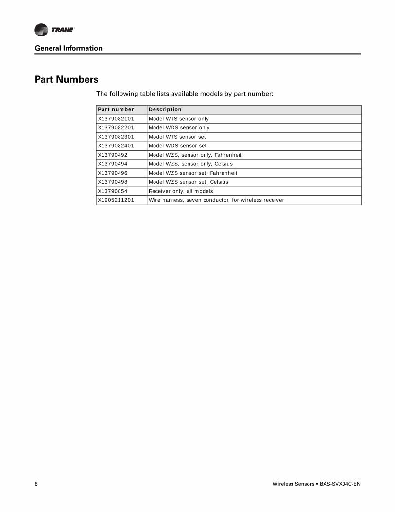
Part Numbers
The following table lists available models by part number:
Part number Description
X1379082101 Model WTS sensor only
X1379082201 Model WDS sensor only
X1379082301 Model WTS sensor set
X1379082401 Model WDS sensor set
X13790492 Model WZS, sensor only, Fahrenheit
X13790494 Model WZS, sensor only, Celsius
X13790496 Model WZS sensor set, Fahrenheit
X13790498 Model WZS sensor set, Celsius
X13790854 Receiver only, all models
X1905211201 Wire harness, seven conductor, for wireless receiver

BAS-SVX04C-EN • Wireless Sensors 9
General Information
Dimensions
The following illustration provides specific dimension details. The dimensions are the same for all models.
2.9 in (73.5 cm)1.08 in (27.5 mm)
4.68 in (118.9 mm)
1.45 in (36.8 mm)
0.63 in (15.9 mm)
0.31 in (8 mm)
0.12 in (3 mm)
TYP R.07 in (R1.9) mm)
3.39 in (86 mm)
2.48 in (63 mm)
2.62 in (66.5 mm)
TYP 0.24 in (6 mm)

10 Wireless Sensors • BAS-SVX04C-EN
Pre-Installation
This section provides the following pre-installation information:
• Location considerations
• Height requirements
• Mounting surfaces
• Address settings
Location Considerations
Placement of the sensor and the receiver is critical to proper operation. For most installations, barriers limit proper radio signal strength more than distance. For best radio transmission range and reliability, mount the receiver and sensor in line of sight. Where this is not possible, try to minimize the number of barriers between the pair of devices. In general, sheetrock walls and ceiling tiles offer little restriction to the transmission of the radio signal throughout the building.
The transmission range for the sensor is as follows:
• Open range: 2,500 ft (762 m) (packet error rate = 2%)
• Usable range: 200 ft (61 m)
• Typical range: 75 ft (23 m)
Receiver
When selecting a receiver location, avoid the following:
• Locations that are outside the operating temperature and humidity range (refer to “Specifications,” p. 47)
• Metal barriers between the receiver and the sensor (for example, plastered walls with metal lathe or metal roof decks)
• Thick, solid concrete walls between the receiver and the sensor
• Placing the receiver inside metal enclosures
• Mounting on rooftop without a careful site evaluation and confirmation
Sensor
When selecting a sensor location, avoid the following:
• Areas of direct sunlight
• Areas in the direct airstream of air diffusers
• Exterior walls and other walls that have a temperature differential between the two sides
• Areas that are close to heat sources such as sunlight, appliances, concealed pipes, chimneys, or other heat-generating equipment
• Drafty areas
• Dead spots behind doors, projection screens, or corners
• Walls that are subject to high vibration
• Areas with high humidity

BAS-SVX04C-EN • Wireless Sensors 11
Pre-Installation
• High traffic areas (to reduce accidental damage or tampering)
• Metal barriers between the receiver and the sensor (for example, plastered walls with metal lathe or metal roof decks)
• Thick, solid concrete walls between the receiver and the sensor
• Placing the sensor inside metal enclosures
Height Requirements
It is recommended that you mount the back plate a maximum distance of 54 inches above the floor. If a parallel approach by a person in a wheelchair is required, reduce the maximum height to 48 inches.
Note: Consult section 4.27.3 of the 2002 ADA (Americans with Disability Act) guideline, and local building codes, for further details regarding wheelchair requirements.
Mounting Surfaces
Using the hardware provided, mount the back plate of the receiver and the sensor to a flat surface such as sheetrock or plaster, or an electrical junction box. The sensor must be mounted plumb for accurate temperature control and to ensure proper air movement through the sensor.
• Receivers: Use the included hardware.
• Sensors:
– If mounting onto sheetrock or plaster, use the plastic threaded anchors (pre-drilling holes is not usually necessary) and the two M3.5 x 20 mm mounting screws.
– For mounting onto an electrical junction box, use the two 6-32 x 3/4 in. screws.
Address Setting
The process of establishing communication between a receiver and sensor is referred to as association. The following limitations apply:
• Each associated receiver/sensor set that communicates within the reception range of the wireless system must have a unique address.
• It is not possible to associate more than one sensor to a receiver, nor is it possible to associate more than one receiver to a sensor.
To associate a receiver and sensor, the two devices must have their rotary address switches set to the same address.
Important: Set the addresses before applying power to the receiver and before removing the insulation strip (Figure 1, p. 12) from the sensor.
12 Wireless Sensors • BAS-SVX04C-EN
Pre-Installation
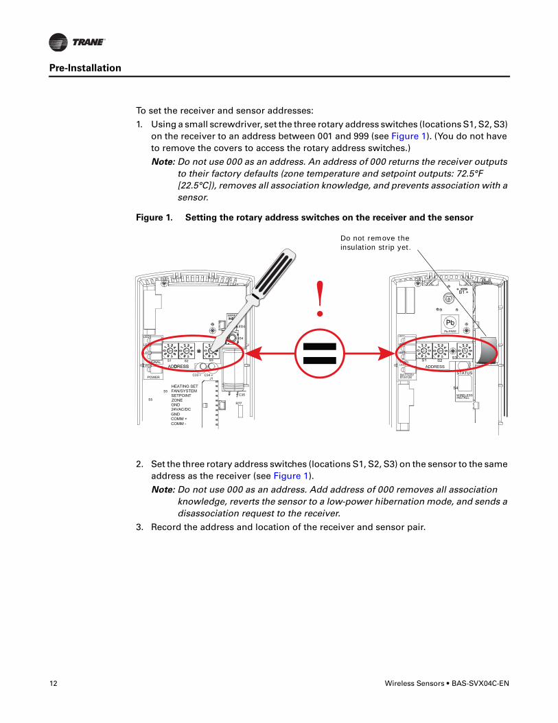
To set the receiver and sensor addresses:
1. Using a small screwdriver, set the three rotary address switches (locations S1, S2, S3) on the receiver to an address between 001 and 999 (see Figure 1). (You do not have to remove the covers to access the rotary address switches.)
Note: Do not use 000 as an address. An address of 000 returns the receiver outputs to their factory defaults (zone temperature and setpoint outputs: 72.5°F [22.5°C]), removes all association knowledge, and prevents association with a sensor.
2. Set the three rotary address switches (locations S1, S2, S3) on the sensor to the same address as the receiver (see Figure 1).
Note: Do not use 000 as an address. Add address of 000 removes all association knowledge, reverts the sensor to a low-power hibernation mode, and sends a disassociation request to the receiver.
3. Record the address and location of the receiver and sensor pair.
Figure 1. Setting the rotary address switches on the receiver and the sensor
S5
GND
R77
C35
S1 S2
C33
LED4
S4
S5
S3
LED1
LED2
LED3
LED5
C34J1
COMM -
24VAC/DC
SETPOINT
HEATING SET
SIGNAL
POWER
ADDDRESS
FAN/SYSTEM
ZONE
COMM +
INSTALLWIRELESS
GND
! B1 +
INSTALLWIRELESS
S4
S3S2S1
ADDRESS
STATUSBATTERY
LED5SIGNAL
LED3
LED2
LED1
PbPb-FREE
STATUS
LED4
L
TALLLESS
L
TAALE
Do not remove the insulation strip yet.
BAS-SVX04C-EN • Wireless Sensors 13
Installation
This section provides step-by-step installation instructions. Read through the pre-installation information before proceeding with installation.
Important: It is recommended that you install the sensor set in the order presented in this section.
Mounting the Receiver Back Plate
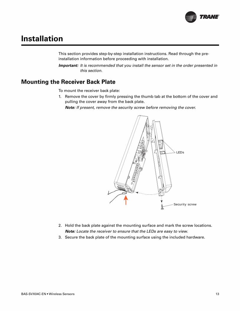
To mount the receiver back plate:
1. Remove the cover by firmly pressing the thumb tab at the bottom of the cover and pulling the cover away from the back plate.
Note: If present, remove the security screw before removing the cover.
2. Hold the back plate against the mounting surface and mark the screw locations.
Note: Locate the receiver to ensure that the LEDs are easy to view.
3. Secure the back plate of the mounting surface using the included hardware.
LEDs
Security screw

14 Wireless Sensors • BAS-SVX04C-EN
Installation
Wiring the Receiver to the Unit Controller
Power requirements and wiring instructions for the receiver are described in this section.
Power Requirements
The required power for the receiver is 24 Vac or 24 Vdc and less than 1 VA. The receiver is designed to be powered by the host unit controller. A dedicated transformer to power the receiver is seldom necessary and is not recommended. It should be used only when the host transformer does not have enough volt-ampere (VA) capacity to power the receiver (see “Specifications,” p. 47 for receiver power consumption).
Wiring diagrams for single transformer wiring and multiple transformer wiring are located in “Appendix A: Wiring Diagrams,” p. 48.
Wiring Procedure
�WARNING
Hazardous voltage!
Disconnect all electric power, including remote disconnects before servicing. Follow
proper lockout/tagout procedures to ensure the power cannot be inadvertently
energized. Failure to disconnect power before servicing could result in death or serious
injury.
NOTICE
Equipment damage!
Applying excessive voltage to the receiver module will permanently damage it.
To wire the receiver to the unit controller:
1. Shut off power to the unit controller to which you are wiring the receiver.
2. Connect the wiring harness (provided) to the receiver (Figure 2, p. 15).
3. Route the wires from the receiver to the unit controller through either:
a. The opening at the back of the back plate (see Figure 3, p. 16 for an example).
b. The hole in the bottom of the cover (see Figure 4, p. 16 for an example).
4. Terminate wires at the unit controller. Refer to Table 1, p. 15 and Figure 2, p. 15 to determine which wires to use and where to terminate them on the controller.
Notes:
• To maintain agency compliance, ensure that length of the wiring harness is no more than 3 m.
• Adaptors are provided, which allow connecting multiple wires to the power terminals of the host unit controller (see Figure 3 and Figure 4, p. 16.
• An anti-short bushing is provided; use it to prevent the wire from shorting out if the steel penetrates the wiring harness (see Figure 4, p. 16).
5. Trim off any unused terminals. Insulate exposed wire with tape or a wire nut.

BAS-SVX04C-EN • Wireless Sensors 15
Installation
Table 1. Wiring harness: Wire identification
Wire label Color Function
HEATING SET Brown Space temperature heating setpoint (WDS only)
FAN SYSTEM Green Fan and system control (WDS only)
SETPOINT Red Space temperature setpoint (WDS and WZS only)
ZONE White Zone temperature
GND-SIGNAL Black Ground for setpoint and zone signal
24VAC/DC Blue 24 Vac/Vdc power
GND-POWER Yellow Ground for 24 Vac/dc
Figure 2. Wiring harness
Connect wiring harness to receiver

16 Wireless Sensors • BAS-SVX04C-EN
Installation
Figure 3. Wiring a receiver to a unit controller through the opening in the back of the receiver back plate
Figure 4. Wiring a receiver to a unit controller through the bottom slot in receiver cover

BAS-SVX04C-EN • Wireless Sensors 17
Installation
Replacing the Receiver Cover
To replace the cover:
1. Hook the cover over the top of the back plate. Apply light pressure to the bottom of the cover until it snaps in place.
2. Install the security screw into the bottom of the cover.
Applying Power to the Receiver
Restore power to the UCM. Observe LED5 on the receiver; it will light and stay constantly On when 24 V power is normal.
Security screw
LED5 stays constantly On after applying power to the receiver

18 Wireless Sensors • BAS-SVX04C-EN
Installation
Observing the Receiver for Readiness to Associate
After initial power up, the receiver conducts a channel scan for 20 seconds. During this time, the receiver selects from 16 available channels the clearest channel on which to operate. LED1, LED2, and LED3 flash rapidly in succession (round-robin style) while the channel scan is in progress, as shown in part 1 of the illustration.
Important: Do not attempt association (leave the insulation strip in place) until the channel scan is finished.
After the channel scan is finished, LED3 begins blinking (one-blink pattern) to show that the receiver is ready to be associated with a sensor. See part 2 of the illustration.
21
LED3
0
20
Sec.

BAS-SVX04C-EN • Wireless Sensors 19
Installation
Associating the Sensor to the Receiver
To associate the sensor to the receiver:
1. Remove the sensor cover by firmly pressing the thumb tab at the bottom of the cover and pulling the cover away from the back plate.
2. Verify that the sensor is set to the same address as the receiver it is to be associated with.
3. Power the sensor by removing the insulation strip from between the two batteries.
Association is automatically initiated between the sensor and the receiver. When LED3 on the receiver stops blinking, association has been established.
If the first association attempt is unsuccessful, the sensor automatically re-attempts association with the receiver every 10 minutes.
Note: An associated sensor that has lost communication with the receiver will transmit an association request every 50 minutes. You can manually initiate association (see “Manual Association,” p. 41”).

20 Wireless Sensors • BAS-SVX04C-EN
Installation
Testing Signal Strength and Battery Status
To verify that the association process was successful and that the batteries have adequate charge:
1. Firmly press and release the Test button on the bottom of the sensor (as illustrated below).
2. For models WTS and WZS, view LED1, LED2, and LED3 to determine the signal strength. View LED5 to determine the battery status. (See the illustration for model WTS and WZS sensors.)
Note: The LEDs will turn Off after 5 seconds to conserve battery strength.
For model WDS, determine the signal strength and battery status by viewing the symbols on the sensor display. (See the illustration for model WDS sensors.)
3. Record the results in your commissioning statement.
Note: For more information, see “Testing Signal Strength,” p. 37 and “Testing Battery Status,” p. 38.
LED1LED2LED3
LED5
Model WTS and WZS sensors Model WDS sensors
Test button
Push firmly, then release
Push firmly, then release
Test button

BAS-SVX04C-EN • Wireless Sensors 21
Installation
Mounting the Sensor Back Plate
To mount the sensor back plate:
1. Hold the back plate against the mounting surface and mark the screw locations.
2. Secure the back plate against the mounting surface using included hardware.
The figure shows an example of mounting the back plate of the sensor into sheetrock or plaster.

22 Wireless Sensors • BAS-SVX04C-EN
Installation
Configuring the Wireless Sensor (Model WDS only)
The configuration of the sensor determines which system features can be accessed and changes can be made by the tenant (for example, changes to cooling/heating mode, setpoint, or fan speed. Verify system and associated unit features before configuring the sensor.
The building owner or operator may choose to limit tenant access to certain features. This can be done through configuration. Or, if a sensor is configured to match all control capabilities of the building automation system, the locking feature can be used to restrict the tenant from making changes.
Configuration Procedure
To configure settings on the model WDS sensor, follow this procedure in the order presented.
1. Press the configuration button for 3 seconds.
The display will change to configuration mode. When the sensor is in configuration mode, a wrench symbol appears on the display and the menus are separated by lines, as illustrated below.
Configuration button

BAS-SVX04C-EN • Wireless Sensors 23
Installation
1. Press the center button on the keypad to begin the configuration process.
2. Configure the sensor options in the order shown in the table.
• Press or to scroll to the next selection (as illustrated).
• Press or to move to the next menu (as illustrated).
Center button
Setting Configuration options
Temperature• Choose Fahrenheit or
Celsius• Choose the degree
resolution (whole degrees, half degrees, or tenths of degrees).
Setpoint
Deadband (available for dual setpoint system only)
Note: Deadband refers to the minimum difference between the heating and cooling setpoints.
Systema) Single setpoint
. . ....
dual setpointnosetpoint
singlesetpoint
.
heat/cool setpoint offset(1.8˚F – 10.8˚F, 1˚C – 6˚C)

24 Wireless Sensors • BAS-SVX04C-EN
Installation
System (continued)b) Dual setpoint
c) No setpoint
Fan
Note: Not all fan options are available for all systems.
Occupancy (timed override)
Setting Configuration options
emergency heat/heat/cool/off
heat/cool/auto/off
emergency heat/heat/cool/auto/off
no systemoptions enabled
auto/off/lowmed/high
auto/off/low/high
auto/off
off/high (on) off/low/high off/low/med/high
no fan optionsenabled
auto/high (on)
BAS-SVX04C-EN • Wireless Sensors 25
Installation
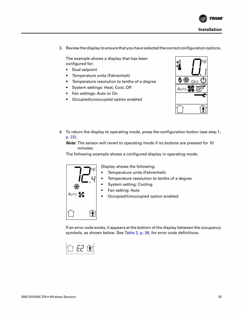
3. Review the display to ensure that you have selected the correct configuration options.
4. To return the display to operating mode, press the configuration button (see step 1, p. 22).
Note: The sensor will revert to operating mode if no buttons are pressed for 10 minutes.
The following example shows a configured display in operating mode.
If an error code exists, it appears at the bottom of the display between the occupancy symbols, as shown below. See Table 2, p. 36, for error code definitions.
The example shows a display that has been configured for:
• Dual setpoint
• Temperature units (Fahrenheit)
• Temperature resolution to tenths of a degree
• System settings: Heat, Cool, Off
• Fan settings: Auto or On
• Occupied/unoccupied option enabled
Display shows the following:
• Temperature units (Fahrenheit)
• Temperature resolution to tenths of a degree
• System setting: Cooling
• Fan setting: Auto
• Occupied/Unoccupied option enabled

26 Wireless Sensors • BAS-SVX04C-EN
Installation
Optional Features
Displaying Setpoint or Temperature
You can configure the sensor to display either the temperature (default) or setpoint. To select either option:
1. Verify that the sensor is in operating mode and at the home screen.
2. Press the up and down arrows for 3 seconds. The arrow indicates setpoint display, as shown in the illustration.
Locking or Unlocking Settings
You can lock or unlock the setpoint, system, or fan setting to prevent changes.
To lock or unlock a setting:
1. Verify that the sensor is in operating mode and at the home screen.
2. Choose a setting to lock or unlock:
• Select the setpoint by pressing the up or down arrow.
• Select the system menu by pressing the center button. Use the left or right arrow to choose the setting.
• From the system menu press the down arrow to select the fan menu. Use the left or right arrow to choose the setting.
Arrow indicates setpoint is shown on display
Setpoint
System menu
Fan menu

BAS-SVX04C-EN • Wireless Sensors 27
Installation
3. Press the left and right arrows for 4 seconds.
Note: If you try to access a feature that is locked, the locked symbol will appear on the display. If you press a keypad button to try change a locked setting, the locked symbol will flash.
Replacing the Sensor Cover
To replace the cover:
1. Hook the cover over the top of the back plate. Apply light pressure to the bottom of the cover until it snaps in place.
2. Install the security screw into the bottom of the cover (if desired).
Security screw

28 Wireless Sensors • BAS-SVX04C-EN
Operation
This section describes sensor operations.
Temporary Occupancy (Timed Override)
Temporary occupancy (timed override) is available on models WDS and WZS. Temporary occupancy is selected for after-business-hours adjustment of temperature setting, fan settings, or heat/cool settings, when the system has changed to unoccupied mode. System control will revert to unoccupied after a pre-determined time period.
Note: Not all systems support the occupancy function.
Model WZS Sensor
The model WZS sensor has Occupied and Unoccupied buttons for requesting and canceling temporary occupancy.
To request temporary occupancy, press the Occupied button (Figure 5) for 0.2–6 seconds. The following occurs:
• Space temperature output is driven to 10 Ω (nominal).
• The output generates for 4 seconds.
To cancel temporary occupancy, press the Unoccupied button (Figure 5) for 0.2–6 seconds. The following occurs:
• Space temperature output is driven to 1330 Ω (nominal).
• The output generates for 4 seconds.
Model WDS Sensor
To request and cancel temporary occupancy on a model WDS sensor, see “Requesting Temporary Occupancy,” p. 34.
Figure 5. WZS sensor: Locations of occupied button and unoccupied buttons
Occupied button
Unoccupied button
BAS-SVX04C-EN • Wireless Sensors 29
Operation
Service Pin Request
Model WZS and WDS sensors can communicate a service pin request to their associated receivers.
Model WZS Sensor
To initiate a service pin request, press the Occupied button (Figure 5, p. 28) for 10–25 seconds. The following occurs:
• Space temperature output is driven to 10 Ω (nominal).
• The output generates for 15 seconds.
Model WDS Sensor
To initiate a service pin request, the sensor must be configured to support occupancy and must be in operating mode (see “Configuring the Wireless Sensor (Model WDS only),” p. 22).
To initiate a service pin request:
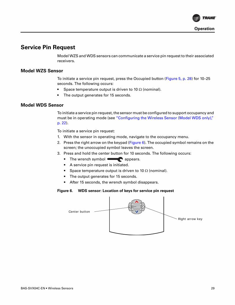
1. With the sensor in operating mode, navigate to the occupancy menu.
2. Press the right arrow on the keypad (Figure 6). The occupied symbol remains on the screen; the unoccupied symbol leaves the screen.
3. Press and hold the center button for 10 seconds. The following occurs:
• The wrench symbol appears.
• A service pin request is initiated.
• Space temperature output is driven to 10 Ω (nominal).
• The output generates for 15 seconds.
• After 15 seconds, the wrench symbol disappears.
Figure 6. WDS sensor: Location of keys for service pin request
Center button
Right arrow key
30 Wireless Sensors • BAS-SVX04C-EN
Operation
Star(*)/Double Star(**) Function
The star/double star function is available on models WDS and WZS. Consult the appropriate unit controller documentation for information about this function.
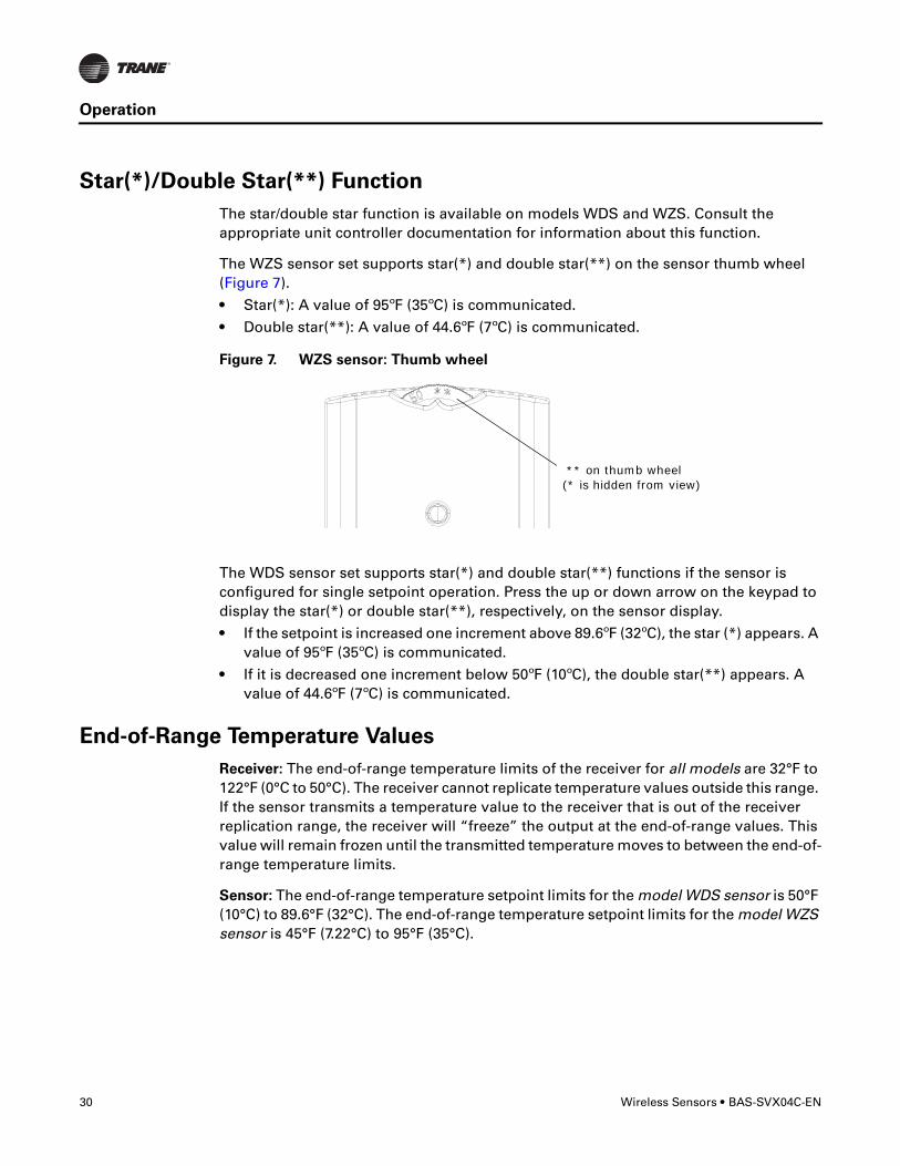
The WZS sensor set supports star(*) and double star(**) on the sensor thumb wheel (Figure 7).
• Star(*): A value of 95ºF (35ºC) is communicated.
• Double star(**): A value of 44.6ºF (7ºC) is communicated.
The WDS sensor set supports star(*) and double star(**) functions if the sensor is configured for single setpoint operation. Press the up or down arrow on the keypad to display the star(*) or double star(**), respectively, on the sensor display.
• If the setpoint is increased one increment above 89.6ºF (32ºC), the star (*) appears. A value of 95ºF (35ºC) is communicated.
• If it is decreased one increment below 50ºF (10ºC), the double star(**) appears. A value of 44.6ºF (7ºC) is communicated.
End-of-Range Temperature Values
Receiver: The end-of-range temperature limits of the receiver for all models are 32°F to 122°F (0°C to 50°C). The receiver cannot replicate temperature values outside this range. If the sensor transmits a temperature value to the receiver that is out of the receiver replication range, the receiver will “freeze” the output at the end-of-range values. This value will remain frozen until the transmitted temperature moves to between the end-of-range temperature limits.
Sensor: The end-of-range temperature setpoint limits for the model WDS sensor is 50°F (10°C) to 89.6°F (32°C). The end-of-range temperature setpoint limits for the model WZS sensor is 45°F (7.22°C) to 95°F (35°C).
Figure 7. WZS sensor: Thumb wheel
** on thumb wheel (* is hidden from view)

BAS-SVX04C-EN • Wireless Sensors 31
Operation
Receiver Power-up Sequence
When power is applied to the receiver, one of the following sequences occurs. The sequence is dependent on the address setting and the association status of the receiver.
Address set to 000 and receiver is not associated with a sensor
• LED5 is constantly On, indicating power is applied and the receiver is functional.
• All models: Zone temperature and cooling setpoint default to 72.5°F (22.5°C). WDS only: The heating setpoint defaults to 70.5°F (21.4°C) and the fan/system output will be 2230 Ω (see “Output Values—Failure and Default Modes of Operation,” p. 44).
• Status LED3 will display a 2-blink pattern diagnostic (Table 3, p. 36).
Address set from 001 to 999 and receiver is not associated with a sensor
• LED5 is constantly On, indicating power is applied and the receiver is functional.
• All models: Zone temperature and cooling setpoint default to 72.5°F (22.5°C). WDS only: The heating setpoint defaults to 70.5°F (21.4°C) and the fan/system output will be 2230 Ω (see “Output Values—Failure and Default Modes of Operation,” p. 44).
• The receiver conducts an energy scan for 20 seconds to determine the clearest channel on which to operate.
• LED3 flashes On every 2 seconds when it is ready to accept a sensor association request. When an association request is made by a sensor, the receiver instructs the sensor on which power level to operate. Then the receiver and sensor begin operation at the appropriate channel and power level (see “Observing the Receiver for Readiness to Associate,” p. 18).
Address set from 001 to 999 (and not changed since most recent power-up)
and receiver is associated with a sensor
• LED5 is constantly On, indicating power is applied and the receiver is functional.
• Zone temperature and setpoint default to 72.5°F (22.5°C). WDS only: Heating setpoint defaults to 70.5°F (21.4°C), Fan = Auto, System = Off.
• The receiver waits for a broadcast transmission from its associated sensor. When a transmission is received, the receiver positions its zone temperature and setpoint outputs appropriately.
• If the receiver does not receive a communicated signal from its associated sensor within 35 minutes, zone temperature and setpoint outputs fail, generating a unit controller alarm (see “Output Values—Failure and Default Modes of Operation,” p. 44).
Note: Once a receiver communicates to a WTS sensor, the receiver disables (opens) its zone setpoint output indefinitely.

32 Wireless Sensors • BAS-SVX04C-EN
Operation
Sensor Transmission Time and Temperature Variables
Sensor transition time variables are as follows:
• The maximum time between sensor temperature transmissions is 15 minutes.
• The minimum time between sensor temperature transmissions is 30 seconds.
• The minimum time for transmitting temperature setpoint changes is 10 seconds.
Note: If a sensor transmits a message to the receiver and the receiver does not reply, the sensor will retransmit the message to the receiver every 30 seconds until communication to the receiver is re-established.
Sensor temperature time variables are as follows:
• The minimum change in zone temperature required to force a sensor transmission is:
– 0.2°F (0.11°C) when the temperature range is between 60°F (15.6°C) and 80°F (26.7°C)
– 0.5°F (0.28°C) when the temperature range is between 32°F (0°C) and 60°F (15.6°C) or between 80°F (26.7°C) and 122°F (50°C))
• The minimum change in temperature setpoint required to force a sensor transmission is:
– 1°F (0.56°C) for a model WZS sensor
– 0.1°F for model WZS sensor
– 0.1°C for a model WDS sensor
Operating Mode (Model WDS)
This section describes how to operate the Trane wireless sensor, model WDS. Figure 8 shows an example of a model WDS that has been configured and is in operating mode.
Figure 8. Wireless sensor (model WDS) in operating mode
.
Keypad
Test button
Test symbols (appear only when Test button is pushed
Occupancy indicator/Error code
Temperature
System settings
Fan settings
BAS-SVX04C-EN • Wireless Sensors 33
Operation
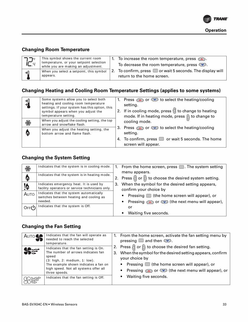
Changing Room Temperature
Changing Heating and Cooling Room Temperature Settings (applies to some systems)
Changing the System Setting
Changing the Fan Setting
This symbol shows the current room temperature, or your setpoint selection while you are making an adjustment.
1. To increase the room temperature, press .
To decrease the room temperature, press .
2. To confirm, press or wait 5 seconds. The display will return to the home screen.
When you select a setpoint, this symbol appears.
Some systems allow you to select both heating and cooling room temperature settings. If your system has this option, this symbol appears when you adjust the temperature setting.
1. Press or to select the heating/cooling setting.
2. If in cooling mode, press to change to heating mode. If in heating mode, press to change to cooling mode.
3. Press or to select the heating/cooling setting.
4. To confirm, press or wait 5 seconds. The home screen will appear.
When you adjust the cooling setting, the top arrow and snowflake flash.When you adjust the heating setting, the bottom arrow and flame flash.
Indicates that the system is in cooling mode. 1. From the home screen, press . The system setting menu appears.
2. Press or to choose the desired system setting.
3. When the symbol for the desired setting appears, confirm your choice by
• Pressing (the home screen will appear), or
• Pressing or (the next menu will appear), or
• Waiting five seconds.
Indicates that the system is in heating mode.
Indicates emergency heat. It is used by facility operators or service technicians only.Indicates that the system automatically switches between heating and cooling as needed.Indicates that the system is Off.
Indicates that the fan will operate as needed to reach the selected temperature.
1. From the home screen, activate the fan setting menu by pressing and then .
2. Press or to choose the desired fan setting.
3. When the symbol for the desired setting appears, confirm your choice by
• Pressing (the home screen will appear), or
• Pressing or (the next menu will appear), or
• Waiting five seconds.
Indicates that the fan setting is On. The number of arrows indicates fan speed (3: high, 2: medium, 1: low). The example shown indicates a fan on high speed. Not all systems offer all three speeds.Indicates that the fan setting is Off.
.

34 Wireless Sensors • BAS-SVX04C-EN
Operation
Requesting Temporary Occupancy
Error codes
Lock Symbol
Testing Signal Strength
Testing Battery Status
Select to request occupancy
• If you need heating or cooling after normal business hours, you can “request” temporary occupancy by pressing and holding it for 2 seconds. The occupied symbol remains on the screen and the unoccupied symbol disappears. After 30 seconds, unoccupied symbol will re-appear.
• To cancel temporary occupancy, press and hold for 2 seconds. The unoccupied symbol will remain on the screen and the occupied symbol will disappear. After 30 seconds the occupied symbol will re-appear.
Select to cancel occupancy
Indicates an error code If an error code (E0–E7) is displayed, technical assistance may be required.
Indicates that a setting is locked
The lock symbol appears if you try to adjust a setting that cannot be changed.
Indicates excellent signal strength
Indicates satisfactory signal strength
Indicates poor signal strength
Press the Test button to display the signal strength symbols.
Indicates full battery power
Indicates 50% of battery life left.
Indicates 25% of battery life left. Replace batteries.Flashing symbol
indicates that approximately 14 days of operation remain.
Press the Test button to display the battery status symbols.
Use only UL-listed non-rechargeable 1.5 V lithium AA batteries (Trane p/n X13770035010 or equivalent).

BAS-SVX04C-EN • Wireless Sensors 35
Maintenance and Troubleshooting
This section describes features of the receiver and sensor that are to be used for maintenance and troubleshooting.
Locations of LEDs, Test button, Test Symbols, and Error Codes
The receiver for all models has four LEDs: LED1, LED2, LED3, and LED5. Figure 9 shows their locations.
The sensor for models WTS and WZS have four LEDs: LED1, LED2, LED3, and LED5. The sensor for model WDS has test symbols and error codes that appear on the display. All three sensor models have a Test button. Figure 10 shows their locations.
Figure 9. LED locations on the receiver
LED1LED2
LED3
LED5
Figure 10. LED, Test button, and symbol locations on the sensor
.
Test symbols
Error code
Test button
LED1LED2LED3
LED5
Test button
WTZ, WZS sensor WDS sensor

36 Wireless Sensors • BAS-SVX04C-EN
Maintenance and Troubleshooting
Diagnostics
LED1, LED2, and LED3, located on the sensor of models WTS and WZS, respond to diagnostics by exhibiting specific blinking patterns. View their response by pressing the Test button. (See Table 2.)
Error codes appear on the display of the model WDS sensor when diagnostics occur. (See Table 2.)
LED1, LED2, and LED3, located on the receiver of all models, respond to diagnostics by exhibiting specific blinking patterns. They respond independently of any user action. (See Table 3.)
Table 2. Diagnostics on the sensor
LED state when Test button is pressed (WTS, WZS sensors)
Error code (WDS sensor display) Indicates...
N/A E0, E5, E7 Sensor failure• Replace sensor
LED1: OffLED2: OffLED3(a): 1-blink pattern repeated 3 times
E1 Disassociated• Sensor is not associated with a receiver.
LED1: OffLED2: OffLED3(a): 2-blink pattern repeated 3 times
E2 Address set to 000• Address not set to between 001–999.
LED1: OffLED2: OffLED3(a): 3-blink pattern repeated 3 times
E3 Software error• Replace sensor
LED1: OffLED2: OffLED3(a): 4-blink pattern repeated 3 times
E4 Input voltage too high• No RF transmission is permitted with an input
battery voltage greater than 3.9 V.
(a) Blink pattern is On for 1/4 s, Off for 1/4 s, with 2 s Off between repetitions.
Table 3. Diagnostics on the receiver
LED state Indicates...
LED1: OffLED2: OffLED3: 1-blink pattern repeated continuously(a)
Disassociated• Receiver is not associated, waiting for a sensor.• Receiver lost communication with sensor.• Receiver has no devices on its wireless personal area network.• Association with a device has been manually removed.
LED1: OffLED2: OffLED3: 2-blink pattern repeated continuously(a)
Address set to 000• Address not set to between 001–999.
LED1: OffLED2: OffLED3: 3-blink pattern repeated continuously(a)
Not configured• Receiver configuration properties not properly set (defective receiver).
(a) Blink pattern is On for 1/4 s, Off for 1/4 s, with 2 s Off between repetitions.

BAS-SVX04C-EN • Wireless Sensors 37
Maintenance and Troubleshooting
Testing Signal Strength
To initiate a signal strength test, push the Test button on the sensor (see location of Test button in Figure 10, p. 35).
• Models WTS, WZS: LED1, LED2, and LED3 respond by indicating signal strength. You can view them on the sensor (Table 4) and the receiver (Table 5, p. 38).
• Model WDS: Test symbols on the sensor display indicate signal strength (Table 4). LED1, LED2, and LED3, on the receiver, respond by indicating signal strength (Table 5, p. 38).
Table 4. Observing signal strength on the sensor
User action LED state (WTS, WZS sensors)Symbol (WDS sensor display) Indicates...
None LED1: OffLED2: OffLED3: Off
No Test symbols appear
Normal state • No Test button press.
Press Test button on the sensor
LED1: OffLED2: OffLED3: Off
Associated; no communication with receiver• Associated, but no signal from the receiver after
pressing Test button.
LED1: OnLED2: OnLED3: OnDisplays for 5 seconds, then constantly Off
Excellent signal strength• Good signal margin for reliable communication.
LED1: OffLED2: OnLED3: OnDisplays for 5 seconds, then constantly Off
Satisfactory signal strength• Adequate signal strength for reliable communication.• Moving sensor or receiver may improve signal
strength.• Increased channel switching may reduce battery
life.
LED1: OffLED2: OffLED3: OnDisplays for 5 seconds, then constantly Off
Poor signal strength• Unreliable communication.• Strongly recommend moving the sensor or receiver
to a better location.

38 Wireless Sensors • BAS-SVX04C-EN
Maintenance and Troubleshooting
Testing Battery Status
Initiate a battery status test as follows:
• On models WTS and WZS, push the Test button on the sensor (see location on Figure 10, p. 35). LED5 on the sensor responds by indicating the level of battery strength, as shown in Table 6.
• On model WDS, push the Test button on the sensor (see location on Figure 10, p. 35). In response, a battery test symbol appears on the display. The symbol shown indicates battery life expectancy (see Table 7, p. 39).
Table 5. Observing signal strength on the receiver
User action LED state (receiver, all models) Indicates...
None LED1: OffLED2: OffLED3: Off
Normal state • No Test button press.
Press Test button on the sensor
LED1: OnLED2: OnLED3: OnDisplays for 5 seconds, then constantly Off
Excellent signal strength• Good signal margin for reliable communication.
LED1: OffLED2: OnLED3: OnDisplays for 5 seconds, then constantly Off
Satisfactory signal strength• Adequate signal strength for reliable communication.• Moving sensor or receiver may improve signal strength.• Increased channel switching may reduce battery life.
LED1: OffLED2: OffLED3: OnDisplays for 5 seconds, then constantly Off
Poor signal strength• Unreliable communication• Strongly recommend moving the sensor or receiver to a
better location
Table 6. Battery status: LED5 on model WTS and WZS sensors
User action LED state (WTS, WZS) Indicates...
Press Test button
Solid green for 5 seconds Battery is adequate for proper operation.
Solid red for 5 seconds 25% battery life left. Batteries should be replaced.
No light Batteries life expired or not installed properly, or sensor is defective.
None Blinking red: 1-blink pattern(a) repeated 5 times. Cycle repeats every 15 minutes.
Approximately 14 days of operation remain before the battery is too weak to power the sensor.
(a) Blink pattern is On for 1/4 s, Off for 3/4 s, with 2 s Off between repetitions.

BAS-SVX04C-EN • Wireless Sensors 39
Maintenance and Troubleshooting
24 V Power Status Indicator
LED5 on the receiver of all models (Figure 9, p. 35) lights and stays constantly On when 24 V power is normal.
Using the Wireless Sensor System to Check Signal Strength on a Site
Follow these steps to check the signal strength on a site:
1. Power up a receiver with a 24 V transformer (user supplied)
2. Associate the sensor to a receiver of the same model intended for the job
3. Place the receiver at the desired location
4. Place or hold the sensor at the desired location
5. Press the Test button (S5) on the sensor and observe the signal strength as indicated by LED1, LED2, and LED3 on models WTS and WZS, and on the display on model WDS (Figure 10, p. 35).
For more information on interpreting the LEDs and the display symbols that indicate signal strength, see “Testing Signal Strength,” p. 37.
Table 7. Battery status: Battery symbol on model WDS sensor display
User action
Battery test symbol Indicates...
Press Test button
Full battery power.
50% battery life left.
25% battery life left. Replace batteries.Flashing symbol indicates that approximately 14 days of operation remain before the battery is too weak to power the sensor.

40 Wireless Sensors • BAS-SVX04C-EN
Maintenance and Troubleshooting
Replacing Sensor Batteries
Sensor battery type, length of life, and installation are addressed in this section.
Battery Type
NOTICE
Equipment Damage!
The batteries are manufactured in a ready-to-use state. They are not designed for
recharging. Recharging can cause battery leakage or, in some cases, can cause the
safety release vent to open.
NOTICE
Equipment Damage!
Do not attempt to hook up the sensor to a power supply. Equipment damage may
result.
Use two non-rechargeable 1.5 V lithium AA batteries in the sensor. To maintain UL rating, use only UL-listed lithium batteries. The sensor ships with Energizer™ L91 batteries already installed. Replacement batteries are available at Trane Service Parts Centers (p/n X13770035010) or other local suppliers.
Battery Life
Battery life is five years under normal conditions. If the sensor is not used for an extended period of time, do one of the following:
• Set the sensor address to 000 to place the sensor into a low-power hibernation mode.
• Remove the batteries
Notes:
• If lithium batteries are temporarily unavailable, alkaline batteries can be used. However, alkaline battery life is very short by comparison.
• The battery life for a model WDS may decrease with extended LCD display activity.
Battery Installation
�WARNING
Prevent Injury!
Batteries can explode or leak and cause burns if installed backwards, disassembled,
charged, or exposed to water, fire, or high temperature.
�WARNING
Prevent Injury!
Keep away from small children. If swallowed, contact your local poison control center
immediately.
BAS-SVX04C-EN • Wireless Sensors 41
Maintenance and Troubleshooting
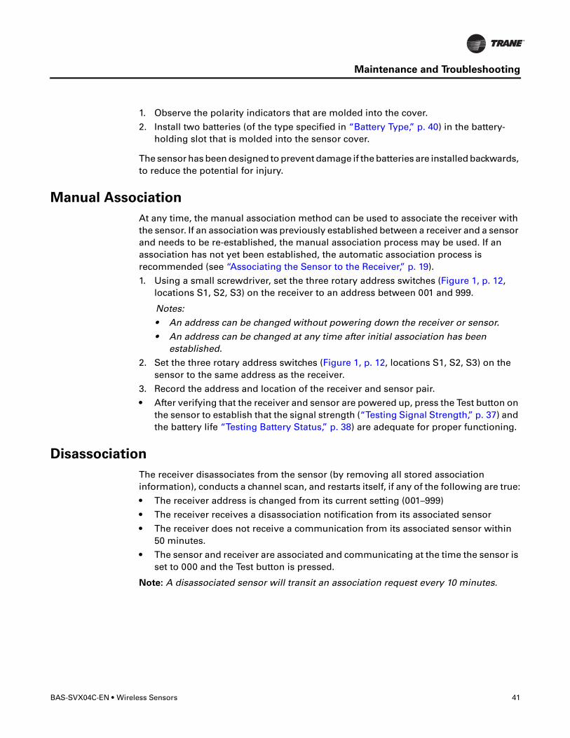
1. Observe the polarity indicators that are molded into the cover.
2. Install two batteries (of the type specified in “Battery Type,” p. 40) in the battery-holding slot that is molded into the sensor cover.
The sensor has been designed to prevent damage if the batteries are installed backwards, to reduce the potential for injury.
Manual Association
At any time, the manual association method can be used to associate the receiver with the sensor. If an association was previously established between a receiver and a sensor and needs to be re-established, the manual association process may be used. If an association has not yet been established, the automatic association process is recommended (see “Associating the Sensor to the Receiver,” p. 19).
1. Using a small screwdriver, set the three rotary address switches (Figure 1, p. 12, locations S1, S2, S3) on the receiver to an address between 001 and 999.
Notes:
• An address can be changed without powering down the receiver or sensor.
• An address can be changed at any time after initial association has been established.
2. Set the three rotary address switches (Figure 1, p. 12, locations S1, S2, S3) on the sensor to the same address as the receiver.
3. Record the address and location of the receiver and sensor pair.
• After verifying that the receiver and sensor are powered up, press the Test button on the sensor to establish that the signal strength (“Testing Signal Strength,” p. 37) and the battery life “Testing Battery Status,” p. 38) are adequate for proper functioning.
Disassociation
The receiver disassociates from the sensor (by removing all stored association information), conducts a channel scan, and restarts itself, if any of the following are true:
• The receiver address is changed from its current setting (001–999)
• The receiver receives a disassociation notification from its associated sensor
• The receiver does not receive a communication from its associated sensor within 50 minutes.
• The sensor and receiver are associated and communicating at the time the sensor is set to 000 and the Test button is pressed.
Note: A disassociated sensor will transit an association request every 10 minutes.
42 Wireless Sensors • BAS-SVX04C-EN
Maintenance and Troubleshooting
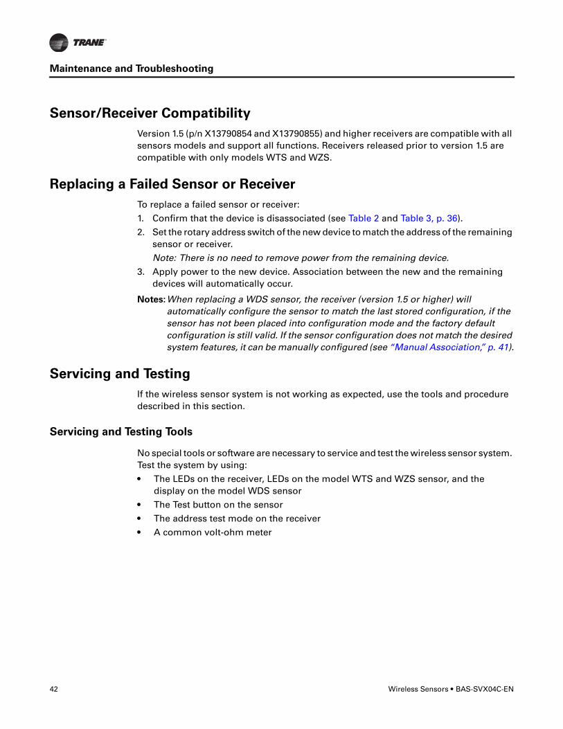
Sensor/Receiver Compatibility
Version 1.5 (p/n X13790854 and X13790855) and higher receivers are compatible with all sensors models and support all functions. Receivers released prior to version 1.5 are compatible with only models WTS and WZS.
Replacing a Failed Sensor or Receiver
To replace a failed sensor or receiver:
1. Confirm that the device is disassociated (see Table 2 and Table 3, p. 36).
2. Set the rotary address switch of the new device to match the address of the remaining sensor or receiver.
Note: There is no need to remove power from the remaining device.
3. Apply power to the new device. Association between the new and the remaining devices will automatically occur.
Notes:When replacing a WDS sensor, the receiver (version 1.5 or higher) will automatically configure the sensor to match the last stored configuration, if the sensor has not been placed into configuration mode and the factory default configuration is still valid. If the sensor configuration does not match the desired system features, it can be manually configured (see “Manual Association,” p. 41).
Servicing and Testing
If the wireless sensor system is not working as expected, use the tools and procedure described in this section.
Servicing and Testing Tools
No special tools or software are necessary to service and test the wireless sensor system. Test the system by using:
• The LEDs on the receiver, LEDs on the model WTS and WZS sensor, and the display on the model WDS sensor
• The Test button on the sensor
• The address test mode on the receiver
• A common volt-ohm meter

BAS-SVX04C-EN • Wireless Sensors 43
Maintenance and Troubleshooting
Procedure for Testing the Wireless Sensor System
If the wireless sensor system is not working as expected:
1. Observe LED5 on the receiver. LED5 is On solid green whenever the receiver is powered.
2. Verify that the receiver is properly grounded. Both the GND-SIGNAL (black) wire and the GND-POWER (yellow) wire must be grounded (see Figure 3, p. 16 or Figure 4, p. 16 for wiring diagrams).
3. Press the Test button on the sensor.
• Models WTS, WZS: LED5 should turn On solid green, indicating proper battery strength. LED1, LED2, and LED3 will indicate signal strength.
Note: When checking signal strength, both LED1 and LED3 on the receiver and sensor illuminate in unison if the sensor and receiver are associated. Use this feature to confirm association.
• Model WDS: Battery life (“Testing Battery Status,” p. 34) and signal strength (“Testing Signal Strength,” p. 34) are indicated on the display.
Procedure for Testing the Receiver
If the receiver is not working as expected:
1. Verify that the receiver is powered.
2. Set the receiver address to 000 to force the zone temperature output and zone temperature setpoint output to their default mode values (see “Output Values—Failure and Default Modes of Operation,” p. 44).
3. Measure the receiver output resistance (see “Measuring Output Resistance,” p. 44).
4. When the test is complete, reset the receiver address to its previous setting.
5. Press the Test button on the sensor to force re-association.
6. Confirm association and communication by noting LED1, LED2, and LED3 as described in “Testing Signal Strength,” p. 37.
Forcing a Sensor to Transmit
To force a wireless sensor to transmit during servicing, press the Test button on the sensor.
Output Power Level
The maximum output power level of a wireless sensor set is controlled by software and restricted by channel of operation and agency requirements per country or region. The sensor has a default maximum power level of 10 mW, but the receiver determines the ultimate output power level of the sensor.

44 Wireless Sensors • BAS-SVX04C-EN
Maintenance and Troubleshooting
Output Values—Failure and Default Modes of Operation
The following table provides output values for failure and default modes of operation, which can be used for troubleshooting.
Measuring Output Resistance
To measure the resistance of receiver outputs for zone temperature and setpoints for all models, and heating setpoint and fan/system for the WDS:
1. Ensure that the GND-SIGNAL (black) wire and the GND-POWER (yellow) wire are grounded to the transformer (see Figure 4, p. 16 or Figure 3, p. 16 for wiring diagrams).
2. Disconnect the ZONE (white) and SETPOINT (RED) wires from the controller. Disconnect the HEAT SETPOINT (brown) and FAN/SYSTEM (green) wires from the controller, if applicable.
3. Measure resistance as follows:
a. All models: Measure between the grounded GND-SIGNAL (black) wire and either the SETPOINT (red) or ZONE (white) wire. Compare resistance measurements to those in Table 8.
b. WDS only: Measure between the grounded GND-SIGNAL (black) wire and the FAN/SYSTEM (green) wire. Compare resistance measurements to those given in Table 9.
Situation
Zone temperature output
Zone setpoint output
Heating setpoint output
Fan/System output
Receiver address = 000 11.17 kΩ, 72.5°F (22.5°C), indefinitely
451 Ω, 72.5°F (22.5°C), indefinitely
501 Ω, 70.5°F (21.4°C), indefinitely
2320 ΩFan = AutoSystem = Off
Receiver address = 001 to 999 and:• Receiver is powered up, but not is associated, or• Receiver has received a disassociation request
from the associated sensor.
11.17 kΩ, 72.5°F (22.5°C) Hold for 15 minutes, then open
451 Ω, 72.5°F (22.5°C), Hold for 15 minutes, then open
501 Ω, 70.5°F (21.4°C), indefinitely
2320 ΩFan = AutoSystem = Off
Receiver address = 001 to 999 and receiver has not received a communication within 35 minutes from the associated sensor.
Open Open Open Open
Receiver has no power. Open Open Open Open
Thermistor in sensor has failed to either open or close.
Open Normal value Normal value N/A
Setpoint potentiometer has failed to either open or close.
Normal value Open Open N/A
BAS-SVX04C-EN • Wireless Sensors 45
Maintenance and Troubleshooting
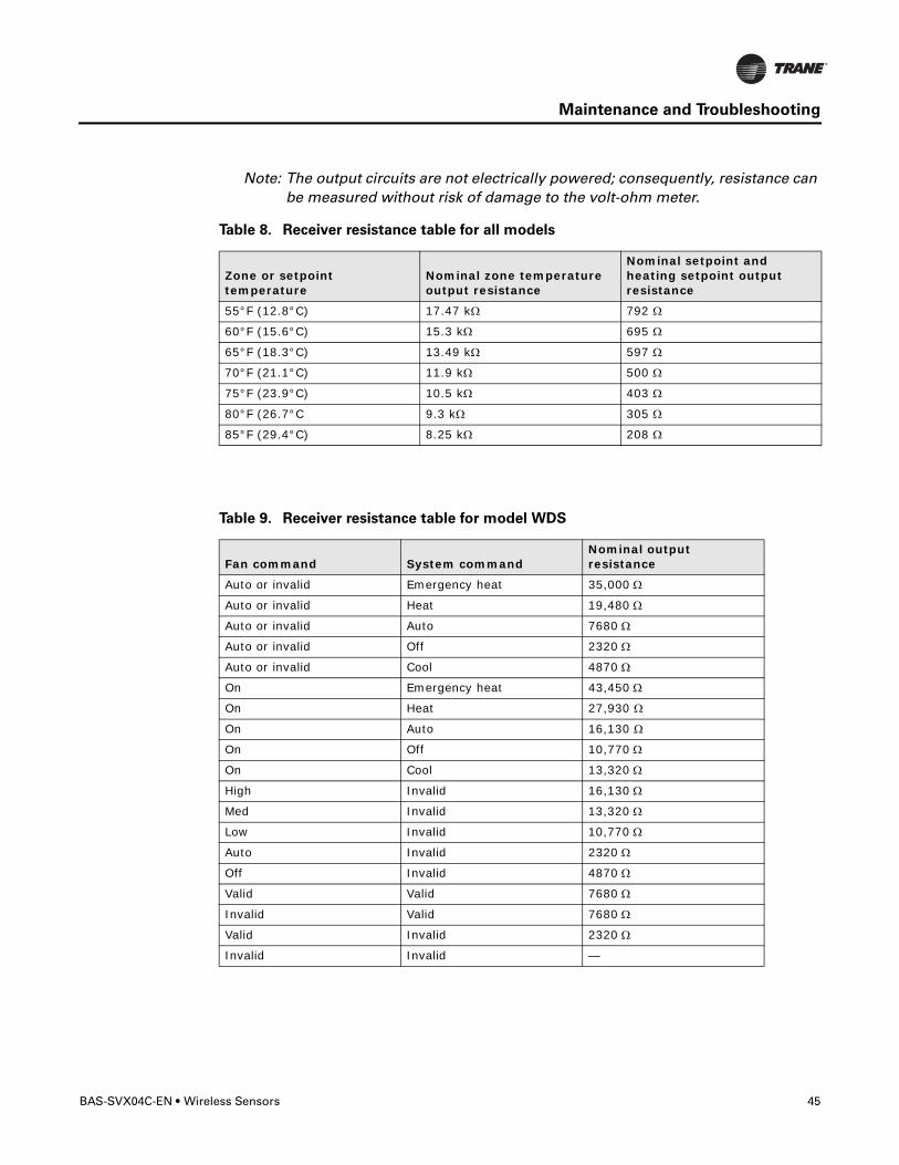
Note: The output circuits are not electrically powered; consequently, resistance can be measured without risk of damage to the volt-ohm meter.
Table 8. Receiver resistance table for all models
Zone or setpoint temperature
Nominal zone temperature output resistance
Nominal setpoint and heating setpoint output resistance
55°F (12.8°C) 17.47 kΩ 792 Ω
60°F (15.6°C) 15.3 kΩ 695 Ω
65°F (18.3°C) 13.49 kΩ 597 Ω
70°F (21.1°C) 11.9 kΩ 500 Ω
75°F (23.9°C) 10.5 kΩ 403 Ω
80°F (26.7°C 9.3 kΩ 305 Ω
85°F (29.4°C) 8.25 kΩ 208 Ω
Table 9. Receiver resistance table for model WDS
Fan command System commandNominal output resistance
Auto or invalid Emergency heat 35,000 Ω
Auto or invalid Heat 19,480 Ω
Auto or invalid Auto 7680 Ω
Auto or invalid Off 2320 Ω
Auto or invalid Cool 4870 Ω
On Emergency heat 43,450 Ω
On Heat 27,930 Ω
On Auto 16,130 Ω
On Off 10,770 Ω
On Cool 13,320 Ω
High Invalid 16,130 Ω
Med Invalid 13,320 Ω
Low Invalid 10,770 Ω
Auto Invalid 2320 Ω
Off Invalid 4870 Ω
Valid Valid 7680 Ω
Invalid Valid 7680 Ω
Valid Invalid 2320 Ω
Invalid Invalid —

46 Wireless Sensors • BAS-SVX04C-EN
Maintenance and Troubleshooting
Cleaning the Sensor
NOTICE
Equipment damage!
Spraying glass cleaner or any other solution directly on the sensor may damage it.
You can clean the sensor by applying glass cleaner to a soft, non-abrasive cloth, and gently wiping the face, including the buttons and LCD display. Use of a pre-moistened towelette designed for lens or screen cleaning is also acceptable.
Avoid inadvertent pressing of the Occupied/Unoccupied buttons on the model WZS sensor or the keypad on the WDS sensor, as this may result in an unwanted timed override or settings change.

BAS-SVX04C-EN • Wireless Sensors 47
Specifications
The following table presents specifications for all models of the wireless sensor sets.
Sensor operating temperature 32 to 122ºF (0 to 50ºC)
Receiver operating temperature -40 to 158ºF (-40 to 70ºC)
Storage temperature -40 to 185ºF (-40 to 85°C)
Storage and operating humidity range 5% to 95%, non-condensing
Accuracy 0.5 °F over a range of 55 to 85°F (12.8 to 29.4°C)
Resolution 0.125ºF over a range of 60 to 80ºF (15.56 to 26.67°C)
0.25ºF when outside this range
Setpoint functional range (WZS only) 45 to 95ºF (7.22 to 35ºC)
Setpoint functional range (WDS only) 50 to 89.6ºF (10 to 32ºC)
Setpoint thumb wheel markings (WZS only) 50 to 85ºF (stamped every 5ºF) and *, **11 to 29ºC (stamped every 3ºC) and *, **
Receiver voltage 24 V nominal ac/dc ± 10%
Receiver power consumption <1 VA
Housing Polycarbonate/ABS blend, UV protected, UL 94-5VA flammability rating, suitable for application in a plenum
Mounting 3.24 in (8.26 cm) for 2 mounting screws (supplied)
Sensor battery (2) AA, 1.5 V, 2800 mAh, lithium, 5-year life, UL listed
Range(a)
(a) Range values are estimated transmission distances for satisfactory operation. Actual distance is job specific and must be determined during site evaluation.
Open range: 2,500 ft (762 m)(packet error rate = 2%)
Usable: 200 ft (61 m)Typical: 75 ft (23 m)
Output power 100 mW
Radio frequency 2.4 GHz (IEEE Std 802.15.4-2003 compliant) (2405–2480 MHz, 5 MHz spacing)
Radio channels 16
Address range 000–999
Minimum time between transmissions 30 seconds
Maximum time between transmissions 15 minutes

48 Wireless Sensors • BAS-SVX04C-EN
Appendix A: Wiring Diagrams
Single Transformer Wiring
Typically, a single transformer powers the unit controller, which provides power to the receiver. This is the recommended method of wiring.

BAS-SVX04C-EN • Wireless Sensors 49
Appendix A: Wiring Diagrams
Multiple Transformer Wiring
�WARNING
Shock Hazard!
If the use of multiple transformers is necessary, locate them so that they do not allow
simultaneous human contact. Touching both 24 Vac outputs simultaneously on two
electrically connected transformers could result in death or serious injury.
Using a dedicated transformer to power the receiver is seldom necessary and is not advised. Use it only when the host transformer does not have enough volt-ampere (VA) capacity to power the receiver (see “Specifications,” p. 47 for receiver power consumption).
If you are using a dedicated transformer to power the receiver, make sure the grounds (commons) of the multiple transformers are electrically connected to one another, as shown in the diagram.
50 Wireless Sensors • BAS-SVX04C-EN
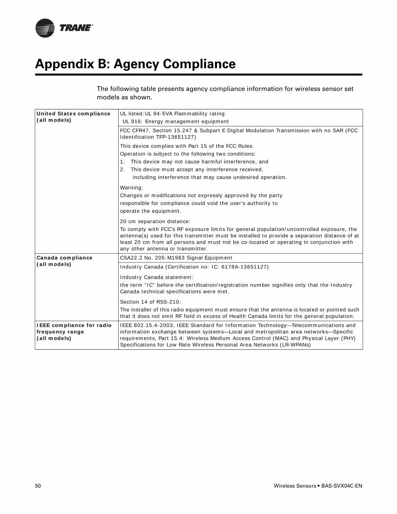
Appendix B: Agency Compliance
The following table presents agency compliance information for wireless sensor set models as shown.
United States compliance(all models)
UL listed:UL 94-5VA Flammability ratingUL 916: Energy management equipment
FCC CFR47, Section 15.247 & Subpart E Digital Modulation Transmission with no SAR (FCC Identification TFP-13651127)
This device complies with Part 15 of the FCC Rules. Operation is subject to the following two conditions: 1. This device may not cause harmful interference, and 2. This device must accept any interference received, including interference that may cause undesired operation.
Warning:Changes or modifications not expressly approved by the party responsible for compliance could void the user’s authority to operate the equipment.
20 cm separation distance:To comply with FCC’s RF exposure limits for general population/uncontrolled exposure, the antenna(s) used for this transmitter must be installed to provide a separation distance of at least 20 cm from all persons and must not be co-located or operating in conjunction with any other antenna or transmitter.
Canada compliance(all models)
CSA22.2 No. 205-M1983 Signal Equipment
Industry Canada (Certification no: IC: 6178A-13651127)
Industry Canada statement:the term “IC” before the certification/registration number signifies only that the Industry Canada technical specifications were met.
Section 14 of RSS-210:The installer of this radio equipment must ensure that the antenna is located or pointed such that it does not emit RF field in excess of Health Canada limits for the general population.
IEEE compliance for radio frequency range(all models)
IEEE 802.15.4-2003, IEEE Standard for Information Technology—Telecommunications and information exchange between systems—Local and metropolitan area networks—Specific requirements, Part 15.4: Wireless Medium Access Control (MAC) and Physical Layer (PHY) Specifications for Low Rate Wireless Personal Area Networks (LR-WPANs)


Literature Order Number BAS-SVX04C-EN
Date April 2008
Supersedes New
Trane has a policy of continuous product and product data improvement and reserves the right to change design and specifications without notice.
www.trane.com
For more information, contact your local Trane office or e-mail us at [email protected]