Varispeed-501)W11 · Varispeed-501)W11 INDUSTRIAL USE ... Store the equipment under the following...
20
Varispeed-50 1)W11 INDUSTRIAL USE THYRISTOR CONVERTER UNITS Before initial operation, read these instructions thoroughly, and retain for future reference .
Transcript of Varispeed-501)W11 · Varispeed-501)W11 INDUSTRIAL USE ... Store the equipment under the following...

Varispeed-501)W11INDUSTRIAL USE THYRISTOR CONVERTER UNITS
Before initial operation, read these instructions thoroughly, and retain for future reference.

When properly installed, operated and maintained, thisunit will provide a lifetime of optimum operation. It ismandatory that the person who operates, inspects, andmaintains this equipment thoroughly reads andunderstands this manual and has in his possession atall time .
IMPORTANT
. Make no withstand voltage test on the VS-505WIIbecause it incorporates semi-conductor electroniccircuits .
. If insulation resistance tests are neccessary, makethem only in accordance with the instructions given inthis manual.
682-215
Type CDMR-W11
Type CDMR-WIL(Type S)
(Type L)460 V, 105 A
460 V, 420 A
CONTENTS
682-234
. Do not tamper with potentiometers of the power unitssince they were preset at the factory before shipment.
Varispeed-505W11 (VS-505WII) is a thyristor converterunit for varispeed reversible operation of industrial DCmotors .
For correct operation of VS-505WII, users mustthoroughly read these instructions . This manual is alsonecessary for maintenance and troubleshooting, andthrefore should be kept filed for ready reference.
For details on DC motors, refer to "Instructions forIndustrial DC Motors" (TOE-C435-3B).
Type CDMR-W11(Type M)
230 V, 260 A
682-227
RECEIVING . . . . . . . . . . . . 3 Interconnections . . . . . . . . . . . 4 MAINTENANCE . . . . . . . . 10
STORAGE . . . . . . . . . . . . . . 3 Cautions when Wiring . . . . . . 4 Periodic Inspection . . . . . . . 10
LOCATION . . . . . . . . . . . . . 3 TEST RUN . . . . . . . . . . . . . . 5 Parts Replacement . . . . . . . 10INSTALLATION . . . . . . . . . 3 Check before Test Cautions in ReplacingWIRING . . . . . . . . . . . . . . . . 3 Run . . . . . . . . . . . . . . . . . . . . 5 Control Board . . . . . . . . . . . 14
Component Arrangement No-Load Operation . . . . . . . . 6 Troubleshooting Guide . . . . 14in VS-505WH . . . . . . . . . . . . 3
Full-Load Operation . . . . - 6 SPAREPARTS . . . . . . . . . . 15Terminal Sizes andCarrying Currents . . . . . . . . . 4 Adjustment . . . . . . . . . . . . . . 6 REFERENCE. . . . . . . . . . . . 16
RECEIVING
or missing .
STORAGEIf the equipment is temporarily stored or ma-chine stops for an extended length of time, thefollowing precautions should be taken .
LOCATION
Store the equipment under the following condi-tions." Free from rainfall and drops of water" Clean and dry
(a) Control Circuit
" Free from corrosive gas and liquid" Ambient temperature : OOC to 400 C
WIRII4GMake wiring in reference to the interconnectiondiagram furnished on your order and the follow-ing .
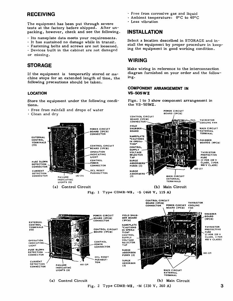
COMPONENT ARRANGEMENT INVS-505WII
Figs . 1 to 3 show component arrangement inthe VS-505WII .
NAMEPLATE"CAUTIONSI N OPERA-TION"CONTROLSUPPLYVOLTAGESELECTORTAP
POWER CIRCUITBOARD (2PCB)
(a) Control CircuitFig. 1 Type CDMR-WI[, -S, (460 V, 115 A)
(b) Main Circuit
CONTROL CIRCUITBOARD (1PCB)
THYRISTORCONNECTOR
POWER CIRCUIT COOLINGBOARD (2PCB)
FAN
MAIN CIRCUITEXTERNALTERMINAL
(b) Main CircuitFig . 2 Type CDMR-WII, -1V[ (230 V, 260 A)
THYRISTORPROTECTIVEFUSE(2 FOR 220 VCLASS, 3 FOR440 V CLASS)
THYRISTORPROTECTIVEFUSE(2 FOR 220 VCLASS, 3 FOR440 V CLASS)
The equipment has been put through severetests at the factory before shipped . After un-packing, however, check and see the following .
" Less vibration
INSTALLATION" Its nameplate data meets your requirements ." It has sustained no damage while in transit . Select .a location described in STORAGE and in-" Fastening bolts and screws are not loosened . stall the equipment by proper procedure in keep-" Devices built in the cabinet are not damaged ing the equipment in good working condition .
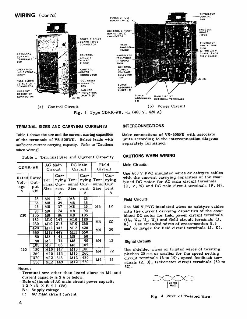
WIRING (Cont'd)
4
TERMINAL SIZES AND CARRYING CURRENTS
Table 1 shows the size and the current earring capacitiesof the terminals of VS-505WII . Select leads withsufficient current carrying capacity . Refer to "Cautionswhen Wiring".
Table 1 Terminal Size and Current Capacity
Notes- Terminal size other than listed above is M4 andcurrent capacity is 2 A or below.Rule of thumb of AC main circuit power capacity1.2XF XEXI (VA)E :
Supply voltageI :
AC main circuit current
SURGEABSORBERS
Control Circuit
(b) Power Circuit
Fig . 3 Type CDMR-WII:, -L (460 V, 420 A)
INTERCONNECTIONS
Make connections of VS-505WII with associateunits according to the interconnection diagramseparately furnished.
CAUTIONS WHEN WIRING
Main Circuits
Use 600 V PVC insulated wires or cabtyre cableswith the current carrying capacities of the com-bined DC motor for AC main circuit terminals(U, V, W) and DC main circuit terminals (P, N) .
Field Circuits
Signal Circuits
MAIN CIRCUITEXTERNAL TERMINALS
Use 600 V PVC insulated wires or cabtyre cableswith the current carrying capacities of the com-bined DC motor for field power circuit terminals(Uo, Wo, U1 , Wl) and field circuit terminals (J,K) .
Use stranded wires of cross-section 5.5mm2 or larger for field circuit terminals (J, K) .
Use shielded wires or twisted wires of twistingpitches 20 mm or smaller for the speed settingcircuit terminals (6 to 10) , speed feedback ter-minals (2, 3), tachometer circuit terminals (50 to52) .
Fig . 4 Pitch of Twisted Wire
AC Main DC Main FieldCDMR-W11 Circuit Circuit Circuit
Car- Car- Car-Rated Rated
Ter- rying Ter- rying Ter- ryingVolt- Out- minal Cur- minal Cur- minal Cur-agee put rent Size rent Size rentV kW A A A
25 M4 21 M5 2535 M8 29 M8 3545 M8 37 M8 45 M4 1290 M8 74 M8 90
230 105 M8 86 M8 105180 M10 147 M10 180 M4 22260 M10 213 M10 260420 M12 343 M12 420
M4 25550 -M12 449 M12 .55050 M8 41 M8 5090 M8 74 M8 90 M4 12105 M8 8 'M8 105
460 180 M10 147 M10 180 M4 22260 M10 213 M10 2&0420 M12 343 M12 420 M4 25550 M12 449 M12 550
Separation of Signal Cables from MainCircuit Cables
To avoid inductive interference from other cables,run the shielded or twisted wires (1 to 55)separate from main circuit cables (U , V, W ; U o , WO ;U1, W1 ; P, N ; J, K) in a bundle or thru a duct .
CAUTION
After wiring, check interconnections . Make in-sulation resistance tests using a 500 V megger .Connect VS-505WIE main circuit terminals (U, V,W;
Uo, Wo ;
U1, W1; P, N ; J, K) with commonlead . Measure the insulation resistance betweencommon lead and the ground . When the testresult is 2 MSZ or more, it means that wiring isgood.
TEST RUNWhen the VS-505WIL has been correctly installedand wired, the unit shall be tested through atest run as follows .
If trouble is found during the test run, re-fer to "Check Before Test Run" and "Trouble-shooting Guide" for necessary measures . If thecause of the trouble cannot be located, or repairis impossible, notify our service station, givingthe details of trouble conditions .
CHECK BEFORE TEST RUN
Make the following checks prior to the test run .
Table 2 Check before Test Run
* VS-505WE of larger capacity than 230 V, 45 A or 460 V , 90A are provided with a thyristor cooling fan.
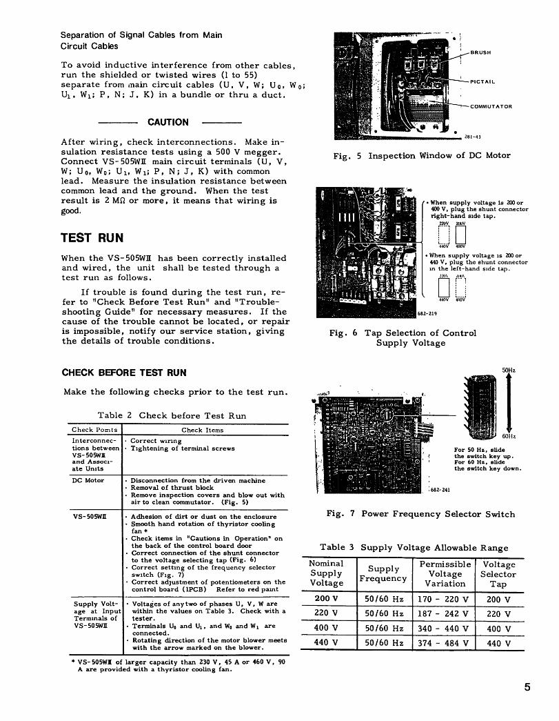
Fig . 5 Inspection Window of DC Motor
DFig . 6 Tap Selection of Control
Supply Voltage
Table 3 Supply Voltage Allowable Range
50Hz
60Hz
For 50 Hz, slidethe switch key up .For 60 Hz, slidethe switch key down .
Fig . 7 Power Frequency Selector Switch
Check Pomts Check Items
Interconnec- " Correct wiringtions between " Tightening of terminal screwsvs- 505WEand Associ-ate Units
DC Motor " Disconnection from the driven machine" Removal of thrust block" Remove inspection covers and blow out withair to clean commutator . (Fig . 5)
VS-505WII " Adhesion of dirt or dust on the enclosure" Smooth hand rotation of thyristor coolingfan
" Check items in "Cautions in Operation" onthe back of the control board door
" Correct connection of the shunt connectorto the voltage selecting tap (Fig . 6)
" Correct setting of the frequency selectorswitch (Fig . 7)
" Correct adjustment of potentiometers on thecontrol board (1PCB) Refer to red paint
Supply Volt- " Voltages of any two of phases U, V, W areage at Input within the values on Table 3. Check with aTerminals of tester .VS-505WR " Terminals Uo and U1 , and Wo and W, are
connected ." Rotating direction of the motor blower meetswith the arrow marked on the blower .
NominalSupply Permissible Voltage
SupplyFrequency Voltage Selector
Voltage Variation Tap
200 V 50/60 Hz 170 - 220 V 200 V220 V 50/60 Hz 187 - 242 V 220 V
400 V 50/60 Hz 340 - 440 V 400 V440 V 50/60 Hz 374 - 484 V 440 V

TEST RUN
(Cont'd )NO-LOAD OPERATION
After making the checks specified before test run,thoroughly check the environment of the system forsafety.
Check the polarity of DC tachometer generatorfeedback voltage. When the motor is running forward,the polarity of VS-505WIl signal terminal 2 (3 :
0 V) isminus and it is plus during reverse running of the motor.
Then, run the motor without load according toTable 4.
FULL-LOAD OPERATIONBefore starting full-load operation, stop the powersupply, couple the DC motor to the driven machine, andcheck the motor and the driven machine for safe andobstruction-free conditions . Table 5 gives full-loadoperation procedure.
Table 4 No-load Operation
* VS-505W11. rated 220V. 45 A and above and 460V. 90 A and above areprovided with a thyrlstor cooling fan.
6
ADJUSTMENT
Do not tamper unnecessarily with the potentiometers onthe control circuit board since they have been adjustedat the factory before shipped.
Adjuster Locations and Functions
Adjuster locations on the control circuit board andfunctions are shown in rig. 8 and Table 6. Thecharacteristics of control circuit board check terminalsare shown in :Fig. 9 andTable 7.
0
sx V~0
Fig . 8 Adjuster Locations onControl Circuit Board
'fable 5 Full-load Operation
Order Operation Check Items91 Set the speed referenceat zero .
2 Turn on main circuit Smooth rotation of thepower suppy . thyristor cooling fan .
Smooth rotation of theblower for DC motor.Rotating direction of theblower meets with the mark-ing on the blower .
3 Make an operational se- Indication light "PREP" onquence and check to be the control board (1PCB)sure that operation is turns on .ready. (Turn on readysignal, motor cooling fanON /OFF signal .)
4 Turn-on the operationsignal .
5 Gradually, increase the Smooth acceleration of DCspeed setting value. motor.
No abnormal odor, smoke,vibration and noise on DCmotor.
6 Remove the hand-hole No brush chattering andcover and check the
Isparking at the brushes .
commutator .
To avoid excessive temperature rise of DC motorwinding in frame 112, 132, reclose the windowwithin 5 minutes .
7 Gradually, turn the Smooth acceleration of DCspeed setting potentiom- motor.eter clockwise.
8 ' Increase the speed set- DC motor rotates at theting value to the maxi- maximum speed . Checkmum . with a speedometer.
9 Change the speed to DC motor speed corre-various values . sponds with the set values .
10 Turn off the operation DC motor suddenly stops .signal .
11 Turn off the main cir-cult power supply .
Order Operation
1 Set the speed at zero .
2 Turn on the main circuit power supply .
3 Turn on operation signal and graduallyincrease the speed. Check to be surethat the motor and driven machine arecorrectly running .
4 Turn off the operation signal .5 Turn off main circuit power supply .

Table 6 Control Circuit Board Adjuster Locations and FunctionsType : o Adjuster Adjuster Adjuster Function Adjusting Method SpecificationsAdjusters Location Name
1 ~+ RATE Accel time adjustment at fwd run. Clockwise rotation increases 3 - 75 sec(Decel time adjustment at rvs run.) accel time .
2 (D RATE Decel time adjustment at fwd run Clockwise rotation increases decel time . 3 - 75 sec(Accel time adjustment at rvs run.)
3 NGAIN ASR Gain adjustment . Clockwise rotation increases GAIN
4 Speed feedback adjustment . Clockwise rotation decreases ±6 V/10046 specANMAX s"geed .
5 IGAIN ACR Gain adjustment . Clockwise rotation increasesgain .
6Main circuit current feedback Clockwise rotation decreases +3 V/100% current
IFB adjustment . current.
7 F LIMIT Speed and current limit value at Clockwise rotation increases 150% (Standard)forward run. limit value .
8 R LIMIT Speed and current limit value at Clockwise rotation increases 150% (Standard)reverse run. li mit value .
9 CEMF Counter electromotive force Clockwise rotation increases 0. 17 - 0.84 timesPotenti- compensation . gain .ometers 10 SM
Speedometer adjustment . Clockwise rotation increases 1 mADC max.pointer swin : .
Ammeter adjustment. Clockwise rotation increases pointer 1 mADC max11 AM swing.12 NOFS ASR offset adjustment .
evolt.i z- e13 IOFS ACR offset adjustment. t-volta,", .-e
14 KIPP Phase shift lag limit adjust- Clockwise rotation advances shift lag 155oek Standardment limitAdjustment of phase shifter Clockwise rotation advances 90'-k - li_T1i°eZ
15 PSBoperation point . :, hase . (Adjustable)Setting overload detection Clockwise rotation increases 110% Standard
16 OL% start point. overload detection start.,oint.
17 OLTSetting overload detection Clockwise rotation increases 150%, 6.0 sec (Standard)time. o .eration time .
18 ZCD Setting zero current detec- Clockwise rotation increases 0% - 10n (Adjustable)tion level. detection level. 7% (Standard)
19 IREF Setting field current. Clockwise rotation increasesfield current .
Resistor 2014FBR1FBR - Rough adjustment of field cur-
Selection rent detection voltage level . Open the resistor according Refer to motor specifi-(Open) 21 5FBR - Rough adjustment of main circuit to specifications . cations .
9FBR current detection voltage level .
Slide 22 1SW Control Method selector (Speed N-1 Current
Switch control) control)~M®50 Hz- " 0 Hz
Rough adjustment of speed Selection o the voltagelevel24 A - D detection voltage level. according to type of tack-gen
and motor rated s . , eed .25 E Selection of soft start El
operation E2 Soft startSelection of PI or P control by © PI control
26 FACR control method "A P controlSelection of PI or P control by © Pcmntrol
Plug27 H ASR control method © P1 controlcontrol
Selection Selection of zero-speed condi- J 1 block after motor28 tion at motor overheat . reached zero speed byJ
stop o .eration .~~ ime(giate gate block .
29 K Selection of start interlock ©Witzero-speed condition . ~~ WithoutSelection of zero-speed cord- Field half-reduced aftertion at motor blower stop . ttiotor zero-speed by stop
30 L _operation. (Gate block)
Field half-reduced immediately.-
(Gate block)Selection of exciter according I©Exciter used .
31 M to type of motor field. © Exciter notused .Open " Speed control by
voltage detection." Speed control by AC
Short- 32 OPN tach-gen .circuit Short-Jumper circuited other than the above.
Open- Special application .33 OPS -- Short- Other than the above .
circuited

TEST RUN (Cont'd)
Adjustment Procedure
Fig . 9 Control Circuit Check Terminals
NMAX (Speed feedback adjustment)
Table 7 Control Board Check Terminals
To adjust the DC motor speed exactly to thereference speed, proceed as follows .
1 . Prepare the tachometer having the requiredaccuracy .
2 . Operate the DC motor at no load (or lessvariation) .
3 . Measure the speed reference voltage with avoltmeter . Correct the voltage to that of desiredmotor speed .4 . Measure the motor speed with a tachometer .
5 . If the speed does not reach the desired speed,turn NMAX counterclockwise to increase thespeed.
Signal NameCheck
TerminalsNormal Value
CH22 OV (SG)
Stable power supply CH24 +15 V
CH25 -15 V
CH19 +24 V
CH20 -24 V Allowable voltageUnstable power supply
CH23 +24 V (Pulse amplifiersupply)
function range : ±20%
CH4 :6 V/100% command (8 Forward, (+ Reverse)Speed reference CH5 ±6 V/100% command ((D Forward, (DReverse)
Speed feedback CH3 ;6 V /100% speed (0 Forward,+ Reverse)
Forward CH9Current command Reverse CH8 -3 V/100% command
Current limit Forward CH7 +3 V/100% current limit(Speed limit) Reverse CH6 (+6 V/100% speed limit)
Main Current feedback CH18 +3 VI100% currentCircuitPower Current limiter output CH2
. -1 V at gateockblApprox 0 to +6 V when controlling
Phase shifter input CH16Approx . +5.5 V at 60 Hz,+6.5 V at 50 Hz at gateblock.
+1 to +5.5 V at 60 Hz,+1 to +6.5 V at 50 Hzwhen controlling .
Counter electromotive force input CH1 0 - ±5 V
Overload detection start point CH21 110% (Approx: -1.65 V)
Zero-current detection CH15 0 V at load current conduction, approx . +12 V at0 A of load current.
Pulse amplifier power Forward C1112 0 V at reverse opera-tion .
Approx . +24 V at forwardoperation.
supplyReverse CH13 0 V at fozwaz~d opera-
tion .Approx . +24 V at reverseoperation.
Gate block (at failure) CH14 0 V normal, :!pprox . -12 V at gate block.
u Uu
Phase shifter synchronization v 4/_~s ar U, V, W: Main circuitpower supply w w 11 y input power supply .
Current command CH11 Voltage according to ~ -6 V/5 A
Field Current feedback CH17 field current. +3 V/5 A
PowerPhase shifter input CH10
Approx . +5 V at 60 Hz,+6 V at 50 Hz at fieldblock.
+1 to +5 V at 60 Hz,+1 to +6 V at 50 Hzwhen controlling.
6. If the speed exceeds the desired speed, turnNMAX clockwise to decrease the speed .
FLIMIT (Forward limit value adjustment)RLIMIT (Reverse limit value adjustment)
1 . Current limitation (Speed control)
Slide the control method selector switch (1SW) onthe control circuit board to N . When the voltagesat CH7 (forward) and CH6 (reverse) are +3 V,100% current limit value is obtained . Current limitvalue can be set within the range of 0% to 250% byF LIMIT and R LIMIT .
2 . Speed limitation (Current control)
Slide the control method selector switch (1SW) onthe control circuit board to I . When the voltagesat CH 7 (forward) and CH 6 (reverse) are +6 V,100% speed limit value is obtained . Speed limitvalue can be set within the range of 0% to 250%by F LIMIT and R LIMIT .
PSB (Phase shifter operating point adjustment)
PSB sets the phase shifter operating point .
1 . When the current controller (ACR) is inte-gral-controlledConnect the plug selector F on the control circuitboard at Fl . Turn PSB fully counterclockwise .
2 . When the current controller (ACR) is ratio-controlledConnect the plug selector F on the control circuitboard at F2 . Turn PSB clockwise gradually withreference current at 0 V (0 V at CH 2) , and setat the position where main circuit current isready to start .
CEMF (Counter electromotive force compensation)
Current loop is vulnerable to counter electro-motive force . In order to obtain optimum per-formance, a compensating electromotive force hasto be biased on the phase shifter, depending onthe control mode .
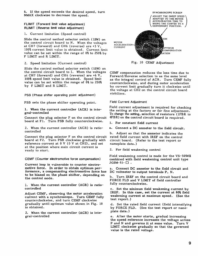
1 . When the current controller (ACR) is ratio-controlledAdjust CEMF, observing the motor accelerationcurrent with a synchroscope . Turn CEMF fullycounterclockwise, and turn CEMF clockwisegradually until optimum value shown in Fig . 10is obtained .
2 . When the current controller (ACR) is inte-gral-controlled
MOTORACCELERATIONCUR1tENT
Field Current Adjustment
Fig . 10 CEMF Adjustment
CEMF compensation reduces the loss time due toForward/Reverse selection to as the same levelas the integral control of ACR . Turn CEMF fullycounterclockwise, and during motor accelerationby current limit gradually turn it clockwise untilthe voltage at CH2 on the control circuit boardstabilizes .
Field current adjustment is required for checkingthe setting at the factory or for fine adjustment .To change the setting, selection of resistors (1FBR to4FB R) on the control circuit board is required .1 . For constant field currenta. Connect a DC ammeter to the field circuit .b . Adjust so that the ammeter indicates therated field current with IREF on the controlcircuit board . (Refer to the test report ornameplate data .)
2 . For field weakening control
SYNCHROSCOPESCREENADJUST THE SWEEP SPEEDADAPTED TO THE MOTORACCELERAITON TIME TOBRING THE CURVES TO ACONVENIENT POSITION .
Field weakening control is made for the VS-505WIIcombined with field weakening control unit typeJGSM-51- D .
a . Connect DC ammeter to the field circuit andDC voltmeter to output terminals P, N .b . Turn IREF on the control circuit board andFORCE FLD and V LIMIT of field controllerfully counterclockwise .c . Seat the minimum field weakening current byIREF. In this case, set the current at 80% fieldweakening current at maximum speed . (See thetest report .)d . Set the rated field current (field intensifyingby FORCE FLD .
(See the test report or name-plate data .)e . Alter the motor starts, gradual increasingthe speed reference increases the voltage acrossP and N and governs it at some value .
Turn VLIMIT clockwise gradually so that the governedvalue is the rated voltage .
MAINTENANCEVS-505WIl requires almost no daily inspection .To keep the correct and successful operation,periodic maintenance operations should be per-formed . The users should prepare their ownmaintenance programs based on the followingguidelines .
PERIODIC INSPECTION
Table 8 shows the minimum inspection items andthe procedures .
Table 8 Periodic Inspection
PARTS REPLACEMENT
. Replace the parts required after checking thetrouble and correcting it according to TROUBLE-SHOOTING GUIDE .
. Turn off the power before part removal ormounting .
10
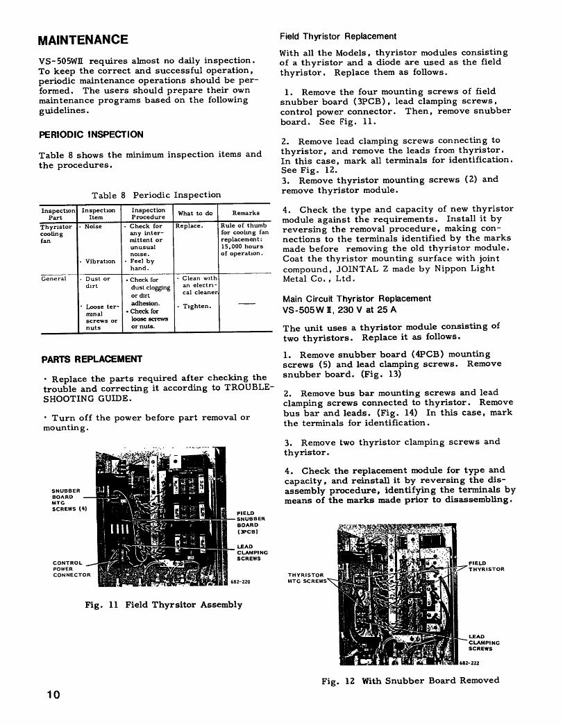
Fig . 11 Field Thyrsitor Assembly
Field Thyristor Replacement
With all the Models, thyristor modules consistingof a thyristor and a diode are used as the fieldthyristor . Replace them as follows .
1 . Remove the four mounting screws of fieldsnubber board (3PCB), lead clamping screws,control power connector. Then, remove snubberboard . See Fig . 11 .
2 . Remove lead clamping screws connecting tothyristor, and remove the leads from thyristor.In this case, mark all terminals for identification .See Fig . 12 .3 . Remove thyristor mounting screws (2) andremove thyristor module .
4 . Check tY;Ie type and capacity of new thyristormodule against the requirements . Install it byreversing the removal procedure, making con-nections to the terminals identified by the marksmade before removing the old thyristor module .Coat the thyristor mounting surface with jointcompound, JOINTAL Z made by Nippon LightMetal Co. , Ltd .
Main Circuit Thyristor ReplacementVS-505W 1, 230 V at 25 A
The unit uses a thyristor module consisting oftwo thyristors . Replace it as follows .
1 . Remove snubber board (4PCB) mountingscrews (5) and lead clamping screws . Removesnubber board. (Fig . 13)
2 . Remove bus bar mounting screws and leadclamping screws connected to thyristor . Removebus bar and leads . (Fig . 14) In this case, markthe terminals for identification .
3 . Remove two thyristor clamping screws andthyristor.
4 . Check the replacement module for type andcapacity, and reinstall it by reversing the dis-assembly procedure, identifying the terminals bymeans of the marks made prior to disassembling .
THYRISTORMTG SCREWS
Fig . 12 With Snubber Board Removed
InspectionPart
InspectionItem
InspectionProcedure What to do Remarks
Thyristor " Noise " Check for Replace . Rule of thumbcooling any inter- for cooling fanfan mittent or replacement :
unusual 15,000 hoursnoise . of operation .
" Vibration " Feel byhand . -
General " Dust or . Check for Clean withdirt dust clogging an electri-
or dirt cal cleaner
" Loose ter- adhesion. , Tighten .minal " Check forscrews or loose screwsnuts or nuts .

Main Circuit Thyristor Replacement
VS-505W 1, 230 V at 35 to 105 A, 460 V at 50 to105 A
The unit uses a thyristor module consisting oftwo thyristors . Replace it as follows .
1 . Remove snubber board (4PCB) mountingscrews (5) and remove snubber board. (Fig . 15)
2 . Remove bus bar mounting screws and leadclamping screws connected to thyristor . Removebus bar and leads . (Fig . 16) . In this case, markthe terminals for identification .
3. Remove two thyristor clamping screws andthyristor .
4 . Check the replacement module for type andcapacity, and reinstall it by reversing the dis-assembly procedure, identifying the terminals bymeans of the marks made prior to disassembling .Coat the thyristor mounting surface with jointcompound, JOINTAL Z made by Nippon LightMetal Co . , Ltd .
SNUBBERBOARD.TGSCREWS (5)
Fig . 13 Field Thyristor Assembly (230 V, 25 A)
Fig. 14 With Snubber Board Removed
Main Circuit Thyristor Replacement
VS-505W 1, 230 V at 180 to 550 A, 460 V at 180 to550 A
The VS-505WIE uses a flat thyristor module as apower module .
For 180 A and 260 A, one powermodule is employed, and for 420 A, and 550 A,three power modules are employed . Proceed asfollows .
1 . Remove the clamping screws for thyristorgate (C) and cathode (K) terminals (24 for 260 Aor below, and 8 for 420 A or more), and free theleads . Remove fuse mounting bolt(s) (3 for 260A or below and 1 for 420 A or more) .
(Fig . 17)
2. Loosen power module mounting bolts (7 for260 A or below, 8 for 420 A or more) , and removethe power module .
THYRISTORCLAMPING -SCREWS
S14UBBERBOARDMTGSCREWS (5)
Fig . 15 Main Circuit Thyristor Assembly(460 V, 105 A)
BUSBAR-
Fig . 16 With Snubber Board Removed

MAINTENANCE (Cont'd )
3 . Place the main circuit thyristor module on awork bench . Remove the snubber board (4PCB-U, V, W) mounting screws (3 for 260 A or below,4 for 420 A or more), and take out the snubberboard . (Fig . 18)
4 . Loosen the fin mounting nuts alternately,turning 1/4 turn at a time . Then, remove theleaf spring .
5 . Remove the fin and take out the leaf spring .
6 . Clean the contact surfaces of the new thy-ristor and the fin, and thinly coat these surfaceswith joint compound, JOINTAL Z made by NipponLight Metal Co ., Ltd .
7. Align the fin locating pin and the thyristorlocating hole, after making sure that the polarityof the thyristor is correct.
8 . Keeping the leaf spring and the fin in paral-lel, finger-tighten the clamping nuts . Then,tighten them alternately through 1/4 turn at atime, three times each with a socket wrench .Now, the thyristor fin has been installed .
12
Thyristor Protective Fuse Replacement
2 . Remove the two fuse mounting bolts .
VS-505W 11, 230 V at 25 to 105 A, 460 V at 50 to105 A
1 . Pull up the fuse blown indicating microswitchwith the leads connected.
(Fig . 19)
3. Mount the replacement fuse by reversing theremoving procedure, after checking it for modeland capacity .
9 . Tighten the snubber board mounting screws .Then, mount the thyristor module by reversingthe disassembling procedure, tightening thescrews firmly .
THYRISTORGATE (G)CATHODE (K)TERMINALS
FUSE
K (RED)
G (WHITE)
THYRISTOR
681-193
(a) With Thyristor Removed
Fig . 18 Thyristor Replacement
(b) Thyristor
Fig. 17 Main Circuit Thyristor(460 V, 420 A)
Fig . 19 Main Circuit Fuse Assembly(460 V, 105 A)

Thyristor Protective Fuse Replacement
VS -505W 1, 230 V at 180 to 550 A, 460 V at 180to 550 A
1 . Remove the two lead clamping screws of thefuse-blown indicating mocroswitch and freethe leads . (Fig . 20)
2 . Remove the two fuse mounting bolts, andremove the fuse together with the fuse-blownindicating microswitch .
3 . Check the replacement fuse for model andcapacity, and install it by reversing the disas-sembling procedure .
Surge Absorber Fuse Replacement
Surge Absorber Replacement
Fig . 20 Main Circuit Fuse Assembly(460 V, 420 A)
1 . Pull the fuse element and remove it . (Fig . 21)
2 . Mount the replacement fuse, after checkingits model and capacity .
Fig . 21 Surge Absorber Fuse
1 . Remove three surge absorber mountingscrews and remove surge absorber .
2 . Check the replacement surge absorber formodel and capacity . Mount three surge ab-sorbers after connecting M4 pressure termi-nals to their leads as shown in Fig . 22 .
IL)k,
Thyristor Cooling Fan Replacement
Fig . 22 SurgeAbsorber with Pres-sure TerminalsConnected to Leads
To replace a thyristor cooling fan with a new one,proceed as follows .
(Fig . 23) The VS-505WILunits
rated 230 V, 25 A ; 460 V, 50 A are self-cooled type .
1 .
Remove the cooling fan power lead .
2 . Unscrew the two fan mounting screws anddismount the fan .
3 . Remove the fan by reversing the disassembl-ing procedure.
(a) 230 V, 45 to 105 A; 460 V, 90/105 A
FAN
POWER SUPPLYLEADS (2)r . .
(b)
230 V, 180/260 A; 460 V, 180/260 A
(c)
230 V, 420/550 A ; 460 V, 420/550 AFig. 23 Thyristor Cooling Fan
13

MAINTENANCE (Cont'd )
Control Circuit Board Replacement
Disconnect all the leads from the terminals.Then, unplug the connectors shown in Fig. 24, and remove the6 control circuit board mounting screws .
Mount the new board by reversing the disassemblingprocedure. Plug-in the connectors firmly.
CAUTIONS IN REPLACING CONTROL CIRCUIT BOARD
TROUBLESHOOTING GUIDE
1 4
EXTERNALCONTROLTERMINALS
FUSE-BLOWNDETECTIONCONNECTOR
CURRENTDETECTIONCONNECTOR
Make sure that the type of the new control circuit board agreeswith the nameplate and potentiometer settings of new controlcircuit board are the same as the old one. Refer to thenameplate "Cautions in Operation" posted on the inside of thecontrol circuit board door of VS-505WII. See Table 6 "AdjusterLocations on the Control Circuit Board and Functions" .
Fig. 24 Control Board
Table 9 Troubleshooting Guide
Note : If the reading is not m . accurate measurement with a 500 V megger is required .
Reading must be 3 megohms or above .
Trouble Possible cause Check method What to doPREP lamp Control Failure indicatingOFF printed lamp ON .
board Operation sequence Check the external operation sequence ._
Replace the control board . SeeReplace-failure . ment of Control Board .
OCL lamp Control Too low setting of Is setting dial at the positions indicated Set the setting dial to theON printed "OL%," "OLT" . b lock " dint? position of lock dint .
board Too high setting of"FLIMIT," "RLIMIT" Refer to Tables 6and 7.Incorrect setting of Readjust .
"IFB':Thyristor Defective deterto- Check thyristor (Fig . 25) . Replace thyrtstor . (See Main
rated). Circuit Th rtstor on page 9 . )Motor and Overloaded . Check load current . A iust loa . Reset .driven Locking . Run motor without load, and see if it locks Repair motor .machine Check load for locking .
Layer shorting in Run motor with terminals P and N dis- Repair motor .motor . connected . If OCL lamp does not light,
the motor and its circuit are defective .Grounding of motor Measure resistance between terminal P) " Repair motor .circuit . (or N) and ground (E) with a multitester . " Correct wiring .
If the reading is nearly - on the largestscale of the tester, the circuit is normal .
U lamp Thyristor Defective deterto- Check thyrtstor (Fig . 25) Replace thyrtstor . (See Main CircuitON rated). Th rtstor on page 9 .
Motor Layer shorting in Operate only board with (P) and (NT-1-s- Repair motor .motor. connected . If fuse is not blown, motor
circuit is defective .Grounding of motor Measure resistance across terminal I' or " repair motor . To replacecircuit . N) and ground (E) with a multitester, and " Correct wiring . fuses (1FU,
if the reading is nearly m on the largest ZFU . 5FU),scale of the tester, the circuit is normal . refer to
o (See Note .) Replacementt;
Control Defective phase Ifthemotor isnormal . replace of Thyristorcircuit control circuit) . control circsut board . Refer Protection
"O board to Replacement of Control Fuse .
c Circuit Board on page 13 .c Fuse Defective deterio-
rated). _FL lamp Motor Layer shorting in Measure resistance across terminal J and " Repair motor .ON field winding . K with converter terminal J and K dis- " Replace fuse . (3FU or 4FU) .
connected with a tester . If it indicatesm, it means- field circuit is disconnected .
Grounding of field Measure resistance across terminal (.I or Kcircuit . and ground (E) with a multitester, and if
the reading is nearly m on the largestscale of the tester, the circuit is normal .
Control Defective. If the motor is normal, replace control
[boardcircuit board . See Replacement of Control
Board on pa _ e 13 .THG lamp Motor Over Main circuit Check load current . ' Ad ust load .ON loading . Field circuit Check field current . Head ust . See Adjustment on page 7 .
Locking . Run motor without load, and see if it locks . Re it motor .Check load for lockmf-.-, . A .' _'J .
Blocked air filter . Refer to the instructions for IndustrialDC Motors (TOE-C435-3) .
Insufficient cooling Check the blower for correct running Correct wiring .with blower . direction .
MCF lamp Motor Cooling blower stop . Check fan for locking or overloadinE; . Repair or replace fan.ON _Check thermal relay for tri . .inTCF lamp Thyristor cooling an stop . Check fan for lockingoroverloading . Replace the thyristor cooling fan . SeeON Where the fan is provided with Replacement of Thyristor Cooling Fan,
failure sensor on page 12 .Surge Main CKT Excessive surge . Check fuses 3FU, 4FU . Eliminate cause of surge . Replace surgeabsorber and fuse . See Replacement of Surge offuse blown Absorber Fuse and Replacement of
Sure Absorber .

SPARE PARTS
Table 9 lists the recommended spare parts forone VS-505WII, keep always minimum insurancespare parts on hand to protect the unit againstcostly downtime. When ordering spare parts,
Table 10 Spare Parts for Control Panel
specify complete nameplate rating and descrip-tion (type, code no . , etc .) of the parts requir-ed, and quantity desired .
Thyristor Main circuit Thyristor Surge Absorber Fan Field Surge Control CircuitConverter Thyristor Protective fuse Fuse Thyristor Diode Absorber Board
CI)MlT WII Type (~' ty Type Q,ty Type I Q~ty Type Q
.ty Type
Q,tyType
Q.tY
T%peQ' t -̀(Code No ) (Code No ) (Code No ) (Code No .) (Code No) (Code No .) (Code No)
Type SS230 V TM20DA-II25 A (SCR195)
230 V 60FHS-5535 A TM25DZ-H (FU642)
230 V (SCR196)6 FCI"2-20
45 A (FU599)Type S
230 V TM55D7,-H 60FIIS-110 I 4715I'C-22T
90 A (SCR197) (FU644) -1330-1300
'(FAN130) '
230 V TM90D/.-1-1 60FIIS-150 I 2 .~ 1 TM20RA-Ii 2 'I'NR23G471 ' 3 JPDC_C041 I105 A (SC1?198) (FU615) (SCIZ192) (XX110) (FTCa1 ;2)
230 V N105CH08 CS5F-200 -~
M180 A (SCR259) (FU609)
I59151'C-22T
Type230 V CS5F-350
-1330-13tH)(FAN131)
,
260 A N195CH08 (FU612) FCF2-30230 V (SCR261) 12
CS5F-450 (FU600)
L
420 A (FU614) MlI.W18-Type
230 V 553PA80 CS5F-600 (FAN107)550 A (SCR263) (FU616)
460 V PK55IIB-160 -50 A (SCR244) 60FIiS-110460 V rI'M55DZ-21i (FU644 )90 A 1(SCR201) PCF2-20
Type S6
PK90HB-160 (FU599) HN4556MV460 V (SCII245) 60FHS-150 (FAN110) '105 A (TM90Dl,-211 (FU645)
\(SCH202)
'TM20IZA-l1 TNR23GIO2 'J1'DC-CO-113 1 2 3 1.160 V N105CI116 CS5F-200 (SCR192) (X X167) (ETCa172) ;
M180 A (SCR260) (FU609) 7556MXVType460 V CS5F-350 (FANI 11)2(i0 A N195CII16 12
(FU612) FCF2-30 j460 V (SCR262) CS5F-450 (FU600)
iL
420 A ( FU614 ) MRW18-Type
460 V 553PA160 CS5F-600 (fTAN107)550A (SCR264) (FU616) i
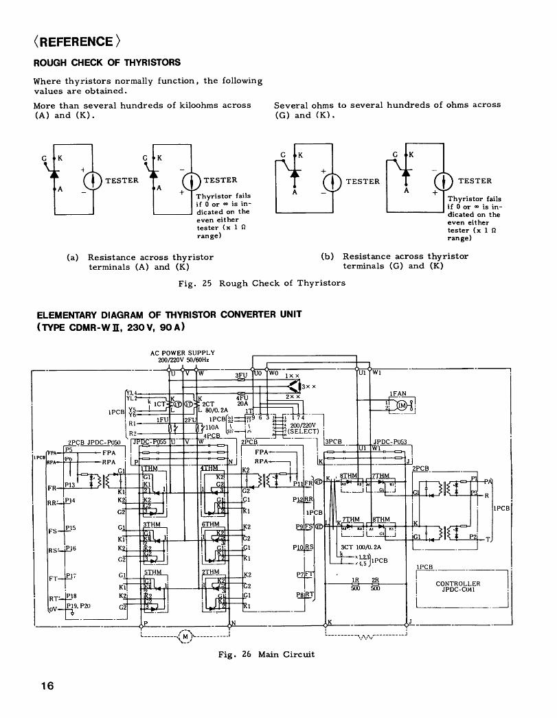
(REFERENCE)ROUGH CHECK OF THYRISTORS
Where thyristors normally function, the followingvalues are obtained .
More than several hundreds of kiloohms across
Several ohms to several hundreds of ohms across(A) and (K) .
(G) and (K) .
IPA
RPA
1 6
FS
FT
(a) Resistance across thyristor
(b) Resistance across thyristorterminals (A) and (K)
terminals (G) and (K)
ELEMENTARY DIAGRAM OF THYRISTOR CONVERTER UNIT(TYPE CDMR-W II, 230V, 90A)
P15
RT=4-p18P19, P20
1PCB
G1
K1K2G2
G1
K1
N3,4Y1,
Y5I R1Il R.)
JPDC-P05()FPA~ ,RPA i
G1
Thyristor failsi f 0 or - is in-dicated on theeven eithertester (x 1 0range)
Fig . 25 Rough Check of Thyristors
AC POWER SUPPLY200/220V 50/60Hz
----------- ~----------
Fig . 26 Main Circuit
500
W1
500
Thyristor failsif 0 or - is in-dicated on theeven eithertester (x 1 S2range )
CONTROLLERJPDC-CO41
R
1PCB

HALT ._27PREPARATION O
STOP 0 RUN 9
FLD ROCK
Flu (MCF)
FuH
TCFH
DC TG 20- 3+0
nv/ I(X)%
uw/ I(X)%
15v/ I(X)%SPFEOREFERENCE
FROM CONTROLTRANSFORMER
6
-P . 0V-+48VLOGIC CIRCUIT
+15V OV -15V(P)
23
CONTACT RATING220VAC 2A24 VDC 2ARUN
M-ONCOM
'
FLD CONTPREPARATION :
i{---------- _
L4 JGSM-51 9} T ~-6131415__l-i_
ipno
20, NAOULT
CUMNC
4 51 52 49 ©I2 3a s
©FBR
OCL
IREF
--24V
Fig . 27 Control Circuit
ESE
CHIT
CH17
ACR7,FK
50Hz4y60Hz,
NH 1
REVERSING CONTROLLER
ZC
0CH15
PS
llms llms
A
S
FBR
aoaa 10
SELECTOR SWITCH
n n n !ij4dj I IFLDIFB
CH12
CH131Q
v
TYPE :JPDC-CO41
Z~TF
FPA
RPA
RT
QRFI FROMPOWER PCBH
FROMPOWER PCBH

(REFERENCE) (Cont'd)
FUNCTIONS OF EXTERNAL CONTROL TERMINALS
1 8
Table 11 Functions of External Control Terminals for Input
Notes1. Use highly reliable contact for input interface signal considering that the load is 48 VDC, 10 mA .2. Provide a noise killer at both ends of coil when relays, contactors, etc. are used .
Signal Name Terminal Function1 Ready signal -
-°0-
30 "Close" --- Field intensifying ."O "men" --- Gate block + Field half-reduced .
2 Operation signal 29 "Close" --- Speed reference "ON" -; Acceleration to speed--0 reference value .
"Open" --- Speed reference "OFF" - Stop by regenerativebraking + Gate block.
29 "RUN" --- Speed reference "ON" -} Acceleration to spee,"reference value .
j j 28 "STOP" --- Speed reference "OFF" -" Stop by regenerative~ braking - Gate block.
3 Quickstop 27 Quick stop at ' Close' in case of soft start operation .signal -oo- "Close" --- Speed reference "OFF" -} Stop by regenerative
braking -r Gate block .4 Main circuit M 2 "Close" --- Gate block Terminals 26 and 35 (or 36)
input answer back ~0- released . short-circuited unless used .signal
5 Motor overheat 33 "Open" --- Gate block .si nal - - "Close" --- Normally .
" Field block signal 3 "Close" --- Fie143 block . (Field circuit clipped at PP-° °- phase .)
7 Motor blower 31 "Close" --- Field intensifying .ON /OFF signal °- "Open" --- Gate block -~ Field current half-reduced .
8 External gate _ 4 - 47 "Close" --- Gate block .block signal
9 External (OCL) 45 - 46 "Close" --- Normally. Terminals 45 and 4 " short-failure reset ~~- "Open" --- Reset . circuited when reset button in
the unit is used .10 Fuse blown R1 - R2 "Open" --- Normally .
detection signal "Close" --- Gate block .(inside)
11 Thyristor cooling R3 - R4 With failure detection cooling fan (option) .fan stop signal __0 "Open" --- Normally .(inside) "Close" --- Gate block �
12 Speed reference t& V/100$N " Soft start commnw" -"zei~~z : e.( 0+ Forward, (D 7 -4 V'100"" " 3 to 75 (Variable)Reverse) 8 ±10 V /100%N sec .
9 f157100%N Accel . time, decel. time ad-10 0 V (SG) justable independently .12 *6 V/ 100$N Terminals 11 an,. 1 short-
circuited.13 ±6 V/1000/6N
13 External currentreference ( (D 14 ±3 V/100% IaForward torque,0 Reverse 15 0 V (SG)torque)
14 Speed feedback - DCTG 2 3 (+)signal
15 CEMF compensation 48 Forward : 4 V/1U0% VaReverse: +6 V/100% Va
1 " Automatic field 1 Output received from field controller Type JGSM-51 .weakening currentcommand
17 Speed feedback 5 " Output from Type JGSM- 5(Voltage feedback) When reversible operation by ACTG . (OPN : Open)
" Output from type JGSM-53When speed controlled by voltage detection .(OPN : OP, en)
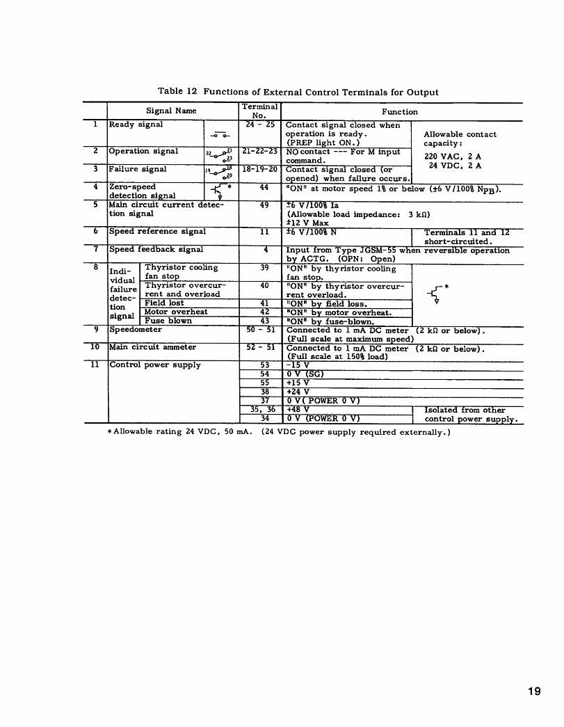
Table 12 Functions of External Control Terminals for Output
*Allowable rating 24 VDC, 50 mA.
(24 VDC power supply required externally .)
Signal Name TerminalFunction
1 Ready signal 24 - 25 Contact signal closed when..-0 operation is ready . Allowable contact
(PREP light ON .) capacity2 Operation signal zz 3 21-22-23 NO contact ---- For input 220 VAC, 2 Ao- command . 243 Failure signal 19~~ 18-19-20 Contact signal c ose " or VDC, 2 A
0-1-° opened) when failure occurs.4 Zero-speed 44 "ON" at motor speed 1% or below (±6 V/100% NPB) .
detection si nal5 Main circuit current detec- 49 - V 100 Ia
tion signal (Allowable load impedance : 3 k9Z)±12 V Max
6 Speed reference signal 11 -6 V/100% N Terminals 11 an(A 12short-circuited .
7 Speed feedback signal 4 Input from Type JGSM- when revers1p e operationb ACTG . (OPN : Open)
8 Indi- Thyristor cooling 39 "ON" by thyristor coolingvidual fan stop fan stop .failure Thyristor overcur- 40 "ON" by thyristor overcur-detec- rent and overload rent overload.tion Field lost 41 "ON" b field loss.signal Motor overheat 42 "ON"b motor overheat .
Fuse blown 43 "ON" b fuse-blown.9 Speedometer 50 - 1 Connected to 1 mA DC meter (2 kQ or below) .
(Full scale at_maximum speed)10 Main circuit ammeter - 1 Connected to 1 mA DC meter (2 kQ or below) .
(Full scale at 150% load)11 Control power supply 53 -15 V
54 0 V (SG)55 +15 V38 +24 V37 0 V( POWER0 V~~EP
+48 V Isolate(A from other34 V POWERTV control r,rpr~C-~ 1 ~1y .

Varispeed-505NA/IIINDUSTRIAL USE THYRISTOR CONVERTER UNITS
TOKYO OFFICE
Ohtemachi Bldg, 1-6-1 Ohtemachi, Chiyoda-ku, Tokyc, 100 JapanPhone (03) 3284-9111
Telex YASKAWA J33530
Fax (03) 3284-9034SEOUL OFFICE
Seoul Center Bldg, 91-1, So Kong-bong, Chang-ku, Seoul, KoreaPhone (02) 776-7844
Fax (02) 753-2639TAIPEI OFFICE
Shen Hsiang Tang Sung Chiang Building 10F 146 Sung Chiang Road, Taipei, TaiwanPhone (02) 563-0010, -7732
Fax (02) 567-4677YASKAWA ELECTRIC AMERICA, INC. - SUBSIDIARYChicago-Corporate Headquarters 2942 MacArthur Blvd Northbrook, Illinois 60062-2028, U SAPhone (708) 291-2340
Fax (708) 498-2430Chicago-Technical Center 3160 MacArthur Blvd Northbrook, Illinois 6()062-1917, U S APhone (708) 291-0411
Fax (708) 291-1028Los Angeles Office
5626 Corporate Avenue Cypress, CA 90630, U S APhone (714) 828-9692 Telex (230) 678396 YASKAWAUS TSTN Fax (714) 8'8-1165New Jersey Office
Riverdale One, 44 Route 23 North, Suite 5 Riverdal s, NJ 07457-1619Phone (201) 835-9512
Fax (201) 835-9511YASKAWA ELECTRIC EUROPE GmbH SUBSIDIARYNiederhochstadter Strafle 73,W 61476 Kronberg-Oberhochstadt. GermanyPhone (06173) 938-0
Telex 415660 YASE D
Fax (06173) 68421YASKAWA ELETRICO DO BRASIL COMERCIO LTDA . - SUBSIDIARYRua Conde Do Pinhal 8-5', Andar Sala 51 CEP 01501-Sao Paulo-SP, Br'EsilPhone (011) 35-1911
Fax (011) 37-7375YASKAWA ELECTRIC (SINGAPORE) PTE. LTD .CPF Bldg, 79 Robinson Road No 13-05, Singapore 0106Phone 2217530 Telex (87) 24890 YASKAWA RS
Fax (65) 224-5854
YASKAWA
YASKAWA ELECTRIC CORPORATION
TOE-S505-20C® Printed in Japan October 1993 63-4 0 5TA
682-215