
Variety of End Connections Flow coefficients (Cv) include ...
8
C 2017 HY-LOK CORPORATION All rights reserved Integral Bonnet Needle Valves Pressure up to 6000psig (413bar) Temperature up to 600°F (316°C) Sizes from 1/8" to 3/4" (3mm-18mm) ■ ■ ■ Positive leak tight shut-off Metal to metal and soft seat tip Straight & Angle pattern body ■ ■ ■ NV & SV Sˆ˜Œˆ™ Catalog No, H-100NV Jul. 2017
Transcript of Variety of End Connections Flow coefficients (Cv) include ...

C 2017 HY-LOK CORPORATION All rights reserved
Integral Bonnet Needle Valves
Pressure up to 6000psig (413bar)Temperature up to 600°F (316°C)Sizes from 1/8" to 3/4" (3mm-18mm)
■�
■�
■
Positive leak tight shut-offMetal to metal and soft seat tipStraight & Angle pattern body
■�
■�
■
nv@F@sv@sˆ˜Œˆ™
Catalog No, H-100NVJul. 2017
02
Integral Bonnet Needle Valves
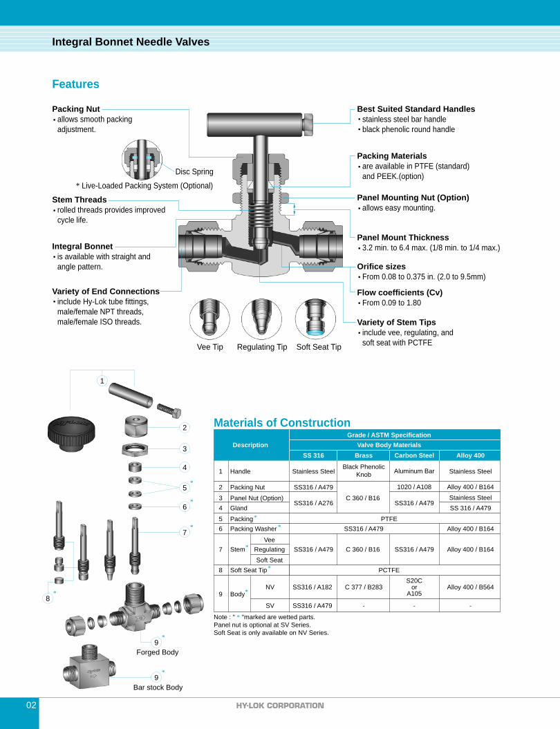
Packing Nut
Stem Threads
Packing Materials
Panel Mounting Nut (Option)
Variety of End Connections
Best Suited Standard Handles
Variety of Stem Tips
is available with straight andangle pattern.
stainless steel bar handleblack phenolic round handle
include vee, regulating, andsoft seat with PCTFE
allows smooth packing�adjustment.
are available in PTFE (standard)and PEEK.(option)
Integral Bonnet
include Hy-Lok tube fittings,male/female NPT threads,male/female ISO threads.
rolled threads provides improved �cycle life.
allows easy mounting.
Soft Seat TipRegulating TipVee Tip
Materials of Construction
Features
Panel Mount Thickness3.2 min. to 6.4 max. (1/8 min. to 1/4 max.)
Orifice sizesFrom 0.08 to 0.375 in. (2.0 to 9.5mm)
Flow coefficients (Cv)From 0.09 to 1.80
Forged Body
Bar stock Body
Note : " * "marked are wetted parts.�Panel nut is optional at SV Series.Soft Seat is only available on NV Series.
Grade / ASTM SpecificationValve Body Materials
SS 316Description
Alloy 400
1
SS316 / A479
SS316 / A276
Handle
SS316 / A479
SS316 / A479
Brass
2 Packing Nut
Packing
Soft SeatRegulating
Vee
Soft Seat Tip
Panel Nut (Option)
Body
56
7
8
3
9
Stainless Steel
NV
SV
Packing Washer
Carbon Steel
S20Cor
A105
-
1020 / A108
Stem
-
4 GlandSS316 / A479
SS 316 / A479
Aluminum Bar
SS316 / A479
PCTFE
PTFE
C 360 / B16
C 377 / B283
C 360 / B16
Alloy 400 / B164
Alloy 400 / B164
Alloy 400 / B164
Alloy 400 / B564
-
*
*
*
*
*
Stainless SteelBlack Phenolic
KnobStainless Steel
1
2
3
4
5
6
7
*
*
*
9*
8*
9*
SS316 / A182
SS316 / A479
* Live-Loaded Packing System (Optional)
Disc Spring
5000 (344)5000 (344)4380 (301)4080 (281)4010 (276)3940 (271)3940 (271)3940 (271)3940 (271)
3.4Carbon Steel
2500
03
Technical Data
Integral Bonnet Needle Valves
Material GroupMaterials
Temperature
ASME Class
-65°F (-54°C) to -20°F (-29°C) 100°F (38°C) 200°F (93°C) 300°F (148°C)350°F (176°C)400°F (204°C)450°F (232°C)500°F (260°C)600°F (316°C)
6000 (413)6000 (413)5160 (355)4660 (321)4470 (308)4280 (295)4130 (284)3980 (274)3760 (259)
3000 (206)3000 (206)2350 (161)2050 (141)1470 (101)
390 (26)-�-�-
-6000 (413)5420 (373)5320 (366)5230 (360)
-�-�-�-
Working Pressure (psig)
2.2 N/ABrass
2500 N/A
Alloy 400
To determine kPa, multiply psig by 6.89 and bar by 0.0689When valves with Hy-Lok Fitting end connections are connected to tubing, the working pressure of tubing must be the considered in the calculation of �total system working pressure�Extreme temperature fluctuations may require packing adjustment
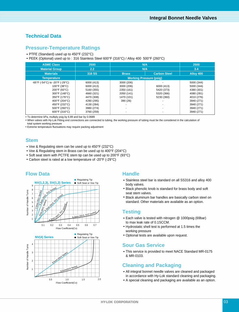
Flow Data
Num
ber o
f Han
dle
Turn
s
Flow Coefficient(Cv)
6.3mm (NV3, SV2 Series)
4.3mm (NV2, SV1 S
erie
s)
6.3mm (N
V3, SV2 S
eries)
4.3m
m (N
V2, S
V1 Series)
2.0m
m (N
V1 S
erie
s)2m
m (N
V1 S
eries
)
0.1 0.2
1
2
3
4
5
6
7
8
9
0.3 0.4 0.5 0.6 0.7
Regulating TipSoft Seat or Vee TipNV(1,2,3), SV(1,2) Series
Num
ber o
f Han
dle
Turn
s
Flow Coefficient(Cv)2.0
1
2
3
4
0.5 1.0 1.5
Regulating TipSoft Seat or Vee TipNV(4) Series
9.5mm (NV4 Series)
9.5mm(NV4 Series)
This service is provided to meet NACE Standard MR-0175 �& MR-0103.
Stainless steel bar is standard on all SS316 and alloy 400body valves.Black phenolic knob is standard for brass body and softseat stem valves.Black aluminum bar handles are basically carbon steel on standard. Other materials are available as an option.
Each valve is tested with nitrogen @ 1000psig (69bar)to max leak rate of 0.1SCCM.Hydrostatic shell test is performed at 1.5 times theworking pressureOptional tests are available upon request.
Sour Gas Service
All integral bonnet needle valves are cleaned and packaged �in accordance with Hy-Lok standard cleaning and packaging. A special cleaning and packaging are available as an option.
Cleaning and Packaging
Handle
Vee & Regulating stem can be used up to 450°F (232°C)�Vee & Regulating stem in Brass can be used up to 400°F (204°C)�Soft seat stem with PCTFE stem tip can be used up to 200°F (93°C)�Carbon steel is rated at a low temperature of -20°F (-29°C)
Stem
PTFE (Standard) used up to 450°F (232°C)�PEEK (Optional) used up to :316 Stainless Steel 600°F (316°C) / Alloy 400 500°F (260°C)
Pressure-Temperature Ratings
Testing
316 SS
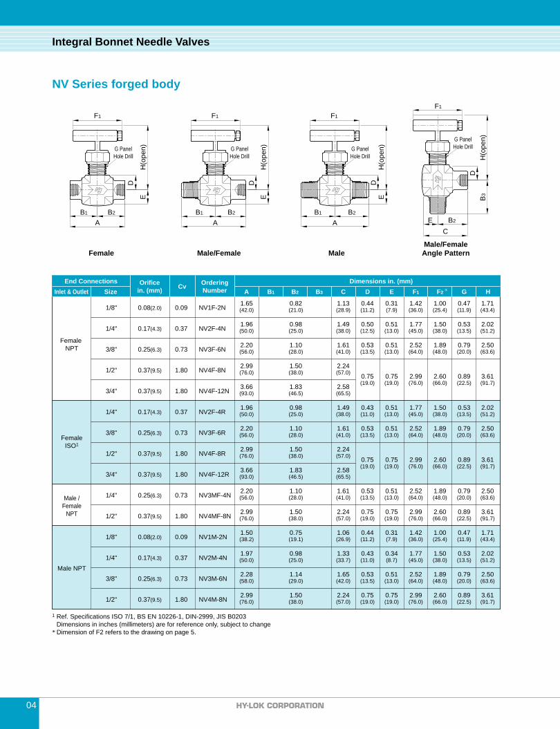
Female Male/Female Male
04
Integral Bonnet Needle Valves
NV Series forged body
1Ref. Specifications ISO 7/1, BS EN 10226-1, DIN-2999, JIS B0203 Dimensions in inches (millimeters) are for reference only, subject to change�*Dimension of F2 refers to the drawing on page 5.
Female NPT
FemaleISO1
Male /�Female
NPT
Male NPT
1/8"
1/4"
3/8"�
1/2"
3/4"
1/4"
3/8"�
1/2"
3/4"
1/4"
1/2"
1/8"�
1/4"
3/8"
1/2"
0.09
0.37
0.73
1.80
1.80
0.37
0.73
1.80
1.80
0.73
1.80
0.09
0.37
0.73
1.80
NV1F-2N
NV2F-4N
NV3F-6N
NV4F-8N
NV4F-12N
NV2F-4R
NV3F-6R
NV4F-8R
NV4F-12R
NV3MF-4N
NV4MF-8N
NV1M-2N
NV2M-4N
NV3M-6N
NV4M-8N
Dimensions in. (mm)A B1 B2 B3 C D E F1 F2 G H
CvOrifice�in. (mm)
OrderingNumber
End ConnectionsInlet & Outlet Size
0.08
0.17
0.25
0.37
0.37
0.17
0.25
0.37
0.37
0.25
0.37
0.08
0.17
0.25
0.37
1.65� 0.82 1.13 0.44 0.31 1.42 1.00 0.47 1.71
1.96 0.98 1.49 0.50 0.51 1.77 1.50 0.53 2.02
2.20� 1.10 1.61 0.53 0.51 2.52 1.89 0.79 2.50
2.99� 1.50 2.240.75 0.75 2.99 2.60 0.89 3.61
3.66 1.83 2.58
1.96 1.49 0.43 0.51 1.77 1.50 0.53 2.02
2.20�
0.98
1.10 1.61 0.53 0.51 2.52 1.89 0.79 2.50
2.99� 1.50 2.240.75 0.75 2.99 2.60 0.89 3.61
3.66 1.83 2.58
2.20 1.10 1.61 0.53 0.51 2.52 1.89 0.79 2.50
2.99 1.50 2.24 0.75 0.75 2.99 2.60 0.89 3.61
1.50 0.75 1.06 0.44 0.31 1.42 1.00 0.47 1.71
0.43 0.34 1.77 1.50 0.53 2.021.97 0.98 1.33
2.28 1.14 1.65 0.53 0.51 2.52 1.89 0.79 2.50
2.99 1.50 2.24 0.75 0.75 2.99 2.60 0.89 3.61
(2.0)
(4.3)
(6.3)
(9.5)
(9.5)
(4.3)
(6.3)
(9.5)
(9.5)
(6.3)
(9.5)
(2.0)
(4.3)
(6.3)
(9.5)
(42.0) (21.0) (28.9) (11.2) (7.9) (36.0) (25.4) (11.9) (43.4)
(50.0) (25.0) (38.0) (12.5) (13.0) (45.0) (38.0) (13.5) (51.2)
(56.0) (28.0) (41.0) (13.5) (13.0) (64.0) (48.0) (20.0) (63.6)
(76.0) (38.0) (57.0)
(19.0) (19.0) (76.0) (66.0) (22.5) (91.7)
(93.0) (46.5) (65.5)
(50.0) (38.0) (11.0) (13.0) (45.0) (38.0) (13.5) (51.2)
(56.0)
(25.0)
(28.0) (41.0) (13.5) (13.0) (64.0) (48.0) (20.0) (63.6)
(76.0) (38.0) (57.0)
(19.0) (19.0) (76.0) (66.0) (22.5) (91.7)
(93.0) (46.5) (65.5)
(56.0) (28.0) (41.0) (13.5) (13.0) (64.0) (48.0) (20.0) (63.6)
(76.0) (38.0) (57.0) (19.0) (19.0) (76.0) (66.0) (22.5) (91.7)
(38.2) (19.1) (26.9) (11.2) (7.9) (36.0) (25.4) (11.9) (43.4)
(11.0) (8.7) (45.0) (38.0) (13.5) (51.2)(50.0) (25.0) (33.7)
(58.0) (29.0) (42.0) (13.5) (13.0) (64.0) (48.0) (20.0) (63.6)
(76.0) (38.0) (57.0) (19.0) (19.0) (76.0) (66.0) (22.5) (91.7)
AB1 B2
E
D
H(o
pen)
F1
G Panel�Hole Drill
B1 B2
F1
A
E
D
H(o
pen)G Panel�
Hole Drill
B1 B2
F1
G Panel�Hole Drill
ED
H(o
pen)
A
Male/FemaleAngle Pattern
F1
G Panel�Hole Drill
B2
CE
B3
DH
(ope
n)

Male�Hy-Lok tube fitting Hy-Lok tube fitting
Hy-Lok tube fitting�Angle Pattern
Knob�Handle
F2
05
Integral Bonnet Needle Valves
NV Series forged body
Dimensions in inches (millimeters) are for reference only, subject to changeDimensions shown with Hy-Lok Nuts in finger-tight position, where applicable
Male NPTHy-Lok
tube fittings
FractionalHy-Lok
tube fittings
MetricHy-Lok
tube fittings
1/8"
1/4"
�
�
3/8"
1/8"
1/4"
3/8"
1/2"
�
3mm
6mm
8mm
10mm
12mm
0.08
0.17
0.17
0.25
0.25
0.08
0.17
0.25
0.25
0.08
0.17
0.17
0.25
0.25
0.09
0.37
0.37
0.73
0.73
0.09
0.37
0.73
0.73
0.09
0.37
0.37
0.73
0.73
1.72 0.75 0.96 0.75 1.29 0.44 0.31 1.42 1.00 0.47 1.71
2.12 0.98 1.130.98 1.65
0.43 0.51 1.50 0.53 2.020.98 1.35
2.41 1.101.31
1.101.82 0.53 0.51 1.89 0.79 2.50
2.45 1.14 1.14
0.44 0.31 1.00 0.47 1.711.93 1.27
2.27 1.65 0.43 0.51 1.50 0.53 2.02
2.61 1.82
2.83 1.930.53 0.51 1.89 0.79 2.50
0.75 0.75 2.60 0.89 3.613.81 2.66
0.44 0.31 1.00 0.47 1.711.93 1.27
2.27 1.530.43 0.39 1.50 0.53 2.02
2.33
2.61 1.82
1.56
1.930.53 0.51 1.89 0.79 2.50
2.83
0.75 0.75 2.60 0.89 3.613.04
0.96
1.13
1.31
1.42
1.91
0.96
1.13
1.17
1.31
1.42
1.52 2.27
(43.7) (19.1) (24.6) (19.1) (32.8) (11.2) (7.9) (36.0) (25.4) (11.9) (43.4)
(53.8) (25.0) (28.8)
(25.0) (41.8)
(11.0) (13.0) (38.0) (13.5) (51.2)
(25.0) (34.4)
(61.2) (28.0)
(33.2)
(28.0)
(46.2) (13.5) (13.0) (48.0) (20.0) (63.6)
(62.2) (29.0) (29.0)
(11.2) (7.9) (25.4) (11.9) (43.4)(49.2) (32.5)
(57.6) (41.8) (11.0) (13.0) (38.0) (13.5) (51.2)
(66.4) (46.2)
(72.0) (49.0)
(13.5) (13.0) (48.0) (20.0) (63.6)
(19.0) (19.0) (66.0) (22.5) (91.7)(97.0) (67.5)
(11.2) (7.9) (25.4) (11.9) (43.4)(49.2) (32.5)
(57.6) (38.8)
(11.0) (10.0) (38.0) (13.5) (51.2)
(59.2)
(66.4) (46.2)
(39.6)
(49.0)
(13.5) (13.0) (48.0) (20.0) (63.6)
(72.0)
(19.0) (19.0) (66.0)
1.77
2.52
1.42
1.77
2.52
2.99
1.42
1.77
2.52
2.99
(45.0)
(64.0)
(36.0)
(45.0)
(64.0)
(76.0)
(36.0)
(45.0)
(64.0)
(76.0) (22.5) (91.7)(77.2)
(24.6)
(28.8)
(33.2)
(36.0)
(48.5)
(24.6)
(28.8)
(29.6)
(33.2)
(36.0)
(38.6) (57.6)
NV1MH-2N2T
NV2MH-4N4T
NV2MH-4N6M
NV3MH-4N6T
NV3MH-6N6T
NV1H-2T
NV2H-4T
NV3H-6T
NV3H-8T
�
NV1H-3M
NV2H-6M
NV2H-8M
NV3H-10M
NV3H-12M
Dimensions in. (mm)A B1 B2 B3 C D E F1 F2 G H
CvOrifice�in. (mm)
OrderingNumber
End ConnectionsInlet & Outlet Size
1/2"3/4"
0.370.37
����������
0.370.37
(2.0)
(4.3)
(4.3)
(6.3)
(6.3)
(2.0)
(4.3)
(6.3)
(6.3)
(2.0)
(4.3)
(4.3)
(6.3)
(6.3)
(9.5)
(9.5)�
�
�
�
�
�
�
�
�
�
�
(9.5)
(9.5)
16mm18mm
1.801.80
1.801.80
NV4H-8T NV4H-12T
NV4H-16M NV4H-18M
1/4" Male NPT6.0mm Hy-Lok
1/4" Male NPT3/8" Hy-Lok
ED
H(o
pen)G Panel�
Hole Drill
F1
A
B1 B2
G Panel�Hole Drill
F1
B1 B2
ED
H(o
pen)
A
G Panel�Hole Drill
F1
B2
CE
B3
DH
(ope
n)

Female MaleMale / Female
Hy-Lok tube fittingMale�
Hy-Lok tube fittingMale / Female�Angle Pattern
EH
(ope
n)
AB1 B2
F
EH
(ope
n)
AB1 B2
F
EH
(ope
n)
AB1 B2
F
AB1 B2
EH
(ope
n)
F
EH
(ope
n)
AB1 B2
F
H(o
pen)
B4
CE
B3
F
SV Series barstock body
FemaleNPT
1/4"
3/8"
1/2"
1/4"
3/8"
1/2"
1/4"
3/8"
1/2"
0.13
0.25
0.25
0.13
0.25
0.25
0.13
0.25
0.25
(3.2)
(6.3)
(6.3)
(3.2)
(6.3)
(6.3)
(3.2)
(6.3)
(6.3)
0.37
0.73
0.73
0.37
0.73
0.73
0.37
0.73
0.73
1.87 0.94 0.94
2.50 1.25 1.25
0.44 1.77 1.711.00 1.00 1.44
0.66 2.52 2.481.25 1.25 1.91
2.50 1.25 1.25 0.66 2.52 2.481.22
1.411.25 1.91
1.87 0.97 0.97 0.99 0.44 1.77 1.710.97 1.41
2.20 0.97 1.23 0.99 0.44 1.77 1.711.13 1.57
2.46 1.23 1.23 1.17 0.44 1.77 1.711.13 1.57
3.08 1.54 1.54 1.250.66 2.52 2.48
1.25 1.91
3.30 1.65 1.65 - - -
1.91 0.97 0.94 0.44 1.77 1.711.03 1.00 1.44
SV1F-4N
SV2F-6N
SV2F-8N
SV1MF-4N
SV2MF-6N
SV2MF-8N
SV1H-4T
SV2H-6T
SV2H-8T
0.13��
0.13
(3.2)�
�
�
(3.2)
0.37���
0.37
SV1M-4N��SV1MH-4N4T
1/4" Male NPT1/4" Hy-Lok
Dimensions in. (mm)A B1 B2 B3 B4 C E F H
CvOrifice�in. (mm)
OrderingNumber
End ConnectionsInlet & Outlet Size
Male /�Female
NPT
Male NPT
Male NPT/Hy-Lok
tube fittings
Hy-LoKtube fittings
Dimensions in inches (millimeters) are for reference only, subject to changeDimensions shown with Hy-Lok Nuts in finger-tight position, where applicable
06
Integral Bonnet Needle Valves
1/4"
(47.6) (23.8) (23.8)
(63.6) (31.8) (31.8)
(11.2) (45.0) (43.5)(25.4) (25.4) (36.5)
(16.8) (64.0) (63.0)(31.8) (31.8) (48.6)
(63.6) (31.8) (31.8) (16.8) (64.0) (63.0)
(31.0)
(35.8)
(31.8) (48.6)
(49.2) (24.6) (24.6) (25.2) (11.2) (45.0) (43.5)(24.6) (35.8)
(55.8) (24.6) (31.2) (25.2) (11.2) (45.0) (43.5)(28.7) (39.8)
(62.4) (31.2) (31.2) (29.7) (11.2) (45.0) (43.5)(28.7) (39.8)
(78.2) (39.1) (39.1) (31.8)
(16.8) (64.0) (63.0)
(31.8) (48.6)
(83.8) (41.9) (41.9)
(48.4) (24.6) (23.8) (11.2) (45.0) (43.5)(26.2) (25.4) (36.5)

07
Integral Bonnet Needle Valves
For non-standard not shown in dimension table, it can be used by assembling Hy-Lok tube fittings to standard products. This use of way is easily available to the construction of system, especially it is more reasonable in aspects of delivery and purchasing costs. For the more information and types of connector, please refer to the Hy-Lok Tube Fitting Catalog.
Use of Non-Standard Products
NV3 F A 6N S PK K FE SOG S316P
Tube O.D. Designation
Pipe Thread Designation NPT ( ISO / BSP )
Series DesignatorNVSV**
: NV Series: SV Series
Body Pattern�Designator
Nil
A
: Straight Pattern (Standard): Angle Pattern
Stem Packing�Designator
Nil�PK
: PTFE� (Standard): PEEK
Sour Gas ServiceNil�SOG
: without� (Standard): NACE MR-01-75
Panel Mounting Nut DesignatorNilP
: Without (Standard): Panel Mounting Nut
Nil�FE
: without� (Standard): Live Loaded� System
Material Designator S316BRASSTELMONE
: 316 Stainless Steel: Brass: Carbon Steel: Alloy 400 (Monel)
Handle DesignatorNilK
: Stainless Steel Bar (Standard): Black Phenolic Knob Available only with Soft Seat Tip
Stem Tip DesignatorNilRS
: Vee (Standard): Regulating: Soft Seat with PCTFE
End Connector Designator: Both Ends Female Pipe Thread: Both Ends Male Pipe Thread: Both Ends Hy-Lok Tube Fitting: Male Pipe Thread and Female Pipe Thread: Male Pipe Thread and Hy-Lok Tube Fitting
F M H MF
MH
Size Designator
Note : No designator is required for standard e.g. NV3F-6N-S316
Tube O.D.�Designation�Tube O.D.
Designation
1/8"�2T�
3mm�3M
1/4"�4T�
6mm�6M
3/8"�6T�
10mm�10M
1/2"�8T�
12mm�12M
3/4"�12T�
18mm�18M
Nom. Size�Designator
1/8"�2N(R)
1/4"�4N(R)
3/8"�6N(R)
1/2"�8N(R)
3/4"�12N(R)
InchTube
MetricTube
Ordering Information
Note :This figure is only for reference, please refer to Hy-Lok tube fittings catalog for varios connection.
Example of Connection Standard Product Ends
Female Adapter Male Adapter

Hy-Lok Coporation�97, Noksansandan 27-ro, Gangseo-gu,�Busan, South Korea�Phone 82 51 9700 800�Fax 82 51 831 7920�Visit www.hy-lok.com or�contact your authorized Hy-Lok representative.
Proper installation, materials compatibility, operation and maintenance of these valves are the responsibility of the user.The total system design must be taken into considerationto ensure optimal performance and safety
SAFETY in VALVE SELECTION
www.hy-lok.com