Variable stiffness design of redundantly actuated planar ... · Abstract Redundantly actuated...
9
1 2 REVIEW ARTICLE 4 Variable stiffness design of redundantly actuated 5 planar rotational parallel mechanisms 6 Li Kangkang, Jiang Hongzhou * , Cui Zuo, Huang Qun 7 School of Mechatronics Engineering, Harbin Institute of Technology, Harbin 150001, China 8 Received 6 March 2016; revised 25 March 2016; accepted 12 June 2016 9 11 KEYWORDS 12 13 Internal force; 14 Parallel mechanisms; 15 Redundantly actuated; 16 Robustness; 17 Variable stiffness Abstract Redundantly actuated planar rotational parallel mechanisms (RAPRPMs) adapt to the requirements of robots under different working conditions by changing the antagonistic internal force to tune their stiffness. The geometrical parameters of the mechanism impact the performances of modulating stiffness. Analytical expressions relating stiffness and geometrical parameters of the mechanism were formulated to obtain the necessary conditions of variable stiffness. A novel method of variable stiffness design was presented to optimize the geometrical parameters of the mechanism. The stiffness variation with the internal force was maximized. The dynamic change of stiffness with the dynamic location of the mechanism was minimized, and the robustness of stiff- ness during the motion of the mechanism was ensured. This new approach to variable stiffness design can enable off-line planning of the internal force to avoid the difficulties of on-line control of the internal force. Ó 2016 Chinese Society of Aeronautics and Astronautics. Production and hosting by Elsevier Ltd. This is an open access article under the CC BY-NC-ND license (http://creativecommons.org/licenses/by-nc-nd/4.0/). 18 19 1. Introduction 20 Planar parallel manipulators perform two translations along 21 the x- and y-axes, and rotate through an angle around the z- 22 axis, perpendicular to the plane. They have some potential 23 advantages over serial robotic manipulators such as better 24 accuracy, greater load capacity, and higher velocity and accel- 25 eration. 1,2 The redundantly actuated planar rotational parallel 26 mechanism (RAPRPM) is a special type of planar parallel 27 manipulator. It does not have the ability to move along the 28 x- and y-axes, and only has a single degree of freedom, rotat- 29 ing around the z-axis. Meanwhile, the stiffness of rotation 30 around the z-axis can be modulated by employing redundant 31 actuation. The performances including inverse kinematics, 32 forward kinematics, Jacobian matrix, workspace, singularity, 33 and dexterity of planar parallel manipulators have been ana- 34 lyzed. 1–4 Stiffness modeling of a robotic manipulator is also 35 one of the important issues that allows a user to evaluate its 36 compatibility for certain tasks. 5 Based on biological studies 37 of the muscular properties and the skeletal structures of fish, 38 Cui and Jiang presented a robotic fish consisting of planar 39 serial-parallel mechanisms, i.e., the RAPRPMs connecting to 40 each other in series. It included rigid bodies, springs, dampers, 41 and revolution joints. Their results showed that the swimming * Corresponding author. E-mail addresses: [email protected] (K. Li), jianghz@hit. edu.cn (H. Jiang), [email protected] (Z. Cui), [email protected] (Q. Huang). Peer review under responsibility of Editorial Committee of CJA. Production and hosting by Elsevier Chinese Journal of Aeronautics, (2016), xxx(xx): xxx–xxx Chinese Society of Aeronautics and Astronautics & Beihang University Chinese Journal of Aeronautics [email protected] www.sciencedirect.com http://dx.doi.org/10.1016/j.cja.2016.07.001 1000-9361 Ó 2016 Chinese Society of Aeronautics and Astronautics. Production and hosting by Elsevier Ltd. This is an open access article under the CC BY-NC-ND license (http://creativecommons.org/licenses/by-nc-nd/4.0/). CJA 691 No. of Pages 9 25 October 2016 Please cite this article in press as: Li K et al. Variable stiffness design of redundantly actuated planar rotational parallel mechanisms, Chin J Aeronaut (2016), http:// dx.doi.org/10.1016/j.cja.2016.07.001
Transcript of Variable stiffness design of redundantly actuated planar ... · Abstract Redundantly actuated...
1
2
4
5
6
7
8
9
1112
13
14
15
16
17
18
19
20
21
22
23
24
Chinese Journal of Aeronautics, (2016), xxx(xx): xxx–xxx
CJA 691 No. of Pages 9
25 October 2016
Chinese Society of Aeronautics and Astronautics& Beihang University
Chinese Journal of Aeronautics
REVIEW ARTICLE
Variable stiffness design of redundantly actuated
planar rotational parallel mechanisms
* Corresponding author.
E-mail addresses: [email protected] (K. Li), jianghz@hit.
edu.cn (H. Jiang), [email protected] (Z. Cui), [email protected]
(Q. Huang).
Peer review under responsibility of Editorial Committee of CJA.
Production and hosting by Elsevier
http://dx.doi.org/10.1016/j.cja.2016.07.0011000-9361 � 2016 Chinese Society of Aeronautics and Astronautics. Production and hosting by Elsevier Ltd.This is an open access article under the CC BY-NC-ND license (http://creativecommons.org/licenses/by-nc-nd/4.0/).
Please cite this article in press as: Li K et al. Variable stiffness design of redundantly actuated planar rotational parallel mechanisms, Chin J Aeronaut (2016dx.doi.org/10.1016/j.cja.2016.07.001
Li Kangkang, Jiang Hongzhou *, Cui Zuo, Huang Qun
School of Mechatronics Engineering, Harbin Institute of Technology, Harbin 150001, China
Received 6 March 2016; revised 25 March 2016; accepted 12 June 2016
KEYWORDS
Internal force;
Parallel mechanisms;
Redundantly actuated;
Robustness;
Variable stiffness
Abstract Redundantly actuated planar rotational parallel mechanisms (RAPRPMs) adapt to the
requirements of robots under different working conditions by changing the antagonistic internal
force to tune their stiffness. The geometrical parameters of the mechanism impact the performances
of modulating stiffness. Analytical expressions relating stiffness and geometrical parameters of the
mechanism were formulated to obtain the necessary conditions of variable stiffness. A novel
method of variable stiffness design was presented to optimize the geometrical parameters of the
mechanism. The stiffness variation with the internal force was maximized. The dynamic change
of stiffness with the dynamic location of the mechanism was minimized, and the robustness of stiff-
ness during the motion of the mechanism was ensured. This new approach to variable stiffness
design can enable off-line planning of the internal force to avoid the difficulties of on-line control
of the internal force.� 2016 Chinese Society of Aeronautics and Astronautics. Production and hosting by Elsevier Ltd. This is
an open access article under the CCBY-NC-ND license (http://creativecommons.org/licenses/by-nc-nd/4.0/).
25
26
27
28
29
30
31
1. Introduction
Planar parallel manipulators perform two translations alongthe x- and y-axes, and rotate through an angle around the z-axis, perpendicular to the plane. They have some potential
advantages over serial robotic manipulators such as betteraccuracy, greater load capacity, and higher velocity and accel-
32
33
34
35
36
37
38
39
40
41
eration.1,2 The redundantly actuated planar rotational parallel
mechanism (RAPRPM) is a special type of planar parallelmanipulator. It does not have the ability to move along thex- and y-axes, and only has a single degree of freedom, rotat-
ing around the z-axis. Meanwhile, the stiffness of rotationaround the z-axis can be modulated by employing redundantactuation. The performances including inverse kinematics,forward kinematics, Jacobian matrix, workspace, singularity,
and dexterity of planar parallel manipulators have been ana-lyzed.1–4 Stiffness modeling of a robotic manipulator is alsoone of the important issues that allows a user to evaluate its
compatibility for certain tasks.5 Based on biological studiesof the muscular properties and the skeletal structures of fish,Cui and Jiang presented a robotic fish consisting of planar
serial-parallel mechanisms, i.e., the RAPRPMs connecting toeach other in series. It included rigid bodies, springs, dampers,and revolution joints. Their results showed that the swimming
), http://
42
43
44
45
46
47
48
49
50
51
52
53
54
55
56
57
58
59
60
61
62
63
64
65
66
67
68
69
70
71
72
73
74
75
76
77
78
79
80
81
82
83
84
85
86
87
88
89
90
91
92
93
94
95
96
97
98
99
100
101
102
103
104
105
106
107
108
109
110
111
112
113
114
115
116
117
118
119
120
121
122
123
124
125
126
127
128
129
130
131
132
133
134
135
136
137
138
139
140
142142
143
Fig. 1 Compliant fish with serial-parallel redundantly actuated
mechanisms.
2 K. Li et al.
CJA 691 No. of Pages 9
25 October 2016
performance of the robotic fish was largely dependent on thebody stiffness and the driven frequency.6 Biological experi-ments of fish have shown that fish change their natural fre-
quency by modulating the stiffness of their bodies to matchthe driving frequency. Then fish can employ resonance toimprove their swimming efficiency.7–9 Swimming fish that
can tune their body stiffness by appropriately timed musclecontractions are able to maximize peak acceleration or swim-ming speed. The muscles are modeled as springs of constant
stiffness.10 To study the body stiffness of robotic fish consist-ing of planar serial-parallel mechanisms, it is important tostudy the stiffness design and stiffness control of theRAPRPM. Stiffness control schemes realized by employing
redundant actuation can be broadly categorized as: passivestiffness control (PSC), feedback stiffness control (FSC), andactive stiffness control (ASC).11,12 PSC is a scheme that
changes the stiffness of the mechanism by adding flexible ele-ments to the original mechanism.13,14 Because the stiffness offlexible elements cannot be changed much, the stiffness of
the mechanism is changed less by using PSC. An FSC schemechooses proportional coefficients in the positioning joint con-trollers that correspond to the desired characteristics for con-
trol of the end-effector.15,16 However, the modulation ofproportional coefficients of controllers may make the systemunstable. An ASC scheme yields antagonistic forces in a redun-dantly actuated mechanism. The internal forces balance each
other in a closed mechanism and do not perform any effectivework, but generate end-effector stiffness.17–20 An ASC schemecan significantly modulate the stiffness by modulating the
internal force, which involves off-line planning of antagonisticactuator loads, so that one can obtain the desired object stiff-ness.21–24 An ASC scheme is chosen to control the stiffness of
the RAPRPM because of its advantages over other stiffnesscontrol schemes.
In addition, it is also meaningful to apply an ASC scheme
to maintain constant stiffness and maximize the change ofstiffness with the internal force. Sungcheul et al. introducedtwo indexes, one of which was suggested to make the minimumstiffness similar to the maximum stiffness at a given point and
to ensure robustness and balance of the stiffness in all direc-tions. The other index was used to maximize the stiffness ina fixed direction along the pathway.25 Hence, for the
RAPRPM whose stiffness changes with the dynamic locationof a platform, applying an ASC scheme to enable on-line con-trol of the internal force according to the dynamic location to
keep the stiffness constant and to maximize the change of stiff-ness with the internal force, would increase the controlling dif-ficulty and responding time. However, when applying an ASCscheme to enable off-line planning of the internal force to
avoid the difficulties of on-line control, geometrical parametersare required to meet the following three requirements. Firstly,the amount of active stiffness variation with the internal force
is maximum. Secondly, the proportion of active stiffness intotal stiffness is maximum. Thirdly, the dynamic change ofactive stiffness with the rotating angle is minimum to ensure
the robustness of stiffness during movement of the platform.In addition, optimization strategies such as particle swarmoptimization and genetic algorithms have been widely used
to minimize the power requirement for a planar parallelmanipulator,26 to compensate for compliance errors,5 toobtain superior dexterous workspace,27,28 or to maximize stiff-ness.29,30 Similarly, the geometrical parameters are optimized
Please cite this article in press as: Li K et al. Variable stiffness design of redundantlydx.doi.org/10.1016/j.cja.2016.07.001
to maximize the stiffness variation with the internal forceand minimize the dynamic changes of total stiffness with thedynamic location of the mechanism.
2. Torsional stiffness of RAPRPM
2.1. Variable stiffness principle of RAPRPM
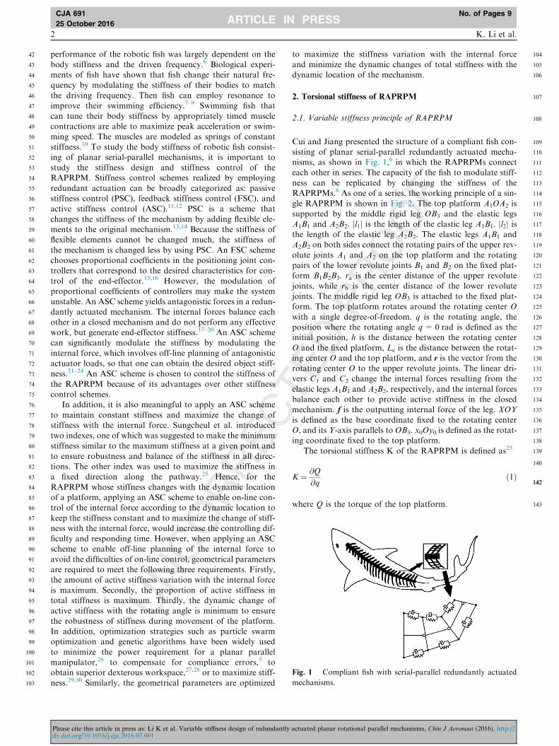
Cui and Jiang presented the structure of a compliant fish con-
sisting of planar serial-parallel redundantly actuated mecha-nisms, as shown in Fig. 1,6 in which the RAPRPMs connecteach other in series. The capacity of the fish to modulate stiff-
ness can be replicated by changing the stiffness of theRAPRPMs.6 As one of a series, the working principle of a sin-gle RAPRPM is shown in Fig. 2. The top platform A1OA2 is
supported by the middle rigid leg OB3 and the elastic legsA1B1 and A2B2. jl1j is the length of the elastic leg A1B1. jl2j isthe length of the elastic leg A2B2. The elastic legs A1B1 andA2B2 on both sides connect the rotating pairs of the upper rev-
olute joints A1 and A2 on the top platform and the rotatingpairs of the lower revolute joints B1 and B2 on the fixed plat-form B1B2B3. ra is the center distance of the upper revolute
joints, while rb is the center distance of the lower revolutejoints. The middle rigid leg OB3 is attached to the fixed plat-form. The top platform rotates around the rotating center O
with a single degree-of-freedom. q is the rotating angle, theposition where the rotating angle q = 0 rad is defined as theinitial position, h is the distance between the rotating center
O and the fixed platform, Lc is the distance between the rotat-ing center O and the top platform, and r is the vector from therotating center O to the upper revolute joints. The linear dri-vers C1 and C2 change the internal forces resulting from the
elastic legs A1B1 and A2B2, respectively, and the internal forcesbalance each other to provide active stiffness in the closedmechanism. f is the outputting internal force of the leg. XOY
is defined as the base coordinate fixed to the rotating centerO, and its Y-axis parallels to OB3. x0Oy0 is defined as the rotat-ing coordinate fixed to the top platform.
The torsional stiffness K of the RAPRPM is defined as25
K ¼ @Q
@qð1Þ
where Q is the torque of the top platform.
actuated planar rotational parallel mechanisms, Chin J Aeronaut (2016), http://

144
145146
148148
149
150
151152
154154
155
156
157
158159
161161
162
163
164165
167167
168
169
170
171172
174174
175176
178178
179
180
181182
184184
185
186
187
188
189
190
191
192
193194
196196
197
198
199
200
201
202203
205205
206
207
208
209
210211
213213
214
215
216
217
218219
221221
222
223224
226226
227
228
229230
232232
233
234
235
236
237
238239
Fig. 2 Schematic of a single parallel mechanism.
Variable stiffness design of redundantly actuated planar rotational parallel mechanisms 3
CJA 691 No. of Pages 9
25 October 2016
As shown in Fig. 2, the torque Q of the top platform is
defined as follows:
Q ¼ rTEf ð2Þwhere r= [x, y]T. E is the two-dimensional rotational matrix,
and E ¼ 0 1�1 0
� �. The components of the internal force f are
fx and fy, which can be written as
f ¼ ½fx; fy�T ¼ f0ln ð3Þwhere f0 is the amount of the internal force. ln is the unit vector
of the elastic leg, and ln ¼ ljlj, in which l is the vector of the elas-
tic leg and jlj is the length of the elastic leg.By substituting Eq. (2) into Eq. (1), the torsional stiffness is
K ¼ @ rTEfð Þ@q
¼ @rT
@qEfþ rTE
@f
@qð4Þ
Stiffness consists of active stiffness and passive stiffness. Bysubstituting Eq. (3) into Eq. (4), the torsional stiffness K can
be expressed as:
K ¼ f0@rT
@qEln þ rTE
@ln@q
� �þ rTEln
@f0@q
ð5Þ
where the first item is the active stiffness Ka resulting from theinternal force of the mechanisms and the second item is the
passive stiffness Kp caused by the location. Hence, the activestiffness can be given by25
Ka ¼ f0@rT
@qEln þ rTE
@ln@q
� �ð6Þ
The passive stiffness is31
Kp ¼ rTEln@f0@q
¼ @f0@k
@k@q
� �rTEln ð7Þ
where k is the stretch-shortening length of the elastic leg,@k@q¼ rTEln,
@f0@k ¼ k0, and k0 is the stiffness of the elastic leg.
Therefore the passive stiffness Kp can be found from Eq. (7) as
Kp ¼ k0 rTEln� �2 ð8Þ
241241
242
243
244
245
246
2.2. Active stiffness of RAPRPM
As shown in Fig. 2, the torque Q of the mechanisms consists ofthe torque Q1 caused by the elastic leg A1B1 acting on the topplatform and the torque Q2 caused by the elastic leg A2B2 act-
Please cite this article in press as: Li K et al. Variable stiffness design of redundantlydx.doi.org/10.1016/j.cja.2016.07.001
ing on the top platform. That is, Q= Q1 + Q2. Hence, thetotal torsional stiffness K of the mechanisms consists of thetorsional stiffness K1 resulting from the elastic leg A1B1 and
the torsional stiffness K2 resulting from the elastic leg A2B2.The total torsional stiffness K is expressed as
K ¼ K1 þ K2 ð9ÞHence, the active stiffness and passive stiffness resulting
from elastic legs A1B1 and A2B2 must firstly be solved beforesolving the total torsional stiffness K of the mechanisms.
As shown in Fig. 2, r1 is the vector between the rotating
center O and the point of action A1 of the internal force f1,and r1 = [x, y]T, which can be described as
r1 ¼ ROA1
��! ð10Þwhere R is the matrix for coordinate transformation from the
rotating coordinate x0Oy0 to the fixed coordinate XOY.
R ¼ cos q � sin qsin q cos q
� �.32,33 In coordinate x0Oy0,
OA1
��! ¼ �raLc
� �.
The vector of the elastic leg A1B1 is
l1 ¼ B3O��!þ r1 � B3B1
���! ð11Þ
where B3O��! ¼ 0
l0 � Lc
� �, B3B1���! ¼ �rb
0
� �, l0 is the total height
from the fixed platform to the top platform at the initial posi-tion, and l0 ¼ Lc þ h.
The vector l1 of the elastic leg A1B1 can be derived from Eq.(11) as below31:
l1 ¼ x1½ ; y1�T
¼ �ra cos q� Lc sin qþ rb½ ;�ra sin qþ Lc cos qþ l0 � Lc�Tð12Þ
The vector between the rotating center O and the point ofaction A2 of the internal force f2 is shown as follows:
r2 ¼ ROA2
��! ð13Þ
where OA2
��! ¼ raLc
� �in coordinate x0Oy0.
Similarly, the vector l2 of the elastic leg A2B2 is expressed as
follows:
l2 ¼ ½x2; y2�T
¼ ra cos q� Lc sin q� rb;½ ra sin qþ Lc cos qþ l0 � Lc�T ð14ÞThe torque Q1 resulting from the elastic leg A1B1 acting on
the top platform and the torque Q2 resulting from the elastic
leg A2B2 acting on the top platform are in equilibrium, thatis, Q1 + Q2 = 0. Therefore, the amount of internal forcecaused by the elastic leg A2B2 can be derived from Eq. (2) as
follows:
f20 ¼�rT1El1nf10rT2El2n
ð15Þ
where f10 is the amount of internal force caused by the elasticleg A1B1, l1n is the unit vector of the elastic leg A1B1, and l2n is
the unit vector of the elastic leg A2B2.The active stiffness resulting from the elastic leg A1B1 can
be found by substituting Eqs. (10) and (12) into Eq. (6) as:
actuated planar rotational parallel mechanisms, Chin J Aeronaut (2016), http://
247
249249
250
251252
254254
255
256
257
258
259260
262262
263
264
265
266
267
268
269
270
271
272
273
274
275
276277
279279
280
281
282
283
284
285
286
287
288
289290
292292
293
294
295
296
297
298
299
300
301
302
303
304
305306
308308
309
310
311
312313
315315
316
317
318
319320
322322
323
324325
327327
328
329
330331
333333
334
335
336
337
338
339
340
341342
344344
345
346
347
348349
351351
352
353
354
355356
358358
4 K. Li et al.
CJA 691 No. of Pages 9
25 October 2016
K1aq ¼ @rT1@q
Ef10l1n þ rT1Ef10@l1n@q
ð16Þ
The active stiffness resulting from the elastic leg A1B1 at theinitial position is derived from Eq. (16) as
K1a ¼ f10
jl10j3�l20L
2c þ Lcl0 l20 þ r2b � r2a
� �þ l20raðra � rbÞ
�rarbðra � rbÞ2i
ð17Þ
where jl10j is the length of the elastic leg A1B1 at the initial posi-
tion; consequently, from Eq. (12), jl10j ¼ffiffiffiffiffiffiffiffiffiffiffiffiffiffiffiffiffiffiffiffiffiffiffiffiffiffiffiffiðra � rbÞ2 þ l20
q.
Similarly, the active stiffness resulting from the elastic legA2B2 can be given as follows by substituting Eqs. (13) and(14) into Eq. (6):
K2aq ¼ @rT2@q
Ef20l2n þ rT2Ef20@l2n@q
ð18Þ
The stiffness k10 of the elastic leg A1B1 is designed to be
equal to the stiffness k20 of the elastic leg A2B2, that is,
k10 = k2
0. Meanwhile, the length of the elastic leg A1B1 is equalto that of the elastic leg A2B2 at the initial position, that is,
jl10j ¼ jl20j. As is found from Eq. (15), the amount f10 of theinternal force caused by the elastic leg A1B1 is equal to theamount f20 of the internal force caused by the elastic leg
A2B2, that is, f10 = f20. As is found from Eqs. (16) and (18),the active stiffness K1a of the elastic leg A1B1 is equal to theactive stiffness K2a of the elastic leg A2B2, that is, K1a = K2a.
The total active stiffness Ka of the mechanisms at the initialposition is the sum of the active stiffness K1a and the activestiffness K2a. That is, Ka ¼ 2K1a. According to Eqs. (9) and(17), the total active stiffness is described as
Ka ¼ 2f10
jl10j3�l20L
2c þ Lcl0 l20 þ r2b � r2a
� �þ l20raðra � rbÞ � rarbðra � rbÞ2h i
ð19ÞAs is found from Eq. (19), the active stiffness Ka = 0 when
ra = rb with Lc = 0 mm or Lc = l0, i.e., the internal force can-
not tune the total torsional stiffness when the center distanceof the upper revolute joints is equal to the center distance ofthe lower revolute joints when the rotating center is on the
top platform or on the fixed platform. The condition of theinternal force tuning the stiffness is to avoid the situation. Inaddition, Eq. (19) is a quadratic function of Lc, therefore,
derived from Eq. (19), the amount of active stiffness Ka is max-imum when Lc meets the following requirement:
Lc ¼ ðrb � raÞðrb þ raÞ=ð2l0Þ þ l0=2 ð20ÞHence, Lc in Eq. (20) is the geometrical parameter that
maximizes the amount of stiffness variation with the internal
force.DKa is the difference between the maximum active stiffness
Kamax and the minimum active stiffness Kamin during the rota-
tion of the platform. Ka0 is the active stiffness at the initialposition. The ratio DKa/Ka0 is the maximum change of theactive stiffness Ka during the rotation of the platform. Derived
from Eqs. (16) and (18), as the center distance ra of the upperrevolute joints or the center distance rb of the lower revolutejoints increases, the maximum change of the active stiffness
Ka during the rotation of the platform decreases.The internal force of the elastic leg can be given as follows:
Please cite this article in press as: Li K et al. Variable stiffness design of redundantlydx.doi.org/10.1016/j.cja.2016.07.001
f10 ¼ k01cjl10j ð21Þwhere c is the ratio of the stretch-shortening length to the totallength of the elastic leg.
The active stiffness is derived as follows by substituting Eq.
(21) into Eq. (19):
Ka ¼ 2k01c
jl10j2�l20L
2c þ Lcl0 l20 þ r2b � r2a
� �þ l20raðra � rbÞ � rarbðra � rbÞ2h i
ð22Þ
2.3. Passive stiffness of RAPRPM
The passive stiffness resulting from the elastic leg A1B1 isderived by substituting Eqs. (10) and (12) into Eq. (8) asfollows:
K1pq ¼ k01 rT1El1n� �2 ð23Þ
The passive stiffness at the initial position is derived fromEq. (23) as follows:
K1p ¼ k01½ðl0 � LcÞra þ rbLc�2jl10j2
ð24Þ
Similarly, the passive stiffness resulting from the elastic leg
A2B2 is derived as follows by substituting Eqs. (13) and (14)into Eq. (8):
K2pq ¼ k02 rT2El2n� �2 ð25Þ
It can be derived from Eqs. (23) and (25) that the passivestiffness K1p resulting from the elastic leg A1B1 is equal to
the passive stiffness K2p resulting from the elastic leg A2B2 atthe initial position. That is, K1p = K2p.
The total passive stiffness Kp of the mechanisms at the ini-
tial position is the sum of the two passive stiffness K1p and K2p.That is, Kp = 2K1p. According to Eqs. (9) and (24), the totalpassive stiffness is given as
Kp ¼ 2k01½ðl0 � LcÞra þ rbLc�2jl10j2
ð26Þ
2.4. Total stiffness of RAPRPM
The total stiffness K at the initial position is the sum of thetotal active stiffness Ka and the total passive stiffness Kp, whichcan be derived from Eqs. (5), (19), and Eq. (26) as:
K ¼ 2f10
jl10j3�l20L
2c þ Lcl0 l20 þ r2b � r2a
� �þ l20raðra � rbÞ � rarbðra � rbÞ2h i
þ 2k01½ðl0 � LcÞra þ rbLc�2
jl10j2ð27Þ
In the case of Eq. (20), the amount of active stiffness vari-ation with the internal force is maximum. The ratio of active to
passive stiffness at the initial position is derived from Eqs. (22)and (26) as:
Ka
Kp
¼ c l40 þ r4a þ 6r2ar2b þ r4b þ 2l20r
2b þ 2l20r
2a � 4l20rarb � 4r3arb � 4rar
3b
� �l0ðra þ rbÞ þ ðrbþraÞðra�rbÞ2
l0
h i2ð28Þ
actuated planar rotational parallel mechanisms, Chin J Aeronaut (2016), http://
359
360
361
362
363
364
365
366
367
368
369
370
371
372
373
374
375
376
377
378
379
380
381
382
383
384
385
386
387
388
389
390
391
392
393394
396396
397
398
399
400
401
402
403
404
405
406
407
408
409
410
411
412
413
414
415
416
417
418
419
420
421
422
423
424
425
426
427
428
429
430
431
432
433
434
435
436
437
438
439
440
441
442
443
444
445
446
447
448
449
450
451
452
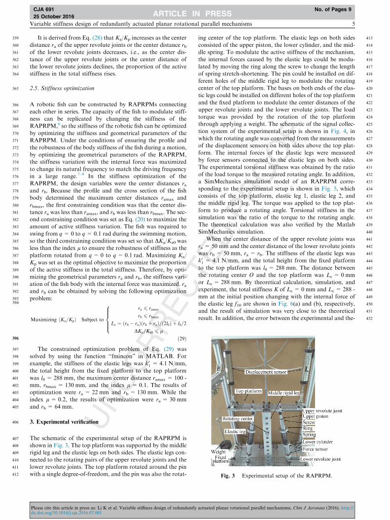
Fig. 3 Experimental setup of the RAPRPM.
Variable stiffness design of redundantly actuated planar rotational parallel mechanisms 5
CJA 691 No. of Pages 9
25 October 2016
It is derived from Eq. (28) that Ka/Kp increases as the centerdistance ra of the upper revolute joints or the center distance rbof the lower revolute joints decreases, i.e., as the center dis-
tance of the upper revolute joints or the center distance ofthe lower revolute joints declines, the proportion of the activestiffness in the total stiffness rises.
2.5. Stiffness optimization
A robotic fish can be constructed by RAPRPMs connecting
each other in series. The capacity of the fish to modulate stiff-ness can be replicated by changing the stiffness of theRAPRPM,6 so the stiffness of the robotic fish can be optimized
by optimizing the stiffness and geometrical parameters of theRAPRPM. Under the conditions of ensuring the profile andthe robustness of the body stiffness of the fish during a motion,by optimizing the geometrical parameters of the RAPRPM,
the stiffness variation with the internal force was maximizedto change its natural frequency to match the driving frequencyin a large range.7–9 In the stiffness optimization of the
RAPRPM, the design variables were the center distances raand rb. Because the profile and the cross section of the fishbody determined the maximum center distances ramax and
rbmax, the first constraining condition was that the center dis-tance ra was less than ramax, and rb was less than rbmax. The sec-ond constraining condition was set as Eq. (20) to maximize theamount of active stiffness variation. The fish was required to
swing from q= 0 to q = 0.1 rad during the swimming motion,so the third constraining condition was set so that DKa/Ka0 wasless than the index l to ensure the robustness of stiffness as the
platform rotated from q= 0 to q= 0.1 rad. Maximizing Ka/Kp was set as the optimal objective to maximize the proportionof the active stiffness in the total stiffness. Therefore, by opti-
mizing the geometrical parameters ra and rb, the stiffness vari-ation of the fish body with the internal force was maximized. raand rb can be obtained by solving the following optimization
problem:
Maximizing hKa=Kpi Subject to
ra 6 ramax
rb 6 rbmax
Lc ¼ ðrb � raÞðrb þ raÞ=ð2l0Þ þ l0=2
DKa=Ka0 6 l
8>>><>>>:
ð29ÞThe constrained optimization problem of Eq. (29) was
solved by using the function ‘‘fmincon” in MATLAB. For
example, the stiffness of the elastic legs was k01 = 4.1 N/mm,
the total height from the fixed platform to the top platform
was l0 = 288 mm, the maximum center distance ramax = 100 -mm, rbmax = 130 mm, and the index l = 0.1. The results ofoptimization were ra = 22 mm and rb = 130 mm. While theindex l = 0.2, the results of optimization were ra = 30 mm
and rb = 64 mm.
3. Experimental verification
The schematic of the experimental setup of the RAPRPM isshown in Fig. 3. The top platform was supported by the middlerigid leg and the elastic legs on both sides. The elastic legs con-
nected to the rotating pairs of the upper revolute joints and thelower revolute joints. The top platform rotated around the pinwith a single degree-of-freedom, and the pin was also the rotat-
Please cite this article in press as: Li K et al. Variable stiffness design of redundantlydx.doi.org/10.1016/j.cja.2016.07.001
ing center of the top platform. The elastic legs on both sidesconsisted of the upper piston, the lower cylinder, and the mid-dle spring. To modulate the active stiffness of the mechanism,
the internal forces caused by the elastic legs could be modu-lated by moving the ring along the screw to change the lengthof spring stretch-shortening. The pin could be installed on dif-
ferent holes of the middle rigid leg to modulate the rotatingcenter of the top platform. The bases on both ends of the elas-tic legs could be installed on different holes of the top platform
and the fixed platform to modulate the center distances of theupper revolute joints and the lower revolute joints. The loadtorque was provided by the rotation of the top platformthrough applying a weight. The schematic of the signal collec-
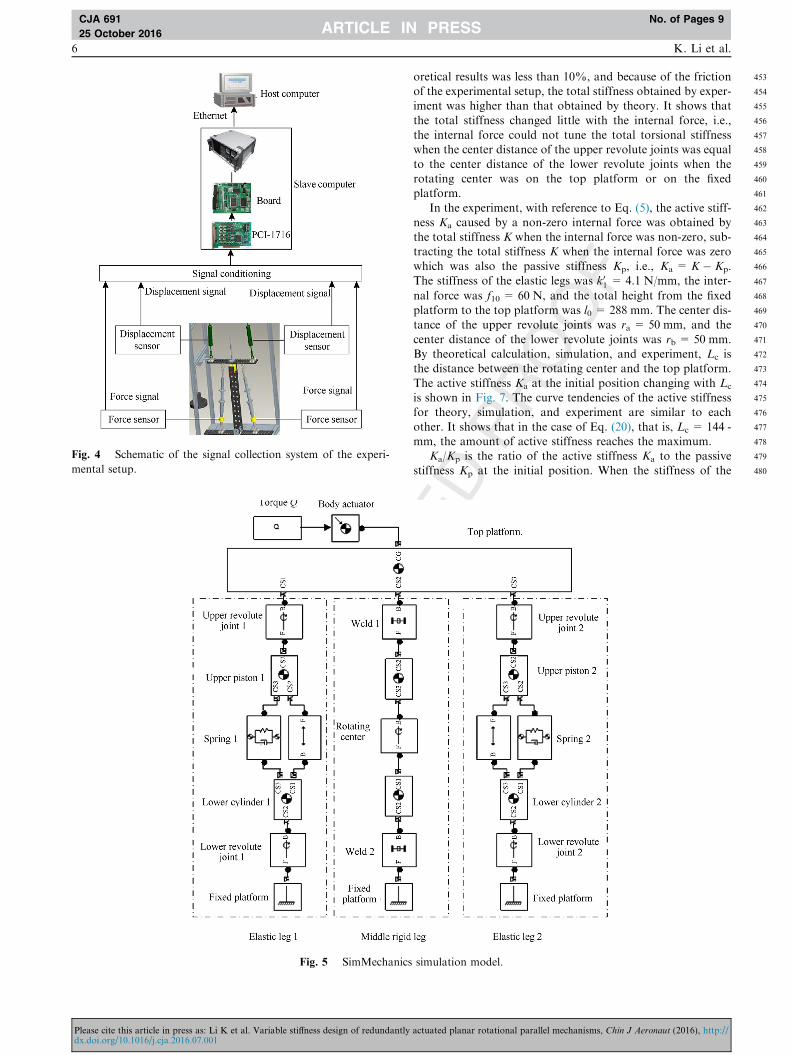
tion system of the experimental setup is shown in Fig. 4, inwhich the rotating angle was converted from the measurementsof the displacement sensors on both sides above the top plat-
form. The internal forces of the elastic legs were measuredby force sensors connected to the elastic legs on both sides.The experimental torsional stiffness was obtained by the ratio
of the load torque to the measured rotating angle. In addition,a SimMechanics simulation model of an RAPRPM corre-sponding to the experimental setup is shown in Fig. 5, which
consists of the top platform, elastic leg 1, elastic leg 2, andthe middle rigid leg. The torque was applied to the top plat-form to produce a rotating angle. Torsional stiffness in thesimulation was the ratio of the torque to the rotating angle.
The theoretical calculation was also verified by the MatlabSimMechanics simulation.
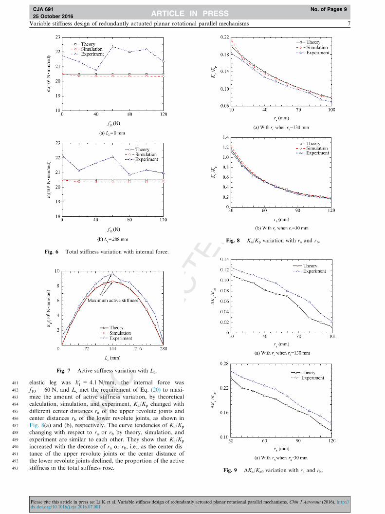
When the center distance of the upper revolute joints was
ra = 50 mm and the center distance of the lower revolute jointswas rb = 50 mm, ra = rb. The stiffness of the elastic legs wask01 = 4.1 N/mm, and the total height from the fixed platform
to the top platform was l0 = 288 mm. The distance betweenthe rotating center O and the top platform was Lc = 0 mm
or Lc = 288 mm. By theoretical calculation, simulation, andexperiment, the total stiffness K of Lc = 0 mm and Lc = 288 -mm at the initial position changing with the internal force of
the elastic leg f10 are shown in Fig. 6(a) and (b), respectively,and the result of simulation was very close to the theoreticalresult. In addition, the error between the experimental and the-
actuated planar rotational parallel mechanisms, Chin J Aeronaut (2016), http://
453
454
455
456
457
458
459
460
461
462
463
464
465
466
467
468
469
470
471
472
473
474
475
476
477
478
479
480
Fig. 4 Schematic of the signal collection system of the experi-
mental setup.
Fig. 5 SimMechanics
6 K. Li et al.
CJA 691 No. of Pages 9
25 October 2016
Please cite this article in press as: Li K et al. Variable stiffness design of redundantlydx.doi.org/10.1016/j.cja.2016.07.001
oretical results was less than 10%, and because of the frictionof the experimental setup, the total stiffness obtained by exper-iment was higher than that obtained by theory. It shows that
the total stiffness changed little with the internal force, i.e.,the internal force could not tune the total torsional stiffnesswhen the center distance of the upper revolute joints was equal
to the center distance of the lower revolute joints when therotating center was on the top platform or on the fixedplatform.
In the experiment, with reference to Eq. (5), the active stiff-ness Ka caused by a non-zero internal force was obtained bythe total stiffness K when the internal force was non-zero, sub-tracting the total stiffness K when the internal force was zero
which was also the passive stiffness Kp, i.e., Ka = K � Kp.The stiffness of the elastic legs was k01 = 4.1 N/mm, the inter-
nal force was f10 = 60 N, and the total height from the fixedplatform to the top platform was l0 = 288 mm. The center dis-tance of the upper revolute joints was ra = 50 mm, and the
center distance of the lower revolute joints was rb = 50 mm.By theoretical calculation, simulation, and experiment, Lc isthe distance between the rotating center and the top platform.
The active stiffness Ka at the initial position changing with Lc
is shown in Fig. 7. The curve tendencies of the active stiffnessfor theory, simulation, and experiment are similar to each
other. It shows that in the case of Eq. (20), that is, Lc = 144 -mm, the amount of active stiffness reaches the maximum.
Ka/Kp is the ratio of the active stiffness Ka to the passivestiffness Kp at the initial position. When the stiffness of the
simulation model.
actuated planar rotational parallel mechanisms, Chin J Aeronaut (2016), http://
481
482
483
484
485
486
487
488
489
490
491
492
493
Fig. 6 Total stiffness variation with internal force.
Fig. 7 Active stiffness variation with Lc.
Fig. 8 Ka/Kp variation with ra and rb.
Fig. 9 DKa/Ka0 variation with ra and rb.
Variable stiffness design of redundantly actuated planar rotational parallel mechanisms 7
CJA 691 No. of Pages 9
25 October 2016
elastic leg was k01 = 4.1 N/mm, the internal force was
f10 = 60 N, and Lc met the requirement of Eq. (20) to maxi-mize the amount of active stiffness variation, by theoreticalcalculation, simulation, and experiment, Ka/Kp changed with
different center distances ra of the upper revolute joints andcenter distances rb of the lower revolute joints, as shown inFig. 8(a) and (b), respectively. The curve tendencies of Ka/Kp
changing with respect to ra or rb by theory, simulation, and
experiment are similar to each other. They show that Ka/Kp
increased with the decrease of ra or rb, i.e., as the center dis-tance of the upper revolute joints or the center distance of
the lower revolute joints declined, the proportion of the activestiffness in the total stiffness rose.
Please cite this article in press as: Li K et al. Variable stiffness design of redundantly actuated planar rotational parallel mechanisms, Chin J Aeronaut (2016), http://dx.doi.org/10.1016/j.cja.2016.07.001
494
495
496
497
498
499
500
501
502
503
504
505
506
507
508
509
510
511
512
513
514515
516
517
518
519
520
521
522
523
524
525
526
527
528
529
530
531
532
533
534
535
536
537
538
539
540
541
542
543
544
545
546
547
548
549
550
551
552
553
554
555
556
557
558
559
560
561
562
563
564
565
566
567
568
569
570
571
572
573
574
575
576
577
578
579
580
581
582
583
584
585
586
587
588
589
590
591
592
593
594
595
596
597
598
599
600
601
602
603
604
605
606
607
608
609
610
611
612
613
614
8 K. Li et al.
CJA 691 No. of Pages 9
25 October 2016
DKa is the difference between the maximum active stiffnessKamax and the minimum active stiffness Kamin as the platformrotated from q = 0 to q= 0.1 rad. Ka0 is the active stiffness at
the initial position. The ratio DKa/Ka0 is the maximum changeof the active stiffness Ka during the rotation of the platform.When the stiffness of the elastic legs was k01 = 4.1 N/mm, the
internal force was f10 = 60 N, and Lc met the requirement ofEq. (20) to maximize the amount of active stiffness variation,
by theoretical calculation and experiment, for different centerdistances ra of the upper revolute joints and center distancesrb of the lower revolute joints, the ratio DKa/Ka0 changing with
ra and rb is shown in Fig. 9(a) and (b), respectively. The curvetendencies of DKa/Ka0 changing with ra and rb for the experi-ment are similar to the theoretical results. It shows that DKa/
Ka0 decreased with the increase of ra or rb, i.e., as the centerdistance of the upper revolute joints or the center distance ofthe lower revolute joints increased, the maximum change ofthe active stiffness Ka during the rotation of the platform
decreased.
4. Conclusions
(1) A novel design for stiffness variation was proposed tomaximize the change of stiffness with the internal forceand to minimize the dynamic change of stiffness with
the dynamic location of the mechanism by optimizingthe geometrical parameters of the mechanism. In addi-tion, the relationships between the stiffness and the geo-metrical parameters were established.
(2) Internal force cannot tune the total torsional stiffnesswhen the center distance of the upper revolute joints isequal to the center distance of the lower revolute joints,
when the rotating center is on the top platform or on thefixed platform. The necessary condition of internal forcetuning the stiffness is to avoid the situation.
(3) The positions of the rotating center maximizing theamount of stiffness variation with the internal force wereobtained. The proportion of active stiffness in total stiff-ness rises as the center distance of the upper revolute
joints or the center distance of the lower revolute jointsdeclines. The maximum change of active stiffness duringthe rotation of the platform decreases as the center dis-
tance of the upper revolute joints or the center distanceof the lower revolute joints increases. That is, the geo-metrical parameters maximize the change of stiffness
with the internal force and minimize the dynamic changeof total stiffness with the dynamic location of themechanism.
Acknowledgement
This study was supported by the National Natural ScienceFoundation of China (No. 51275127).
Appendix A. Supplementary material
Supplementary data associated with this article can be found,in the online version, at http://dx.doi.org/10.1016/j.cja.2016.
07.001.
Please cite this article in press as: Li K et al. Variable stiffness design of redundantlydx.doi.org/10.1016/j.cja.2016.07.001
References
1. Kucuk S. Simulation and design tool for performance analysis of
planar parallel manipulators. Simulat Trans Soc Model Simulat Int
2012;88(5):542–56.
2. Merlet JP. Direct kinematics of planar parallel manipulators. In:
Proceedings of IEEE conference 1996 on robotics and automation;
1996 April 22–28; Minneapolis, Minnesota; 1996. p. 3744–9.
3. Kucuk S. A dexterity comparison for 3-DOF planar parallel
manipulators with two kinematic chains using genetic algorithms.
Mechatronics 2009;19(6):868–77.
4. Merlet JP, Gosselin CM, Mouly N. Workspaces of planar parallel
manipulators. Mech Mach Theory 1998;33(1):7–20.
5. Klimchik A, Chablat D, Pashkevich A. Stiffness modeling for
perfect and non-perfect parallel manipulators under internal and
external loadings. Mech Mach Theory 2014;79:1–28.
6. Cui Z, Jiang HZ. A study of the planar serial-parallel mechanism
with various stiffness for a biotic compliant fish. In: Proceedings of
the ASME 2013 international mechanical engineering congress &
exposition; 2013 November 13–21; San Diego, California, USA;
2013. p. 1–6.
7. Epps BP, Alvarado PVY, Youcef-Toumi K, Techet AH. Swim-
ming performance of a biomimetic compliant fish-like robot. Exp
Fluids 2009;47(6):927–39.
8. Alvarado PV. Design of biomimetic compliant devices for
locomotion in liquid environments. J Dyn Syst Meas Contr
2007;128:3–13.
9. Alvarado PV. Design of biomimetic compliant devices for locomo-
tion in liquid environments [dissertation]. Massachusetts: Mas-
sachusetts Institute of Technology; 2007.
10. Tytell ED, Hsu CY, Williams TL, Cohen AH, Fauci LJ.
Interactions between internal forces, body stiffness, and fluid
environment in a neuromechanical model of lamprey swimming.
In: Proceedings of the 2010 national academy of sciences of the
United States of America; 2010. p. 19832–7.
11. Dasgupta BH, Mruthyunjaya TS. Force redundancy in parallel
manipulators: theoretical and practical issues. Mech Mach Theory
1998;33(6):727–42.
12. Chakarov D. Study of the antagonistic stiffness of parallel
manipulators with actuation redundancy. Mech Mach Theory
2004;39(6):583–601.
13. Mills JK. Hybrid actuator for robot manipulators: design, control
and performance. Mechatronics 1993;3(1):19–38.
14. Mittal S, Tasch U, Wang Y. A redundant actuation scheme for
independent modulations of stiffness and position of a robotic
joint. Mech Haptic Interf 1993;49:247–56.
15. Yokoi K, Kaneko M, Tanie K. Direct compliance control of
parallel link manipulators. In: Proceedings of the 8th CISM––
IFToMM symposium; Paris, France; 1990. p. 224–51.
16. Yokoi K, Kaneko M, Tanie K. Direct compliance control for a
parallel link arm. Trans Jpn Soc Mech Eng 1989;55(515):1690–6.
17. Gardner JF, Kumar V, Ho JH. Kinematics and control of
redundantly actuated closed chains. In: Proceedings of the 1989
IEEE international conference on robotics and automation; Scotts-
dale; 1989. p. 418–24.
18. Nahon MA, Angeles J. Force optimization in redundantly
actuated closed kinematic chains. In: Proceedings of the 1989
IEEE international conference on robotics and automation; Scotts-
dale; 1989. p. 951–6.
19. Tadokoro S. Control of parallel mechanisms. Adv Robot 1993;8
(6):559–71.
20. Cho W, Tesar D, Freeman RA. The dynamic and stiffness
modeling of general robotic manipulator systems with antagonistic
actuation. In: Proceedings of the 1989 IEEE international confer-
ence on robotics and automation; 1989. p. 1380–7.
21. Yi BJ, Freeman RA. Geometric characteristics of antagonistic
stiffness in redundantly actuated mechanisms. In: Proceedings of
actuated planar rotational parallel mechanisms, Chin J Aeronaut (2016), http://
615
616
617
618
619
620
621
622
623
624
625
626
627
628
629
630
631
632
633
634
635
636
637
638
639
640
641
642
643
644
645
646
647
648
649
650
651
652
653
654
655
656
657
658
659
660
661
662
663
664
665666
667
668
669
670
671
672
673674
675
676
677678
679
680
681
682683
Variable stiffness design of redundantly actuated planar rotational parallel mechanisms 9
CJA 691 No. of Pages 9
25 October 2016
the 1989 IEEE international conference on robotics and automation;
1993. p. 654–61.
22. Yi BJ, Oh SR. Analysis of a 5-bar finger mechanism having
redundant actuators with applications to stiffness. In: Proceedings
of the 1989 IEEE international conference on robotics and automa-
tion; Albuquerque; 1997. p. 759–65.
23. Yi BJ, Freeman RA, Tesar D. Open-loop stiffness control of
overconstrained mechanisms/robotic linkage systems. In: Proceed-
ings of the 1989 IEEE international conference on robotics and
automation; 1989. p. 1340–5.
24. Adli M, Ito K, Hanafusa H. A method for modulating the contact
compliance in objects held by dual-arm robots. In: Proceedings of
the 1995 IEEE international conference on recent advances in
mechatronics; Istanbul, Turkey; 1995. p. 1065–72.
25. Sungcheul L, Sitae K, Woosung I, Moonki K, Jay IJ, Jongwon K.
Experimental verification of antagonistic stiffness planning for a
planar parallel mechanism with 2-DOF force redundancy. Robot-
ica 2011;29(7):547–54.
26. Kucuk S. Energy minimization for 3-RRR fully planar parallel
manipulator using particle swarm optimization. Mech Mach
Theory 2013;62(4):129–49.
27. Toz M, Kucuk S. Dimensional optimization of 6-DOF 3-CCC
type asymmetric parallel manipulator. Adv Robot 2014;28
(9):625–37.
28. Marc A, Roger B. The synthesis of three-degree-of-freedom planar
mechanisms with revolute joints (3-RRR) for an optimal singu-
larity-free workspace. J Robot Syst 2004;21(5):259–74.
29. Chi Z, Zhang D, Xia L, Zhen G. Multi-objective optimization of
stiffness and workspace for a parallel kinematic machine. Int J
Mech Mater Des 2012;9(3):281–93.
30. Arsenault M, Boudreau R, Arsenault M. Synthesis of planar
parallel mechanisms while considering workspace, dexterity,
stiffness and singularity avoidance. J Mech Des 2006;128
(12):69–78.
Please cite this article in press as: Li K et al. Variable stiffness design of redundantlydx.doi.org/10.1016/j.cja.2016.07.001
31. Shin H, Lee S, Jeong JI, Jongwon K. Antagonistic stiffness
optimization of redundantly actuated parallel manipulators in a
predefined workspace. In: Proceedings of the 1995 IEEE/ASME
international conference on transactions on mechatronics; 2013. p.
1161–9.
32. Dai XL, Huang QT, Jiang HZ, Han JW. Kinematics analysis of a
3-dof rotational parallel mechanism. In: 2008 international work-
shop on modelling, simulation and optimization; 2008. p. 404–7.
33. Tian TZ, Jiang HZ, Tong ZZ, He JF, Huang QT. An inertial
parameter identification method of eliminating system damping
effect for a six-degree-of-freedom parallel manipulator. Chin J
Aeronaut 2015;12(2):582–92.
Li Kangkang is a Ph. D. candidate in the School of Mechatronics
Engineering at Harbin Institute of Technology. His area of research
includes variable stiffness design of serial-parallel redundantly actu-
ated mechanisms and robotic fish.
Jiang Hongzhou received his B.S. degree from Dalian Jiaotong
University in 1993 and his M.S. and Ph.D. degrees from Harbin
Institute of Technology, China in 1996 and 2000, respectively. He is
currently a professor in the School of Mechatronic Engineering at
Harbin Institute of Technology. His research interests include parallel
manipulators, biomimetic robotics, system simulation, and control
system development.
Cui Zuo is a Ph. D. candidate in the School of Mechatronics Engi-
neering at Harbin Institute of Technology. His area of research
includes biomimetic robotics.
Huang Qun is a M.S. student in the School of Mechatronics Engi-
neering at Harbin Institute of Technology, where he received his B.S.
degree in 2015. His area of research includes dynamics of serial-parallel
redundantly actuated mechanisms.
actuated planar rotational parallel mechanisms, Chin J Aeronaut (2016), http://
![CHAPTER 4: ACTUATED CONTROLLER TIMING PROCESSES … · Chapter 4: Actuated Controller Timing Processes 89 [2012.12.19] CHAPTER 4: ACTUATED CONTROLLER TIMING PROCESSES This chapter](https://static.fdocuments.in/doc/165x107/5f68dd109d404110520123b9/chapter-4-actuated-controller-timing-processes-chapter-4-actuated-controller-timing.jpg)