
VARIABLE SPEED DRIVE NANO - motive · interface program “Motive ... industrial environment, but...
12
VARIABLE SPEED DRIVE NANO
Transcript of VARIABLE SPEED DRIVE NANO - motive · interface program “Motive ... industrial environment, but...

VARIABLE SPEED DRIVE NANO

NEO-WIFI tutorial
https://www.youtube.com/watch?v=hUXJ47P_Qxo&feature=youtu.be
NEO-PUMP
NEO-COMP
https://www.youtube.com/watch?v=7y1J4rFUVy8
https://www.youtube.com/watch?v=y8yHVdYIRKA
NEO-VENT https://www.youtube.com/watch?v=dBcVtzZGyAM&feature=youtu.be
the brothers:
INDEX
Description pag. 2-3
Main data pag. 4Main functions pag. 5
Electrical assembly pag. 6-7
Declaration of conformy pag. 8
Technical manual

DESCRIPTION
Setting and command can also be made by a PC, thanks to the free PC interface program “Motive Motor Manager”
NANO can be commanded by analog controls
or MODBUS.
Any NANO can be fi xed to a wide range of motors of different power and size.
Thanks to BLUE, motive bluetooth trasnsmitter for NANO and NEO, and to the free App NANO, you can make the setting or command NANO
via tablets or
smartphones.
NANO is for single phase supply, three phase motors. This permits NANO to add to the well known power saving of variable speed drives, the possibility to replace the single phase motors (technically losing lot of power) with the higher effi centy IE2 and IE3 three phase motors.
2
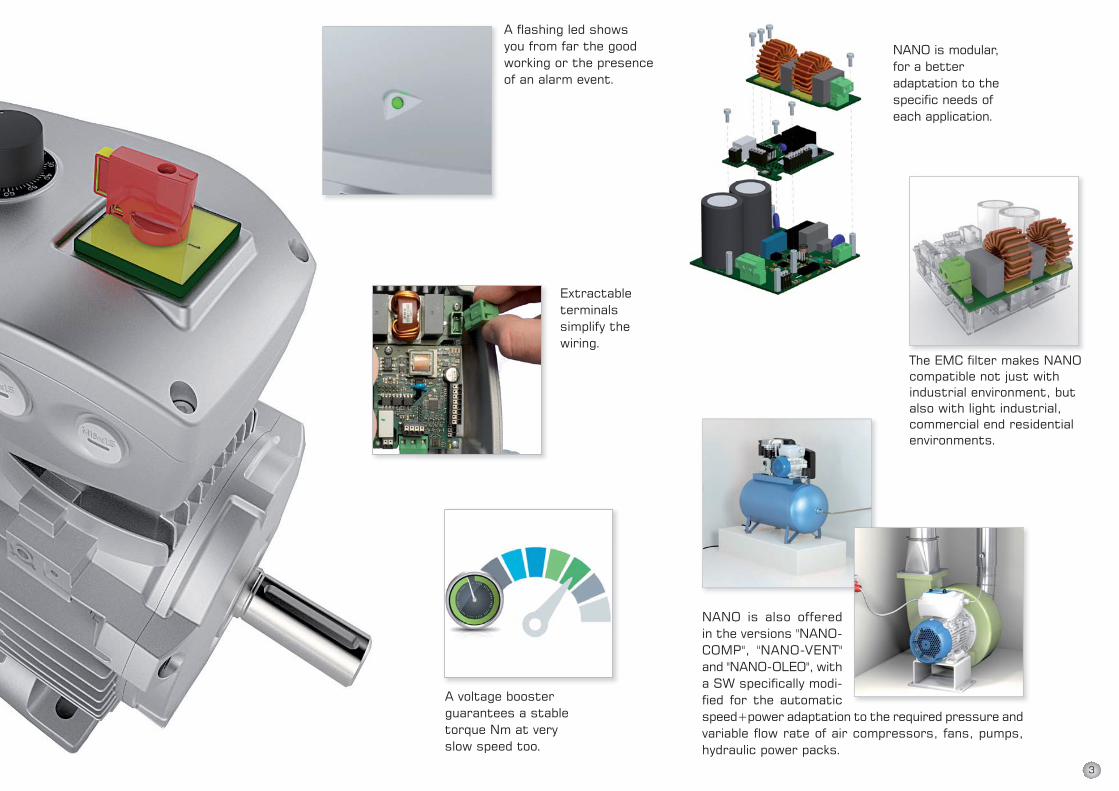
Extractable terminals simplify the wiring.
A fl ashing led shows you from far the good working or the presence of an alarm event.
NANO is also offered in the versions "NANO-COMP", "NANO-VENT" and "NANO-OLEO", with a SW specifi cally modi-fi ed for the automatic speed+power adaptation to the required pressure and variable fl ow rate of air compressors, fans, pumps, hydraulic power packs.
The EMC fi lter makes NANO compatible not just with industrial environment, but also with light industrial, commercial end residential environments.
A voltage booster guarantees a stable torque Nm at veryslow speed too.
NANO is modular, for a better adaptation to the specifi c needs of each application.
3

0.13 0.18 0.25 0.37 0.55 0.55 0.75 1.1 1.5 1.9 2..2
NANO-0.75
NANO-2.2
63 71 80 90S 90L 100L 112M 132S
NANO-0.75
NANO-2.2
MAIN DATA
*IP65 degree refers to the inverter case and to the optional components on the cover (Power Switch and Potentiometer).
Physical dimension Symbol U.O.M NANO-0.75 NANO-2.2
Inverter protection degree* IP IP65*
Inverter input voltage V1n V 1x110(-10%)÷240(+10%)
Inverter input frequency f1n Hz 50/60 (±5%)
Maximum output voltage of NANO V2 V 0,95 • V1n
Inverter output frequency f2 Hz 200% f1n(f2 0÷100Hz withf1n50Hz)
Rated input inverter current I1n A 5 10
Rated output inverter current (to the motor) I2n A 4 9
Maximum output current of NANO I2 A I2n + 5%
150%
200% I2
-20 … +70
0 … +40
5 … 85 without condensation
Maximum Starting torque / Rated torque ratio Cs/Cn Nm
Maximum Starting current (kept for 3 seconds) I2max A
Storage temperature Tstock °C
Environment al operating temperature Tamb °C
Maximum relative humidity % (40°C)
Other characteristics NANO-0.75 NANO-2.2
Motor control V / F
EMC for DOMESTIC, COMMERCIAL AND LIGHT INDUSTRIAL ENVIRONMENT With optional code NANFILTor with external EMC fi lterEMC for INDUSTRIAL ENVIRONMENT
Analog/Digital I/O Module Optional, code NANEXPS
Power Switch IP65 Optional, code INTEM1X12A
Potentiometer with Knob and Unit Scale IP65 Optional, code NANPOT
Bluetooth module for smartphone and tablet control Optional, code BLUE
Communication Protocol MODBUS RS485
Table RP: Power range of motors that can be connected (at 230Vac)
Table RD: Size range of IEC motors that can be connected
KW motor
IEC Motor
4
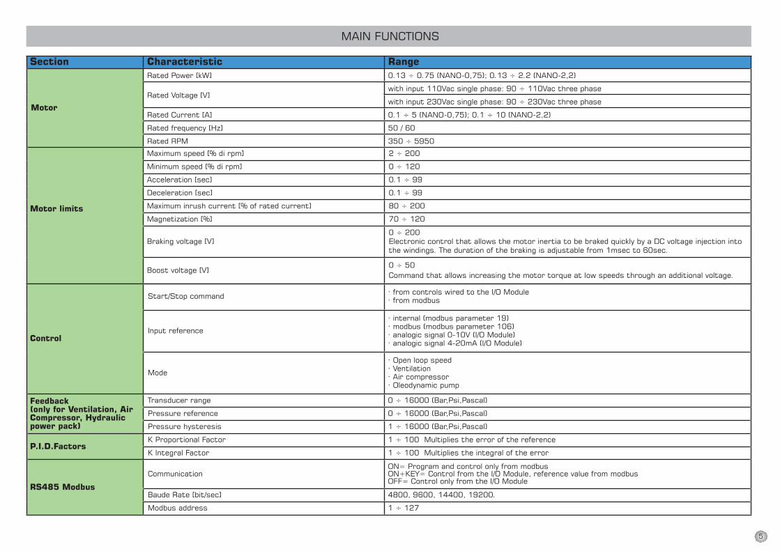
MAIN FUNCTIONS
Section Characteristic RangeRated Power [kW] 0.13 ÷ 0.75 (NANO-0,75); 0.13 ÷ 2.2 (NANO-2,2)
Rated Voltage [V]with input 110Vac single phase: 90 ÷ 110Vac three phase
with input 230Vac single phase: 90 ÷ 230Vac three phase
Rated Current [A] 0.1 ÷ 5 (NANO-0,75); 0.1 ÷ 10 (NANO-2,2)
Rated frequency [Hz] 50 / 60
Rated RPM 350 ÷ 5950
Motor limits
Maximum speed [% di rpm] 2 ÷ 200
Minimum speed [% di rpm] 0 ÷ 120
Acceleration [sec] 0.1 ÷ 99
Deceleration [sec] 0.1 ÷ 99
Maximum inrush current [% of rated current] 80 ÷ 200
Magnetization [%] 70 ÷ 120
Braking voltage [V]0 ÷ 200Electronic control that allows the motor inertia to be braked quickly by a DC voltage injection into the windings. The duration of the braking is adjustable from 1msec to 60sec.
Boost voltage [V]0 ÷ 50 Command that allows increasing the motor torque at low speeds through an additional voltage.
Control
Start/Stop command · from controls wired to the I/O Module· from modbus
Input reference
· internal (modbus parameter 19)· modbus (modbus parameter 106)· analogic signal 0-10V (I/O Module)· analogic signal 4-20mA (I/O Module)
Mode
· Open loop speed· Ventilation· Air compressor· Oleodynamic pump
Feedback(only for Ventilation, Air Compressor, Hydraulic power pack)
Transducer range 0 ÷ 16000 (Bar,Psi,Pascal)
Pressure reference 0 ÷ 16000 (Bar,Psi,Pascal)
Pressure hysteresis 1 ÷ 16000 (Bar,Psi,Pascal)
P.I.D.FactorsK Proportional Factor 1 ÷ 100 Multiplies the error of the reference
K Integral Factor 1 ÷ 100 Multiplies the integral of the error
RS485 Modbus
CommunicationON= Program and control only from modbusON+KEY= Control from the I/O Module, reference value from modbusOFF= Control only from the I/O Module
Baude Rate [bit/sec] 4800, 9600, 14400, 19200.
Modbus address 1 ÷ 127
Motor
5

ELECTRICAL ASSEMBLY
Terminal Function
L Supply inverter phase.
N Supply inverter neutral phase.
U U phase motor connection.
V V phase motor connection.
W W phase motor connection.
A+ High signal ModBus RS485.
B- Low signal ModBus RS485.
sh Ground for Modbus RS485 cable shield.
0V 0Vdc supply.
12Vdc 12Vdc supply for all the electronic Inputs (analogic e digital) and DO1 Digital Output.
FAN+
FAN -
AI0
Analog Input 0, programmable in the following functions:• speed reference with potentiometer;• speed reference with external signal;• current limit reference;• PID feedback (for example: connection of a transducer).The type of input signal can be in voltage (0-10V) or in current (4-20mA).
AI1
Analog Input 1, programmable in the following functions:• speed reference with potentiometer;• speed reference with external signal;• current limit reference;• PID feedback (for example: connection of a transducer).The type of input signal can be in voltage (0-10V) or in current (4-20mA).
AO0Analog Output 0, programmable in the following functions:• 0-12V motor speed reference (from 0% to the maximum speed value set);• 0-12V motor current absorbed reference (from 0% to the maximum absorption set).
0V 0Vdc supply for AO0 Analogic Output.
DI0
Digital Input 0, programmable in the following functions:• Start/Stop motor command clockwise direction (1=Start, 0=Stop);• Start/Brake motor command (1=Start, 0=Brake);• reverse motor command (it works only when Start/Stop motor command is set to a Digital Input with value=1) • brake motor command (can also be used as an inverter enable or as an emergency stop);• Start/Stop motor command counter-clockwise direction (1=Start, 0=Stop).
DI1
Digital Input 1, programmable in the following functions:• Start/Stop motor command clockwise direction (1=Start, 0=Stop);• Start/Brake motor command (1=Start, 0=Brake);• reverse motor command (it works only when Start/Stop motor command is set to a Digital Input with value=1) • brake motor command (can also be used as an inverter enable or as an emergency stop);• Start/Stop motor command counter-clockwise direction (1=Start, 0=Stop).
DI2
Digital Input 2, programmable in the following functions:• Start/Stop motor command clockwise direction (1=Start, 0=Stop);• Start/Brake motor command (1=Start, 0=Brake);• reverse motor command (it works only when Start/Stop motor command is set to a Digital Input with value=1) • brake motor command (can also be used as an inverter enable or as an emergency stop);• Start/Stop motor command counter-clockwise direction (1=Start, 0=Stop).
DO0
Digital Output 0 N.O. contact, programmable in the following functions:• signaling when the motor is running;• signaling of the motor rotation sense (0=clockwise, 1=counter-clockwise);• signaling maximum speed reached;• motoinverter fault;• signaling when the motor is stopped;• load/unload electric valve control (air compressor mode).
DO1
Digital Output 1, programmable in the following functions:• signaling when the motor is running;• signaling of the motor rotation sense (0=clockwise, 1=counter-clockwise);• signaling maximum speed reached;• motoinverter fault;• signaling when the motor is stopped;• load/unload electric valve control (air compressor mode).When is enabled, DO1 Digital Output supplies 0Vdc signal: this signal can be used to drive a relay (use the 12Vdc supplied by the inverter).
NANO-0.75 and NANO-2.2 Analog/Digital I/O Module (optional code NANEXPS)
12Vdc supply (max 1A) for inverter ventilation. It’s automatically enabled when the IGBT module starts to overheat.
6

ELECTRICAL ASSEMBLY
Power Module layout NANO-0.75
Analog/Digital I/OModule layout (optional, code NANEXPS)
EMC fi lter layout (optional, code NANFILT)
Bluetooth module for smartphone and tablet control
(optional, code BLUE)
Power Module layout NANO-2.2
7
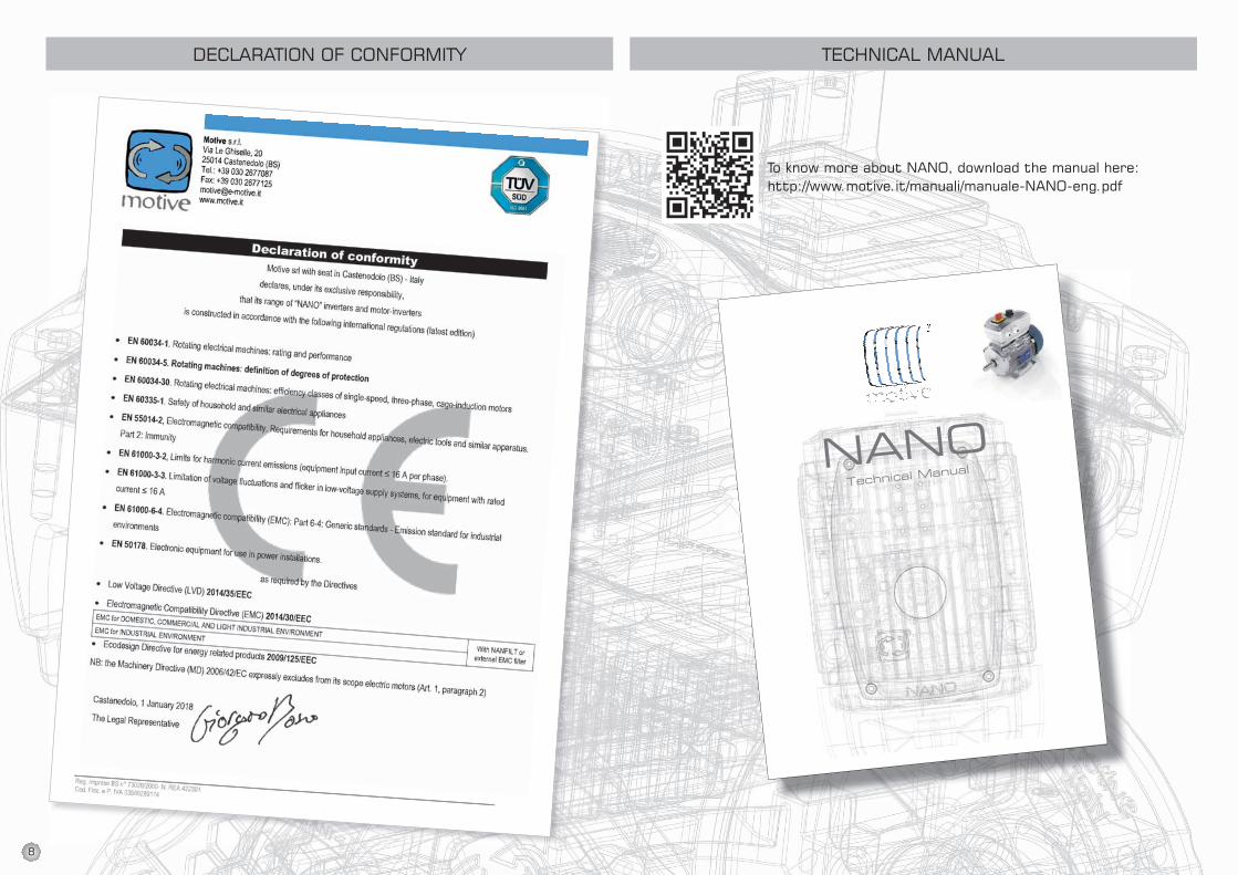
DECLARATION OF CONFORMITY TECHNICAL MANUAL
To know more about NANO, download the manual here:http://www.motive.it/manuali/manuale-NANO-eng.pdf
8

ARTICLE 1GUARANTEE
1.1 Barring written agreements, entered into between the parties hereto each time, Motive hereby guarantees compliance with spe-cific agreements.The guarantee for defects shall be restricted to product defects following design, materials or ma-nufacturing defects leading back to Motive.The guarantee shall not include: * Faults or damages ensuing from
transport. Faults or damages ensuing from installation de-fects; incompetent use of the product, or any other unsuitable use.
* Tampering or damages ensuing from use by non-authorised staff and/or use of non-original parts and/or spare parts;
* Defects and/or damages ensuing from chemical agents and/or atmospheric phenomena (e.g. burnt out material, etc.); rou-tine maintenance and required action or checks;
* Products lacking a plate or ha-ving a tempered plate.
1.2 Returns to credit or replace will be accepted only in exceptional cases; however returns of goods already used to credit or replace won’t be accepted in any case.The guarantee shall be effective for all Motive products, with a term of validity of 12 months, starting from the date of shipment.The guarantee shall be subject to specific written request for Motive to take action, according to statements, as described at
the paragraphs herein below. By virtue of aforesaid approval, and as regards the claim, Motive shall be bound at its discretion, and within a reasonable time-limit, to alter-natively take the following actions:a) To supply the Buyer with products of the same type and quality as those having proven defective and not complying with agreements, free ex-works; in aforesaid case, Motive shall have the right to request, at Buyer’s charge, early return of defective goods, which shall become Moti-ve’s property;b) To repair, at its charge , the defective product or to modify the product which does not comply with agreements, by performing aforesaid action at its facilities; in aforesaid cases, all costs re-garding product transport shall be sustained by the Buyer.c) To send spare parts free of charge: all costs regarding pro-duct transport shall be sustained by the Buyer.
1.3. The guarantee herein shall as-similate and replace legal guaran-tees for defects and discrepan-cies, and shall exclude any other eventual Motive liability, however caused by supplied products; in particular, the Buyer shall have no right to submit any further claims.Motive shall not be liable for the enforcement of any further claims, as of the date the guarantee’s term of validity expires.
ALL DATA HAVE BEEN WRITTEN AND CHECKED WITH THE
GREATEST CARE.WE DO NOT TAKE ANY RESPONSI-BILITY FOR POSSIBLE ERRORS OR
OMISSIONS.MOTIVE CAN CHANGE THE
CHARACTERISTIC OF THE SOLD ITEMS ON HIS FIRM OPINION AND
IN EVERY MOMENT.
ARTICLE 2CLAIMS
2.1. Claims, regarding quantity, weight, gross weight and colour, or claims regarding faults and defects in quality or compliance, and which the Buyer may discover on goods delivery, shall be submit-ted by a max.7 days of aforesaid discovery, under penalty of nullity.
ARTICLE 3DELIVERY
3.1. Any liability for damages en-suing from total or partial delayed or failed delivery, shall be excluded.
3.2. Unless differently commu-nicated by written to the Client, the transport terms have to be intended ex-works.
ARTICLE 4PAYMENT
4.1. Any delayed or irregular payments shall entitle Motive to cancel ongoing agreement, inclu-ding agreements which do not regard the payments at issue, as well as entitling Motive to claim damages, if any. Motive shall, however, have the right, as of payment’s due date and without placing in arrears, to claim inte-rest for arrears, to the extent of the discount rate in force in Italy, increased by 12 points. Motive shall also have the right to withhold material under repair for replacement. In the case of failed payment, Motive shall have the right to cancel all guarantees of materials, as regards the insol-vent Client.
4.2. The Buyer shall be bound to complete payment, including ca-ses whereby claims or disputes are underway.
TERMS OF SALE AND GUARANTEE
NEO-VENTVFD control unit for air suction and ventilation
NEO-COMPcompressors
control unit
Motive s.r.l.
Via Le Ghiselle, 20
25014 Castenedolo (BS) - Italy
Tel.: +39.030.2677087 - Fax: +39.030.2677125
web site: www.motive.it
e-mail: [email protected]
LOO
KS
GOOD, PERFORMS BETTE
R
NA
NO
CAT
ALO
GU
E E
NG
FEB
18
R
EV.
00
AREA DISTRIBUTOR
WATCH OUR FURTHER CATALOGUES: